Abstract
An ultrasonic horn includes: a vertical vibration generating portion in which a first ultrasonic vibrator is mounted inside; a horn portion extending forward from the vertical vibration generating portion, amplifying an ultrasonic vibration generated by the vertical vibration generating portion, and to which a capillary is mounted at a front end portion; and a torsional vibration generating portion extending rearward from the vertical vibration generating portion. The torsional vibration generating portion includes: a rod-shaped body; vibration members arranged axisymmetrically around a central axis; second ultrasonic vibrators sandwiched between the rod-shaped body and the vibration members such that a vibration direction is a circumferential direction; and bolts pressurizing the second ultrasonic vibrators.
Claims (7)
1 . An ultrasonic horn, which is an ultrasonic horn used in a wire bonding apparatus, comprising: a vertical vibration generating portion in which a first ultrasonic vibrator is mounted inside such that a vibration direction is a front-rear direction; a horn portion extending forward from the vertical vibration generating portion, amplifying an ultrasonic vibration generated by the vertical vibration generating portion, and to which a bonding tool is mounted at a front end portion; and a torsional vibration generating portion extending rearward from the vertical vibration generating portion, wherein the torsional vibration generating portion comprises: a rod-shaped body extending rearward from the vertical vibration generating portion; a pair of vibration members arranged axisymmetrically around a longitudinal central axis of the rod-shaped body and having a mass smaller than the rod-shaped body; a pair of second ultrasonic vibrators axisymmetric around the longitudinal central axis of the rod-shaped body and sandwiched between the rod-shaped body and each of the vibration members such that a vibration direction is a circumferential direction; and a pair of pressurizing mechanisms respectively compressing each of the second ultrasonic vibrators sandwiched between the rod-shaped body and each of the vibration members and pressurizing each of the second ultrasonic vibrators.
Show 6 dependent claims
2 . The ultrasonic horn according to claim 1 , wherein the rod-shaped body has a pair of notch portions formed axisymmetrically around the longitudinal central axis, each of the vibration members is a separate member from the rod-shaped body and is fitted into each of the notch portions, and the pressurizing mechanism is a bolt screwed into the rod-shaped body or the vibration member and compressing the second ultrasonic vibrator sandwiched between the rod-shaped body and the vibration member.
3 . The ultrasonic horn according to claim 2 , wherein the second ultrasonic vibrator is configured by stacking a plurality of piezoelectric elements that vibrate in a thickness direction when a high-frequency power is applied.
4 . The ultrasonic horn according to claim 1 , wherein each of the vibration members is a portion partitioned by slits provided axisymmetrically around the longitudinal central axis of the rod-shaped body and extending radially, and a part thereof is respectively connected to the rod-shaped body; the pair of second ultrasonic vibrators are respectively arranged in each recess portion between the rod-shaped body and each of the vibration members; and the pressurizing mechanism is a wedge inserted between the second ultrasonic vibrator in the recess portion and the rod-shaped body or between the second ultrasonic vibrator and the vibration member.
5 . The ultrasonic horn according to claim 4 , wherein the second ultrasonic vibrator is configured by stacking a plurality of piezoelectric elements that vibrate in a thickness direction when a high-frequency power is applied.
6 . The ultrasonic horn according to claim 4 , wherein the rod-shaped body comprises: a pair of horizontal slits formed from a rear end surface to a longitudinal center and extending radially outward horizontally from a central portion; a pair of vertical slits formed from the rear end surface to the longitudinal center and extending radially outward, upward and downward from the central portion; and a pair of fan-shaped slits extending diagonally upward and diagonally downward from the central portion at the longitudinal center, wherein the pair of horizontal slits, the pair of vertical slits, and the pair of fan-shaped slits are provided axially axisymmetrically around the longitudinal central axis of the rod-shaped body, one vibration member is a portion partitioned by one horizontal slit, one vertical slit, and one fan-shaped slit and the other vibration member is a portion partitioned by the other horizontal slit, the other vertical slit, and the other fan-shaped slit; and the one vibration member and the other vibration member are each connected to the rod-shaped body at the central portion.
7 . The ultrasonic horn according to claim 1 , wherein the second ultrasonic vibrator is configured by stacking a plurality of piezoelectric elements that vibrate in a thickness direction when a high-frequency power is applied.
Full Description
Show full text →
CROSS-REFERENCE TO RELATED APPLICATION
This application is a 371 application of the International PCT application serial no. PCT/JP2021/004918, filed on Feb. 10, 2021. The entirety of the above-mentioned patent application is hereby incorporated by reference herein and made a part of this specification.
TECHNICAL FIELD
The present invention relates to an ultrasonic horn that ultrasonically vibrates a bonding tool mounted to a tip. RELATED ART A wire bonding apparatus is often used to connect an electrode of a semiconductor die and a lead of a lead frame using a wire. After bonding the wire and the electrode by ultrasonically vibrating a capillary with the wire pressed onto the electrode by the capillary, the wire bonding apparatus stretches the wire to the lead, and with the stretched wire pressed onto the lead, and applies ultrasonic vibrations to the capillary to bond the wire and the lead. On the other hand, in order to improve the bonding quality and the bonding strength, a method of vibrating the tip of the bonding tool in multiple directions has been proposed. For example, Patent Literature 1 proposes a method in which an ultrasonic vibrator, stacked with piezoelectric elements in which two regions separated by a notch portion in a direction parallel to an electrode surface are formed, is mounted to an ultrasonic horn, and electric power of different frequencies is supplied to each region of the piezoelectric elements to vibrate the tip of a bonding tool mounted to the ultrasonic horn in multiple direction so as to generate a scrubbing motion. CITATION LIST Patent Literature [Patent Literature 1] Japanese Patent No. 6180736
SUMMARY
OF INVENTION Technical Problem However, since the method described in Patent Literature 1 uses a special ultrasonic vibrator, there has been a problem that the structure and driving device of the ultrasonic vibrator become complicated. Therefore, the present invention provides an ultrasonic horn that vibrates the bonding tool mounted to the tip in multiple directions with a simple structure. Solution to Problem The ultrasonic horn of the present invention includes a vertical vibration generating portion in which a first ultrasonic vibrator is mounted inside such that a vibration direction is a front-rear direction; a horn portion extending forward from the vertical vibration generating portion, amplifying an ultrasonic vibration generated by the vertical vibration generating portion, and to which a bonding tool is mounted at a front end portion; and a torsional vibration generating portion extending rearward from the vertical vibration generating portion. The torsional vibration generating portion includes a rod-shaped body extending rearward from the vertical vibration generating portion; a pair of vibration members arranged axisymmetrically around a longitudinal central axis of the rod-shaped body and having a mass smaller than the rod-shaped body; a pair of second ultrasonic vibrators axisymmetric around the longitudinal central axis of the rod-shaped body and sandwiched between the rod-shaped body and each of the vibration members such that a vibration direction is a circumferential direction; and a pair of pressurizing mechanisms compressing each of the second ultrasonic vibrators sandwiched between the rod-shaped body and each of the vibration members and pressurizing each of the second ultrasonic vibrators. As a result, by ultrasonically vibrating the first ultrasonic vibrator the tip of the bonding tool in the front-rear direction of the ultrasonic horn by the first ultrasonic vibrator by generating torsional vibration in the torsional vibration generating portion by the second ultrasonic vibrator generates, the tip of the bonding tool may be ultrasonically vibrated in a lateral direction orthogonal to the front-rear direction. In the ultrasonic horn of the present invention, the rod-shaped body has a pair of notch portions formed axisymmetrically around the longitudinal central axis, each of the vibration members is a separate member from the rod-shaped body and is fitted into each of the notch portions, and the pressurizing mechanism may be a bolt screwed into the rod-shaped body or the vibration member and compressing the second ultrasonic vibrator sandwiched between the rod-shaped body and the vibration member. Since the vibration member is a separate member from the rod-shaped body, and the second ultrasonic vibrator is sandwiched between them and fastened with a bolt, the overall configuration can be simplified. In the ultrasonic horn of the present invention, each of the vibration members is a portion partitioned by slits provided axisymmetrically around the longitudinal central axis of the rod-shaped body and extending radially, and a part thereof is respectively connected to the rod-shaped body; the pair of second ultrasonic vibrators are respectively arranged in each recess portion between the rod-shaped body and each of the vibration members; and the pressurizing mechanism is a wedge inserted between the second ultrasonic vibrator in the recess portion and the rod-shaped body or between the second ultrasonic vibrator and the vibration member. Since the vibration member is partitioned by the slits, the number of parts can be reduced and the structure can be simplified. In the ultrasonic horn of the present invention, the second ultrasonic vibrator may be configured by stacking a plurality of piezoelectric elements that vibrate in a thickness direction when a high frequency power is applied. As a result, the tip of the bonding tool may be ultrasonically vibrated in the lateral direction without using a special piezoelectric element. Effects of Invention The present invention is capable of providing an ultrasonic horn that vibrates a bonding tool mounted to the tip in multiple direction with a simple structure.
BRIEF DESCRIPTION OF DRAWINGS
is a plan view of an ultrasonic horn according to an embodiment. is an elevation view showing a front end portion of an ultrasonic horn according to an embodiment. is an axial cross-sectional view of a torsional vibration generating portion of an ultrasonic horn according to an embodiment, and is cross section A-A shown in . is a longitudinal cross-sectional view of a torsional vibration generating portion of an ultrasonic horn according to an embodiment, and is a B-B cross section shown in . is a longitudinal cross-sectional view of a torsional vibration generating portion of an ultrasonic horn according to an embodiment, and is a C-C cross section shown in . is a plan view of an ultrasonic horn according to another embodiment. is an axial cross-sectional view of a torsional vibration generating portion of an ultrasonic horn according to another embodiment, and is a D-D cross section shown in . is a longitudinal cross-sectional view of a torsional vibration generating portion of an ultrasonic horn according to another embodiment, and is E-E cross section shown in . is a longitudinal cross-sectional view of a torsional vibration generating portion of an ultrasonic horn according to another embodiment, and is F-F cross section shown in .
DESCRIPTION OF EMBODIMENTS
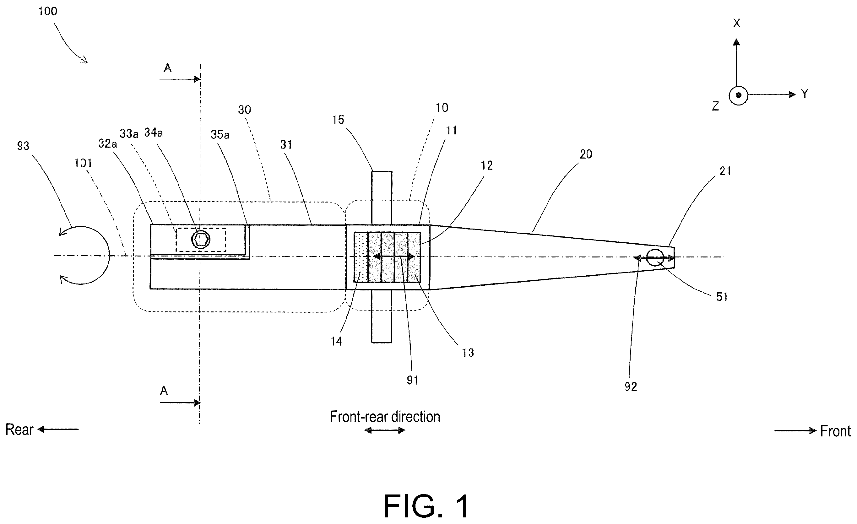
Hereinafter, an ultrasonic horn 100 of the embodiment will be described with reference to the drawings. As shown in , the ultrasonic horn 100 includes a vertical vibration generating portion 10 , a horn portion 20 , and a torsional vibration generating portion 30 . In the following description, the extending direction of a longitudinal central axis 101 of the ultrasonic horn 100 is taken as a Y direction or the front-rear direction, the direction perpendicular to the Y direction in the horizontal plane is taken as an X direction or a lateral direction, and the up-and-down direction is taken as a Z direction. Further, the side of the horn portion 20 will be described as the front or the positive side in the Y direction, and the side of the torsional vibration generating portion 30 will be described as the rear or the negative side in the Y direction. The central axis 101 is a virtual axis. The vertical vibration generating portion 10 is includes a casing 11 , a first ultrasonic vibrator 13 , and a wedge 14 . The casing 11 is made of metal such as titanium and has an opening 12 in a center for accommodating the first ultrasonic vibrator 13 . Further, on an outer surface of the casing 11 , a mounting arm 15 extending respectively in the positive side in the X direction and the negative side in the X direction is provided. The first ultrasonic vibrator 13 is configured by stacking a plurality of piezoelectric elements such as a piezoelectric element that vibrates in the thickness direction when a voltage is applied. The first ultrasonic vibrator 13 is mounted in the opening 12 of the casing 11 such that the stacking direction, which is the vibration direction, is the front-rear direction. Then, the wedge 14 is inserted between a rear end surface of the opening 12 and a rear end surface of the first ultrasonic vibrator 13 . The wedge 14 compresses the first ultrasonic vibrator 13 in the front-rear direction and applies a pressurization in the front-rear direction to the first ultrasonic vibrator 13 . The horn portion 20 is a portion that extends forward from the casing 11 of the vertical vibration generating portion 10 and amplifies the ultrasonic vibration in the front-rear direction generated by the vertical vibration generating portion 10 . The horn portion 20 is made of metal integrally formed with the casing 11 of the vertical vibration generating portion 10 , and its width or diameter decreases from a root portion connected to the front end of the casing 11 toward a front end portion 21 . As shown in , a capillary 51 , which is a bonding tool, is mounted to the front end portion 21 of the horn portion 20 . As shown in and , the torsional vibration generating portion 30 includes a rod-shaped body 31 , a pair of vibration members 32 a and 32 b , a pair of second ultrasonic vibrators 33 a and 33 b , and a pair of bolts 34 a and 34 b as a pair of pressurizing mechanisms. In , an alternate long and short dash line 102 is a line extending horizontally through the central axis 101 , and an alternate long and short dash line 103 is a line extending in the up-and-down direction or the Z direction through the central axis 101 . The alternate long and short dash lines 102 and 103 are virtual lines for indicating the position of the central axis 101 . The same applies to . The rod-shaped body 31 is a columnar metal member extending rearward from the rear end of the casing 11 of the vertical vibration generating portion 10 , and is integrally formed with the casing 11 and the horn portion 20 . The rod-shaped body 31 is formed with a pair of notch portions 35 a and 35 b at the rear end portion having a fan-shaped cross-section and extending longitudinally. As shown in , the pair of notch portions 35 a and 35 b are formed so as to be axisymmetric around the longitudinal central axis 101 of the rod-shaped body 31 . The longitudinal central axis 101 of the rod-shaped body 31 is the same as the longitudinal central axis 101 of the entire ultrasonic horn 100 described with reference to , and is an axis extending in the Y direction or the front-rear direction. As shown in and , one second ultrasonic vibrator 33 a is arranged on an upper surface of one notch portion 35 a . The one second ultrasonic vibrator 33 a is configured by stacking a plurality of piezoelectric elements such as a piezoelectric element that ultrasonically vibrates in the thickness direction when a high frequency power is applied. The one second ultrasonic vibrator 33 a is arranged on the one notch portion 35 a such that the stacking direction of the piezoelectric elements, which is the vibration direction, is the circumferential direction. One vibration member 32 a is arranged on the one second ultrasonic vibrator 33 a . The one vibration member 32 a is a columnar member having a square cross-section, and is fitted into the one notch portion 35 a . The one vibration member 32 a is a member made of metal and has a mass smaller than the rod-shaped body 31 . Further, the vibration member 32 a is a separate member from the rod-shaped body 31 . The one vibration member 32 a is fixed to the rod-shaped body 31 together with the one second ultrasonic vibrator 33 a by screwing a male screw portion of one bolt 34 a , which passes through a hole provided in the one vibration member 32 a and a hole provided in the one second ultrasonic vibrator 33 a , into a female screw portion of the rod-shaped body 31 . Therefore, when the one bolt 34 a is used to fix the one vibration member 32 a and the one second ultrasonic vibrator 33 a to the one notch portion 35 a of the rod-shaped body 31 , the one bolt 34 a pressurizes the one second ultrasonic vibrator 33 a by compressing the one second ultrasonic vibrator 33 a sandwiched between the one notch portion 35 a of rod-shaped body 31 and the one vibration member 32 a , as indicated by arrows 95 a and 96 a . In this way, the one second ultrasonic vibrator 33 a is pressurized in the circumferential direction. As shown in and , the other notch portion 35 b is formed axisymmetrically around the central axis 101 with the one notch portion 35 a . The other second ultrasonic vibrator 33 b and the other vibration member 32 b are fixed by the other bolt 34 b on a lower surface, similar to the one second ultrasonic vibrator 33 a , the one vibration member 32 a , and the one bolt 34 a . Here, the other second ultrasonic vibrator 33 b , the other vibration member 32 b , and the other bolt 34 b have the same structure as the one second ultrasonic vibrator 33 a , the one vibration member 32 a , and the one bolt 34 a , respectively. Thus, the other second ultrasonic vibrator 33 b , the other vibration member 32 b , and the other bolt 34 b are arranged axisymmetrically around the central axis 101 with the one second ultrasonic vibrator 33 a , the one vibration member 32 a , and the one bolt 34 a , respectively. Further, the other second ultrasonic vibrator 33 b is compressed and pressurized in the circumferential direction as shown by arrows 95 b and 96 b in and . Next, the operation of the ultrasonic horn 100 configured as described above will be described. When a high frequency power is applied to the first ultrasonic vibrator 13 , the first ultrasonic vibrator 13 ultrasonically vibrates in the front-rear direction as shown by an arrow 91 in . The horn portion 20 amplifies the ultrasonic vibration in the front-rear direction generated by the vertical vibration generating portion 10 and causes the front end portion 21 to be ultrasonically vibrated in the front-rear direction as shown by an arrow 92 in . As a result, a tip 52 (see ) of the capillary 51 ultrasonically vibrates in the front-rear direction. Further, when a high frequency power is applied to the one second ultrasonic vibrator 33 a , the one second ultrasonic vibrator 33 a ultrasonically vibrates in the circumferential direction. This ultrasonic vibration is transmitted to the rod-shaped body 31 and the one vibration member 32 a sandwiching the one second ultrasonic vibrator 33 a . Since the one vibration member 32 a has a mass smaller than the rod-shaped body 31 , the one vibration member 32 a ultrasonically vibrates with respect to the rod-shaped body 31 in the circumferential direction. Similarly, when high-frequency power is applied to the other second ultrasonic vibrator 33 b , the other second ultrasonic vibrator 33 b ultrasonically vibrates, and the other vibration member 32 b ultrasonically vibrates with respect to the rod-shaped body 31 in the circumferential direction. Since the one vibration member 32 a and the other vibration member 32 b are arranged axisymmetrically with respect to the central axis 101 , the pair of vibration members 32 a and 32 b vibrate axisymmetrically with respect to the central axis 101 in the circumferential direction. Further, since the phase and magnitude of the high frequency power applied to the pair of second ultrasonic vibrators 33 a and 33 b are the same, as shown by arrows 97 and 98 in , a torsional moment in the same direction around the central axis 101 is applied to the rod-shaped body 31 by the vibration of the pair of vibration members 32 a and 32 b in the circumferential direction. As a result, the rod-shaped body 31 ultrasonically vibrates around the central axis 101 in a torsional direction as shown by an arrow 93 in . This torsional vibration is transmitted from the rod-shaped body 31 to the casing 11 and causes the horn portion 20 to torsionally vibrate around the central axis 101 . As a result, as shown by an arrow 94 in , the tip 52 of the capillary 51 mounted at the front end portion 21 of the horn portion 20 vibrates in the X direction or the lateral direction. As described above, by the ultrasonic vibration of the first ultrasonic vibrator 13 and ultrasonic vibration of the second ultrasonic vibrators 33 a and 33 b , the ultrasonic horn 100 is capable of causing the vibrate the tip 52 of the capillary 51 mounted to the front end portion 21 of the horn portion 20 vibrate in two directions, the Y direction which is the front-rear direction and the X direction which is the lateral direction. As a result, the bonding quality and the bonding strength of the wire bonding portion can be improved. Further, in the torsional vibration generating portion 30 of the ultrasonic horn 100 the pair of notch portions 35 a and 35 b are formed axisymmetrically with respect to the central axis 101 of the rod-shaped body 31 , and the pair of vibration members 32 a and 32 b , the pair of second ultrasonic vibrators 33 a and 33 b , and the pair of bolts 34 a and 34 b are mounted to the pair of notch portions 35 a and 35 b so as to be axisymmetric with respect to the central axis 101 , therefore the rod-shaped body 31 is stably torsionally vibrated around the central axis 101 . Therefore, the ultrasonic horn 100 may suppress vibration components other than torsional vibration such as lateral vibration, and may stably ultrasonically vibrate the tip 52 of the capillary 51 in the X direction. Moreover, since the second ultrasonic vibrators 33 a and 33 b are configured by stacking a plurality of general piezoelectric elements such as piezoelectric elements that ultrasonically vibrate in the thickness direction when a high-frequency power is applied, there is no need to use a special piezoelectric element, and costs can be reduced. Further, in the ultrasonic horn 100 , the second ultrasonic vibrators 33 a and 33 b are compressed and pressurized by the bolts 34 a and 34 b , therefore the pressurization load can be freely adjusted, and the ultrasonic vibration of the second ultrasonic vibrators 33 a and 33 b can be stabilized. Moreover, in the above description, although the phase and magnitude of the high frequency power applied to the pair of second ultrasonic vibrators 33 a and 33 b are described as being the same, the phase and magnitude of the high frequency power applied to the pair of second ultrasonic vibrators 33 a and 33 b may be slightly shifted in consideration of the dimensional deviation of each part of the ultrasonic horn 100 . In this case, the phase and the amount of deviation in size may be determined by a test or the like. Further, the one vibration member 32 a includes a female screw portion and may be fixed to the rod-shaped body 31 by passing the one bolt 34 a through a hole provided in the rod-shaped body 31 and a hole provided in the one second ultrasonic vibrator 33 a and screwing the male screw portion of the one bolt 34 a into the female screw portion of the one vibration member 32 a . The same applies to the other vibration member 32 b. Next, an ultrasonic horn 200 according to another embodiment will be described with reference to , and parts that are the same of the ultrasonic horn 100 described above with reference to are given the same reference numerals, and the description thereof will be omitted. As shown in , the rod-shaped body 131 provided in a torsional vibration generating portion 130 is provided with a pair of horizontal slits 136 a and 136 b , a pair of vertical slits 137 a and 137 b , and a pair of fan-shaped slits 137 c and 137 d . One horizontal slit 136 a and the other horizontal slit 136 b are slits that extend horizontally and radially outward from a central portion of the rod-shaped body 131 . One vertical slit 137 a is a slit formed from a rear end surface of the rod-shaped body 131 to a longitudinal center and extending radially outward upward from the central portion. The other vertical slit 137 b is a slit formed from the rear end surface of the rod-shaped body 131 to the longitudinal center and extending radially outward downward from the central portion. One fan-shaped slit 137 c is a slit that spreads in a fan shape diagonally upward from the central portion at the longitudinal center of the rod-shaped body 131 . The other fan-shaped slit 137 d is a slit that spreads in a fan shape diagonally downward from the central portion at the longitudinal center of the rod-shaped body 131 . The one horizontal slit 136 a , the one vertical slit 137 a , and the one fan-shaped slit 137 c are arranged axisymmetrically with respect to the other horizontal slit 136 b , the other vertical slit 137 b , and the other fan-shaped slit 137 d with respect to the central axis 101 . One vibration member 132 a is a fan-shaped cross-sectional portion partitioned by the one horizontal slit 136 a , the one vertical slit 137 a , and the one fan-shaped slit 137 c . The one vibration member 132 a is connected to the rod-shaped body 131 at the central portion. Similarly, as shown in , the other vibration member 132 b is a fan-shaped cross-sectional portion partitioned by the other horizontal slit 136 b , the other vertical slit 137 b , and the other fan-shaped slit 137 d , and is connected to the rod-shaped body 131 at the central portion. As described above, the one horizontal slit 136 a , the one vertical slit 137 a , and the one fan-shaped slit 137 c are arranged axisymmetrically with respect to the central axis 101 with the other horizontal slit 136 b , the other vertical slit 137 b , and the other fan-shaped slit 137 d . Therefore, the one vibration member 132 a and the other vibration member 132 b are arranged axisymmetric with respect to the central axis 101 . Further, one recess portion 138 a is provided on a surface of the rod-shaped body 131 facing the one vibration member 132 a , and one second ultrasonic vibrator 133 a is mounted in the one recess portion 138 a such that the stacking direction, which is the vibration direction, is the circumferential direction. Moreover, one wedge 139 a is inserted between the rod-shaped body 131 of the one recess portion 138 a and the one second ultrasonic vibrator 133 a so as to pressurize the one second ultrasonic vibrator 133 a in the directions of arrows 195 a and 196 a . Similarly, on a surface of the rod-shaped body 131 facing the other vibration member 132 b , the other recess portion 138 b is provided and in which the other second ultrasonic vibrator 133 b and the other wedge 139 b are mounted so as to pressurize the other second ultrasonic vibrator 133 b in the directions of arrows 195 b and 196 b. Here, the one vibration member 132 a , the one recess portion 138 a , the one second ultrasonic vibrator 133 a , and the one wedge 139 a are arranged axisymmetrically with respect to the central axis 101 of the other vibration member 132 b , the other recess portion 138 b , the other second ultrasonic vibrator 133 b , and the other wedge 139 b. The operation of the ultrasonic horn 200 is similar to the operation of the ultrasonic horn 100 described above, and by the ultrasonic vibration of a first ultrasonic vibrator 13 and ultrasonic vibration of the second ultrasonic vibrators 133 a and 133 b , the tip 52 of the capillary 51 mounted to the front end portion 21 of the horn portion 20 may be vibrated in two directions, the Y direction which is the front-rear direction and the X direction which is the lateral direction. As a result, as indicated by arrows 197 and 198 , a torsional moment in the same direction around the central axis 101 is applied to the rod-shaped body 131 by the vibration of the pair of vibration members 132 a and 132 b in the circumferential direction. Moreover, since in the ultrasonic horn 200 , the vibration members 132 a and 132 b are each partitioned by the horizontal slits 136 a and 136 b , the vertical slits 137 a and 137 b , and the fan-shaped slits 137 c and 137 d , the number of parts can be reduced to form a simple structure. Further, since the pressurization of the second ultrasonic vibrators 133 a and 133 b may be adjusted by the wedge 139 a and the wedge 139 b , the pressurization load can be freely adjusted, and the ultrasonic vibration of the second ultrasonic vibrators 133 a and 133 b can be stabilized. Moreover, the one wedge 139 a may be inserted between the one vibration member 132 a and the one second ultrasonic vibrator 133 a to pressurize the one second ultrasonic vibrator 133 a . The same applies to the other wedge 139 b. Further, the one recess portion 138 a in which the one second ultrasonic vibrator 133 a is mounted may be provided not on the rod-shaped body 131 but on a surface of the one vibration member 132 a facing the rod-shaped body 131 . The same applies to the other recess portion 138 b. As a result, similar to the ultrasonic horn 100 , the ultrasonic horn 200 can improve the bonding quality and the bonding strength of the wire bonding portion.
Figures (9)
Citations
This patent cites (47)
- US3773240
- US3941294
- US4475681
- US5603445
- US5730832
- US5906694
- US6286747
- US6382494
- US7565994
- US8251275
- US8365977
- US9981321
- US11491511
- US11691214
- US12046574
- US2004/0035912
- US2012/0065578
- US2018/0318878
- US2023/0125043
- US101804575
- US105246623
- US108472688
- US108472688
- US115427161
- US116438638
- US109175415
- US3406354
- US3406354
- USH01148081
- USH05146172
- USH06286401
- US2005236136
- US2005319769
- US2016524547
- US6180736
- US6192886
- USWO2017126032
- US7349765
- US7429465
- US1020100106202
- US1020170044350
- US20230093485
- US20230129550
- US165224
- USWO-2017126032
- USWO-2022172352
- USWO-2023063431