Abstract
The present disclosure relates to a field of optical lens, and provides a camera optical lens including, from an object side to an image side in sequence, a first lens having negative refractive power, a second lens having negative refractive power, a third lens having negative refractive power, a fourth lens having positive refractive power, a fifth lens having negative refractive power, a sixth lens having positive refractive power and a seventh lens having positive refractive power; where the camera optical lens satisfies conditions of: −50.10≤f2/f≤−22.90; 9.20≤d2/d4≤30.00; and −11.10≤R5/f≤−9.55.
Claims (6)
1. A camera optical lens comprising, from an object side to an image side in sequence, a first lens having negative refractive power, a second lens having negative refractive power, a third lens having negative refractive power, a fourth lens having positive refractive power, a fifth lens having negative refractive power, a sixth lens having positive refractive power and a seventh lens having positive refractive power; wherein the camera optical lens satisfies conditions of: −50.10≤ f 2/ f≤− 22.90; 9.20≤ d 2/ d 4≤30.00; and −11.10≤ R 5/ f≤− 9.55; where f denotes a focal length of the camera optical lens; f2 denotes a focal length of the second lens; R5 denotes a central curvature radius of an object-side surface of the third lens; d2 denotes an on-axis distance from an image-side surface of the first lens to an object-side surface of the second lens; and d4 denotes an on-axis distance from the image-side surface of the second lens to the object-side surface of the third lens.
Show 5 dependent claims
2. The camera optical lens according to claim 1 , wherein the camera optical lens further satisfies a condition of: −753.70≤ f 2/ d 4≤−109.00.
3. The camera optical lens according to claim 1 , wherein the camera optical lens further satisfies a condition of: 4.60≤ f 2/ R 4≤14.60; where R4 denotes a central curvature radius of an image-side surface of the second lens.
4. The camera optical lens according to claim 1 , wherein the camera optical lens further satisfies a condition of: −25.00≤ f 2/ f 6≤−12.00; where f6 denotes a focal length of the sixth lens.
5. The camera optical lens according to claim 1 , wherein the first lens, the second lens, the third lens, the fourth lens, the fifth lens, the sixth lens and the seventh lens having positive refractive power are made from glass material.
6. The camera optical lens according to claim 1 , wherein each of the second lens and the seventh lens is an aspheric glass lens.
Full Description
Show full text →
TECHNICAL FIELD
The present disclosure relates to a camera optical lens, particular, to a camera optical lens which is suitable for a surround-sensing camera using imaging elements such as Charge Coupled Device (CCD) or Complementary Metal-Oxide Semiconductor Sensor (CMOS sensor) for high pixel, etc., and which has a suitable field angle and excellent optical performance, and includes seven bright lenses with a F number (FNO) less than 1.83.
BACKGROUND
In recent years, high accuracy of image recognition of objects (surrounding vehicles, obstacles, road signs, and the like) by a surround-sensing camera is required for automatic driving. Therefore, in order to improve the accuracy of image recognition, it is a tendency to increase the size and the resolution of the sensor. In addition, in order to improve night recognition performance, a camera optical lens with a brighter FNO is required.
A camera optical lens with good optical performance is disclosed in embodiments of Japanese Patent Publication No. 2006-337691. The camera optical lens has a first lens having a negative refractive power, a second lens having a negative refractive power, a third lens having a negative refractive power, a fourth lens having a positive refractive power, and a fifth lens having a negative refractive power, a sixth lens having a positive refractive power and a seventh lens having a positive refractive power. However, due to insufficient relationships between the focal length of the second lens and the focal length of the camera optical lens, between the on-axis distance from the image-side surface of the first lens to the object-side surface of the second lens and the on-axis distance from the image-side surface of the second lens to the object-side surface of the third lens, and between the central curvature radius of the object-side surface of the third lens and the focal length of the camera optical lens, the camera optical lens becomes dark when the FNO is 2.40.
SUMMARY
An object of the present disclosure is to provide a camera optical lens having excellent optical performance, and including seven lenses with a bright FNO.
In order to achieve that aforementioned object, the present disclosure is conceived with a camera optical lens capable of solving the problem in the existing technology, by studying a camera optical lens including, from an object side to an image side in sequence, a first lens having negative refractive power, a second lens having negative refractive power, a third lens having negative refractive power, a fourth lens having positive refractive power, and a fifth lens having negative refractive power, a sixth lens having positive refractive power and a seventh lens having positive refractive power, as well as relationships between a focal length of the second lens and a focal length of the camera optical lens, between an on-axis distance between an image-side surface of the first lens and an object-side surface of the second lens and an on-axis distance between an image-side surface of the second lens and an object-side of the third lens, between a central curvature radius of an object-side surface of the third lens and the focal length of the camera optical lens.
Embodiments of the present disclosure provide a camera optical lens. The camera optical lens includes, from an object side to an image side in sequence, a first lens having negative refractive power, a second lens having negative refractive power, a third lens having negative refractive power, a fourth lens having positive refractive power, a fifth lens having negative refractive power, a sixth lens having positive refractive power and a seventh lens having positive refractive power; wherein the camera optical lens satisfies conditions of: −50.10≤f2/f≤−22.90; 9.20≤d2/d4≤30.00; and −11.10≤R5/f≤−9.55; where f denotes a focal length of the camera optical lens; f2 denotes a focal length of the second lens; R5 denotes a central curvature radius of an object-side surface of the third lens; d2 denotes an on-axis distance from an image-side surface of the first lens to an object-side surface of the second lens; and d4 denotes an on-axis distance from the image-side surface of the second lens to the object-side surface of the third lens.
As an improvement, the camera optical lens further satisfies a condition of: −753.70≤f2/d4≤−109.00, where; f2 denotes a focal length of the second lens; and d4 denotes an on-axis distance from the image-side surface of the second lens to the object-side surface of the third lens.
As an improvement, the camera optical lens further satisfies a condition of: 4.60≤f2/R4≤14.60; where f2 denotes a focal length of the second lens; and R4 denotes a central curvature radius of an image-side surface of the second lens.
As an improvement, the camera optical lens further satisfies a condition of: −25.00≤f2/f6≤−12.00; where f2 denotes a focal length of the second lens; and f6 denotes a focal length of the sixth lens.
As an improvement, the first lens, the second lens, the third lens, the fourth lens, the fifth lens, the sixth lens and the seventh lens having positive refractive power are made from glass material.
As an improvement, each of the second lens and the seventh lens is an aspheric glass lens.
The present disclosure is advantageous in follows.
According to the present disclosure, the camera optical lens is provided, which is suitable for a surround-sensing camera using imaging elements such as Charge Coupled Device (CCD) or Complementary Metal-Oxide Semiconductor Sensor (CMOS sensor) for high pixel, etc., and which has a suitable field angle and excellent optical performance, and includes seven bright lenses with a bright FNO.
BRIEF DESCRIPTION OF DRAWINGS
To illustrate the technical solutions according to the embodiments of the present disclosure or in the prior art more clearly, the accompanying drawings for describing the embodiments or the prior art are introduced briefly in the following. Apparently, the accompanying drawings in the following description are only some embodiments of the present disclosure, and persons of ordinary skill in the art can derive other drawings from the accompanying drawings without creative efforts.
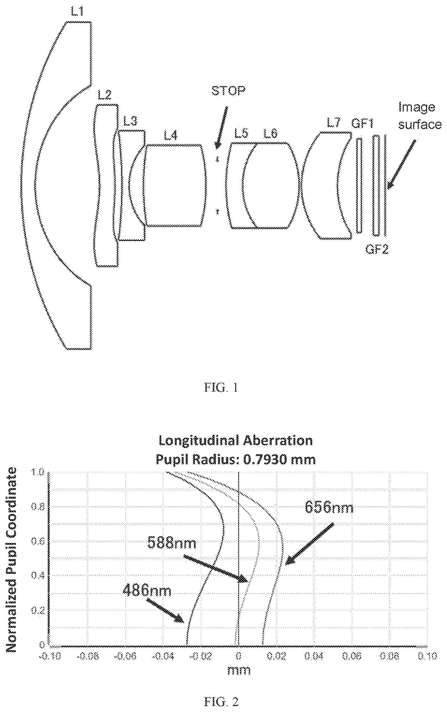
is a schematic diagram of a structure of a camera optical lens LA according to Embodiment 1 of the present disclosure.
is a schematic diagram of a longitudinal aberration of the camera optical lens LA according to Embodiment 1 of the present disclosure.
is a schematic diagram of a field curvature and a distortion of the camera optical lens LA according to Embodiment 1 of the present disclosure.
is a schematic diagram of a lateral color of the camera optical lens LA according to Embodiment 1 of the present disclosure.
is a schematic diagram of a structure of a camera optical lens LA according to Embodiment 2 of the present disclosure.
is a schematic diagram of a longitudinal aberration of the camera optical lens LA according to Embodiment 2 of the present disclosure.
is a schematic diagram of a field curvature and a distortion of the camera optical lens LA according to Embodiment 2 of the present disclosure.
is a schematic diagram of a lateral color of the camera optical lens LA according to Embodiment 2 of the present disclosure.
is a schematic diagram of a structure of a camera optical lens LA according to Embodiment 3 of the present disclosure.
is a schematic diagram of a longitudinal aberration of the camera optical lens LA according to Embodiment 3 of the present disclosure.
is a schematic diagram of a field curvature and a distortion of the camera optical lens LA according to Embodiment 3 of the present disclosure.
is a schematic diagram of a lateral color of the camera optical lens LA according to Embodiment 3 of the present disclosure.
DETAILED DESCRIPTION OF EMBODIMENTS
The present disclosure will be further described with reference to the accompanying drawings and embodiments. To make the objects, technical solutions, and advantages of the present disclosure clearer, embodiments of the present disclosure are described in detail with reference to accompanying drawings in the following. A person of ordinary skill in the art can understand that, in the embodiments of the present disclosure, many technical details are provided to make readers better understand the present disclosure. However, even without these technical details and any changes and modifications based on the following embodiments, technical solutions required to be protected by the present disclosure can be implemented.
Embodiments of the camera optical lens will be described herein. The camera optical lens LA has a lens system including seven lenses, in which, from the object side to the image side in sequence, a first lens L 1 , a second lens L 2 , a third lens L 3 , a fourth lens L 4 , a fifth lens L 5 , a sixth lens L 6 and a seventh lens L 7 are provided. Glass plates GF are disposed between the seventh lens L 7 and an image surface. The glass plates GF may include glass cover plates, various filters, and the like. In the present disclosure, the glass plates GF may be disposed at different positions or may be omitted. In addition, the first lens L 1 , the second lens L 2 , the third lens L 3 , the fourth lens L 4 , the fifth lens L 5 , the sixth lens L 6 and the seventh lens L 7 are also made from glass material.
The first lens L 1 has a negative refractive power, the second lens L 2 has a negative refractive power, the third lens L 3 has a negative refractive power, the fourth lens L 4 has a positive refractive power, the fifth lens L 5 has a negative refractive power, the sixth lens L 6 has a positive refractive power, and the seventh lens L 7 has a positive refractive power. For batter correction to various distortions, it is desirable that surfaces of the second lens L 2 and the seventh lens L 7 are aspheric.
The camera optical lens LA satisfies a condition of: −50.10≤ f 2/ f≤− 22.90 (1)
Condition (1) specifies a ratio of a focal length f2 of the second lens L 2 to a focal length f of the camera optical lens LA. Within this condition, correction to various distortions is facilitated when the FNO is 1.83.
The camera optical lens LA satisfies a condition of: 9.20≤ d 2/ d 4≤30.00 (2)
Condition (2) specifies a ratio of an on-axis distance d2 from an image-side surface S 2 of the first lens L 1 to an object-side surface S 3 of the second lens L 2 to an on-axis distance d4 from the image-side surface S 4 of the second lens L 2 to the object-side surface S 5 of the third lens L 3 . Within this condition, correction to various distortions is facilitated when the FNO is 1.83.
The camera optical lens LA satisfies a condition of: −11.10≤ R 5/ f≤− 9.55 (3)
Condition (3) specifies a ratio of a central curvature radius R5 of an object-side surface S 5 of the third lens L 3 to the focal length f of the camera optical lens LA. Within this condition, correction to various distortions is facilitated when the FNO is 1.83.
The camera optical lens LA satisfies a condition of: −753.70≤ f 2/ d 4≤−109.00 (4)
Condition (4) specifies a ratio of the focal length f2 of the second lens L 2 to the on-axis distance d4 from the image-side surface S 4 of the second lens L 2 to the object-side surface S 5 of the third lens L 3 . Within this condition, correction to various distortions is facilitated when the FNO is 1.83.
The camera optical lens LA satisfies a condition of: 4.60≤ f 2/ R 4≤14.60 (5)
Condition (5) specifies a ratio of the focal length f2 of the second lens L 2 to a central curvature radius R4 of an image-side surface S 4 of the second lens L 2 . Within this condition, correction to various distortions is facilitated when the FNO is 1.83.
The camera optical lens LA satisfies a condition of: −25.00≤ f 2/ f 6≤−12.00 (6)
Condition (6) specifies a ratio of the focal length f2 of the second lens L 2 to a focal length f6 of the sixth lens L 6 . Within this condition, correction to various distortions is facilitated when the FNO is 1.83.
With the seven lenses included in the camera optical lens LA satisfying the aforementioned structure and conditions respectively, the camera optical lens LA is obtained which is suitable for a surround-sensing camera, has a suitable field angle and excellent optical performance and has a FNO less than 1.83.
EMBODIMENTS
The camera optical lens LA will be further described with reference to the following examples. Symbols used in various examples are shown as follows. It should be noted that the distance, central curvature radius, and on-axis thickness are all in units of millimeter (mm).
•
• f: focal length of the camera optical lens LA; • f1: focal length of the first lens L 1 ; • f2: focal length of the second lens L 2 ; • f3: focal length of the third lens L 3 ; • f4: focal length of the fourth lens L 4 ; • f5: focal length of the fifth lens L 5 ; • f6: focal length of the sixth lens L 6 ; • f7: focal length of the seventh lens L 7 ; • FNO: F number (ratio of an effective focal length and an entrance pupil diameter of the camera optical lens); • 2ω: full viewing angle; • STOP: aperture; • R: central curvature radius of an optical surface; • R1: central curvature radius of the object-side surface S 1 of the first lens L 1 ; • R2: central curvature radius of the image-side surface S 2 of the first lens L 1 ; • R3: central curvature radius of the object-side surface S 3 of the second lens L 2 ; • R4: central curvature radius of the image-side surface S 4 of the second lens L 2 ; • R5: central curvature radius of the object-side surface S 5 of the third lens L 3 ; • R6: central curvature radius of the image-side surface S 6 of the third lens L 3 ; • R7: central curvature radius of the object-side surface S 7 of the fourth lens L 4 ; • R8: central curvature radius of the image-side surface S 8 of the fourth lens L 4 ; • R9: central curvature radius of the object-side surface S 9 of the fifth lens L 5 ; • R10: central curvature radius of the image-side surface S 10 of the fifth lens L 5 and central curvature radius of the object-side surface S 10 of the sixth lens L 6 ; • R11: central curvature radius of the image-side surface S 11 of the sixth lens L 6 ; • R12: central curvature radius of the object-side surface S 12 of the seventh lens L 7 ; • R13: central curvature radius of the image-side surface S 13 of the seventh lens L 7 ; • R14: central curvature radius of an object-side surface S 14 of the glass plate GF 1 ; • R15: central curvature radius of an image-side surface S 15 of the glass plate GF 1 ; • R16: central curvature radius of an object-side surface S 16 of the glass plate GF 2 ; • R17: central curvature radius of an image-side surface 5157 of the glass plate GF 2 ; • d: on-axis thickness of a lens or an on-axis distance between lenses; • d1: on-axis thickness of the first lens L 1 ; • d2: on-axis distance from the image-side surface S 2 of the first lens L 1 to the object-side surface S 3 of the second lens L 2 ; • d3: on-axis thickness of the second lens L 2 ; • d4: on-axis distance from the image-side S 4 surface of the second lens L 2 to the object-side surface S 5 of the third lens L 3 ; • d5: on-axis thickness of the third lens L 3 ; • d6: on-axis distance from the image-side surface S 6 of the third lens L 3 to the object-side surface S 7 of the fourth lens L 4 ; • d7: on-axis thickness of the fourth lens L 4 ; • d8: on-axis distance from the image-side surface S 8 of the fourth lens L 4 to the aperture STOP; • d9: on-axis distance from the aperture STOP to the object-side surface S 9 of the fifth lens L 5 ; • d10: on-axis thickness of the fifth lens L 5 ; • d11: on-axis thickness of the sixth lens L 6 ; • d12: on-axis distance from the image-side surface S 11 of the sixth lens L 6 to the object-side surface S 12 of the seventh lens L 7 ; • d13: on-axis thickness of the seventh lens L 7 ; • d14: on-axis distance from the image-side surface S 13 of the seventh lens L 7 to the object-side surface S 14 of the glass plate GF 1 ; • d15: on-axis thickness of the glass plate GF 1 ; • d16: on-axis distance from the image-side surface S 15 of the glass plate GF 1 to the object-side surface S 16 of the glass plate GF 2 ; • d17: on-axis thickness of the glass plate GF 2 ; • d18: on-axis distance from the image-side surface S 17 of the glass plate GF 2 to the image surface; • nd: refractive index of the d line; • nd1: refractive index of the d line of the first lens L 1 ; • nd2: refractive index of the d line of the second lens L 2 ; • nd3: refractive index of the d line of the third lens L 3 ; • nd4: refractive index of the d line of the fourth lens L 4 ; • nd5: refractive index of the d line of the fifth lens L 5 ; • nd6: refractive index of the d line of the sixth lens L 6 ; • nd7: refractive index of the d line of the seventh lens L 7 ; • nd8: refractive index of the d line of the glass plate GF 1 ; • nd9: refractive index of the d line of the glass plate GF 2 ; • νd: abbe number; • ν1: abbe number of the first lens L 1 ; • ν2: abbe number of the second lens L 2 ; • ν3: abbe number of the third lens L 3 ; • ν4: abbe number of the fourth lens L 4 ; • ν5: abbe number of the fifth lens L 5 ; • ν6: abbe number of the sixth lens L 6 ; • ν7: abbe number of the seventh lens L 7 ; • ν8: abbe number of the glass plate GF 1 ; • ν9: abbe number of the glass plate GF 2 ; • TTL: total optical length of the camera optical lens (on-axis distance from the object-side surface S 1 of the first lens L 1 to the image surface of the camera optical lens) in mm; • LB: on-axis distance from the image-side surface S 13 of the seventh lens L 7 to the image surface (including the thicknesses of the glass plates GF); • IH: image high.
Embodiment 1
is a schematic diagram of a structure of the camera optical lens LA according to Embodiment 1 of the present disclosure. Table 1 shows the central curvature radiuses R of the object-side surfaces and the image-side surfaces of the camera optical lens LA of the first lens L 1 to the seventh lens L 7 , the on-axis thicknesses d of the lenses, the on-axis distances d between the lenses, the refractive indexes nd and the abbe numbers νd. Table 2 shows the conic coefficients k and the aspheric surface coefficients. Table 3 shows values of 2ω, Fno, f, f1, f2, f3, f4, f5, f6, f7, TTL, LB and IH.
TABLE 1
Effective
R d nd νd radius (mm)
S1 R1 23.14014 d1 1.218 nd1 1.6510 ν1 56.24 12.943
S2 R2 8.89087 d2 5.659 7.934
S3 R3 −10.00610 d3 1.358 nd2 1.5831 ν2 59.37 6.405
S4 R4 −14.15104 d4 0.609 4.527
S5 R5 −31.25937 d5 0.629 nd3 1.6180 ν3 63.32 4.339
S6 R6 4.37867 d6 1.269 3.191
S7 R7 17.92240 d7 5.499 nd4 1.8081 ν4 22.76 3.185
S8 R8 −11.05510 d8 1.014 2.547
STOP STOP ∞(Infinity) d9 0.748 1.962
S9 R9 11.77016 d10 1.450 nd5 1.9591 ν5 17.47 2.324
S10 R10 4.99876 d11 4.977 nd6 1.5952 ν6 67.74 2.463
S11 R11 −6.05390 d12 0.199 3.347
S12 R12 5.62000 d13 3.170 nd7 1.5831 ν7 59.37 4.030
S13 R13 6.67583 d14 1.702 3.576
S14 R14 ∞ d15 0.400 nd8 1.5168 ν8 64.20 3.681
S15 R15 ∞ d16 1.056 3.723
S16 R16 ∞ d17 0.500 nd9 1.5168 ν9 64.20 3.891
S17 R17 ∞ d18 0.550 3.944
Reference wavelength = 588 nm
TABLE 2
Conic
coefficient Aspheric surface coefficients
k A4 A6 A8 A10
R3 0.0000000E+00 1.7141842E−03 −1.4200034E−05 7.4274515E−08 0.0000000E+00
R4 0.0000000E+00 2.1344431E−03 −1.0922261E−05 8.6787095E−07 5.7317018E−09
R12 4.8210538E−02 −8.0277970E−04 2.8586590E−06 9.3417374E−08 −6.1986286E−09
R13 4.1523018E−01 −4.8611796E−04 −1.1959800E−06 5.0440347E−07 9.9641583E−08
Conic
coefficient Aspheric surface coefficients
k A12 A14 A16
R3 0.0000000E+00 0.0000000E+00 0.0000000E+00 0.0000000E+00
R4 0.0000000E+00 0.0000000E+00 0.0000000E+00 0.0000000E+00
R12 4.8210538E−02 0.0000000E+00 0.0000000E+00 0.0000000E+00
R13 4.1523018E−01 0.0000000E+00 0.0000000E+00 0.0000000E+00
Herein, k denotes a conic coefficient, A4, A6, A8, A10, A12, A14 and A16 denote aspheric surface coefficients. y =( x 2 /R )/[1+{1−( k+ 1)( x 2 /R 2 )} 1/2 ]+A 4 x 4 +A 6 x 6 +A 8 x 8 +A 10 x 10 +A 12 x 12 +A 14 x 14 +A 66 x 16 (7)
Herein, x denotes a vertical distance between a point in the aspheric curve and the optical axis, and y denotes an aspheric depth (i.e. a vertical distance between the point having a distance of x from the optical axis and a plane tangent to the vertex on the optical axis of the aspheric surface).
For convenience, an aspheric surface of each lens surface uses the aspheric surfaces shown in the above formula (7). However, the present disclosure is not limited to the aspherical polynomials form shown in the formula (7).
TABLE 3
2ω (°) 194.9
FNO 1.83
f (mm) 2.899
f1 (mm) −22.881
f2 (mm) −66.441
f3 (mm) −6.155
f4 (mm) 9.177
f5 (mm) −10.025
f6 (mm) 5.516
f7 (mm) 28.821
TTL (mm) 32.006
LB (mm) 4.209
IH (mm) 4.032
In the subsequent Table 10, various parameters of Embodiments 1, 2 and 3 and values corresponding to the parameters specified in the above conditions (1) to (6) are shown.
As shown in Table 10, Embodiment 1 satisfies the conditions (1) to (6).
to 4 show a longitudinal aberration, a field curvature, a distortion and a lateral color of the camera optical lens LA according to Embodiment 1. and illustrates the longitudinal aberration and the lateral color of light with wavelengths of 486 nm, 588 nm and 656 nm after passing the camera optical lens LA, respectively. illustrates a field curvature and a distortion with a wavelength of 588 nm after passing the camera optical lens LA. A field curvature S in the drawings is a field curvature in a sagittal direction, and T is a field curvature in a tangential direction, which are also the same in Embodiments 2 and 3. It can be seen that the camera optical lens LA of Embodiment 1 becomes bright when FNO=1.83 as shown in Table 3, and has good optical performance as shown in to 4 .
Embodiment 2
is a schematic diagram of a structure of the camera optical lens LA according to Embodiment 2 of the present disclosure. Table 4 shows the central curvature radiuses R of the object-side surfaces and the image-side surfaces of the camera optical lens LA of the first lens L 1 to the seventh lens L 7 , the on-axis thicknesses d of the lenses, the on-axis distances d between the lenses, the refractive indexes nd and the abbe numbers νd. Table 5 shows the conic coefficients k and the aspheric surface coefficients. Table 6 shows values of 2ω, Fno, f, f1, f2, f3, f4, f5, f6, f7, TTL, LB and IH.
TABLE 4
Effective
R d nd νd radius (mm)
S1 R1 23.14014 d1 1.200 nd1 1.6510 ν1 56.24 11.780
S2 R2 7.69289 d2 5.403 6.923
S3 R3 −7.95251 d3 1.193 nd2 1.5831 ν2 59.37 5.914
S4 R4 −9.32706 d4 0.180 4.700
S5 R5 −25.98132 d5 1.367 nd3 1.6180 ν3 63.32 4.579
S6 R6 5.00627 d6 1.220 3.173
S7 R7 46.46123 d7 4.237 nd4 1.8081 ν4 22.76 3.100
S8 R8 −11.65932 d8 1.595 3.100
STOP STOP ∞ d9 1.485 1.856
S9 R9 7.92902 d10 1.563 nd5 1.9591 ν5 17.47 3.711
S10 R10 4.48000 d11 5.370 nd6 1.5952 ν6 67.74 2.296
S11 R11 −6.70364 d12 0.278 2.296
S12 R12 5.61157 d13 2.881 nd7 1.5831 ν7 59.37 3.659
S13 R13 7.20542 d14 1.702 3.513
S14 R14 ∞ d15 0.400 nd8 1.5168 ν8 64.20 3.664
S15 R15 ∞ d16 0.885 3.713
S16 R16 ∞ d17 0.500 nd9 1.5168 ν9 64.20 3.874
S17 R17 ∞ d18 0.550 3.934
Reference wavelength = 588 nm
TABLE 5
Conic
coefficient Aspheric surface coefficients
k A4 A6 A8 A10
R3 0.0000000E+00 2.4765340E−03 −3.4792300E−05 2.9860600E−07 1.1223400E−09
R4 0.0000000E+00 2.6303960E−03 −2.7158800E−05 7.8263500E−08 −1.3738500E−08
R12 1.8899425E−01 −8.1248600E−04 −2.4852800E−05 −1.0904900E−06 −6.1016100E−09
R13 1.3280726E+00 −1.3104200E−05 −4.9259200E−05 −1.9444600E−06 −1.0010000E−07
Conic
coefficient Aspheric surface coefficients
k A12 A14 A16
R3 0.0000000E+00 1.4821300E−13 0.0000000E+00 0.0000000E+00
R4 0.0000000E+00 5.8033800E−10 0.0000000E+00 0.0000000E+00
R12 1.8899425E−01 −1.1519200E−10 0.0000000E+00 0.0000000E+00
R13 1.3280726E+00 5.6849300E−09 0.0000000E+00 0.0000000E+00
TABLE 6
2ω(°) 194.8
FNO 1.83
f (mm) 2.715
f1 (mm) −18.203
f2 (mm) −135.743
f3 (mm) −6.660
f4 (mm) 11.831
f5 (mm) −13.681
f6 (mm) 5.484
f7 (mm) 26.015
TTL (mm) 32.009
LB (mm) 6.368
IH (mm) 4.032
As shown in Table 10, Embodiment 2 satisfies the conditions (1) to (6).
to 8 show a longitudinal aberration, a field curvature, a distortion and a lateral color of the camera optical lens LA according to Embodiment 2. and illustrates the longitudinal aberration and the lateral color of light with wavelengths of 486 nm, 588 nm and 656 nm after passing the camera optical lens LA, respectively. illustrates a field curvature and a distortion with a wavelength of 588 nm after passing the camera optical lens LA. It can be seen that the camera optical lens LA of Embodiment 2 becomes bright when FNO=1.83 as shown in Table 6, and has good optical performance as shown in to 8 .
Embodiment 3
is a schematic diagram of a structure of the camera optical lens LA according to Embodiment 3 of the present disclosure. Table 7 shows the central curvature radiuses R of the object-side surfaces and the image-side surfaces of the camera optical lens LA of the first lens L 1 to the seventh lens L 7 , the on-axis thicknesses d of the lenses, the on-axis distances d between the lenses, the refractive indexes nd and the abbe numbers νd. Table 8 shows the conic coefficients k and the aspheric surface coefficients. Table 9 shows values of 2ω, Fno, f, f1, f2, f3, f4, f5, f6, f7, TTL, LB and IH.
TABLE 7
Effective
R d nd νd radius (mm)
S1 R1 23.14014 d1 1.000 nd1 1.6510 ν1 56.24 12.108
S2 R2 8.08847 d2 5.567 7.286
S3 R3 −8.72203 d3 1.186 nd2 1.5831 ν2 59.37 6.197
S4 R4 −10.73572 d4 0.293 4.900
S5 R5 −29.40532 d5 1.274 nd3 1.6180 ν3 63.32 4.675
S6 R6 4.98199 d6 1.447 3.221
S7 R7 118.39558 d7 3.791 nd4 1.8081 ν4 22.76 3.100
S8 R8 −10.91943 d8 1.894 3.100
STOP STOP ∞ d9 1.516 1.845
S9 R9 8.02630 d10 1.795 nd5 1.9591 ν5 17.47 3.711
S10 R10 4.48000 d11 5.571 nd6 1.5952 ν6 67.74 2.286
S11 R11 −6.70166 d12 0.127 3.127
S12 R12 5.79762 d13 3.111 nd7 1.5831 ν7 59.37 3.733
S13 R13 7.83168 d14 1.702 3.608
S14 R14 ∞ d15 0.400 nd8 1.5168 ν8 64.20 3.770
S15 R15 ∞ d16 0.785 3.817
S16 R16 ∞ d17 0.500 nd9 1.5168 ν9 64.20 3.959
S17 R17 ∞ d18 0.550 4.019
Reference wavelength = 588 nm
TABLE 8
Conic
coefficient Aspheric surface coefficients
k A4 A6 A8 A10
R3 0.0000000E+00 2.3156276E−03 −3.6344213E−05 2.8306112E−07 1.3077852E−09
R4 0.0000000E+00 2.4638836E−03 −3.2011495E−05 2.3595106E−07 −2.0940165E−08
R12 2.1829796E−01 −8.2730871E−04 −2.2275287E−05 −9.6586968E−07 −1.3710673E−08
R13 1.9080438E+00 −2.2884181E−04 −6.3562126E−05 −1.9807239E−07 −1.6277323E−07
Conic
coefficient Aspheric surface coefficients
k A12 A14 A16
R3 0.0000000E+00 −1.3743541E−11 1.5218248E−13 0.0000000E+00
R4 0.0000000E+00 3.4937713E−10 8.5215433E−12 0.0000000E+00
R12 2.1829796E−01 3.7150559E−10 3.4637898E−11 0.0000000E+00
R13 1.9080438E+00 −1.0992431E−09 6.1481692E−10 0.0000000E+00
TABLE 9
2ω(°) 194.8
FNO 1.83
f (mm) 2.673
f1 (mm) −19.553
f2 (mm) −101.577
f3 (mm) −6.778
f4 (mm) 12.439
f5 (mm) −13.936
f6 (mm) 5.528
f7 (mm) 24.393
TTL (mm) 32.509
LB (mm) 6.498
IH (mm) 4.032
As shown in Table 10, Embodiment 3 satisfies the conditions (1) to (6).
to 12 show a longitudinal aberration, a field curvature, a distortion and a lateral color of the camera optical lens LA according to Embodiment 3. and illustrates the longitudinal aberration and the lateral color of light with wavelengths of 486 nm, 588 nm and 656 nm after passing the camera optical lens LA, respectively. illustrates a field curvature and a distortion with a wavelength of 588 nm after passing the camera optical lens LA. It can be seen that the camera optical lens LA of Embodiment 3 becomes bright when FNO=1.83 as shown in Table 9, and has good optical performance as shown in to 12 .
TABLE 10
Embodiment 1 Embodiment 2 Embodiment 3
Condition (1) −22.919 −50.000 −37.998
Condition (2) 9.290 29.999 19.018
Condition (3) −10.783 −9.570 −11.000
Condition (4) −109.066 −753.635 −347.016
Condition (5) 4.695 14.554 9.462
Condition (6) −12.046 −24.754 −18.374
It will be understood by those of ordinary skill in the art that the embodiments described above are specific embodiments realizing the present disclosure, and that in practical applications, various changes may be made thereto in form and in detail without departing from the range and scope of the disclosure.
Figures (6)
Citations
This patent cites (4)
- US20060274433
- US20190219795
- US20190324232
- US20200142158