Abstract
The present disclosure relates to a technical field of optical lenses, and discloses a camera optical lens. The camera optical lens includes six lenses. An order of the seven lenses is sequentially from an object side to an image side, which is shown as follows: a first lens having a positive refractive power, a second lens having a negative refractive power, a third lens having a refractive power, a fourth lens having a negative refractive power, a fifth lens having a positive refractive power, and a sixth lens having a negative refractive power. While the camera optical lens has good optical performance, the camera optical lens further meets design requirements of large aperture, wide-angle, and ultra-thinness. In addition, on-axis and off-axis chromatic aberrations are fully corrected and the camera optical lens has excellent optical characteristics.
Claims (10)
1. A camera optical lens, comprising: six lenses, being sequentially from an object side to an image side, comprising: a first lens having a positive refractive power; a second lens having a negative refractive power; a third lens having a refractive power; a fourth lens having a negative refractive power; a fifth lens having a positive refractive power; and a sixth lens having a negative refractive power; wherein, an abbe number of the first lens is denoted as v1, a focal length of the camera optical lens is denoted as f, a focal length of the second lens is denoted as f2, a focal length of the fourth lens is denoted as f4, a center curvature radius of an object side surface of the fifth lens is denoted as R 9 , a center curvature radius of an image side surface of the fifth lens is denoted as R 10 , an on-axis thickness of the first lens is denoted as d1, an on-axis distance, from an image side surface of the first lens to an object side surface of the second lens, is denoted as d2, and the camera optical satisfies following relationships: 63.00≤ v 1≤82.00; −6.50≤ f 2/ f≤− 3.00; −10.00≤ f 4/ f≤− 5.00; −30.00≤ R 9/ R 10≤−2.50; 1.50≤ d 1/ d 2≤5.00.
Show 9 dependent claims
2. The camera optical lens according to claim 1 , wherein a center curvature radius of an object side surface of the third lens is denoted as R 5 , a center curvature radius of an image side surface of the third lens is denoted as R 6 , and the camera optical lens satisfies a following relationship: 3.00≤( R 5+ R 6)/( R 5− R 6)≤20.00.
3. The camera optical lens according to claim 1 , wherein an object side surface of the first lens is convex in a paraxial region, the image side surface of the first lens is concave in a paraxial region; a focal length of the first lens is denoted as f1, a center curvature radius of the object side surface of the first lens is denoted as R 1 , a center curvature radius of the image side surface of the first lens is denoted as R 2 , a total optical length of the camera optical lens is denoted as TTL, and the camera optical lens satisfies following relationships: 0.49≤ f 1/ f≤ 1.55; −4.85≤( R 1+ R 2)/( R 1− R 2)≤−1.09; 0.06≤ d 1/ TTL≤ 0.21.
4. The camera optical lens according to claim 1 , wherein an image side surface of the second lens is concave in a paraxial region; a center curvature radius of the object side surface of the second lens is denoted as R 3 , a center curvature radius of the image side surface of the second lens is denoted as R 4 , an on-axis thickness of the second lens is denoted as d3, a total optical length of the camera optical lens is denoted as TTL, and the camera optical lens satisfies following relationships: −1.79≤( R 3+ R 4)/( R 3− R 4)≤8.52; 0.02≤ d 3/ TTL≤ 0.07.
5. The camera optical lens according to claim 1 , wherein a focal length of the third lens is denoted as f3, an on-axis thickness of the third lens is denoted as d5, a total optical length of the camera optical lens is denoted as TTL, and the camera optical lens satisfies following relationships: −254.51 f 3/ f≤ 808.00; 0.03≤ d 5/ TTL≤ 0.11.
6. The camera optical lens according to claim 1 , wherein an object side surface of the fourth lens is convex in a paraxial region, an image side surface of the fourth lens is concave in a paraxial region; a center curvature radius of the object side surface of the fourth lens is denoted as R 7 , a center curvature radius of the image side surface of the fourth lens is denoted as R 8 , an on-axis thickness of the fourth lens is denoted as d7, a total optical length of the camera optical lens is denoted as TTL, and the camera optical lens satisfies following relationships: 2.22≤( R 7+ R 8)/( R 7− R 8)≤22.28; 0.03≤ d 7/ TTL≤ 0.09.
7. The camera optical lens according to claim 1 , wherein the object side surface of the fifth lens is convex in a paraxial region, the image side surface of the fifth lens is convex in a paraxial region; a focal length of the fifth lens is denoted as f5, an on-axis thickness of the fifth lens is denoted as d9, a total optical length of the camera optical lens is denoted as TTL, and the camera optical lens satisfies following relationships: 0.32≤ f 5/ f≤ 1.06; 0.06≤ d 9/ TTL≤ 0.23.
8. The camera optical lens according to claim 1 , wherein an object side surface of the sixth lens is concave in a paraxial region, an image side surface of the sixth lens is concave in a paraxial region; a focal length of the sixth lens is denoted as f6, a center curvature radius of the object side surface of the sixth lens is denoted as R 11 , a center curvature radius of the image side surface of the sixth lens is denoted as R 12 , an on-axis thickness of the sixth lens is denoted as d11, a total optical length of the camera optical lens is denoted as TTL, and the camera optical lens satisfies following relationships: −1.30≤ f 6/ f≤− 0.36; 0.20≤( R 11+ R 12)/( R 11− R 12)≤0.76; 0.04≤ d 11/ TTL≤ 0.12.
9. The camera optical lens according to claim 1 , wherein an image height of the camera optical lens is denoted as IH, a total optical length of the camera optical lens is denoted as TTL, and the camera optical lens satisfies a following relationship: TTL/IH≤ 1.30.
10. The camera optical lens according to claim 1 , wherein the first lens is made of a glass material.
Full Description
Show full text →
TECHNICAL FIELD
The present disclosure relates to the field of optical lens, and in particular to a camera optical lens suitable for handheld devices, such as smart phones, digital cameras, and imaging devices, such as monitors or PC lenses.
BACKGROUND
With emergence of smart phones in recent years, demand for miniature camera lens is increasing day by day, and because a pixel size of per photosensitive device shrinks, in addition a development trend of electronic products with good functions, and thin and portable appears, therefore, a miniaturized camera optical lens having good imaging quality becomes a mainstream in current market. In order to obtain better imaging quality, multi-piece lens structure is mainly adopted. Moreover, with development of technology and increases of diversified needs of users, a pixel area of per photosensitive device is constantly shrinking, and requirements of optical systems for imaging quality are constantly increasing. A six-piece lens structure gradually appears in lens design. There is an urgent need for a wide-angled camera optical lens having excellent optical characteristics, a small size, and fully corrected aberrations.
SUMMARY
Aiming at above problems, the present disclosure seeks to provide a camera optical lens, which has good optical performance and meets design requirements of large aperture, ultra-thinness, and wide-angle.
In order to solve the above problems, embodiments of the present disclosure provide a camera optical lens. The camera optical lens includes seven lenses. An order of the seven lenses is sequentially from an object side to an image side, which is shown as follows: a first lens having a positive refractive power, a second lens having a negative refractive power, a third lens having a refractive power, a fourth lens having a negative refractive power, a fifth lens having a positive refractive power, and a sixth lens having a negative refractive power. An abbe number of the first lens is denoted as v1, a focal length of the camera optical lens is denoted as f, a focal length of the second lens is denoted as f2, a focal length of the fourth lens is denoted as f4, a center curvature radius of an object side surface of the fifth lens is denoted as R 9 , a center curvature radius of an image side surface of the fifth lens is denoted as R 10 , an on-axis thickness of the first lens is denoted as d1, an on-axis distance, from an image side surface of the first lens to an object side surface of the second lens, is denoted as d2, and the camera optical lens satisfies following relationships: 63.00 ≤v 1≤82.00; −6.50≤ f 2/ f≤− 3.00; −10.00≤ f 4/ f≤− 5.00; −30.00≤ R 9/ R 10≤−2.50; 1.50≤≤ d 1/ d 2≤5.00.
As an improvement, a center curvature radius of an object side surface of the third lens is denoted as R 5 , a center curvature radius of an image side surface of the third lens is denoted as R 6 , and the camera optical lens satisfies a following relationship: 3.00≤( R 5+ R 6)/( R 5− R 6)≤20.00.
As an improvement, an object side surface of the first lens is convex in a paraxial region, the image side surface of the first lens is concave in a paraxial region. A focal length of the first lens is denoted as f1, a center curvature radius of the object side surface of the first lens is denoted as R 1 , a center curvature radius of the image side surface of the first lens is denoted as R 2 , a total optical length of the camera optical lens is denoted as TTL, and the camera optical lens satisfies following relationships: 0.49≤ f 1/ f≤ 1.55; −4.85≤( R 1+ R 2)/( R 1− R 2)≤−1.09; 0.06≤ d 1/ TTL≤ 0.21.
As an improvement, an image side surface of the second lens is concave in a paraxial region. A center curvature radius of the object side surface of the second lens is denoted as R 3 , a center curvature radius of the image side surface of the second lens is denoted as R 4 , an on-axis thickness of the second lens is denoted as d3, a total optical length of the camera optical lens is denoted as TTL, and the camera optical lens satisfies following relationships: −1.79≤( R 3+ R 4)/( R 3− R 4)≤8.52; 0.02≤ d 3/ TTL≤ 0.07.
As an improvement, a focal length of the third lens is denoted as f3, an on-axis thickness of the third lens is denoted as d5, a total optical length of the camera optical lens is denoted as TTL, and the camera optical lens satisfies following relationships: −254.51 f 3/ f≤ 808.00; 0.03≤ d 5/ TTL≤ 0.11.
As an improvement, an object side surface of the fourth lens is convex in a paraxial region, an image side surface of the fourth lens is concave in a paraxial region. A center curvature radius of the object side surface of the fourth lens is denoted as R 7 , a center curvature radius of the image side surface of the fourth lens is denoted as R 8 , an on-axis thickness of the fourth lens is denoted as d7, a total optical length of the camera optical lens is denoted as TTL, and the camera optical lens satisfies following relationships: 2.22≤( R 7+ R 8)/( R 7− R 8)≤22.28; 0.03≤ d 7/ TTL≤ 0.09.
As an improvement, the object side surface of the fifth lens is convex in a paraxial region, the image side surface of the fifth lens is convex in a paraxial region. A focal length of the fifth lens is denoted as f5, an on-axis thickness of the fifth lens is denoted as d9, a total optical length of the camera optical lens is denoted as TTL, and the camera optical lens satisfies following relationships: 0.32≤ f 5/ f≤ 1.06; 0.06≤ d 9/ TTL≤ 0.23.
As an improvement, an object side surface of the sixth lens is concave in a paraxial region, an image side surface of the sixth lens is concave in a paraxial region. A focal length of the sixth lens is denoted as f6, a center curvature radius of the object side surface of the sixth lens is denoted as R 11 , a center curvature radius of the image side surface of the sixth lens is denoted as R 12 , an on-axis thickness of the sixth lens is denoted as d11, a total optical length of the camera optical lens is denoted as TTL, and the camera optical lens satisfies following relationships: −1.30≤ f 6/ f≤− 0.36; 0.20≤( R 11+ R 12)/( R 11− R 12)≤0.76; 0.04≤ d 11/ TTL≤ 0.12.
As an improvement, an image height of the camera optical lens is denoted as IH, a total optical length of the camera optical lens is denoted as TTL, and the camera optical lens satisfies a following relationship: TTL/IH≤ 1.30.
As an improvement, the first lens is made of a glass material.
The beneficial effects of the present disclosure are as follows. The camera optical lens provided by the present disclosure has excellent optical characteristics, and further has characteristics of large aperture, wide-angle, and ultra-thin, especially suitable for mobile phone camera lens assemblies and WEB camera lenses, which are composed of camera components having high pixels, such as CCD and CMOS.
BRIEF DESCRIPTION OF DRAWINGS
To more clearly illustrate the technical solutions in the embodiments of the present disclosure clearer, accompanying drawings that need to be used in the description of the embodiments will briefly introduce in following. Obviously, the drawings described below are only some embodiments of the present disclosure. For A person of ordinary skill in the art, other drawings can be obtained according to these without creative labor, wherein:
is a schematic diagram of a structure of a camera optical lens according to a first embodiment of the present disclosure.
is a schematic diagram of a longitudinal aberration of the camera optical lens shown in .
is a schematic diagram of a lateral color of the camera optical lens shown in .
is a schematic diagram of a field curvature and a distortion of the camera optical lens shown in .
is a schematic diagram of a structure of a camera optical lens according to a second embodiment of the present disclosure.
is a schematic diagram of a longitudinal aberration of the camera optical lens shown in .
is a schematic diagram of a lateral color of the camera optical lens shown in .
is a schematic diagram of a field curvature and a distortion of the camera optical lens shown in .
is a schematic diagram of a structure of a camera optical lens according to a third embodiment of the present disclosure.
is a schematic diagram of a longitudinal aberration of the camera optical lens shown in .
is a schematic diagram of a lateral color of the camera optical lens shown in .
is a schematic diagram of a field curvature and a distortion of the camera optical lens shown in .
is a schematic diagram of a structure of a camera optical lens according to a fourth embodiment of the present disclosure.
is a schematic diagram of a longitudinal aberration of the camera optical lens shown in .
is a schematic diagram of a lateral color of the camera optical lens shown in .
is a schematic diagram of a field curvature and a distortion of the camera optical lens shown in .
is a schematic diagram of a structure of a camera optical lens according to a comparative embodiment of the present disclosure.
is a schematic diagram of a longitudinal aberration of the camera optical lens shown in .
is a schematic diagram of a lateral color of the camera optical lens shown in .
is a schematic diagram of a field curvature and a distortion of the camera optical lens shown in .
DETAILED DESCRIPTION OF EMBODIMENTS
In order to make objects, technical solutions, and advantages of the present disclosure clearer, embodiments of the present disclosure are described in detail with reference to accompanying drawings in following. A person of ordinary skill in the art can understand that, in the embodiments of the present disclosure, many technical details are provided to make readers better understand the present disclosure. However, even without these technical details and any changes and modifications based on the following embodiments, technical solutions required to be protected by the present disclosure can be implemented.
Embodiment 1
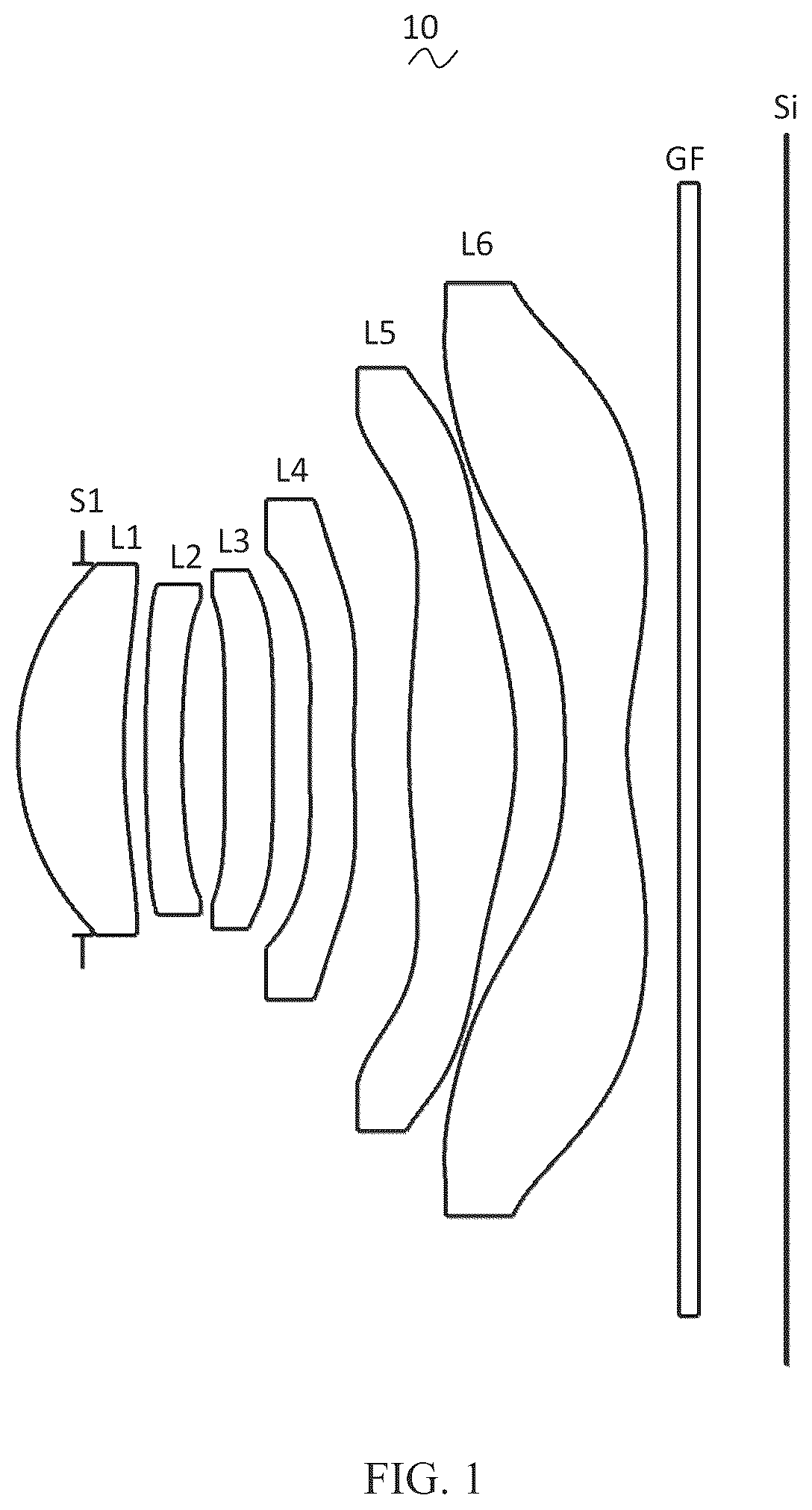
Referring to the drawings, the present disclosure provides a camera optical lens 10 . shows a structure of the camera optical lens 10 of a first embodiment of the present disclosure. The camera optical lens 10 includes six lenses. Specifically, an order of the camera optical lens 10 is sequentially from an object side to an image side, which is shown as follows: an aperture S 1 , a first lens L 1 , a second lens L 2 , a third lens L 3 , a fourth lens L 4 , a fifth lens L 5 , and a sixth lens L 6 . An optical element such as an optical filter GF may be disposed between the sixth lens L 6 and an image surface Si.
In the embodiment, the first lens L 1 is made of a glass material, the second lens L 2 is made of a plastic material, the third lens L 3 is made of a plastic material, the fourth lens L 4 is made of a plastic material, the fifth lens L 5 is made of a plastic material, and the sixth lens L 6 is made of a plastic material. In other alternative embodiments, the lenses may be made of other materials.
In the embodiment, an abbe number of the first lens L 1 is denoted as v1, which satisfies a following relationship: 63.00≤v1—82.00, and further specifies a dispersion coefficient of the first lens L 1 . In a range of the conditional formula, material attribute is effectively distributed, and aberrations and imaging quality are further improved.
A focal length of the camera optical lens 10 is denoted as f, a focal length of the second lens L 2 is denoted as f2, which satisfies a following relationship: −6.50≤f2/f≤−3.00, and further specifies a ratio of the focal length of the second lens L 2 to the focal length of the camera optical lens 10 . In a range of the conditional formula, field curvature of an optical system is effectively balanced, so that field curvature offset of a central field of view is less than 0.02 mm.
The focal length of the camera optical lens 10 is denoted as f, a focal length of the fourth lens L 4 is denoted as f4, which satisfies a following relationship: −10.00≤f4/f≤−5.00, and further specifies a ratio of the focal length f4 of the fourth lens L 4 to the focal length f of the camera optical lens 10 . In a range of the conditional formula, through a reasonable distribution of focal power, the optical system has better imaging quality and lower sensitivity.
A center curvature radius of an object side surface of the fifth lens L 5 is denoted asR 9 , a center curvature radius of an image side surface of the fifth lens L 5 is denoted as R 10 , which satisfies a following relationship: −30.00≤R 9 /R 10 ≤−2.50, and further specifies a shape of the fifth lens L 5 . In a range of the conditional formula, it is beneficial to correct astigmatism and distortion of the camera optical lens 10 , so that the distortion is less than or equal to 1.8% and possibility of generating vignetting is further reduced.
An on-axis thickness of the first lens L 1 is denoted as d1, an on-axis distance, from an image side surface of the first lens L 1 to an object side surface of the second lens L 2 , is denoted as d2, which satisfies a following relationship: 1.50≤d1/d2≤5.00, and further specifies a ratio of a thickness of the first lens L 1 to an air gap between the first lens L 1 and the second lens L 2 . In a range of the conditional formula, it is beneficial to compress the total optical length of the camera optical lens 10 and further achieve an ultra-thin effect.
A center curvature radius of an object side surface of the third lens L 3 is denoted as R 5 , a center curvature radius of an image side surface of the third lens L 3 is denoted as R 6 , which satisfies a following relationship: 3.00≤(R 5 +R 6 )/(R 5 −R 6 )≤20.00, and further specifies a shape of the third lens L 3 . In a range of the conditional formula, a deflection degree of light is reduced to effectively correct chromatic aberrations, and the chromatic aberrations (LC) is made to be less than or equal to 2.0 μm.
In the embodiment, an object side surface of the first lens L 1 is convex in a paraxial region, the image side surface of the first lens L 1 is concave in a paraxial region. The first lens L 1 has a positive refractive power. In other alternative embodiments, both the object side surface and the image side surface of the first lens L 1 may be replaced with other concave and convex distributions.
The focal length of the camera optical lens 10 is denoted as f, a focal length of the first lens L 1 is denoted as f1, which satisfies a following relationship: 0.49≤f1/f≤1.55, and further specifies a ratio of the focal length of the first lens L 1 to the focal length of the camera optical lens 10 . In a range of the conditional formula, the first lens L 1 has a suitable positive refractive power, which is beneficial to reduce aberrations of the optical system and also beneficial for ultra-thinness and wide-angle development. As an improvement, a following relationship is satisfied: 0.79≤f1/f≤1.24.
A center curvature radius of the object side surface of the first lens L 1 is denoted as R 1 , a center curvature radius of the image side surface of the first lens L 1 is denoted as R 2 , which satisfies a following relationship: −4.85≤(R 1 +R 2 )/(R 1 −R 2 )≤−1.09. Thus, a shape of the first lens L 1 is reasonably controlled to effectively correct spherical aberrations of the camera optical lens 10 . As an improvement, a following relationship is satisfied: −3.03≤(R 1 +R 2 )/(R 1 −R 2 )≤−1.36.
The on-axis thickness of the first lens L 1 is denoted as d1, the total optical length of the camera optical lens 10 is denoted as TTL, which satisfies a following relationship: 0.06≤d1/TTL≤0.21. In a range of the conditional formula, it is beneficial to achieve ultra-thinness. As an improvement, a following relationship is satisfied: 0.10≤d1/TTL≤0.17.
In the embodiment, the object side surface of the second lens L 2 is convex in a paraxial region, an image side surface of the second lens L 2 is concave in a paraxial region. The second lens L 2 has a negative refractive power. In other alternative embodiments, both the object side surface and the image side surface of the second lens L 2 may be replaced with other concave and convex distributions.
A center curvature radius of the object side surface of the second lens L 2 is denoted as R 3 , a center curvature radius of the image side surface of the second lens L 2 is R 4 , which satisfies a following relationship: −1.79≤(R 3 +R 4 )/(R 3 −R 4 )≤8.52, and further specifies a shape of the second lens L 2 . In a range of the conditional formula, with the development of the camera optical lens 10 toward to ultra-thinness and wide-angle, it is beneficial to correct a problem of axial chromatic aberrations. As an improvement, a following relationship is satisfied: −1.12≤(R 3 +R 4 )/(R 3 −R 4 )≤−6.82.
An on-axis thickness of the second lens L 2 is denoted as d3, the total optical length of the camera optical lens 10 is denoted as TTL, which satisfies a following relationship: 0.02≤d3/TTL≤0.07. In a range of the conditional formula, it is beneficial to achieve ultra-thinness. As an improvement, a following relationship is satisfied: 0.04≤d3/TTL≤0.06.
In the embodiment, the object side surface of the third lens L 3 is convex in a paraxial region, the image side surface of the third lens L 3 is concave in a paraxial region. The third lens L 3 has a negative refractive power. In other alternative embodiments, both the object side surface and the image side surface of the third lens L 3 may be replaced with other concave and convex distributions, and the third lens may also have a positive refractive power.
The focal length of the camera optical lens 10 is denoted as f, a focal length of the third lens L 3 is denoted as f3, which satisfies a following relationship: −254.51≤f3/f≤808.00. Through a reasonable distribution of focal power, the optical system has better imaging quality and lower sensitivity. As an improvement, a following relationship is satisfied: −159.07≤f3/f≤−646.40.
The total optical length of the camera optical lens 10 is denoted as TTL, an on-axis thickness of the third lens L 3 is denoted as d5, which satisfies a following relationship: 0.03≤d5/TTL≤0.11. In a range of the conditional formula, it is beneficial to achieve ultra-thinness. As an improvement, a following relationship is satisfied: 0.04≤d5/TTL≤0.08.
In the embodiment, an object side surface of the fourth lens L 4 is convex in a paraxial region, an image side surface of the fourth lens L 4 is concave in a paraxial region. The fourth lens L 4 has a negative refractive power. In other alternative embodiments, both the object side surface and the image side surface of the fourth lens L 4 may be replaced with other concave and convex distributions.
A center curvature radius of the object side surface of the fourth lens L 4 is denoted as R 7 , a center curvature radius of the image side surface of the fourth lens L 4 is denoted as R 8 , which satisfies a following relationship: 2.22≤(R 7 +R 8 )/(R 7 −R 8 )≤22.28, and further specifies a shape of the fourth lens L 4 . In a range of the conditional formula, with the ultra-thin and wide-angle development, it is beneficial to correct the aberrations of off-axis angle of view and other problems. As an improvement, a following relationship is satisfied: 3.55≤(R 7 +R 8 )/(R 7 −R 8 )≤17.83.
An on-axis thickness of the fourth lens L 4 is denoted as d7, the total optical length of the camera optical lens 10 is denoted as TTL, which satisfies a following relationship: 0.03≤d7/TTL≤0.09. In a range of the conditional formula, it is beneficial to achieve ultra-thinness. As an improvement, a following relationship is satisfied: 0.05≤d7/TTL≤0.07.
In the embodiment, the object side surface of the fifth lens L 5 is convex in a paraxial region, the image side surface of the fifth lens L 5 is convex in a paraxial region. The fifth lens L 5 has a positive refractive power. In other alternative embodiments, both the object side surface and the image side surface of the fifth lens L 5 may be replaced with other concave and convex distributions.
The focal length of the camera optical lens 10 is denoted as f, the focal length of the fifth lens L 5 is denoted as f5, which satisfies a following relationship: 0.32≤f5/f≤1.06. A limitation of the fifth lens L 5 may effectively make a light angle of the camera optical lens 10 smooth and reduce tolerance sensitivity. As an improvement, a following relationship is satisfied: 0.51≤f5/f≤0.85.
The total optical length of the camera optical lens 10 is denoted as TTL, an on-axis thickness of the fifth lens L 5 is denoted as d9, which satisfies a following relationship: 0.06≤d9/TTL≤0.23. In a range of the conditional formula, it is beneficial to achieve ultra-thinness. As an improvement, a following relationship is satisfied: 0.10≤d9/TTL≤0.18.
In the embodiment, an object side surface of the sixth lens L 6 is concave in a paraxial region, and an image side surface of the sixth lens L 6 is concave in a paraxial region. The sixth lens L 6 has a negative refractive power. In other alternative embodiments, both the object side surface and the image side surface of the sixth lens L 6 may be replaced with other concave and convex distributions.
The focal length of the camera optical lens 10 is denoted as f, the focal length of the sixth lens L 6 is denoted as f6, which satisfies a following relationship: −1.30≤f6/f≤−0.36. Through a reasonable distribution of the focal power, the camera optical lens 10 has better imaging quality and lower sensitivity. As an improvement, a following relationship is satisfied: −0.81≤f6/f≤−0.45.
A center curvature radius of the object side surface of the sixth lens L 6 is denoted as R 11 , a center curvature radius of the image side surface of the sixth lens L 6 is denoted as R 12 , which satisfies a following relationship: 0.20≤(R 11 +R 12 )/(R 11 −R 12 )≤0.76, and further specifies a shape of the sixth lens L 6 . In a range of the conditional formula, with the ultra-thin and wide-angle development, it is beneficial to correct the aberrations of off-axis angle of view and other problems. As an improvement, a following relationship is satisfied: 0.32≤(R 11 +R 12 )/(R 11 −R 12 )≤0.61.
An on-axis thickness of the sixth lens L 6 is denoted as d11, the total optical length of the camera optical lens 10 is denoted as TTL, which satisfies a following relationship: 0.04≤d11/TTL≤0.12. In a range of the conditional formula, it is beneficial to achieve ultra-thinness. As an improvement, a following relationship is satisfied: 0.06≤d11/TTL≤0.10.
In the embodiment, an image height of the camera optical lens 10 is denoted as IH, the total optical length of the camera optical lens 10 is denoted as TTL, which satisfies a following relationship: TTL/IH≤1.30, thereby being beneficial to achieve ultra-thinness.
In the embodiment, a field of view of the camera optical lens 10 is denoted as FOV, the FOV is greater than or equal to 83.00°, thereby achieving the wide-angle.
In the embodiment, an F number of the camera optical lens 10 is denoted as FNO, the FNO is less than or equal to 1.83, thereby achieving a large aperture, and the camera optical lens 10 has a good imaging performance.
While the camera optical lens 10 has excellent optical characteristics, the camera optical lens 10 further meets design requirements of large aperture, wide-angle, and ultra-thinness. According to the characteristics of the camera optical lens 10 , the camera optical lens 10 is especially suitable for mobile phone camera lens assemblies and WEB camera lenses, which are composed of camera components having high pixels, such as CCD and CMOS.
Following examples are used to illustrate the camera optical lens 10 of the present disclosure. Symbols described in each of the examples are as follows. Units of focal length, on-axis distance, central curvature radius, on-axis thickness, inflection point position, and arrest point position are millimeter (mm).
TTL denotes a total optical length (an on-axis distance from the object side surface of the first lens L 1 to the image surface Si), a unit of which is mm.
FNO denotes an F number of the camera optical lens and refers to a ratio of an effective focal length of the camera optical lens 10 to an entrance pupil diameter of the camera optical lens 10 .
As an improvement, inflection points and/or arrest points may be arranged on the object side surface and/or the image side surface of the lenses, thus meeting high-quality imaging requirements. For specific implementable schemes, refer to the following.
Table 1 and table 2 show design data of the camera optical lens 10 according to a first embodiment of the present disclosure.
TABLE 1
R d nd vd
S1 ∞ d0 = −0.354
R1 1.312 d1 = 0.577 nd1 1.5267 v1 76.60
R2 3.499 d2 = 0.116
R3 6.333 d3 = 0.200 nd2 1.6700 v2 19.39
R4 4.437 d4 = 0.232
R5 25.579 d5 = 0.263 nd3 1.5444 v3 55.82
R6 23.094 d6 = 0.201
R7 6.256 d7 = 0.240 nd4 1.6153 v4 25.94
R8 3.955 d8 = 0.301
R9 4.574 d9 = 0.582 nd5 1.5444 v5 55.82
R10 −1.787 d10 = 0.268
R11 −4.223 d11 = 0.337 nd6 1.5346 v6 55.69
R12 1.470 d12 = 0.283
R13 ∞ d13 = 0.110 ndg 1.5168 vg 64.17
R14 ∞ d14 = 0.481
Where, meanings of various symbols are as follows.
•
• S 1 : aperture; • R: a central curvature radius of an optical surface; • R 1 : a central curvature radius of the object side surface of the first lens L 1 ; • R 2 : a central curvature radius of the image side surface of the first lens L 1 ; • R 3 : a central curvature radius of the object side surface of the second lens L 2 ; • R 4 : a central curvature radius of the image side surface of the second lens L 2 ; • R 5 : a central curvature radius of the object side surface of the third lens L 3 ; • R 6 : a central curvature radius of the image side surface of the third lens L 3 ; • R 7 : a central curvature radius of the object side surface of the fourth lens L 4 ; • R 8 : a central curvature radius of the image side surface of the fourth lens L 4 ; • R 9 : a central curvature radius of the object side surface of the fifth lens L 5 ; • R 10 : a central curvature radius of the image side surface of the fifth lens L 5 ; • R 11 : a central curvature radius of the object side surface of the sixth lens L 6 ; • R 12 : a central curvature radius of the image side surface of the sixth lens L 6 ; • R 13 : a central curvature radius of the object side surface of the optical filter GF; • R 14 : a central curvature radius of the image side surface of the optical filter GF; • d: an on-axis thickness of a lens, an on-axis distance between lenses; • d0: an on-axis distance from the aperture S 1 to the object side surface of the first lens L 1 ; • d1: an on-axis thickness of the first lens L 1 ; • d2: an on-axis distance from the image side surface of the first lens L 1 to the object side surface of the second lens L 2 ; • d3: an on-axis thickness of the second lens L 2 ; • d4: an on-axis distance from the image side surface of the second lens L 2 to the object side surface of the third lens L 3 ; • d5: an on-axis thickness of the third lens L 3 ; • d6: an on-axis distance from the image side surface of the third lens L 3 to the object side surface of the fourth lens L 4 ; • d7: an on-axis thickness of the fourth lens L 4 ; • d8: an on-axis distance from the image side surface of the fourth lens L 4 to the object side surface of the fifth lens L 5 ; • d9: an on-axis thickness of the fifth lens L 5 ; • d10: an on-axis distance from the image side surface of the fifth lens L 5 to the object side surface of the sixth lens L 6 ; • d11: an on-axis thickness of the sixth lens L 6 ; • d12: an on-axis distance from the image side surface of the sixth lens L 6 to the object side surface of the optical filter GF; • d13: an on-axis thickness of the optical filter GF; • d14: an on-axis distance from the image side surface of the optical filter GF to the image surface Si; • nd: refractive index of a d line (the d line is green light having a wavelength of 550 nm); • nd1: refractive index of a d line of the first lens L 1 ; • nd2: refractive index of a d line of the second lens L 2 ; • nd3: refractive index of a d line of the third lens L 3 ; • nd4: refractive index of a d line of the fourth lens L 4 ; • nd5: refractive index of a d line of the fifth lens L 5 ; • nd6: refractive index of a d line of the sixth lens L 6 ; • ndg: refractive index of a d line of the optical filter GF; • vd: abbe number; • v1: abbe number of the first lens L 1 ; • v2: abbe number of the second lens L 2 ; • v3: abbe number of the third lens L 3 ; • v4: abbe number of the fourth lens L 4 ; • v5: abbe number of the fifth lens L 5 ; • v6: abbe number of the sixth lens L 6 ; • vg: abbe number of the optical filter GF.
Table 2 shows aspheric surface data of each of the lenses in the camera optical lens 10 according to the first embodiment of the present disclosure.
TABLE 2
Conic coefficient Aspheric surface coefficients
k A4 A6 A8 A10 A12
R1 −5.0788E−01 1.1551E−02 1.9606E−01 −1.0977E+00 4.0387E+00 −9.2869E+00
R2 1.1486E+01 −9.2134E−02 5.0407E−02 −8.1150E−01 4.2882E+00 −1.3806E+01
R3 4.3026E+01 −1.1491E−01 1.4793E−01 −8.4193E−01 5.1449E+00 −1.7459E+01
R4 −3.3389E+00 −4.0127E−02 2.3382E−01 −8.9374E−01 4.2189E+00 −9.3155E+00
R5 3.3988E+02 −1.6374E−01 2.766 IE−01 −1.5370E+00 3.1162E+00 1.6848E+00
R6 −9.9802E+02 −2.2470E−01 4.2125E−01 −1.1516E+00 8.5347E−01 3.0917E+00
R7 −8.1785E+02 −1.8003E−01 −1.0128E+00 6.0074E+00 −1.9383E+01 3.9260E+01
R8 −1.6944E+02 −2.1075E−01 −2.5512E−01 1.1421E+00 −2.1803E+00 2.4707E+00
R9 −1.2977E+01 −4.2390E−02 1.8664E−03 −5.5991E−02 1.0273E−01 −9.7950E−02
R10 −4.1080E+00 1.1256E−01 −1.5983E−01 2.0885E−01 −1.5805E−01 6.5847E−02
R11 −4.7683E−01 −3.4328E−01 2.9395E−01 −1.3699E−01 5.3344E−02 −1.8336E−02
R12 −1.0097E+01 −2.0913E−01 1.8278E−01 −1.1529E−01 5.0343E−02 −1.5214E−02
Conic coefficient Aspheric surface coefficients
k A14 A16 A18 A20
R1 −5.0788E−01 1.3433E+01 −1.1885E+01 5.8638E+00 −1.2460E+00
R2 1.1486E+01 2.6911E+01 −3.1361E+01 2.0108E+01 −5.4948E+00
R3 4.3026E+01 3.5786E+01 −4.3957E+01 2.9929E+01 −8.7157E+00
R4 −3.3389E+00 7.1755E+00 9.8878E+00 −2.3171E+01 1.3315E+01
R5 3.3988E+02 −2.6183E+01 6.2571E+01 −6.7224E+01 2.8619E+01
R6 −9.9802E+02 −1.1290E+01 1.6860E+01 −1.2594E+01 3.9054E+00
R7 −8.1785E+02 −5.0945E+01 4.1060E+01 −1.8664E+01 3.6404E+00
R8 −1.6944E+02 −1.6060E+00 5.6455E−01 −9.2452E−02 4.1692E−03
R9 −1.2977E+01 5.0388E−02 −1.4026E−02 2.0065E−03 −1.1644E−04
R10 −4.1080E+00 −1.492 IE−02 1.5864E−03 −2.4517E−05 −5.5763E−06
R11 −4.7683E−01 4.6172E−03 −7.2934E−04 6.3577E−05 −2.3328E−06
R12 −1.0097E+01 3.0729E−03 −3.9245E−04 2.8613E−05 −9.0703E−07
For convenience, an aspheric surface of each lens surface uses an aspheric surface shown in a formula (1) below. However, the present disclosure is not limited to the aspherical polynomials form shown in the formula (1). z =( cr 2 )/{1+[1−( k+ 1)( c 2 r 2 )] 1/2 }+A 4 r 4 +A 6 r 6 +A 8 r 8 +A 10 r 10 +A 12 r 12 +A 14 r 14 +A 16 r 16 +A 18 r 18 +A 20 r 20 (1)
Herein, k denotes a conic coefficient, A 4 , A 6 , A 8 , A 10 , A 12 , A 14 , A 16 , A 18 , and A 20 denote aspheric surface coefficients, c denotes a curvature of a center region of the optical surface, r denotes a vertical distance from points on an aspheric surface curve to an optical axis, z denotes a depth of the aspheric surface (a point on the aspheric surface and a distance of which from the optical axis is r, a vertical distance between the point and a tangent to a vertex on the optical axis of the aspherical surface).
Table 3 and Table 4 show design data of inflexion points and arrest points of each of the lenses of the camera optical lens 10 according to the first embodiment of the present disclosure. P 1 R 1 and P 1 R 2 respectively denote the object side surface and the image side surface of the first lens L 1 , P 2 R 1 and P 2 R 2 respectively denote the object side surface and the image side surface of the second lens L 2 , P 3 R 1 and P 3 R 2 respectively denote the object side surface and the image side surface of the third lens L 3 , P 4 R 1 and P 4 R 2 respectively denote the object side surface and the image side surface of the fourth lens L 4 , P 5 R 1 and P 5 R 2 respectively denote the object side surface and the image side surface of the fifth lens L 5 , and P 6 R 1 and P 6 R 2 respectively denote the object side surface and the image side surface of the sixth lens L 6 . The data in the column named “inflexion point position” refer to vertical distances from inflexion points arranged on each lens surface to an optic axis of the camera optical lens 10 . The data in the column named “arrest point position” refer to vertical distances from arrest points arranged on each lens surface to the optical axis of the camera optical lens 10 .
TABLE 3
Number(s)of Inflexion Inflexion Inflexion
inflexion point point point
points position 1 position 2 position 3
P1R1 1 0.945 / /
P1R2 1 0.605 / /
P2R1 0 / / /
P2R2 0 / / /
P3R1 2 0.155 0.795 /
P3R2 2 0.135 0.885 /
P4R1 1 0.175 / /
P4R2 3 0.225 0.975 1.165
P5R1 2 0.545 1.515 /
P5R2 3 0.735 1.155 1.905
P6R1 2 1.055 2.315 /
P6R2 3 0.425 2.195 2.515
TABLE 4
Number(s) of Arrest
arrest point
points position 1
P1R1 0 /
P1R2 1 0.915
P2R1 0 /
P2R2 0 /
P3R1 1 0.255
P3R2 1 0.225
P4R1 1 0.305
P4R2 1 0.405
P5R1 1 0.895
P5R2 0 /
P6R1 1 2.165
P6R2 1 0.985
and illustrate a longitudinal aberration and a lateral color of lights having wavelengths of 650 nm, 610 nm, 555 nm, 510 nm, 470 nm, and 430 nm after passing the camera optical lens 10 according to the first embodiment of the present disclosure, respectively. illustrates a field curvature and a distortion of the light having the wavelength of 555 nm after passing the camera optical lens 10 according to the first embodiment of the present disclosure. A field curvature S in is a field curvature in a sagittal direction, and T is a field curvature in a meridian direction.
The following table 21 further shows values corresponding to various parameters specified in conditional formulas in each of embodiments 1, 2, 3, and 4.
As shown in table 21, various conditional formulas are satisfied in the first embodiment.
In the embodiment, an entrance pupil diameter is denoted as ENPD and the ENPD of the camera optical lens 10 is 1.975 mm. An image height is denoted as IH and the IH is 3.269 mm. A field of view is denoted as FOV and the FOV in a diagonal is 83.11 degree. The camera optical lens 10 meets the design requirements of large aperture, wide-angle, and ultra-thinness, on-axis and off-axis chromatic aberrations of which are fully corrected, and the camera optical lens 10 has excellent optical characteristics.
Embodiment 2
The second embodiment is basically the same as the first embodiment, and the meaning of the symbols is the same as that according to the first embodiment. Only differences are listed below.
In the embodiment, the object side surface of the third lens L 3 is concave in a paraxial region, the image side surface of the third lens L 3 is convex in a paraxial region, the third lens L 3 has a positive refractive power,
shows a structure of the camera optical lens 20 according to the second embodiment of the present disclosure.
Table 5 and table 6 show design data of the camera optical lens 20 according to the second embodiment of the present disclosure.
TABLE 5
R d nd vd
S1 ∞ d0 = −0.363
R1 1.382 d1 = 0.501 nd1 1.6180 v1 63.40
R2 3.320 d2 = 0.134
R3 10.003 d3 = 0.203 nd2 1.6700 v2 19.39
R4 5.373 d4 = 0.210
R5 −302.110 d5 = 0.296 nd3 1.5444 v3 55.82
R6 −233.585 d6 = 0.171
R7 5.432 d7 = 0.240 nd4 1.6153 v4 25.94
R8 4.089 d8 = 0.327
R9 12.497 d9 = 0.634 nd5 1.5444 v5 55.82
R10 −1.385 d10 = 0.254
R11 −3.871 d11 = 0.343 nd6 1.5346 v6 55.69
R12 1.424 d12 = 0.283
R13 ∞ d13 = 0.110 ndg 1.5168 vg 64.17
R14 ∞ d14 = 0.486
Table 6 shows aspheric surface data of each of the lenses in the camera optical lens 20 according to the second embodiment of the present disclosure.
TABLE 6
Conic coefficient Aspheric surface coefficients
k A4 A6 A8 A10 A12
R1 −6.2690E−01 1.7715E−02 1.3746E−01 −6.2372E−01 1.8729E+00 −3.5138E+00
R2 1.0431E+01 −8.3525E−02 −6.2679E−02 −1.2315E−01 1.3990E+00 −6.4588E+00
R3 7.5494E+01 −9.2490E−02 1.8246E−01 −9.8491E−01 5.5876E+00 −1.7369E+01
R4 6.3791E+00 −1.8339E−02 4.4989E−02 1.7072E+00 −1.5072E+01 7.8626E+01
R5 −9.9900E+02 −1.0165E−01 −7.9895E−02 1.5640E+00 −1.3397E+01 5.9258E+01
R6 9.9900E+02 −1.9137E−01 −8.0140E−02 2.9833E+00 −1.8939E+01 6.1999E+01
R7 −3.8252E+02 −1.8775E−01 −8.4721E−01 4.9966E+00 −1.7307E+01 3.8497E+01
R8 −3.5638E+01 −3.4520E−01 4.6975E−01 −1.3000E+00 3.1203E+00 −5.2203E+00
R9 2.4723E+01 −3.2411E−02 −5.0849E−02 6.5715E−02 −4.8835E−02 −1.0729E−02
R10 −3.0203E+00 9.2297E−02 −2.2061E−01 3.7506E−01 −3.4075E−01 1.7869E−01
R11 −8.0994E−01 −3.3204E−01 3.2509E−01 −1.8841E−01 8.1678E−02 −2.5582E−02
R12 −1.0823E+01 −1.9179E−01 1.6434E−01 −1.0161E−01 4.2318E−02 −1.1912E−02
Conic coefficient Aspheric surface coefficients
k A14 A16 A18 A20
R1 −6.2690E−01 4.0073E+00 −2.6404E+00 8.3299E−01 −7.8031E−02
R2 1.0431E+01 1.5370E+01 −2.0507E+01 1.4533E+01 −4.3005E+00
R3 7.5494E+01 3.2184E+01 −3.5277E+01 2.1182E+01 −5.3376E+00
R4 6.3791E+00 −2.3937E+02 4.2296E+02 −4.0245E+02 1.6024E+02
R5 −9.9900E+02 −1.5769E+02 2.5333E+02 −2.2768E+02 8.8391E+01
R6 9.9900E+02 −1.2180E+02 1.4382E+02 −9.4327E+01 2.6507E+01
R7 −3.8252E+02 −5.6080E+01 5.1596E+01 −2.7036E+01 6.1071E+00
R8 −3.5638E+01 5.6015E+00 −3.5490E+00 1.1995E+00 −1.6672E−01
R9 2.4723E+01 3.2412E−02 −1.6286E−02 3.4298E−03 −2.7035E−04
R10 −3.0203E+00 −5.6579E−02 1.0710E−02 −1.1176E−03 4.9496E−05
R11 −8.0994E−01 5.4087E−03 −7.2188E−04 5.4721E−05 −1.7957E−06
R12 −1.0823E+01 2.2064E−03 −2.5597E−04 1.6899E−05 −4.8689E−07
Table 7 and Table 8 show design data of inflexion points and arrest points of each of the lenses of the camera optical lens 20 according to the second embodiment of the present disclosure.
TABLE 7
Number(s) of Inflexion Inflexion Inflexion
inflexion point point point
points position 1 position 2 position 3
P1R1 1 0.895 / /
P1R2 1 0.585 / /
P2R1 0 / / /
P2R2 0 / / /
P3R1 1 0.775 / /
P3R2 1 0.885 / /
P4R1 1 0.195 / /
P4R2 3 0.245 0.965 1.225
P5R1 2 0.395 1.385 /
P5R2 2 0.835 1.165 /
P6R1 2 1.105 2.325 /
P6R2 3 0.425 2.175 2.535
TABLE 8
Number(s) of Arrest Arrest
arrest point point
points position 1 position 2
P1R1 0 / /
P1R2 1 0.885 /
P2R1 0 / /
P2R2 0 / /
P3R1 0 / /
P3R2 0 / /
P4R1 1 0.345 /
P4R2 1 0.435 /
P5R1 1 0.645 /
P5R2 0 / /
P6R1 2 2.105 2.405
P6R2 1 1.005 /
and illustrate a longitudinal aberration and a lateral color of the lights having the wavelengths of 650 nm, 610 nm, 555 nm, 510 nm, 470 nm, and 430 nm after passing the camera optical lens 20 according to the second embodiment of the present disclosure, respectively. illustrates a field curvature and a distortion of the light having the wavelength of 555 nm after passing the camera optical lens 20 according to the second embodiment of the present disclosure. A field curvature S in is a field curvature in a sagittal direction, and T is a field curvature in a meridian direction.
As shown in table 21, the second embodiment satisfies various conditional formulas.
In the embodiment, an entrance pupil diameter is denoted as ENPD and the ENPD of the camera optical lens 20 is 3.586 mm. An image height is denoted as IH and the IH is 3.269 mm. A field of view is denoted as FOV and the FOV in a diagonal is 84.11 degree. The camera optical lens 20 meets the design requirements of large aperture, wide-angle, and ultra-thinness, the on-axis and off-axis chromatic of which aberrations are fully corrected, and the camera optical lens 20 has excellent optical characteristics.
Embodiment 3
The third embodiment is basically the same as the first embodiment, and the meaning of the symbols is the same as that according to the first embodiment. Only differences are listed below.
In the third embodiment, the object side surface of the second lens L 2 is concave in a paraxial region.
shows a structure of the camera optical lens 30 according to the third embodiment of the present disclosure.
Table 9 and table 10 show design data of the camera optical lens 30 according to the third embodiment of the present disclosure.
TABLE 9
R d nd vd
S1 ∞ d0 = −0.322
R1 1.365 d1 = 0.537 nd1 1.4970 v1 81.66
R2 5.714 d2 = 0.351
R3 −7.710 d3 = 0.200 nd2 1.6700 v2 19.39
R4 139.977 d4 = 0.107
R5 16.414 d5 = 0.256 nd3 1.5444 v3 55.82
R6 8.441 d6 = 0.060
R7 1.966 d7 = 0.241 nd4 1.6153 v4 25.94
R8 1.718 d8 = 0.202
R9 40.704 d9 = 0.544 nd5 1.5444 v5 55.82
R10 −1.392 d10 = 0.507
R11 −4.137 d11 = 0.322 nd6 1.5346 v6 55.69
R12 1.774 d12 = 0.283
R13 ∞ d13 = 0.110 ndg 1.5168 vg 64.17
R14 ∞ d14 = 0.471
Table 10 shows aspheric surface data of each of the lenses in the camera optical lens 30 according to the third embodiment of the present disclosure.
TABLE 10
Conic coefficient Aspheric surface coefficients
k A4 A6 A8 A10 A12
R1 −5.8827E−01 −1.2646E−02 3.7994E−01 −2.0651E+00 7.1611E+00 −1.5823E+01
R2 2.1898E+01 −1.2200E−02 −2.0908E−01 1.6476E+00 −7.9508E+00 2.2854E+01
R3 −2.2570E+02 −2.5069E−02 −1.1498E+00 1.1687E+01 −6.2504E+01 2.0710E+02
R4 3.1169E+02 −9.8896E−02 1.0127E+00 −9.8283E+00 5.5276E+01 −1.8379E+02
R5 1.2642E+02 −3.2586E−02 9.6140E−01 −1.3443E+01 7.2471E+01 −2.3122E+02
R6 −4.7063E+02 −4.1162E−01 2.8440E+00 −1.3402E+01 3.7884E+01 −7.1309E+01
R7 −6.4697E+01 −4.4932E−01 1.1422E+00 −2.8262E+00 4.7296E+00 −6.0962E+00
R8 −4.4428E+01 −1.9057E−01 −4.2247E−01 2.3251E+00 −5.6579E+00 7.6995E+00
R9 6.7140E+02 −2.0693E−01 1.1817E−01 4.1836E−01 −1.2642E+00 1.4510E+00
R10 −2.4831E+00 3.5542E−02 −2.3382E−01 7.5902E−01 −9.8914E−01 7.0242E−01
R11 −1.1337E+00 −3.0516E−01 3.8066E−01 −3.0681E−01 1.6392E−01 −5.5888E−02
R12 −1.4509E+01 −1.4486E−01 1.1626E−01 −6.8437E−02 2.5637E−02 −6.2142E−03
Conic coefficient Aspheric surface coefficients
k A14 A16 A18 A20
R1 −5.8827E−01 2.2274E+01 −1.9359E+01 9.4746E+00 −2.0090E+00
R2 2.1898E+01 −4.0289E+01 4.2543E+01 −2.4707E+01 6.0580E+00
R3 −2.2570E+02 −4.2993E+02 5.4248E+02 −3.7951E+02 1.1272E+02
R4 3.1169E+02 3.7733E+02 −4.7073E+02 3.2748E+02 −9.7217E+01
R5 1.2642E+02 4.5996E+02 −5.5964E+02 3.8034E+02 −1.0990E+02
R6 −4.7063E+02 8.9299E+01 −7.1635E+01 3.3567E+01 −6.9789E+00
R7 −6.4697E+01 6.3492E+00 −4.4612E+00 1.7040E+00 −2.5847E−01
R8 −4.4428E+01 −6.0250E+00 2.7011E+00 −6.4681E−01 6.4266E−02
R9 6.7140E+02 −8.8283E−01 3.0536E−01 −5.7383E−02 4.5899E−03
R10 −2.4831E+00 −2.9690E−01 7.4697E−02 −1.0339E−02 6.0670E−04
R11 −1.1337E+00 1.2030E−02 −1.5874E−03 1.1755E−04 −3.7511E−06
R12 −1.4509E+01 9.7535E−04 −9.8046E−05 6.0374E−06 −1.8145E−07
Table 11 and Table 12 show design data of inflexion points and arrest points of each of the lenses of the camera optical lens 30 according to the third embodiment of the present disclosure.
TABLE 11
Number(s) of Inflexion Inflexion Inflexion
inflexion point point point
points position 1 position 2 position 3
P1R1 1 0.945 / /
P1R2 1 0.675 / /
P2R1 1 0.595 / /
P2R2 2 0.085 0.495 /
P3R1 2 0.305 0.795 /
P3R2 2 0.175 0.885 /
P4R1 3 0.235 0.915 0.965
P4R2 3 0.275 0.925 1.165
P5R1 2 0.105 1.135 /
P5R2 3 0.735 1.325 1.575
P6R1 2 1.255 2.325 /
P6R2 3 0.445 2.205 2.515
TABLE 12
Number(s) of Arrest Arrest
arrest point point
points position 1 position 2
P1R1 0 / /
P1R2 1 0.895 /
P2R1 1 0.825 /
P2R2 2 0.155 0.615
P3R1 1 0.435 /
P3R2 1 0.385 /
P4R1 1 0.485 /
P4R2 1 0.555 /
P5R1 1 0.175 /
P5R2 0 / /
P6R1 1 2.095 /
P6R2 1 1.025 /
and illustrate a longitudinal aberration and a lateral color of the lights having the wavelengths of 650 nm, 610 nm, 555 nm, 510 nm, 470 nm, and 430 nm after passing the camera optical lens 30 according to the third embodiment of the present disclosure, respectively. illustrates a field curvature and a distortion of the light having the wavelength of 555 nm after passing the camera optical lens 30 according to the third embodiment of the present disclosure. A field curvature S in is a field curvature in a sagittal direction, and T is a field curvature in a meridian direction.
The following table 21 lists numerical values corresponding to each conditional formula in the embodiment according to the above-mentioned conditional formulas. Obviously, the camera optical lens 30 of the embodiment satisfies the above-mentioned conditional formulas.
In the embodiment, an entrance pupil diameter is denoted as ENPD and the ENPD of the camera optical lens 30 is 1.942 mm. An image height is denoted as IH and the IH is 3.269 mm. A field of view is denoted as FOV and the FOV in the diagonal is 85.09 degree. The camera optical lens 30 meets the design requirements of the large aperture, wide-angle, and ultra-thinness, the on-axis and off-axis chromatic aberrations of which are fully corrected, and the camera optical lens 30 has excellent optical characteristics.
Embodiment 4
The fourth embodiment is basically the same as the first embodiment, and the meaning of the symbols is the same as that according to the first embodiment. Only differences are listed below.
shows a structure of the camera optical lens 40 according to the fourth embodiment of the present disclosure.
Table 13 and table 14 show design data of the camera optical lens 40 according to the fourth embodiment of the present disclosure.
TABLE 13
R d nd vd
S1 ∞ d0 = −0.244
R1 1.320 d1 = 0.546 nd1 1.5267 v1 76.60
R2 3.608 d2 = 0.124
R3 6.838 d3 = 0.200 nd2 1.6700 v2 19.39
R4 4.488 d4 = 0.237
R5 11.136 d5 = 0.231 nd3 1.5444 v3 55.82
R6 9.665 d6 = 0.182
R7 4.103 d7 = 0.240 nd4 1.6153 v4 25.94
R8 2.959 d8 = 0.305
R9 5.266 d9 = 0.631 nd5 1.5444 v5 55.82
R10 −1.540 d10 = 0.265
R11 −4.195 d11 = 0.347 nd6 1.5346 v6 55.69
R12 1.378 d12 = 0.283
R13 ∞ d13 = 0.110 ndg 1.5168 vg 64.17
R14 ∞ d14 = 0.489
Table 14 shows aspheric surface data of each of the lenses in the camera optical lens 40 according to the fourth embodiment of the present disclosure.
TABLE 14
Conic
coefficient Aspheric surface coefficients
k A4 A6 A8 A10 A12
R1 −5.3433E−01 1.5561E−02 1.7202E−01 −9.6502E−01 3.5590E+00 −8.2173E+00
R2 1.2394E+01 −8.3018E−02 1.2479E−03 −3.2291E−01 1.7194E+00 −6.1794E+00
R3 4.6780E+01 −1.0530E−01 9.9618E−02 −1.9979E−01 1.1065E+00 −3.5995E+00
R4 −8.3991E+00 −5.7129E−02 6.6111E−01 −5.6974E+00 3.4549E+01 −1.2593E+02
R5 −1.1862E+02 −1.6066E−01 4.7975E−01 −3.4590E+00 1.3658E+01 −3.6629E+01
R6 −2.5116E+02 −2.1571E−01 4.6990E−01 −1.2931E+00 1.1733E+00 1.8288E+00
R7 −2.9626E+02 −9.6238E−02 −1.4242E+00 7.4460E+00 −2.2422E+01 4.3315E+01
R8 −7.9930E+01 −1.5056E−01 −4.2381E−01 1.5652E+00 −2.9099E+00 3.3346E+00
R9 −5.3043E+00 −9.8940E−03 −6.3790E−02 6.4131E−02 −3.2020E−02 −8.0988E−03
R10 −4.2602E+00 1.0534E−01 −1.9724E−01 3.2036E−01 −2.7669E−01 1.3525E−01
R11 −1.3984E−01 −3.3887E−01 2.7239E−01 −1.0232E−01 2.6975E−02 −7.1146E−03
R12 −9.2247E+00 −2.2122E−01 1.9853E−01 −1.2797E−01 5.7031E−02 −1.7397E−02
Conic
coefficient Aspheric surface coefficients
k A14 A16 A18 A20
R1 −5.3433E−01 1.1975E+01 −1.0746E+01 5.4097E+00 −1.1832E+00
R2 1.2394E+01 1.3402E+01 −1.7288E+01 1.2186E+01 −3.6480E+00
R3 4.6780E+01 7.7838E+00 −1.0497E+01 8.0613E+00 −2.6714E+00
R4 −8.3991E+00 2.8279E+02 −3.8082E+02 2.8168E+02 −8.7440E+01
R5 −1.1862E+02 6.3416E+01 −6.6763E+01 3.7396E+01 −7.5968E+00
R6 −2.5116E+02 −7.7960E+00 1.1475E+01 −8.3190E+00 2.5591E+00
R7 −2.9626E+02 −5.4126E+01 4.2123E+01 −1.8487E+01 3.4794E+00
R8 −7.9930E+01 −2.3058E+00 9.2672E−01 −1.9822E−01 1.7292E−02
R9 −5.3043E+00 1.4728E−02 −5.7795E−03 9.7786E−04 −6.2647E−05
R10 −4.2602E+00 −3.9492E−02 6.8368E−03 −6.4695E−04 2.5768E−05
R11 −1.3984E−01 1.7793E−03 −3.0399E−04 2.8559E−05 −1.1088E−06
R12 −9.2247E+00 3.4973E−03 −4.3933E−04 3.1226E−05 −9.5896E−07
Table 15 and Table 16 show design data of inflexion points and arrest points of each of the lenses of the camera optical lens 40 according to the fourth embodiment of the present disclosure.
TABLE 15
Number(s) of Inflexion Inflexion Inflexion
inflexion point point point
points position 1 position 2 position 3
P1R1 1 0.925 / /
P1R2 1 0.605 / /
P2R1 0 / / /
P2R2 0 / / /
P3R1 2 0.235 0.815 /
P3R2 2 0.205 0.885 /
P4R1 1 0.215 / /
P4R2 3 0.265 0.985 1.145
P5R1 2 0.605 1.525 /
P5R2 3 0.715 1.225 1.945
P6R1 2 1.045 2.355 /
P6R2 3 0.425 2.215 2.545
TABLE 16
Number(s) of Arrest Arrest
arrest point point
points position 1 position 2
P1R1 0 / /
P1R2 1 0.895 /
P2R1 0 / /
P2R2 0 / /
P3R1 1 0.395 /
P3R2 2 0.375 0.955
P4R1 1 0.385 /
P4R2 1 0.495 /
P5R1 1 0.965 /
P5R2 0 / /
P6R1 2 2.195 2.425
P6R2 1 1.005 /
and illustrate a longitudinal aberration and a lateral color of the lights having the wavelengths of 650 nm, 610 nm, 555 nm, 510 nm, 470 nm, and 430 nm after passing the camera optical lens 40 according to the fourth embodiment of the present disclosure, respectively. illustrates a field curvature and a distortion of the light having the wavelength of 555 nm after passing the camera optical lens 40 according to the fourth embodiment of the present disclosure. A field curvature S in is a field curvature in a sagittal direction, and T is a field curvature in a meridian direction.
The following table 21 lists numerical values corresponding to each conditional formula in the embodiment according to the above-mentioned conditional formulas. Obviously, the camera optical lens 40 of the embodiment satisfies the above-mentioned conditional formulas.
In the embodiment, an entrance pupil diameter is denoted as ENPD and the ENPD of the camera optical lens 40 is 1.964 mm. An image height is denoted as IH and the IH is 3.269 mm. A field of view is denoted as FOV and the FOV in the diagonal is 83.60 degree. The camera optical lens 40 meets the design requirements of the large aperture, wide-angle, and ultra-thinness, the on-axis and off-axis chromatic aberrations of which are fully corrected, and the camera optical lens 40 has excellent optical characteristics.
Comparative Embodiment
The comparative embodiment is basically the same as the first embodiment, and the meaning of the symbols is the same as that according to the first embodiment. Only differences are listed below.
shows a structure of the camera optical lens 50 according to the fifth embodiment of the present disclosure.
Table 17 and table 18 show design data of the camera optical lens 50 according to the comparative embodiment of the present disclosure.
TABLE 17
R d nd vd
S1 ∞ d0 = −0.324
R1 1.307 d1 = 0.580 nd1 1.5346 v1 55.69
R2 3.368 d2 = 0.118
R3 5.742 d3 = 0.200 nd2 1.6700 v2 19.39
R4 4.175 d4 = 0.241
R5 79.247 d5 = 0.276 nd3 1.5444 v3 55.82
R6 70.920 d6 = 0.198
R7 6.274 d7 = 0.240 nd4 1.6153 v4 25.94
R8 3.950 d8 = 0.299
R9 4.632 d9 = 0.577 nd5 1.5444 v5 55.82
R10 −1.847 d10 = 0.259
R11 −4.352 d11 = 0.332 nd6 1.5346 v6 55.69
R12 1.506 d12 = 0.283
R13 ∞ d13 = 0.110 ndg 1.5168 vg 64.17
R14 ∞ d14 = 0.467
Table 18 shows aspheric surface data of each of the lenses in the camera optical lens 50 according to the comparative embodiment of the present disclosure.
TABLE 18
Conic
coefficient Aspheric surface coefficients
k A4 A6 A8 A10 A12
R1 −4.4858E−01 1.4745E−02 1.5241E−01 −8.4416E−01 3.1798E+00 −7.4632E+00
R2 1.0439E+01 −8.7438E−02 −2.2127E−02 −1.8928E−01 1.2053E+00 −4.5875E+00
R3 3.6331E+01 −1.2287E−01 1.3074E−01 −8.5636E−01 5.3810E+00 −1.8564E+01
R4 −3.3451E+00 −3.7915E−02 2.1844E−01 −8.8186E−01 4.2336E+00 −9.2098E+00
R5 −3.8862E+02 −1.3153E−01 3.0399E−02 2.5852E−01 −5.8633E+00 3.1347E+01
R6 −9.5382E+02 −2.1859E−01 3.2300E−01 −5.9275E−01 −1.3414E+00 8.8416E+00
R7 −9.9900E+02 −1.7530E−01 −1.1104E+00 6.4935E+00 −2.0613E+01 4.0875E+01
R8 −2.0757E+02 −1.8636E−01 −4.6888E−01 1.9720E+00 −4.0519E+00 5.0783E+00
R9 −1.5090E+01 −5.1965E−02 9.2808E−03 −7.2653E−02 1.1953E−01 −1.0569E−01
R10 −4.0325E+00 1.3212E−01 −1.8732E−01 2.0765E−01 −1.3778E−01 5.0700E−02
R11 −5.0708E−01 −2.9179E−01 1.7855E−01 −2.1243E−02 −1.3542E−02 5.7379E−03
R12 −9.1772E+00 −2.0553E−01 1.6806E−01 −1.0056E−01 4.2020E−02 −1.2196E−02
Conic
coefficient Aspheric surface coefficients
k A14 A16 A18 A20
R1 −4.4858E−01 1.1046E+01 −1.0030E+01 5.1040E+00 −1.1252E+00
R2 1.0439E+01 1.0139E+01 −1.3100E+01 9.1581E+00 −2.7141E+00
R3 3.6331E+01 3.8870E+01 −4.8953E+01 3.4171E+01 −1.0202E+01
R4 −3.3451E+00 6.8193E+00 1.0303E+01 −2.3342E+01 1.3315E+01
R5 −3.8862E+02 −8.9286E+01 1.4544E+02 −1.2807E+02 4.7611E+01
R6 −9.5382E+02 −2.0949E+01 2.6856E+01 −1.8353E+01 5.2911E+00
R7 −9.9900E+02 −5.1729E+01 4.0718E+01 −1.8168E+01 3.4984E+00
R8 −2.0757E+02 −3.8262E+00 1.6829E+00 −3.9836E−01 3.9218E−02
R9 −1.5090E+01 5.2660E−02 −1.4567E−02 2.0962E−03 −1.2294E−04
R10 −4.0325E+00 −9.4559E−03 4.9336E−04 9.2000E−05 −1.0757E−05
R11 −5.0708E−01 −8.6195E−04 3.7458E−05 3.3049E−06 −2.9388E−07
R12 −9.1772E+00 2.3621E−03 −2.872 IE−04 1.9755E−05 −5.8647E−07
Table 19 and Table 20 show design data of inflexion points and arrest points of each of the lenses of the camera optical lens 50 according to the comparative embodiment of the present disclosure.
TABLE 19
Number(s) of Inflexion Inflexion Inflexion
inflexion point point point
points position 1 position 2 position 3
P1R1 0 / / /
P1R2 1 0.625 / /
P2R1 0 / / /
P2R2 0 / / /
P3R1 2 0.095 0.805 /
P3R2 2 0.075 0.895 /
P4R1 1 0.165 / /
P4R2 3 0.215 0.945 1.165
P5R1 2 0.505 1.495 /
P5R2 3 0.795 1.145 1.905
P6R1 2 1.055 2.345 /
P6R2 3 0.435 2.155 2.545
TABLE 20
Number(s) of Arrest Arrest
arrest point point
points position 1 position 2
P1R1 0 / /
P1R2 0 / /
P2R1 0 / /
P2R2 0 / /
P3R1 1 0.155 /
P3R2 1 0.125 /
P4R1 1 0.295 /
P4R2 1 0.395 /
P5R1 1 0.855 /
P5R2 0 / /
P6R1 2 2.175 2.425
P6R2 1 0.985 /
and illustrate a longitudinal aberration and a lateral color of the lights having the wavelengths of 650 nm, 610 nm, 555 nm, 510 nm, 470 nm, and 430 nm after passing the camera optical lens 50 according to the fourth embodiment of the present disclosure, respectively. illustrates a field curvature and a distortion of the light having the wavelength of 555 nm after passing the camera optical lens 50 according to the comparative embodiment of the present disclosure. A field curvature S in is a field curvature in a sagittal direction, and T is a field curvature in a meridian direction.
The following table 21 lists numerical values corresponding to each conditional formula in the embodiment according to the above-mentioned conditional formulas. Obviously, the camera optical lens 50 of the embodiment does not satisfy the above conditional formula: 63.00≤v1≤82.00.
In the embodiment, an entrance pupil diameter is denoted as ENPD and the ENPD of the camera optical lens 50 is 1.932 mm. An image height is denoted as IH and the IH is 3.269 mm. A field of view is denoted as FOV and the FOV in the diagonal is 82.80 degree. The camera optical lens 50 meets the design requirements of the large aperture, wide-angle, and ultra-thinness, the on-axis and off-axis chromatic aberrations of which are fully corrected, and the camera optical lens 50 has excellent optical characteristics.
TABLE 21
Parameters Embodiment Embodiment Embodiment Embodiment comparative
and conditions 1 2 3 4 embodiment
v1 76.600 63.400 81.660 76.600 55.690
f2/f −6.441 −5.000 −3.090 −5.671 −6.495
f4/f −5.087 −8.200 −9.951 −5.281 −5.093
R9/R10 −2.560 −9.023 −29.241 −3.419 −2.508
d1/d2 4.974 3.739 1.530 4.403 4.915
f 3.554 3.495 3.495 3.525 3.518
f1 3.642 3.478 3.458 3.643 3.626
f2 −22.890 −17.475 −10.800 −19.990 −22.848
f3 −452.262 1882.648 −32.177 −141.794 −1443.427
f4 −18.078 −28.659 −34.778 −18.615 −17.917
f5 2.431 2.320 2.475 2.255 2.467
f6 −1.991 −1.898 −2.272 −1.892 −2.046
FNO 1.80 1.82 1.80 1.80 1.82
TTL 4.191 4.192 4.191 4.190 4.172
IH 3.269 3.269 3.269 3.269 3.269
FOV 83.11° 84.11° 84.09° 83.60° 82.80°
It can be understood by one having ordinary skill in the art that the above-mentioned embodiments are specific embodiments of the present disclosure. In practical applications, various modifications can be made to these embodiments in forms and details without departing from the spirit and scope of the present disclosure.
Figures (15)
Citations
This patent cites (2)
- US9995913
- US20200041767