Abstract
A camera optical lens includes, from an object side to an image side: a first lens with a positive refractive power, a second lens with a negative refractive power, a third lens with a negative refractive power, a fourth lens with a positive refractive power, and a fifth lens with a negative refractive power. The camera optical lens satisfies the conditions of 0.95≤f1/f≤1.30 and 2.40≤d2/d4≤5.00. The camera optical lens of the present disclosure has excellent optical performances, and meanwhile can meet design requirements of wide angle and ultra-thin.
Claims (17)
1. A camera optical lens comprising, from an object side to an image side: a first lens with a positive refractive power; a second lens with a negative refractive power; a third lens with a negative refractive power; a fourth lens with a positive refractive power; and a fifth lens with a negative refractive power; wherein the camera optical lens satisfies the following conditions: 0.95≤ f 1/ f≤ 1.30; and 2.40≤ d 2/ d 4≤5.00; where f denotes a focal length of the camera optical lens; f1 denotes a focal length of the first lens; d2 denotes an on-axis distance from an image-side surface of the first lens to an object-side surface of the second lens; and d4 denotes an on-axis distance from an image-side surface of the second lens to an object-side surface of the third lens.
Show 16 dependent claims
2. The camera optical lens according to claim 1 further satisfying the following condition: 3.00≤( R 5+ R 6)/( R 5− R 6)≤8.00; where R5 denotes a curvature radius of the object-side surface of the third lens; and R6 denotes a curvature radius of an image-side surface of the third lens.
3. The camera optical lens according to claim 1 further satisfying the following condition: 1.00≤( R 9+ R 10)/( R 9− R 10)≤3.00; where R9 denotes a curvature radius of an object-side surface of the fifth lens; and R10 denotes a curvature radius of an image-side surface of the fifth lens.
4. The camera optical lens according to claim 1 , wherein, an object-side surface of the first lens is convex in a paraxial region, and the image-side surface of the first lens is convex in the paraxial region, the camera optical lens further satisfies the following conditions: −1.25≤( R 1+ R 2)/( R 1− R 2)≤−0.10; and 0.05≤ d 1/TTL≤0.22; where R1 denotes a curvature radius of the object-side surface of the first lens; R2 denotes a curvature radius of the image-side surface of the first lens; d1 denotes an on-axis thickness of the first lens; and TTL denotes a total optical length from the object-side surface of the first lens to an image surface of the camera optical lens along an optical axis.
5. The camera optical lens according to claim 4 further satisfying the following conditions: −0.78≤( R 1+ R 2)/( R 1− R 2)≤−0.13; and 0.08≤ d 1/TTL≤0.17.
6. The camera optical lens according to claim 1 , wherein, the object-side surface of the second lens is concave in a paraxial region, and the image-side surface of the second lens is concave in the paraxial region, the camera optical lens further satisfies the following conditions: −3.92≤ f 2/ f≤− 1.00; −0.15≤( R 3+ R 4)/( R 3− R 4)≤1.37; and 0.03≤ d 3/TTL≤0.10; where f2 denotes a focal length of the second lens; R3 denotes a curvature radius of the object-side surface of the second lens; R4 denotes a curvature radius of the image-side surface of the second lens; d3 denotes an on-axis thickness of the second lens; and TTL denotes a total optical length from an object-side surface of the first lens to an image surface of the camera optical lens along an optical axis.
7. The camera optical lens according to claim 6 further satisfying the following conditions: −2.45≤ f 2/ f≤− 1.25; −0.10≤( R 3+ R 4)/( R 3− R 4)≤1.10; and 0.04≤ d 3/TTL≤0.08.
8. The camera optical lens according to claim 1 , wherein, the object-side surface of the third lens is convex in a paraxial region, and an image-side surface of the third lens is concave in the paraxial region, the camera optical lens further satisfies the following conditions: −20.72≤ f 3/ f≤− 2.89; and 0.04≤ d 5/TTL≤0.13; where f3 denotes a focal length of the third lens; d5 denotes an on-axis thickness of the third lens; and TTL denotes a total optical length from an object-side surface of the first lens to an image surface of the camera optical lens along an optical axis.
9. The camera optical lens according to claim 8 further satisfying the following conditions: −12.95≤ f 3/ f≤− 3.61; and 0.07≤ d 5/TTL≤0.11.
10. The camera optical lens according to claim 1 , wherein, an image-side surface of the fourth lens is convex in a paraxial region, the camera optical lens further satisfies the following conditions: 0.25≤ f 4/ f≤ 0.90; 0.464≤( R 7+ R 8)/( R 7− R 8)≤1.53; and 0.06≤ d 7/TTL≤0.26; where f4 denotes a focal length of the fourth lens; R7 denotes a curvature radius of an object-side surface of the fourth lens; R8 denotes a curvature radius of the image-side surface of the fourth lens; d7 denotes an on-axis thickness of the fourth lens; and TTL denotes a total optical length from an object-side surface of the first lens to an image surface of the camera optical lens along an optical axis.
11. The camera optical lens according to claim 10 further satisfying the following conditions: 0.40≤ f 4/ f≤ 0.72; 0.73≤( R 7+ R 8)/( R 7− R 8)≤1.22; and 0.09≤ d 7/TTL≤0.21.
12. The camera optical lens according to claim 1 , wherein, an object-side surface of the fifth lens is convex in a paraxial region, and an image-side surface of the fifth lens is concave in the paraxial region, the camera optical lens further satisfies the following conditions: −2.01≤ f 5/ f≤− 0.33; and 0.05≤ d 9/TTL≤0.16; where f5 denotes a focal length of the fifth lens; d9 denotes an on-axis thickness of the fifth lens; and TTL denotes a total optical length from an object-side surface of the first lens to an image surface of the camera optical lens along an optical axis.
13. The camera optical lens according to claim 12 further satisfying the following conditions: −1.25≤ f 5/ f≤− 0.42; and 0.07≤ d 9/TTL≤0.13.
14. The camera optical lens according to claim 1 further satisfying the following condition: 0.86≤f12/f≤6.68; where f12 denotes a combined focal length of the first lens and the second lens.
15. The camera optical lens as described in claim 1 , wherein the camera optical lens further satisfies the following condition: FNO≤2.50; where FNO denotes an F number of the camera optical lens.
16. The camera optical lens according to claim 1 , wherein the camera optical lens further satisfies the following condition: FOV≥89.00°; where FOV denotes a field of view of the camera optical lens in a diagonal direction.
17. The camera optical lens according to claim 1 further satisfying the following condition: TTL/IH≤1.40; where, IH denotes an image height of the camera optical lens; and TTL denotes a total optical length from an object-side surface of the first lens to an image surface of the camera optical lens along an optical axis.
Full Description
Show full text →
TECHNICAL FIELD
The present disclosure relates to an optical lens, particular, to a camera optical lens suitable for handheld devices, such as smart phones and digital cameras, and imaging devices, such as monitors or PC lenses.
BACKGROUND
With the emergence of smart phones in recent years, the demand for miniature camera lens is increasing day by day, and as the progress of the semiconductor manufacturing technology makes the pixel size of the photosensitive devices become smaller, plus the current development trend of electronic products towards better functions and thinner and smaller dimensions, miniature camera lens with good imaging quality therefore have become a mainstream in the market.
In order to obtain better imaging quality, the lens that is traditionally equipped in mobile phone camera adopts a three-piece, four-piece, or five-piece lens structure. Also, with the development of technology and the increase of the diverse demands of users, and as the pixel area of photosensitive devices is becoming smaller and smaller and the requirement of a system on the imaging quality is improving constantly, although the five-piece lens already has good optical performance, its refractive power, lens spacing and lens shape are still unreasonable, resulting in the lens structure still cannot meet the design requirements of a wide-angle and small height having good optical performance.
Therefore, it is necessary to provide a camera optical lens that has better optical performance and also meets design requirements of a wide-angle, small height and ultra-thin.
SUMMARY
In the present invention, a camera optical lens has excellent optical characteristics with ultra-thin and a wide angle.
The present disclosure provides a camera optical lens including, from an object side to an image side: a first lens with a positive refractive power, a second lens with a negative refractive power, a third lens with a negative refractive power, a fourth lens with a positive refractive power, and a fifth lens with a negative refractive power. The camera optical lens satisfies the conditions of 0.95≤f1/f≤1.30 and 2.40≤d2/d4≤5.00. Herein f denotes a focal length of the camera optical lens, f1 denotes a focal length of the first lens, d2 denotes an on-axis distance from the an image-side surface of the first lens to an object-side surface of the second lens, and d4 denotes an on-axis distance from an image-side surface of the second lens to an object-side surface of the third lens.
Further, the camera optical lens further satisfies a condition of 3.00≤(R5+R6)/(R5−R6)(8.00, herein R5 denotes a curvature radius of an object-side surface of the third lens, and R6 denotes a curvature radius of an image-side surface of the third lens.
Further, the camera optical lens further satisfies a condition of 1.00≤(R9+R10)/(R9−R10)≤3.00, herein R9 denotes a curvature radius of an object-side surface of the fifth lens, and R10 denotes a curvature radius of an image-side surface of the fifth lens.
Further, an object-side surface of the first lens is convex in a paraxial region, and the image-side surface of the first lens is convex in the paraxial region. The camera optical lens further satisfies the conditions of −1.25≤(R1+R2)/(R1−R2)≤−0.10 and 0.05≤d1/TTL≤0.22. Herein R1 denotes a curvature radius of the object-side surface of the first lens, R2 denotes a curvature radius of the image-side surface of the first lens, d1 denotes an on-axis thickness of the first lens, and TTL denotes a total optical length from the object-side surface of the first lens to an image surface of the camera optical lens along an optical axis.
Further, the camera optical lens further satisfies the conditions of −0.78≤(R1+R2)/(R1−R2)≤−0.13 and 0.08≤d1/TTL≤0.17.
Further, the object-side surface of the second lens is concave in a paraxial region, and the image-side surface of the second lens is concave in the paraxial region. The camera optical lens further satisfies the conditions of −3.92≤f2/f≤−1.00, −0.15≤(R3+R4)/(R3−R4)≤1.37, and 0.03≤d3/TTL≤0.10. Herein f2 denotes a focal length of the second lens, R3 denotes a curvature radius of the object-side surface of the second lens, R4 denotes a curvature radius of the image-side surface of the second lens, d3 denotes an on-axis thickness of the second lens, and TTL denotes a total optical length from an object-side surface of the first lens to an image surface of the camera optical lens along an optical axis.
The camera optical lens further satisfies the conditions of −2.45≤f2/f≤−1.25, −0.10≤(R3+R4)/(R3−R4)≤1.10, and 0.044≤d3/TTL≤0.08.
Further, the object-side surface of the third lens is convex in a paraxial region, and an image-side surface of the third lens is concave in the paraxial region. The camera optical lens further satisfies the conditions of −20.72≤f3/f≤−2.89 and 0.04≤d5/TTL≤0.13. Herein f3 denotes a focal length of the third lens, d5 denotes an on-axis thickness of the third lens, and TTL denotes a total optical length from an object-side surface of the first lens to an image surface of the camera optical lens along an optical axis.
The camera optical lens further satisfies the conditions of −12.95≤f3/f≤−3.61 and 0.07≤d5/TTL≤0.11.
Further, an image-side surface of the fourth lens is convex in a paraxial region. The camera optical lens further satisfies the conditions of 0.25≤f4/f≤0.90, 0.46≤(R7+R8)/(R7−R8)≤1.53, 0.06≤d7/TTL≤0.26. Herein f4 denotes a focal length of the fourth lens, R7 denotes a curvature radius of an object-side surface of the fourth lens, R8 denotes a curvature radius of the image-side surface of the fourth lens, d7 denotes an on-axis thickness of the fourth lens, and TTL denotes a total optical length from an object-side surface of the first lens to an image surface of the camera optical lens along an optical axis.
The camera optical lens further satisfies the conditions of 0.40≤f4/f≤0.72, 0.73≤(R7+R8)/(R7−R8)≤1.22, and 0.094 d7/TTL≤0.21.
Further, an object-side surface of the fifth lens is convex in a paraxial region, and an image-side surface of the fifth lens is concave in the paraxial region. The camera optical lens further satisfies the conditions of −2.01≤f5/f≤−0.33 and 0.05≤d9/TTL≤0.16. Herein f5 denotes a focal length of the fifth lens, d9 denotes an on-axis thickness of the fifth lens, and TTL denotes a total optical length from an object-side surface of the first lens to an image surface of the camera optical lens along an optical axis.
The camera optical lens further satisfies the conditions of −1.25≤f5/f≤−0.42 and 0.07≤d9/TTL≤0.13.
The camera optical lens further satisfies a condition of 0.86≤f12/f≤6.68. Herein f12 denotes a combined focal length of the first lens and the second lens.
The camera optical lens further satisfies a condition of FNO≤2.50. Herein FNO denotes an F number of the camera optical lens.
The camera optical lens further satisfies a condition of FOV≥89.00°. Herein FOV denotes a field of view of the camera optical lens in a diagonal direction.
The camera optical lens further satisfies a condition of TTL/IH≤1.40. Herein IH denotes an image height of the camera optical lens, and TTL denotes a total optical length from an object-side surface of the first lens to an image surface of the camera optical lens along an optical axis.
Advantageous effects of the present disclosure are that, the camera optical lens has excellent optical performances, and also has a wide-angle and is ultra-thin. The camera optical lens is especially suitable for mobile camera lens components and WEB camera lens composed of high pixel CCD, CMOS.
BRIEF DESCRIPTION OF DRAWINGS
In order to more clearly illustrate the technical solutions in the embodiments of the present disclosure, the following will briefly describe the accompanying drawings used in the description of the embodiments. Obviously, the accompanying drawings in the following description are only some embodiments of the present disclosure. For a person of ordinary skill in the art, other drawings may be obtained from these drawings without creative work.
is a schematic diagram of a structure of a camera optical lens according to Embodiment 1 of the present disclosure.
is a schematic diagram of a longitudinal aberration of the camera optical lens shown in .
is a schematic diagram of a lateral color of the camera optical lens shown in .
is a schematic diagram of a field curvature and a distortion of the camera optical lens shown in .
is a schematic diagram of a structure of a camera optical lens according to Embodiment 2 of the present disclosure.
is a schematic diagram of a longitudinal aberration of the camera optical lens shown in .
is a schematic diagram of a lateral color of the camera optical lens shown in .
is a schematic diagram of a field curvature and a distortion of the camera optical lens shown in .
is a schematic diagram of a structure of a camera optical lens according to Embodiment 3 of the present disclosure.
is a schematic diagram of a longitudinal aberration of the camera optical lens shown in .
is a schematic diagram of a lateral color of the camera optical lens shown in .
is a schematic diagram of a field curvature and a distortion of the camera optical lens shown in .
DETAILED DESCRIPTION OF EMBODIMENTS
To make the objects, technical solutions, and advantages of the present disclosure clearer, embodiments of the present disclosure are described in detail with reference to accompanying drawings in the following. A person of ordinary skill in the art can understand that, in the embodiments of the present disclosure, many technical details are provided to make readers better understand the present disclosure. However, even without these technical details and any changes and modifications based on the following embodiments, technical solutions required to be protected by the present disclosure can be implemented.
Embodiment 1
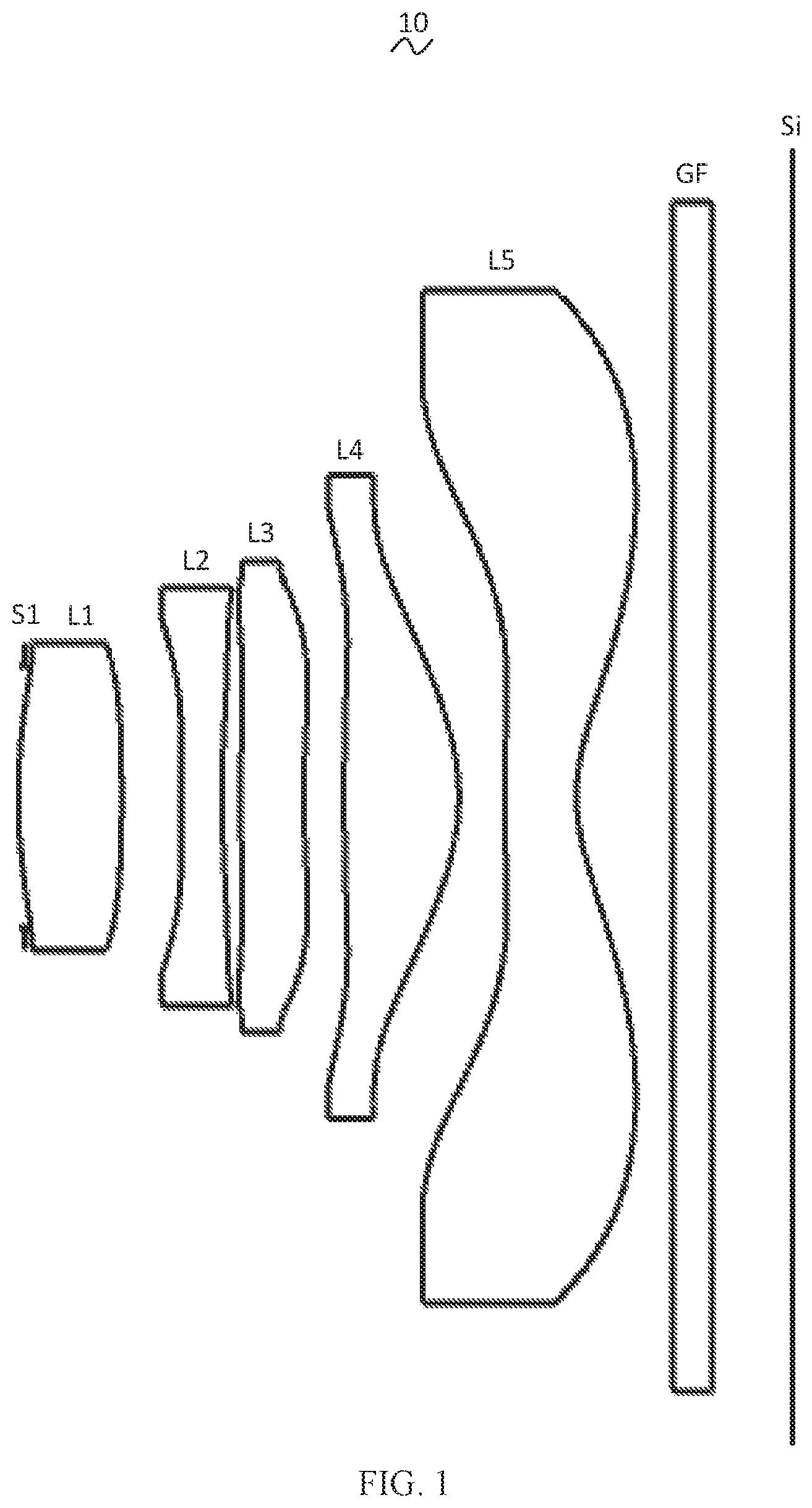
Referring to the drawings, the present disclosure provides a camera optical lens 10 . is a schematic diagram of a structure of a camera optical lens 10 according to Embodiment 1 of the present disclosure. The camera optical lens 10 includes five lenses. Specifically, a left side is an object side, a right side is an image side, the camera optical lens 10 includes, from the object side to the image side: an aperture S 1 , a first lens L 1 , a second lens L 2 , a third lens L 3 , a fourth lens L 4 and a fifth lens L 5 . An optical element such as an optical filter (GF) can be arranged between the fifth lens L 5 and an image surface Si.
In the embodiment, the first lens L 1 , the second lens L 2 , the third lens L 3 , the fourth lens L 4 and the fifth lens L 5 are all made of plastic material. In other embodiments, each lens may also be made of other materials.
In the embodiment, a focal length of the camera optical lens 10 is defined as f, a focal length of the first lens L 1 is defined as f1, and the camera optical lens 10 satisfies a condition of 0.95≤f1/f≤1.30, which specifies a ratio of the focal length f1 of the first lens L 1 to the focal length f of the camera optical lens 10 . Within this range, a spherical aberration and a field curvature of the camera optical lens 10 can be effectively balanced.
An on-axis distance from an image-side surface of the first lens L 1 to an object-side surface of the second lens L 2 is defined as d2, an on-axis distance from an image-side surface of the second lens L 2 to an object-side surface of the third lens L 3 is defined as d4, and the camera optical lens 10 further satisfies a condition of 2.40≤d2/d4≤5.00, which specifies a ratio of the on-axis distance d2 from the image-side surface of the first lens L 1 to the object-side surface of the second lens L 2 to the on-axis distance d4 from the image-side surface of the second lens L 2 to the object-side surface of the third lens L 3 . Within this range, it is beneficial for reducing a total optical length and thereby realizing an ultra-thin effect.
A curvature radius of the object-side surface of the third lens L 3 is defined as R5, a curvature radius of an image-side surface of the third lens L 3 is defined as R6, and the camera optical lens 10 further satisfies a condition of 3.00≤(R5+R6)/(R5−R6)≤8.00, which specifies a shape of the third lens L 3 . Within this range, a degree of deflection of the light passing through the lens can be alleviated, and aberrations can be reduced effectively.
An curvature radius of an object-side surface of the fifth lens L 5 is defined as R9, a curvature radius of an image-side surface of the fifth lens L 5 is defined as R10, and the camera optical lens 10 further satisfies a condition of 1.00≤(R9+R10)/(R9−R10)≤3.00, which specifies a shape of the fifth lens L 5 . Within this range, it can facilitate correction of an off-axis aberration.
In the embodiment, the first lens L 1 has a positive refractive power, an object-side surface of the first lens L 1 is convex in a paraxial region, and the image-side surface of the first lens L 1 is convex in the paraxial region. In other embodiments, the object-side surface and the image-side surface of the first lens L 1 may also be set to other concave or convex distribution situations.
A curvature radius of the object-side surface of the first lens L 1 is defined as R1, a curvature radius of the image-side surface of the first lens L 1 is defined as R2, and the camera optical lens 10 further satisfies a condition of −1.25≤(R1+R2)/(R1−R2)≤−0.10. By reasonably controlling a shape of the first lens L 1 , so that the first lens L 1 can effectively correct a spherical aberration of the camera optical lens 10 . The camera optical lens 10 further satisfies a condition of −0.78≤(R1+R2)/(R1−R2)≤−0.13.
An on-axis thickness of the first lens L 1 is defined as d1, a total optical length from the object-side surface of the first lens L 1 to an image surface of the camera optical lens 10 along an optical axis is defined as TTL, and the camera optical lens 10 satisfies a condition of 0.05≤d1/TTL≤0.22. Within this range, it is beneficial for achieving ultra-thin. The camera optical lens 10 further satisfies a condition of 0.08≤d1/TTL≤0.17.
In the embodiment, the second lens L 2 has a negative refractive power, the object-side surface of the second lens L 2 is concave in the paraxial region, and the image-side surface of the second lens L 2 is concave in the paraxial region. In other embodiments, the second lens L 2 may also have a positive refractive power, the object-side surface and the image-side surface of the second lens L 2 may also be set to other concave or convex distribution situations.
In the embodiment, a focal length of the second lens L 2 is defined as f2, and the camera optical lens 10 satisfies a condition of −3.92≤f2/f≤−1.00. By controlling the negative refractive power of the second lens L 2 within a reasonable range, it is beneficial for correcting an aberration of the camera optical lens 10 . The camera optical lens 10 further satisfies a condition of −2.45≤f2/f≤−1.25.
A curvature radius of the object-side surface of the second lens L 2 is defined as R3, a curvature radius of the image-side surface of the second lens L 2 is defined as R4, and the camera optical lens 10 further satisfies a condition of −0.15≤(R3+R4)/(R3−R4)≤1.37, which specifies a shape of the second lens L 2 . Within this range, a development towards ultra-thin lenses would facilitate correcting a problem of an on-axis aberration. The camera optical lens 10 further satisfies a condition of −0.10≤(R3+R4)/(R3−R4)≤1.10.
An on-axis thickness of the second lens L 2 is defined as d3, and the camera optical lens 10 further satisfies a condition of 0.03≤d3/TTL≤0.10. Within this range, it is beneficial for achieving ultra-thin. The camera optical lens 10 further satisfies a condition of 0.04≤d3/TTL≤0.08.
In the embodiment, the third lens L 3 has a negative refractive power, the object-side surface of the third lens L 3 is convex in the paraxial region, and an image-side surface of the third lens L 3 is concave in the paraxial region. In other embodiments, the third lens L 3 may also have a positive refractive power, the object-side surface and the image-side surface of the third lens L 3 may also be set to other concave or convex distribution situations.
A focal length of the third lens L 3 is defined as f3, and the camera optical lens 10 further satisfies a condition of −20.72≤f3/f≤−2.89, The appropriate distribution of the refractive power leads to a better imaging quality and a lower sensitivity of the system. The camera optical lens 10 further satisfies a condition of −12.95≤f3/f≤−3.61.
An on-axis thickness of the third lens L 3 is defined as d5, and the camera optical lens 10 further satisfies a condition of 0.04≤d5/TTL≤0.13. Within this range, it is beneficial for achieving ultra-thin. The camera optical lens 10 further satisfies a condition of 0.07≤d5/TTL≤0.11.
In the embodiment, the fourth lens L 4 has a positive refractive power, an object-side surface of the fourth lens L 4 is convex in the paraxial region, and an image-side surface of the fourth lens L 4 is convex in the paraxial region. In other embodiments, the fourth lens L 4 may also have a negative refractive power, the object-side surface and the image-side surface of the fourth lens L 4 may also be set to other concave or convex distribution situations.
A focal length of the fourth lens L 4 is defined as f4, and the camera optical lens 10 further satisfies a condition of 0.25≤f4/f≤0.90, which specifies a ratio of the focal length f4 of the fourth lens L 4 to the focal length f of the camera optical lens 10 . By a reasonable distribution of the focal length, the camera optical lens has an excellent imaging quality and a lower sensitivity. The camera optical lens 10 further satisfies a condition of 0.40≤f4/f≤0.72.
A curvature radius of an object-side surface of the fourth lens L 4 is defined as R7, a curvature radius of an image-side surface of the fourth lens L 4 is defined as R8, and the camera optical lens 10 further satisfies a condition of 0.46≤(R7+R8)/(R7−R8)≤1.53, which specifies a shape of the fourth lens L 4 . Within this range, a development towards ultra-thin and a wide-angle lens would facilitate correcting a problem of an off-axis aberration. The camera optical lens 10 further satisfies a condition of 0.73≤(R7+R8)/(R7−R8)≤1.22.
An on-axis thickness of the fourth lens L 4 is d7, and the camera optical lens 10 further satisfies a condition of 0.06≤d7/TTL≤0.26. Within this range, it is beneficial for achieving ultra-thin. The camera optical lens 10 further satisfies a condition of 0.09≤d7/TTL≤0.21.
In the embodiment, the fifth lens L 5 has a negative refractive power, the object-side surface of the fifth lens L 5 is convex in the paraxial region, and the image-side surface of the fifth lens L 5 is concave in the paraxial region. In other embodiments, the fifth lens L 5 may also have a positive refractive power, the object-side surface and the image-side surface of the fifth lens L 5 may also be set to other concave or convex distribution situations.
A focal length of the fifth lens L 5 is defined as f5, and the camera optical lens 10 further satisfies a condition of −2.01≤f5/f≤−0.33. By defining the fifth lens L 5 , a light angle of the imaging optical lens can be smoothed effectively and a tolerance sensitivity can be reduced. The camera optical lens 10 further satisfies a condition of −1.25≤f5/f≤−0.42.
An on-axis thickness of the fifth lens L 5 is defined as d9, and the camera optical lens 10 further satisfies a condition of 0.05≤d9/TTL≤0.16. Within this range, it is beneficial for achieving ultra-thin. The camera optical lens 10 further satisfies a condition of 0.07≤d9/TTL≤0.13.
A combined focal length of the first lens L 1 and the second lens L 2 is defined as f12, and the camera optical lens 10 further satisfies a condition of 0.86≤f12/f≤6.68. Within this range, an aberration and a distortion of the camera optical lens 10 can be eliminated, and a back focal length of the camera optical lens 10 can be suppressed to maintain a miniaturization of an imaging lens system group. The camera optical lens 10 further satisfies a condition of 1.38≤f12/f≤5.35.
An F number of the camera optical lens 10 is defined as FNO. The camera optical lens 10 should satisfy a condition of FNO≤2.50. When the condition is satisfied, the camera optical lens 10 could have a large aperture. The camera optical lens 10 further satisfies a condition of FNO≤2.45.
A field of view of the camera optical lens 10 in a diagonal direction is defined as FOV, and the camera optical lens 10 satisfies the following condition: FOV≥89.00°, which specifies a range of the field of view of the camera optical lens 10 in a diagonal direction, so that the camera optical lens 10 has a wide-angle.
In the embodiment, an image height of the camera optical lens 10 is defined as IH, and the camera optical lens 10 further satisfies a condition of TTL/IH≤1.40, which is beneficial for achieving ultra-thin.
When satisfying above conditions, the camera optical lens 10 has excellent optical performances, and meanwhile can meet design requirements of a wide-angle and ultra-thin. According the characteristics of the camera optical lens 10 , it is particularly suitable for a mobile camera lens component and a WEB camera lens composed of high pixel CCD, CMOS.
In the following, embodiments will be used to describe the camera optical lens 10 of the present disclosure. The symbols recorded in each embodiment will be described as follows. The focal length, on-axis distance, curvature radius, on-axis thickness, inflexion point position, and arrest point position are all in units of mm.
TTL: Optical length (the total optical length from the object-side surface of the first lens L 1 to the image surface Si of the camera optical lens along the optical axis) in mm.
The F number (FNO) means a ratio of an effective focal length of the camera optical lens to an entrance pupil diameter (ENPD).
In addition, inflexion points and/or arrest points can be arranged on the object-side surface and the image-side surface of the lens, so as to satisfy the demand for high quality imaging. The description below can be referred for specific implementations.
Table 1 and Table 2 show design data of the camera optical lens 10 shown in .
TABLE 1
R d nd vd
S1 ∞ d0= −0.036
R1 2.251 d1= 0.539 nd1 1.5444 v1 55.82
R2 −9.793 d2= 0.316
R3 −86.255 d3= 0.210 nd2 1.6610 v2 20.53
R4 3.926 d4= 0.098
R5 4.974 d5= 0.331 nd3 1.5661 v3 37.71
R6 3.317 d6= 0.211
R7 19.175 d7= 0.600 nd4 1.5444 v4 55.82
R8 −0.843 d8= 0.236
R9 4.275 d9= 0.380 nd5 1.5438 v5 56.03
R10 0.722 d10= 0.500
R11 ∞ d11= 0.210 ndg 1.5168 vg 64.17
R12 ∞ d12= 0.423
Herein, meanings of various symbols will be described as follows.
•
• SL: aperture. • R: curvature radius of an optical surface. • R1: curvature radius of the object-side surface of the first lens L 1 . • R2: curvature radius of the image-side surface of the first lens L 1 . • R3: curvature radius of the object-side surface of the second lens L 2 . • R4: curvature radius of the image-side surface of the second lens L 2 . • R5: curvature radius of the object-side surface of the third lens L 3 . • R6: curvature radius of the image-side surface of the third lens L 3 . • R7: curvature radius of the object-side surface of the fourth lens L 4 . • R8: curvature radius of the image-side surface of the fourth lens L 4 . • R9: curvature radius of the object-side surface of the fifth lens L 5 . • R10: curvature radius of the image-side surface of the fifth lens L 5 . • R11: curvature radius of an object-side surface of the optical filter (GF). • R12: curvature radius of an image-side surface of the optical filter (GF). • d: on-axis thickness of a lens and an on-axis distance between lens. • d0: on-axis distance from the aperture S 1 to the object-side surface of the first lens L 1 . • d1: on-axis thickness of the first lens L 1 . • d2: on-axis distance from the image-side surface of the first lens L 1 to the object-side surface of the second lens L 2 . • d3: on-axis thickness of the second lens L 2 . • d4: on-axis distance from the image-side surface of the second lens L 2 to the object-side surface of the third lens L 3 . • d5: on-axis thickness of the third lens L 3 . • d6: on-axis distance from the image-side surface of the third lens L 3 to the object-side surface of the fourth lens L 4 . • d7: on-axis thickness of the fourth lens L 4 . • d8: on-axis distance from the image-side surface of the fourth lens L 4 to the object-side surface of the fifth lens L 5 . • d9: on-axis thickness of the fifth lens L 5 . • d10: on-axis distance from the image-side surface of the fifth lens L 5 to the object-side surface of the optical filter (GF). • d11: on-axis thickness of the optical filter (GF). • d12: on-axis distance from the image-side surface of the optical filter (GF) to the image surface Si. • nd: refractive index of a d line (when the d line is green light with a wavelength of 550 nm). • nd1: refractive index of the d line of the first lens L 1 . • nd2: refractive index of the d line of the second lens L 2 . • nd3: refractive index of the d line of the third lens L 3 . • nd4: refractive index of the d line of the fourth lens L 4 . • nd5: refractive index of the d line of the fifth lens L 5 . • ndg: refractive index of the d line of the optical filter (GF). • vd: abbe number. • v1: abbe number of the first lens L 1 . • v2: abbe number of the second lens L 2 . • v3: abbe number of the third lens L 3 . • v4: abbe number of the fourth lens L 4 . • v5: abbe number of the fifth lens L 5 . • vg: abbe number of the optical filter (GF).
Table 2 shows aspherical surface data of each lens of the camera optical lens 10 in Embodiment 1 of the present disclosure.
TABLE 2
Conic coefficient Aspheric surface coefficients
k A4 A6 A8 A10 A12
R1 −3.9972E+00 −4.3116E−02 −2.0386E−01 9.3750E+00 −1.4298E+02 1.0484E+03
R2 1.7115E+02 −4.3602E−02 −4.0556E+00 5.6427E+01 −4.5062E+02 2.1645E+03
R3 4.9647E+03 −2.3654E−01 −6.0426E−01 −1.1139E+00 3.5530E+01 −2.0606E+02
R4 −4.0218E+01 −8.1485E−02 −4.3225E−01 1.9611E+00 −1.9571E+00 −7.4294E+00
R5 −3.2979E+02 −7.6812E−03 −9.1999E−01 2.1526E+00 2.3652E+00 −1.8406E+01
R6 −3.4940E+01 −1.3877E−01 −5.6865E−01 1.3583E+00 −1.1759E+00 −2.1146E+00
R7 1.1724E+02 1.4218E−01 −4.8325E−01 8.7468E−01 −1.6878E+00 2.4735E+00
R8 −7.2481E−01 5.9916E−01 −1.0226E+00 2.0769E+00 −3.1335E+00 3.1731E+00
R9 −8.8869E−01 −2.4357E−01 −4.8033E−02 1.9811E−01 −1.5366E−01 6.4158E−02
R10 −4.0290E+00 −1.9610E−01 1.3647E−01 −7.3401E−02 3.0134E−02 −9.4147E−03
Conic coefficient Aspheric surface coefficients
k A14 A16 A18 A20
R1 −3.9972E+00 −4.3068E+03 1.0082E+04 −1.2523E+04 6.3682E+03
R2 1.7115E+02 −6.3719E+03 1.1250E+04 −1.0924E+04 4.4837E+03
R3 4.9647E+03 6.0354E+02 −9.7341E+02 8.2520E+02 −2.8830E+02
R4 −4.0218E+01 2.7244E+01 −3.7731E+01 2.5044E+01 −6.6584E+00
R5 −3.2979E+02 3.3852E+01 −3.0073E+01 1.3516E+01 −2.5139E+00
R6 −3.4940E+01 7.8688E+00 −1.0354E+01 6.4721E+00 −1.5641E+00
R7 1.1724E+02 −2.3211E+00 1.3215E+00 −4.1571E−01 5.5251E−02
R8 −7.2481E−01 −2.0175E+00 7.7073E−01 −1.6208E−01 1.4487E−02
R9 −8.8869E−01 −1.5692E−02 2.2358E−03 −1.7846E−04 6.9235E−06
R10 −4.0290E+00 2.1265E−03 −3.2126E−04 2.8555E−05 −1.1139E−06
For convenience, an aspheric surface of each lens surface uses the aspheric surfaces shown in the above condition (1). However, the present disclosure is not limited to the aspherical polynomials form shown in the condition (1). z =( cr 2 )/{1+[1−( k+ 1)( c 2 r 2 )] 2 }+A 4 r 4 +A 6 r 6 +A 8 r 8 +A 10 r 10 +A 12 r 12 +A 14 r 14 +A 16 r 16 +A 18 r 18 +A 20 r 20 (1)
Herein, k is a conic coefficient, and A4, A6, A8, A10, A12, A14, A16, A18 and A20 are aspherical surface coefficients, c is a curvature of the optical surface, r is a vertical distance between a point on an aspherical curve and the optic axis, and z is an aspherical depth (a vertical distance between a point on an aspherical surface, having a distance of r from the optic axis, and a surface tangent to a vertex of the aspherical surface on the optic axis).
Table 3 and Table 4 show design data of inflexion points and arrest points of the camera optical lens 10 according to Embodiment 1 of the present disclosure. Herein P1R1 and P1R2 represent the object-side surface and the image-side surface of the first lens L 1 , P2R1 and P2R2 represent the object-side surface and the image-side surface of the second lens L 2 , P3R1 and P3R2 represent the object-side surface and the image-side surface of the third lens L 3 , P4R1 and P4R2 represent the object-side surface and the image-side surface of the fourth lens L 4 , P5R1 and P5R2 represent the object-side surface and the image-side surface of the fifth lens L 5 . The data in the column named “inflexion point position” refer to vertical distances from inflexion points arranged on each lens surface to the optical axis of the camera optical lens 10 . The data in the column named “arrest point position” refer to vertical distances from arrest points arranged on each lens surface to the optical axis of the camera optical lens 10 .
TABLE 3
Number of Inflexion point Inflexion point Inflexion point
inflexion points position 1 position 2 position 3
P1R1 1 0.515 / /
P1R2 0 / / /
P2R1 2 0.745 0.775 /
P2R2 3 0.355 0.675 0.915
P3R1 2 0.255 0.785 /
P3R2 2 0.295 0.945 /
P4R1 2 0.495 1.265 /
P4R2 3 0.815 1.405 1.465
P5R1 2 0.285 1.325 /
P5R2 1 0.495 / /
TABLE 4
Number of Arrest point Arrest point
arrest points position 1 position 2
P1R1 0 / /
P1R2 0 / /
P2R1 0 / /
P2R2 0 / /
P3R1 2 0.465 0.885
P3R2 2 0.495 1.045
P4R1 1 0.695 /
P4R2 0 / /
P5R1 1 0.495 /
P5R2 1 1.355 /
and illustrate a longitudinal aberration and a lateral color with wavelengths of 650 nm, 610 nm, 555 nm, 510 nm, and 470 nm after passing the camera optical lens 10 according to Embodiment 1, respectively. illustrates a field curvature and a distortion with a wavelength of 555 nm after passing the camera optical lens 10 according to Embodiment 1. A field curvature S in is a field curvature in a sagittal direction, and T is a field curvature in a tangential direction.
Table 13 in the following shows various values of Embodiments 1, 2, and 3, and also values corresponding to parameters which are specified in the above conditions.
As shown in Table 13, Embodiment 1 satisfies the above conditions.
In the embodiment, an entrance pupil diameter (ENPD) of the camera optical lens 10 is 1.182 mm, an image height IH of 1.0H is 2.920 mm, an FOV is 89.800. Thus, the camera optical lens 10 can meet the design requirements of a wide-angle and ultra-thin, and its on-axis and off-axis chromatic aberrations are fully corrected, thereby achieving excellent optical characteristics.
Embodiment 2
is a schematic diagram of a structure of a camera optical lens 20 according to Embodiment 2 of the present disclosure. Embodiment 2 is basically the same as Embodiment 1 and involves symbols having the same meanings as Embodiment 1, and only differences therebetween will be described in the following.
In the embodiment, an object-side surface of a fourth lens L 4 is concave in a paraxial region.
Table 5 and Table 6 show design data of a camera optical lens 20 in Embodiment 2 of the present disclosure.
TABLE 5
R d nd vd
S1 ∞ d0= 0.002
R1 2.698 d1= 0.408 nd1 1.5444 v1 55.82
R2 −6.934 d2= 0.345
R3 −14.069 d3= 0.262 nd2 1.6610 v2 20.53
R4 3.479 d4= 0.069
R5 4.010 d5= 0.355 nd3 1.5661 v3 37.71
R6 3.118 d6= 0.226
R7 −93.335 d7= 0.467 nd4 1.5444 v4 55.82
R8 −0.909 d8= 0.049
R9 1.155 d9= 0.399 nd5 1.5438 v5 56.03
R10 0.577 d10= 0.666
R11 ∞ d11= 0.210 ndg 1.5168 vg 64.17
R12 ∞ d12= 0.598
Table 6 shows aspherical surface data of each lens of the camera optical lens 20 in Embodiment 2 of the present disclosure.
TABLE 6
Conic coefficient Aspheric surface coefficients
k A4 A6 A8 A10 A12
R1 −9.0884E+00 −6.5326E−02 −3.3159E−01 1.0052E+01 −1.4559E+02 1.0485E+03
R2 7.1724E+01 −7.0051E−02 −3.9652E+00 5.6231E+01 −4.5136E+02 2.1654E+03
R3 8.6299E+01 −2.0308E−01 −5.6933E−01 −1.2947E+00 3.5633E+01 −2.0574E+02
R4 −4.0556E+01 −7.5693E−02 −3.8842E−01 1.9460E+00 −2.0819E+00 −7.4746E+00
R5 −3.9535E+02 9.1255E−03 −8.4735E−01 2.1240E+00 2.3415E+00 −1.8415E+01
R6 −1.4467E+02 −1.2082E−01 −5.8182E−01 1.3635E+00 −1.1653E+00 −2.1119E+00
R7 −1.0001E+03 1.8443E−01 −4.9001E−01 8.6956E−01 −1.6863E+00 2.4754E+00
R8 −7.2927E−01 5.8849E−01 −1.0236E+00 2.0775E+00 −3.1335E+00 3.1728E+00
R9 −3.3510E+00 −2.5013E−01 −4.9062E−02 1.9800E−01 −1.5364E−01 6.4164E−02
R10 −3.0466E+00 −2.1125E−01 1.3870E−01 −7.3540E−02 3.0131E−02 −9.4148E−03
Conic coefficient Aspheric surface coefficients
k A14 A16 A18 A20
R1 −9.0884E+00 −4.2899E+03 1.0083E+04 −1.2681E+04 6.6131E+03
R2 7.1724E+01 −6.3669E+03 1.1248E+04 −1.0955E+04 4.5195E+03
R3 8.6299E+01 6.0354E+02 −9.7412E+02 8.2391E+02 −2.8636E+02
R4 −4.0556E+01 2.7342E+01 −3.7657E+01 2.5001E+01 −6.7178E+00
R5 −3.9535E+02 3.3844E+01 −3.0093E+01 1.3508E+01 −2.5050E+00
R6 −1.4467E+02 7.8695E+00 −1.0353E+01 6.4720E+00 −1.5715E+00
R7 −1.0001E+03 −2.3207E+00 1.3211E+00 −4.1611E−01 5.5326E−02
R8 −7.2927E−01 −2.0178E+00 7.7060E−01 −1.6212E−01 1.4510E−02
R9 −3.3510E+00 −1.5689E−02 2.2365E−03 −1.7829E−04 6.8355E−06
R10 −3.0466E+00 2.1263E−03 −3.2132E−04 2.8552E−05 −1.1109E−06
Table 7 and table 8 show design data of inflexion points and arrest points of each lens of the camera optical lens 20 lens according to Embodiment 2 of the present disclosure.
TABLE 7
Number of Inflexion point Inflexion point Inflexion point
inflexion points position 1 position 2 position 3
P1R1 1 0.425 / /
P1R2 0 / / /
P2R1 0 / / /
P2R2 1 0.395 / /
P3R1 3 0.255 0.795 0.925
P3R2 2 0.245 0.935 /
P4R1 2 0.075 0.525 /
P4R2 2 0.745 1.335 /
P5R1 2 0.445 1.415 /
P5R2 1 0.505 / /
TABLE 8
Number of Arrest point Arrest point
arrest points position 1 position 2
P1R1 0 / /
P1R2 0 / /
P2R1 0 / /
P2R2 1 0.845 /
P3R1 2 0.615 0.865
P3R2 1 0.435 /
P4R1 2 0.125 0.705
P4R2 1 1.215 /
P5R1 1 0.855 /
P5R2 1 1.375 /
and illustrate a longitudinal aberration and a lateral color with wavelengths of 650 nm, 610 nm, 555 nm, 510 nm, and 470 nm after passing the camera optical lens 20 according to Embodiment 2, respectively. illustrates a field curvature and a distortion with a wavelength of 555 nm after passing the camera optical lens 20 according to Embodiment 2. A field curvature S in is a field curvature in a sagittal direction, and T is a field curvature in a tangential direction.
As shown in Table 13, Embodiment 2 satisfies the above conditions.
In the embodiment, an entrance pupil diameter (ENPD) of the camera optical lens 20 is 1.145 mm, an image height IH of 1.0H is 2.920 mm, an FOV is 91.80°. Thus, the camera optical lens 20 can meet the design requirements of a large aperture, a wide-angle and ultra-thin, and its on-axis and off-axis chromatic aberrations are fully corrected, thereby achieving excellent optical characteristics.
Embodiment 3
is a schematic diagram of a structure of a camera optical lens 30 according to Embodiment 3 of the present disclosure. Embodiment 3 is basically the same as Embodiment 1 and involves symbols having the same meanings as Embodiment 1, and only differences therebetween will be described in the following.
Table 9 and Table 10 show design data of a camera optical lens 30 in Embodiment 3 of the present disclosure.
TABLE 9
R d nd vd
S1 ∞ d0= −0.005
R1 2.502 d1= 0.587 nd1 1.5444 v1 55.82
R2 −3.425 d2= 0.262
R3 −6.145 d3= 0.218 nd2 1.6610 v2 20.53
R4 7.156 d4= 0.109
R5 6.823 d5= 0.333 nd3 1.5661 v3 37.71
R6 3.415 d6= 0.185
R7 24.346 d7= 0.699 nd4 1.5444 v4 55.82
R8 −0.810 d8= 0.210
R9 79.874 d9= 0.441 nd5 1.5438 v5 56.03
R10 0.773 d10= 0.451
R11 ∞ d11= 0.210 ndg 1.5168 vg 64.17
R12 ∞ d12= 0.355
Table 10 shows aspherical surface data of each lens of the camera optical lens 30 in Embodiment 3 of the present disclosure.
TABLE 10
Conic coefficient Aspherical surface coefficients
k A4 A6 A8 A10 A12
R1 −4.6524E+00 −6.6270E−02 −2.2112E−01 8.7054E+00 −1.4215E+02 1.0533E+03
R2 1.7887E+01 −4.8500E−02 −4.1283E+00 5.6870E+01 −4.5078E+02 2.1640E+03
R3 −4.1958E+01 −2.2515E−01 −4.7604E−01 −9.6641E−01 3.5716E+01 −2.0626E+02
R4 −2.6648E−01 −6.1769E−02 −3.8744E−01 1.9960E+00 −1.9685E+00 −7.4754E+00
R5 −5.4711E+02 −1.9794E−02 −9.1594E−01 2.1586E+00 2.3738E+00 −1.8387E+01
R6 −2.6219E+01 −1.2467E−01 −5.6266E−01 1.3531E+00 −1.1774E+00 −2.1161E+00
R7 1.0629E+02 1.2912E−01 −4.9281E−01 8.7246E−01 −1.6922E+00 2.4697E+00
R8 −7.2421E−01 5.8455E−01 −1.0265E+00 2.0761E+00 −3.1337E+00 3.1732E+00
R9 9.9989E+02 −2.3560E−01 −4.6142E−02 1.9858E−01 −1.5357E−01 6.4168E−02
R10 −4.7513E+00 −1.9097E−01 1.3553E−01 −7.3408E−02 3.0141E−02 −9.4141E−03
Conic coefficient Aspherical surface coefficients
k A14 A16 A18 A20
R1 −4.6524E+00 −4.3065E+03 1.0053E+04 −1.2596E+04 6.5835E+03
R2 1.7887E+01 −6.3709E+03 1.1250E+04 −1.0927E+04 4.4862E+03
R3 −4.1958E+01 6.0286E+02 −9.7402E+02 8.2550E+02 −2.8641E+02
R4 −2.6648E−01 2.7200E+01 −3.7737E+01 2.5105E+01 −6.6294E+00
R5 −5.4711E+02 3.3877E+01 −3.0059E+01 1.3521E+01 −2.5623E+00
R6 −2.6219E+01 7.8716E+00 −1.0351E+01 6.4757E+00 −1.5652E+00
R7 1.0629E+02 −2.3233E+00 1.3208E+00 −4.1588E−01 5.5381E−02
R8 −7.2421E−01 −2.0175E+00 7.7075E−01 −1.6205E−01 1.4507E−02
R9 9.9989E+02 −1.5692E−02 2.2350E−03 −1.7910E−04 6.6265E−06
R10 −4.7513E+00 2.1264E−03 −3.2130E−04 2.8556E−05 −1.1124E−06
Table 11 and Table 12 show design data inflexion points and arrest points of the respective lenses in the camera optical lens 30 according to Embodiment 3 of the present disclosure.
TABLE 11
Number of Inflexion point Inflexion point
inflexion points position 1 position 2
P1R1 1 0.445 /
P1R2 0 / /
P2R1 1 0.635 /
P2R2 0 / /
P3R1 2 0.235 0.735
P3R2 2 0.305 0.925
P4R1 1 0.445 /
P4R2 2 0.945 1.265
P5R1 2 0.075 1.265
P5R2 1 0.475 /
TABLE 12
Number of Arrest point Arrest point
arrest points position 1 position 2
P1R1 0 / /
P1R2 0 / /
P2R1 0 / /
P2R2 0 / /
P3R1 2 0.405 0.845
P3R2 1 0.515 /
P4R1 1 0.615 /
P4R2 0 / /
P5R1 1 0.115 /
P5R2 1 1.305 /
and illustrate a longitudinal aberration and a lateral color of light with wavelengths of 650 nm, 610 nm, 555 nm, 510 nm, and 470 nm after passing the camera optical lens 30 according to Embodiment 3. illustrates a field curvature and a distortion of light with a wavelength of 555 nm after passing the camera optical lens 30 according to Embodiment 3. A field curvature S in is a field curvature in a sagittal direction, and T is a field curvature in a tangential direction.
Table 13 in the following shows various values of Embodiment 3, and also values corresponding to parameters which are specified in the above conditions. Obviously, the camera optical lens 30 satisfies above conditions.
In the embodiment, an entrance pupil diameter (ENPD) of the camera optical lens 30 is 1.182 mm, an image height IH of 1.0H is 2.920 mm, an FOV is 89.80. The camera optical lens 30 can meet the design requirements of a wide-angle and ultra-thin, and its on-axis and off-axis chromatic aberrations are fully corrected, thereby achieving excellent optical characteristics.
TABLE 13
Parameters and
conditions Embodiment 1 Embodiment 2 Embodiment 3
f1/f 1.19 1.30 0.96
d2/d4 3.22 5.00 2.40
f 2.873 2.782 2.872
f1 3.405 3.610 2.743
f2 −5.627 −4.158 −4.926
f3 −18.869 −28.815 −12.458
f4 1.494 1.677 1.449
f5 −1.655 −2.791 −1.434
f12 6.505 12.396 4.943
FNO 2.43 2.43 2.43
TTL 4.054 4.054 4.060
IH 2.920 2.920 2.920
FOV 89.80° 91.80° 89.80°
The above is only illustrates some embodiments of the present disclosure, in practice, one having ordinary skill in the art can make various modifications to these embodiments in forms and details without departing from the scope of the present disclosure.
Figures (9)
Citations
This patent cites (7)
- US20120087020
- US20130002931
- US20130010374
- US20130021680
- US20160116716
- US20180239114
- US20180341086