Enhanced Microelectromechanical System Mirror Apparatus
Abstract
According to an example aspect of the present invention, there is provided a Microelectrical System, MEMS, mirror apparatus, comprising a MEMS mirror, at least two pairs of actuation units, wherein each pair comprises a first and a second actuation unit and a first actuation unit of a first pair of actuation units comprises a stress relief unit, an inner actuator and an outer actuator, and the stress relief unit is coupled to the MEMS mirror and to the inner actuator, one end of the inner actuator is coupled to the stress relief unit of the actuation unit and another end of the inner actuator is coupled to the outer actuator of the actuation unit, the stress relief unit of the first actuation unit of the first pair of actuation units is in between the MEMS mirror and an inner actuator of a second actuation unit of a second pair of actuation units, and the inner actuator of the first actuation unit of the first pair of actuation units is in between a stress relief unit of a second actuation unit of the first pair of actuation units and an outer actuator of a second actuation unit of a second pair of actuation units.
Claims (15)
1 . A Microelectrical System, MEMS, mirror apparatus, comprising: a MEMS mirror; at least two pairs of actuation units, wherein each pair comprises a first and a second actuation unit and a first actuation unit of a first pair of actuation units comprises a stress relief unit, an inner actuator and an outer actuator, and the stress relief unit is coupled to the MEMS mirror and to the inner actuator, one end of the inner actuator is coupled to the stress relief unit of the actuation unit and another end of the inner actuator is coupled to the outer actuator of the actuation unit, the stress relief unit of the first actuation unit of the first pair of actuation units is in between the MEMS mirror and an inner actuator of a second actuation unit of a second pair of actuation units, and the inner actuator of the first actuation unit of the first pair of actuation units is in between a stress relief unit of a second actuation unit of the first pair of actuation units and an outer actuator of a second actuation unit of a second pair of actuation units.
6 . A Microelectrical System, MEMS, mirror apparatus, comprising: a MEMS mirror; at least two pairs of actuation units, wherein an actuation unit of a first pair comprises an inner actuator, an inner stress relief unit, an outer actuator and an outer stress relief unit, and one end of the inner actuator is coupled to or comprises the inner stress relief unit of the actuation unit and another end of the inner actuator is coupled to the outer actuator via the outer stress relief unit, the inner stress relief unit is coupled to the MEMS mirror, one end of the outer actuator is coupled to an anchor between the outer actuator and an outer actuator of an actuation unit of a second pair of actuation units and another end of the outer actuator is coupled to the outer stress relief unit.
Show 13 dependent claims
2 . The MEMS apparatus according to claim 1 , wherein the stress relief units of all the actuation units comprise meander structures.
3 . The MEMS apparatus according to claim 1 , wherein all actuation units of the at least two pairs of actuation units are identical.
4 . The MEMS apparatus according to claim 1 , wherein the first actuation unit of the first pair of actuation units is different compared to the second actuation unit of the second pair of actuation units.
5 . The MEMS apparatus according to claim 4 , wherein the stress relief unit of the first actuation unit of the first pair of actuation units and the stress relief unit of the second actuation unit of the first pair of actuation units comprise meander structures and a height of a meander line of the stress relief unit of the first actuation unit of the first pair of actuation units is smaller than a height of the stress relief unit of the second actuation unit of the first pair of actuation units.
7 . The MEMS mirror apparatus according to claim 6 , wherein the inner and the outer stress relief units are at opposite ends of the actuation unit.
8 . The MEMS mirror apparatus according to claim 6 , wherein the outer actuator of the first pair of actuation units is coupled to a frame via a common point and the outer actuator of the actuation unit of the second pair is coupled to the frame via the same common point.
9 . The MEMS mirror apparatus according to claim 6 , wherein the outer stress relief unit is towards an outer stress relief unit of another actuation unit of the first pair with a gap in between the outer stress relief unit and the outer stress relief unit of the actuator of said another actuation unit.
10 . The MEMS apparatus according to claim 6 , wherein the gap between the outer stress relief unit and the outer stress relief unit of the actuator of said another actuation unit of the first pair comprises a coupler.
11 . The MEMS mirror apparatus according to claim 6 , wherein at least one of the inner stress relief unit and/or the outer stress relief unit comprises a meander structure.
12 . The MEMS mirror apparatus according to claim 6 , wherein the inner stress relief unit and the outer stress relief units comprise meander structures with different geometrical patterns.
13 . The MEMS mirror apparatus according to claim 6 , wherein the inner stress relief unit and the outer stress relief unit comprise meander structures and a height of a meander structure of the inner stress relief unit is smaller than a height of a meander structure of the outer stress relief unit.
14 . The MEMS mirror apparatus according to claim 6 , wherein all actuation units of the at least two pairs of actuation units are identical.
15 . The MEMS mirror apparatus according to claim 6 , wherein the inner stress relief unit is at one end of the inner actuator and the outer stress relief unit is at one end of the outer actuator, and the outer stress relief unit penetrates partly to the inner actuator.
Full Description
Show full text →
FIELD Embodiments of the present invention relate in general to a Microelectromechanical System, MEMS, mirror.
BACKGROUND
Microelectromechanical System, MEMS, mirrors are miniature mirrors, which may be used for example in projectors, displays, imaging and fiber-optic communications. MEMS mirror-based scanners are advantageous compared to other types of scanners in terms of size, speed and cost. Thus, MEMS mirrors are ideal for a wide range of applications, such as Light Detection and Ranging, LiDAR, applications. In general, it is desirable to provide robust MEMS mirrors with low power consumption, wide deflection angles and high reflectivity for circular and/or Lissajous scanning.
SUMMARY OF THE INVENTION
According to some aspects, there is provided the subject-matter of the independent claims. Some embodiments are defined in the dependent claims. According to a first aspect of the present invention, there is provided a Microelectrical System, MEMS, mirror apparatus, comprising a MEMS mirror, at least two pairs of actuation units, wherein an actuation unit of a first pair comprises an inner actuator, an inner stress relief unit, an outer actuator and an outer stress relief unit, and one end of the inner actuator is coupled to or comprises the inner stress relief unit of the actuation unit and another end of the inner actuator is coupled to the outer actuator via the outer stress relief unit, the inner stress relief unit is coupled to the MEMS mirror, one end of the outer actuator is coupled to an anchor between the outer actuator and an outer actuator of an actuation unit of a second pair of actuation units and another end of the outer actuator is coupled to the outer stress relief unit. According to a second aspect of the present invention, there is provided MEMS mirror apparatus, comprising: a MEMS mirror, at least two pairs of actuation units, wherein each pair comprises a first and a second actuation unit and a first actuation unit of a first pair of actuation units comprises a stress relief unit, an inner actuator and an outer actuator, and the stress relief unit is coupled to the MEMS mirror and to the inner actuator, one end of the inner actuator is coupled to the stress relief unit of the actuation unit and another end of the inner actuator is coupled to the outer actuator of the actuation unit, the stress relief unit of the first actuation unit of the first pair of actuation units is in between the MEMS mirror and an inner actuator of a second actuation unit of a second pair of actuation units, and the inner actuator of the first actuation unit of the first pair of actuation units is in between a stress relief unit of a second actuation unit of the first pair of actuation units and an outer actuator of a second actuation unit of a second pair of actuation units.
BRIEF DESCRIPTION OF THE DRAWINGS
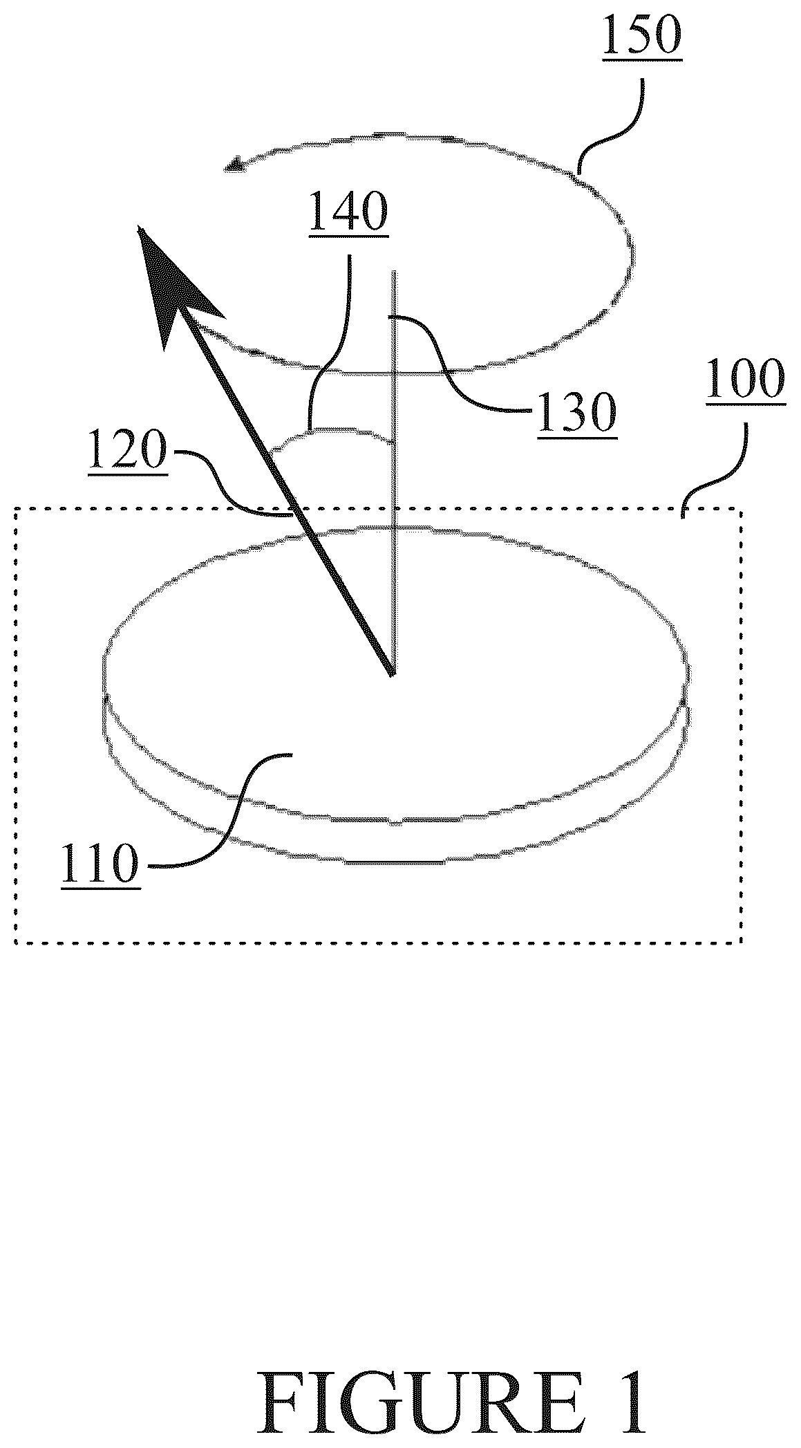
illustrates operation of a MEMS mirror in accordance with at least some embodiments of the present invention; illustrates driving of a MEMS mirror in accordance with at least some embodiments of the present invention; illustrates Lissajous scanning in accordance with at least some embodiments of the present invention; illustrates a first MEMS mirror apparatus in accordance with at least some embodiments of the present invention; illustrates a second MEMS mirror apparatus in accordance with at least some embodiments of the present invention; illustrates a third MEMS mirror apparatus in accordance with at least some embodiments of the present invention; illustrates a fourth MEMS mirror apparatus in accordance with at least some embodiments of the present invention; illustrates a third MEMS mirror apparatus in accordance with at least some embodiments of the present invention. EMBODIMENTS Embodiments of the present invention relate in general to Microelectromechanical System, MEMS, mirrors. More specifically, embodiments of the present invention allow low voltage excitation and large tilt angle for circular and/or Lissajous scanning. Stress relief units, such as lever arms, may be exploited to provide high tolerance to mechanical breakage and enhance vertical displacement of actuation units. For instance, stress relief units having a meander structure may be used to increase a moment of inertia of a vibrating structure of a MEMS mirror apparatus and to reduce a spring constant to lower a mechanical resonance frequency. In some embodiments, asymmetric design of the MEMS mirror apparatus allows optimization of resonant frequencies. Embodiments of the present invention may be exploited in various applications, such as medical imaging, environmental sensing and optical communication links. In some embodiments of the present invention, a MEMS mirror may be used to refer to a Micro-Opto-Electromechanical System, MOEMS, mirror. A MOEMS mirror may be a mirror that is used in optical applications. That is to say, a MEMS mirror may be a general term, which is not limited to any specific application, and a MEMS mirror covers for example a MOEMS mirror as well. illustrates operation of a MEMS mirror in accordance with at least some embodiments of the present invention. In , MEMS mirror apparatus is denoted by 100 . MEMS mirror, or a surface of MEMS mirror more specifically, is denoted by 110 . At least one outgoing beam is denoted by 120 , normal to the surface 110 is denoted by 130 , deflection angle is denoted by 140 and circular scan is shown by arrow 150 . Even though circular scan 150 is shown as an example in , at least some embodiments of the present invention may be used to perform Lissajous scanning additionally, or alternatively. In some embodiments of the present invention, MEMS mirror 110 may be tilted and a laser beam may be directed using MEMS mirror 110 to provide at least one outgoing beam 120 . Thus, circular scan 150 may be provided by rotating at least one outgoing beam 120 around normal 130 . MEMS mirror 110 may be tilted by deflection angle 140 as well. Normal 130 may refer to a vertical direction. The expression “vertical” may mean a direction which is identical with the normal to the surface of the Earth and the expression “horizontal” may mean a direction which is perpendicular to the normal to the surface of the Earth. In some embodiments, normal 130 may be related to MEMS mirror apparatus 100 . For instance, the expression “vertical” may mean a direction which is identical with normal 130 of MEMS mirror apparatus 100 and “horizontal” may mean a direction which is perpendicular to normal 130 of MEMS mirror apparatus 100 . illustrates driving of a MEMS mirror in accordance with at least some embodiments of the present invention. may illustrate a part of MEMS mirror apparatus 100 of for example. MEMS mirror apparatus 100 may comprise MEMS mirror 110 . Similarly as in , outgoing beam is denoted by 120 , normal is denoted by 130 and circular scan is denoted by 150 . In , examples of actuation units 205 are shown. MEMS mirror apparatus 100 may comprise at least three actuation units 205 . In general, a MEMS mirror may be a mirror, such as mirror 110 , which comprises coupling points for each actuation unit 205 such that each actuation unit 205 may control tilting of the MEMS mirror. Each actuation unit 205 may comprise actuator 210 , such as a piezo-spring, anchor 220 and coupler 230 between actuator 210 and mirror 110 . Actuator 210 may be referred to as a piezoelectric actuator as well. Actuation units 205 may be configured to cause a scanning motion for circular scan 150 , i.e., to cause the trajectory of circular scan 150 by controlling movement of MEMS mirror 110 . In some embodiments of the present invention, the scanning motion may be referred to as a wobbling mode scanning motion, e.g., if circular scan 150 is performed. For instance, wobbling mode may be exploited in Light Detection and Ranging, LiDAR, applications. Alternatively, the scanning motion may be referred to as a Lissajous mode for example if MEMS mirror 100 is tilted horizontally and vertically in an unsynchronized manner. illustrates scanning pattern of Lissajous scanning. Lissajous scanning may be either synchronized (stable) or unsynchronized (unstable). In synchronous Lissajous scanning the scanning pattern may be stable (ratio of the horizontal and vertical oscillation frequencies is n m where n and m are integers). In unsynchronous Lissajous scanning the scanning pattern may vary with time. LiDARs may use electric motor operated MEMS mirrors 110 to scan beam 120 , which may lead to large systems. Scanning mirrors may be MEMS actuators that can provide small sizes and low power consumption. MEMS scanners may use either built-in electrostatic actuation or external magnetic or galvanic actuators. Electrostatic actuation May require high driving voltages (up to hundreds of volts). Galvanic actuators may allow large scan angles, but make the system rather large. Embodiments of the present invention therefore provide low power consumption and wide deflection angles for circular and/or Lissajous scanning using a MEMS mirror apparatus. Also, high tolerance to mechanical breakage is provided to enable robust (and durable) MEMS mirrors. illustrates a first MEMS mirror apparatus in accordance with at least some embodiments of the present invention. MEMS mirror apparatus 400 of may illustrate a part of MEMS mirror apparatus 100 of for example. MEMS mirror apparatus 400 may comprise MEMS mirror 110 . Moreover, MEMS mirror apparatus 400 may comprise three actuation units. In some embodiments, MEMS mirror apparatus 400 may comprise four or more actuation units as well. A first actuation unit may comprise first actuator 410 a , first anchor 420 a and first stress relief unit 430 a , second actuation unit may comprise second actuator 410 b , second anchor 420 b and second stress relief unit 430 b and third actuation unit may comprise third actuator 410 c , third anchor 420 c and third stress relief unit 410 c . Hence, MEMS mirror apparatus 400 may be for example a 2D scanning mirror with actuators 410 a - c , such as piezoelectric actuators. MEMS mirror apparatus 400 may be arranged for example to perform circular scanning. Stress relief units 430 a - c may be, e.g., lever arms. Lever arms 430 a - c may be arranged to go along a periphery of MEMS mirror 110 but there may be gap 440 between MEMS mirror 110 and each of lever arms 430 a - c. MEMS mirror apparatus 400 may hence comprise at least three actuation units, wherein each actuation unit comprises one actuator 410 a - c , one anchor 420 a - c and one stress relief unit 430 a - c , wherein each stress relief unit 430 a - c may be coupled to MEMS mirror 110 from one end and to actuator 410 a - c from another end. That is, for example first stress relief unit 430 a may be coupled to MEMS mirror 110 from one and to first actuator 410 a from another end. Moreover, each actuator 410 a - c may be coupled to one anchor 420 a - c and one lever arm 430 a - c . That is, first actuator 410 a may be coupled to first anchor 420 a from one end and to first lever arm 430 a from another end. In some embodiments, there may be a frame (not shown in ) around, or within, MEMS mirror apparatus 100 and actuators 410 a - c may be coupled to the frame via separate anchors 420 a - c. In some embodiments, a control device may be configured to generate control signals for each actuation unit, i.e., for each actuator 410 a - c , for a resonant operation of MEMS mirror apparatus 400 . Frequencies of the control signals may be substantially equal for all actuation units, but phases of the control signals may differ. A phase shift between the control signals may be determined in order to realize circular scanning pattern and each actuator 410 a - c may be excited by an individual control/driving signal. The control signals may have the same frequency, but constant phase shift between the signals. For instance, the phase shift may be 120 degrees with three actuation units and 90 degrees with four actuation units. Excited by the control signals, actuators 410 a - c may oscillate in vertical direction. MEMS mirror 110 may be connected to all actuation units and oscillate in the wobbling mode, to provide circular reflection pattern of the normally incident laser beam 120 . Stress relief unit 430 a - c may provide high tolerance to mechanical breakage and enable large reflection angles. Stress relief units 430 a - c may be arranged to enhance vertical displacement of actuators 410 a - c and thus tilt angle of MEMS mirror 110 . Alternatively, or in addition, stress relief units 430 a - c may prevent breakage of actuators 410 a - c and allow large tilt and scanning angles of MEMS mirror 110 , e.g., up to +15 degrees mechanical tilt angle. With reference to again, MEMS mirror apparatus 400 shown in may provide circular scanning 150 of laser beam 120 with low driving voltage and large optical angle, which may be particularly beneficial in case of LiDAR applications, because circular scanning 150 can be transformed into 3D scanning by using special optical components. Another application for a circular scanner is a component of a hyperspectral light source. Actuators 410 a - c may be arranged to work in resonance to provide efficient actuation even at very low driving voltage of, e.g., about 1V. Phase shift between the control signals may be used to cause wobbling of MEMS mirror 110 and circular scanning of laser beam 140 . In the MEMS mirror apparatus of , each stress relief unit 430 a - c may connect a separate actuator 410 a - c to MEMS mirror 110 . Stress relief units 430 a - c may therefore provide mechanical amplification of vertical displacement of MEMS mirror 110 . Stress relief units 430 a - c may be narrow such that those can be placed in gap 440 between MEMS mirror 110 and actuators 410 a - c , thereby saving space. In addition, stress relief units 430 a - c may provide flexibility to act as a stress-relief unit between actuator 410 a - c and attachment points of MEMS mirror 110 . illustrates a second MEMS mirror apparatus in accordance with at least some embodiments of the present invention. may illustrate a part of MEMS mirror apparatus 100 of for example. MEMS mirror apparatus 500 may comprise MEMS mirror 110 . Moreover, MEMS mirror apparatus 500 may comprise four actuation units. A first actuation unit may comprise first inner actuator 512 a , first outer actuator 514 a , first anchor 520 a and stress relief unit 530 a . A second actuation unit may comprise second inner actuator 512 b , second outer actuator 514 b , second anchor 520 b and second stress relief unit 530 b . A third actuation unit may comprise third inner actuator 512 c , third outer actuator 514 c , third anchor 520 c and third stress relief unit 530 c . A fourth actuation unit may comprise fourth inner actuator 512 d , fourth outer actuator 514 d , fourth anchor 520 d and fourth stress relief unit 530 d. Said actuation units may work in resonance to provide efficient actuation even at very low driving voltage, e.g., of about 1V. Stress relief units 530 a - d may be used to provide high tolerance to breakage and act as lever arms, to enhance vertical displacement of the actuation units and allow large scanning angles. All actuation units and stress relief units 530 a - d may be identical. Stress relief units 530 a - d may be combined lever arm/stress relief units and have meander structures. Use of meander structures increases the moment of inertia of the vibrating structure and reduces the spring constant to lower the mechanical resonance frequency suitable for Lissajous scanning. The second MEMS mirror apparatus shown in is hence particularly beneficial in case of Lissajous scanning of laser beam 120 with low driving voltage and large optical angle, which is important at least for LiDAR applications. LiDARs may scan 2D area and Lissajous scanning is the only way to scan 2D area with high-frequency signals driving both X and Y axes, i.e., in horizontal and vertical directions. Each actuation unit may be excited by an individual control signal as in the embodiment of . Control signals for different pairs of actuation units may have different frequencies. For instance, control signals for each of outer actuators 514 a - d may be different. Moreover, control signals for actuators in a same pair may have 180 degree phase shift. That is, phase difference of control signals of first outer actuator 514 a and second outer actuator 514 b may be 180 degrees. Similarly, phase difference of control signals of third outer actuator 514 c and fourth outer actuator 514 d may be 180 degrees as well. Phase difference between control signals of first actuator 514 a and third actuator 514 may then be 90 degrees while phase difference between control signals of second actuator 514 b and fourth actuator 514 d may be 90 degrees as well. The first actuation unit and the second actuation units may thus from a first pair and the third actuation unit and the fourth actuation unit may form a second pair. When excited by the control signals, actuators 512 a - d and 514 a - d may oscillate in vertical direction. Therefore, MEMS mirror 110 may be caused to oscillate in Lissajous mode. MEMS mirror apparatus 500 may hence comprise at least two pairs of actuation units, wherein a first actuation unit of a first pair of actuation units comprises stress relief unit 530 a , inner actuator 512 a and outer actuator 514 a . Stress relief unit 530 a may be coupled to MEMS mirror 110 and to inner actuator 512 a . One end of inner actuator 512 a may be coupled to stress relief unit 530 a and another end of inner actuator 512 a may be coupled to outer actuator 514 a . Stress relief unit 530 a of the first actuation unit of the first pair of actuation units may be in between mirror 110 and inner actuator 512 d of a second actuation unit of the second pair of actuation units. Inner actuator 512 a of the first actuation unit of the first pair of actuation units may be in between stress relief unit 530 b of the second actuation unit of the first pair of actuation units and outer actuator 514 d of a second actuation unit of a second pair of actuation units. That is, MEMS mirror apparatus 500 may comprise at least two pairs of actuation units, wherein each actuation unit comprises two actuators, i.e., an inner actuator and an outer actuators, and a stress relief unit. Each stress relief unit may be coupled to mirror 110 and a separate inner actuator. Each inner actuator may be coupled to a separate outer actuator and a separate stress relief unit. Each outer actuator may be coupled to a separate inner actuator and the frame. Each pair of actuation units may comprise two identical actuation units, wherein for example point of connection 540 a of a first actuation unit of a first pair is located on imaginary line 550 passing through the geometrical centre of the MEMS mirror apparatus 500 to point of connection 540 c of a first actuation unit of a second pair, wherein points of connection 540 a and 540 c are connection points to the frame. illustrates a third MEMS mirror apparatus in accordance with at least some embodiments of the present invention. MEMS mirror apparatus 600 shown in is otherwise the same as MEMS mirror apparatus 500 of , but in case of MEMS mirror 600 actuation units may not be identical. That is, pairs of actuation units, or more specifically pairs of stress relief units, such as meander structures, may have different geometrical dimensions. Thus, actuation units can be configured to provide mechanical resonances at different frequencies optimally for Lissajous scanning. Lissajous scanning requires oscillation frequencies of X- and Y-axis to be different and asymmetry of the actuation units makes it possible to have optimal resonance frequencies for X- and Y-axis. Asymmetric actuation units enable excitation of MEMS mirror apparatus 600 at frequencies optimal for Lissajous scanning. That is, the first actuation unit of the first pair of actuation units may be different compared to the second actuation unit of the first pair of actuation units. For instance, stress relief unit 630 a of the first actuation unit of the first pair of actuation units and stress relief unit 630 b of the second actuation unit of the first pair of actuation units may be different. Stress relief unit 630 a and stress relief unit 630 b may, e.g., have a meander structure and height 640 a of a meander line of stress relief unit 630 a of the first actuation unit of the first pair of actuation units may be smaller than height 640 b of a meander line of the stress relief unit of second actuation unit 630 b of the first pair of actuation units. The meander structure makes it possible to increase the moment of inertia of the vibrating structure and reduce the spring constant to lower the mechanical resonance frequency suitable for Lissajous scanning. Hence, pairs of actuation units may have different geometrical dimensions and be arranged to provide mechanical resonances at different frequencies optimal for Lissajous scanning. That is, asymmetric design shown in allows for optimization of resonant frequencies, which is important at least for Lissajous scanning. Also in case of MEMS mirror apparatus 600 , piezoelectric actuation allows for low voltage excitation (˜1V). As in case of the example apparatus of stress relief units 630 a - d allow for large tilt angle and also act as lever arms, thereby enhancing vertical displacement of the actuation units. Therefore, MEMS mirror apparatus 600 may be particularly beneficial for long-range LiDARs. illustrates a fourth MEMS mirror apparatus in accordance with at least some embodiments of the present invention. MEMS mirror apparatus 700 shown in may be used to provide two-dimensional scanning with low driving voltage and large optical angle using laser beam 120 . Depending on application geometry of MEMS mirror apparatus 700 , MEMS mirror apparatus 700 may be tuned for either circular or Lissajous scanning. This is particularly beneficial for LiDAR applications, because scanning mirrors are key components of LiDARs. As shown in , MEMS mirror apparatus may comprise MEMS mirror 110 and at least two pairs of actuation units, wherein a first pair of actuation units may comprise actuation units 705 a and 705 b , and a second pair of actuation units may comprise actuation units 705 c and 705 d . Inner actuators are denoted by 712 a - d , inner stress relief units by 732 a - d , outer actuators by 714 a - d and outer stress relief unit by 734 a - d. Hence, MEMS mirror apparatus 700 may comprise two pairs of outer actuators, wherein the first pair comprises actuators 714 a and 714 b , and the second pair comprises actuators 714 c and 714 d . Similarly, MEMS mirror apparatus 700 may comprise two pairs of outer stress relief units, wherein the first pair comprises outer stress relief units 734 a and 734 b and the second pair comprises outer stress relief units 734 c and 734 d . MEMS mirror apparatus 700 may further comprise two pairs of inner actuators, wherein the first pair comprises inner actuators 712 a and 712 b , and the second pair comprises inner actuators 712 c and 712 d . MEMS mirror apparatus 700 may also comprise two pairs of inner stress relief units, wherein the first pair comprises inner stress relief units 732 a and 734 b , and the second pair comprises inner stress units 734 c and 734 d . All actuation units 705 a - d may be identical. Each actuation unit 705 a - d may comprise an inner actuator, an inner stress relief unit, an outer actuator and an outer stress relief unit. That is, for example first actuation unit 705 a of the first pair of actuation units may comprise inner actuator 712 a , inner stress relief unit 732 a , outer actuator 714 a and outer stress relief unit 734 a. Each pair of outer actuators may be connected to a frame via a single common point, i.e., via the same anchor. For instance, outer actuator 714 a and 714 d may be connected to the frame via common anchor point 720 ad. Each outer actuator 714 a - d may be coupled to an individual, separate outer stress relief unit 734 a - d . For instance, outer actuator 714 a of first actuation unit 705 a of the first pair of actuation units may be coupled to outer stress relief unit 734 a while outer actuator 714 b of second actuation unit 705 b of the first pair of actuation units may be coupled to outer stress relief unit 734 b . One end of outer actuator 714 a may be coupled to anchor 720 ad , wherein anchor 720 ad is between outer actuator 714 a and outer actuator 714 d of second actuation unit 705 d of the second pair of actuation units. Another end of outer actuator 714 a may be coupled to outer stress relief unit 734 a . Outer stress relief unit 734 a may be towards outer stress relief unit 734 b of second actuation unit 705 b of the first pair of actuation units. There may be gap 750 ab between outer stress relief unit 734 a and outer stress relief unit 734 b. Each inner actuator 712 a - d may be coupled to or comprise an individual, separate inner stress relief unit 732 a - d , respectively. For instance, inner actuator 712 a may comprise inner stress relief unit 732 a while inner actuator 712 b may comprise inner stress relief unit 732 b . As shown in , inner stress relief unit 732 a and inner stress relief unit 732 b may be located close to an end of inner actuator 712 a and inner actuator 712 b , respectively. Alternatively, inner stress relief unit 732 a and inner stress relief unit 732 b may be at the end of inner actuator 712 a and inner actuator 712 b , respectively. In such a case, inner actuator 712 a may be coupled to inner stress relief unit 732 a while inner actuator 712 b may be coupled to inner stress relief unit 732 b. Each inner stress relief unit may be coupled to mirror 110 . That is, inner stress relief unit 732 a may be coupled to mirror 110 and also inner stress relief unit 732 b may be coupled to mirror 110 at different places. Each inner stress relief unit 732 a - d may be at an opposite end of an actuation unit compared to a corresponding outer stress relief unit 734 a -d. Hence, inner stress relief unit 712 a may be at an opposite end of first actuation unit 705 a compared to outer stress relief unit 714 a. At least one of an inner stress relief unit 732 a - d and/or an outer stress relief unit 734 a - d of an actuation unit may have a meander structure. That is, for example inner stress relief unit 732 a and/or outer stress relief unit 734 a may have a meander structure as shown in . The meander structure may refer to a line which meanders, i.e., to a meander line. The meander line may be made of silicon. Stress relief units 732 a - d may be identical, i.e., the meander structures may be identical. Similarly, stress relief units 734 a - d may be identical. An inner stress relief unit may be at one end of an inner actuator and an outer stress relief unit may be at one end of an outer actuator, and the outer stress relief unit may penetrate partly to the inner actuator. For instance, inner stress relief unit 732 a may be at one end of inner actuator 712 a and outer stress relief unit 734 a may be at one end of outer actuator 714 a , and outer stress relief 734 a unit may penetrate partly to inner actuator 712 a . Hence, the stress relief unit may be more flexible, to lower the mechanical stress in the stress relief unit at large tilt angles. Also in case of MEMS mirror 700 , piezoelectric actuation enables low voltage excitation (˜1V) and stress-relief units 712 a - d and 714 a - d provide high tolerance to mechanical breakage and act as lever arms, enhancing vertical displacement of actuation unit 705 a - d , making it possible to achieve large reflection angles. Piezoelectric actuators working at the resonance provide efficient actuation even at very low driving voltage of about 1V. Special design of actuation units 705 a - d allows for tuning of X and Y resonance frequencies in wide range, making it possible to have optimal resonance frequencies for two-dimensional scanning. As in other embodiments, actuators 712 a - d and 714 a - d may be excited by individual driving signal. illustrates a fourth MEMS mirror apparatus in accordance with at least some embodiments of the present invention. MEMS mirror apparatus 800 of comprises the same components as MEMS mirror apparatus 700 of . In addition, MEMS mirror apparatus 800 may comprise coupler 810 ab between outer relief units 734 a and 734 b . MEMS mirror apparatus 800 may comprise coupler 810 cd between outer relief units 734 c and 734 d as well. Couplers 810 ab and 810 cd may provide a pathway for electrical contacts to inner actuators 712 a - d and sensors (not shown in ). Couplers 810 ab and 810 cd may also allow torsional motion of inner actuators 712 a - d and MEMS mirror 110 around the x-axis, in a horizontal direction, and at the same time provide mechanical rigidity against lateral displacements and torsional motion of inner actuators 712 a - d around the y-axis, in a vertical direction. Moreover, as shown in , inner stress relief units 732 a - d and outer stress relief units 734 a - d may have different geometrical meander structures. For instance, inner stress relief unit 732 a and outer stress relief unit 734 a may have meander structures and a height of a meander structure of inner stress relief unit 732 a may be smaller than a height of a meander structure of outer stress relief unit 734 a. It is to be understood that the embodiments of the invention disclosed are not limited to the particular structures, process steps, or materials disclosed herein, but are extended to equivalents thereof as would be recognized by those ordinarily skilled in the relevant arts. It should also be understood that terminology employed herein is used for the purpose of describing particular embodiments only and is not intended to be limiting. Reference throughout this specification to one embodiment or an embodiment means that a particular feature, structure, or characteristic described in connection with the embodiment is included in at least one embodiment of the present invention. Thus, appearances of the phrases “in one embodiment” or “in an embodiment” in various places throughout this specification are not necessarily all referring to the same embodiment. Where reference is made to a numerical value using a term such as, for example, about or substantially, the exact numerical value is also disclosed. As used herein, a plurality of items, structural elements, compositional elements, and/or materials may be presented in a common list for convenience. However, these lists should be construed as though each member of the list is individually identified as a separate and unique member. Thus, no individual member of such list should be construed as a de facto equivalent of any other member of the same list solely based on their presentation in a common group without indications to the contrary. In addition, various embodiments and examples of the present invention may be referred to herein along with alternatives for the various components thereof. It is understood that such embodiments, examples, and alternatives are not to be construed as de facto equivalents of one another, but are to be considered as separate and autonomous representations of the present invention. Furthermore, the described features, structures, or characteristics may be combined in any suitable manner in one or more embodiments. In the preceding description, numerous specific details are provided, such as examples of lengths, widths, shapes, etc., to provide a thorough understanding of embodiments of the invention. One skilled in the relevant art will recognize, however, that the invention can be practiced without one or more of the specific details, or with other methods, components, materials, etc. In other instances, well-known structures, materials, or operations are not shown or described in detail to avoid obscuring aspects of the invention. While the forgoing examples are illustrative of the principles of the present invention in one or more particular applications, it will be apparent to those of ordinary skill in the art that numerous modifications in form, usage and details of implementation can be made without the exercise of inventive faculty, and without departing from the principles and concepts of the invention. Accordingly, it is not intended that the invention be limited, except as by the claims set forth below. The verbs “to comprise” and “to include” are used in this document as open limitations that neither exclude nor require the existence of also un-recited features. The features recited in depending claims are mutually freely combinable unless otherwise explicitly stated. Furthermore, it is to be understood that the use of “a” or “an”, that is, a singular form, throughout this document does not exclude a plurality.
INDUSTRIAL APPLICABILITY
At least some embodiments of the present invention find industrial application in MEMS mirrors. Acronyms List LiDAR Light Detection and Ranging MEMS Microelectromechanical System MOEMS Micro-Opto-Electromechanical System REFERENCE SIGNS LIST 100 , 400 , 500 , 600 , 700 , 800 MEMS mirror apparatus 110 MEMS mirror 120 Outgoing beam 130 Normal 140 Deflection angle 150 Circular scan 205 , 705 Actuation unit 210 , 410 Actuator 220 , 420 , 720 Anchor 230 Coupler 430 , 530 , 630 Stress relief unit 440 , 750 Gap 512 , 712 Inner actuator 514 , 714 Outer actuator 540 Point of connection to the frame 550 Line 640 Height of meander line 732 Inner stress relief unit 734 Outer stress relief unit 810 Coupler
Figures (8)
Citations
This patent cites (7)
- US6830944
- US2004/0160008
- US2004/0160118
- US2006/0018049
- US2018/0059406
- US2020/0386985
- US2020/0393545