Abstract
According to one embodiment, a sensor includes a base body, a support member, and a movable member. The base body includes a first face including a first base region. The support member is fixed to the first base region. The support member includes a support portion and an extending portion. The extending portion is connected to the support portion. The extending portion extends along a second direction crossing a first direction from the first base region to the support portion. A first width of the support portion in a third direction crossing a plane including the first direction and the second direction is wider than a second width of the extending portion in the third direction. The movable member is supported by the extending portion. A first gap is provided between the first face and the movable member.
Claims (18)
1 . A sensor, comprising: a base body including a first face including a first base region; a support member fixed to the first base region, the support member including a support portion and an extending portion, the extending portion being connected to the support portion, the extending portion extending along a second direction crossing a first direction from the first base region to the support portion, a first width of the support portion in a third direction crossing a plane including the first direction and the second direction being wider than a second width of the extending portion in the third direction; and a movable member supported by the extending portion, a first gap being provided between the first face and the movable member, wherein the support member includes a support conductive portion and a support insulating portion, a portion of a support insulating portion is provided between the first face and a portion of the support conductive portion, another portion of the support insulating portion is provided between the first face and another portion of the support conductive portion, and the another portion of the support insulating portion protrudes from the support conductive portion in a direction which crosses a first direction from the first base region to the support member.
18 . A sensor, comprising: a base body including a first face including a first base region; a support member fixed to the first base region, the support member including a support conductive portion and a support insulating portion, a portion of the support insulating portion being provided between the first face and the support conductive portion, another portion of the support insulating portion not overlapping the support conductive portion; and a movable member supported by the support member, a first gap being provided between the first face and the movable member, wherein the another portion of the support insulating portion protrudes from the support conductive portion in a direction which crosses a first direction from the first base region to the support member.
Show 16 dependent claims
2 . The sensor according to claim 1 , wherein a second gap is provided between the base body and a part of the extending portion.
3 . The sensor according to claim 1 , wherein the first width is a length of the portion of the support insulating portion in the third direction, and the second width is a length of the other portion of the support insulating portion in the third direction.
4 . The sensor according to claim 3 , wherein the support insulating portion includes at least one selected from the group consisting of oxygen and nitrogen, and at least one selected from the group consisting of silicon and aluminum.
5 . The sensor according to claim 4 , wherein the supporting conductive portion includes silicon.
6 . The sensor according to claim 1 , wherein the first width is not less than 2 times and not more than 1000 times the second width.
7 . The sensor according to claim 1 , wherein the movable member includes a first connection portion and a first movable portion, the first connection portion is located between the extending portion and a part of the first movable portion, the first connection portion is supported by the extending portion, and the first connection portion supports the first movable portion.
8 . The sensor according to claim 7 , wherein the first connection portion has a meander structure.
9 . The sensor according to claim 7 , wherein the movable member further includes a first movable extending portion, the first movable extending portion is provided between the first connection portion and the first movable portion, and a direction from the extending portion to the first movable extending portion is along the second direction.
10 . The sensor according to claim 7 , wherein the first movable portion is provided around the support portion in a plane crossing the first direction.
11 . The sensor according to claim 10 , wherein the support member includes a plurality of the extending portions and a plurality of the first connecting portions, and one of the plurality of first connecting portions is connected to one of the plurality of extending portions.
12 . The sensor according to claim 7 , further comprising a fixed conductive member, the first face further including a second base region, the fixed conductive member being fixed to the second base region, and the fixed conductive member facing the movable member in a direction crossing the first direction.
13 . The sensor according to claim 12 , wherein the first movable portion includes a hole along the first direction, and the fixed conductive member passes through the hole.
14 . The sensor according to claim 12 , further comprising a controller, the controller being configured to vibrate the movable member by applying an AC signal between the support member and the fixed conductive member.
15 . The sensor according to claim 14 , wherein the controller is configured to detect a state of a vibration of the movable member being configured to change according to a rotational force applied to the movable member.
16 . An electronic device, comprising: the sensor according to claim 1 ; and a circuit controller configured to control a circuit based on a signal obtained from the sensor.
17 . The device according to claim 16 , wherein the electronic device includes at least one of a robot or a mobile body.
Full Description
Show full text →
CROSS-REFERENCE TO RELATED APPLICATIONS
This application is based upon and claims the benefit of priority from Japanese Patent Application No. 2022-129696, filed on Aug. 16, 2022; the entire contents of which are incorporated herein by reference.
FIELD
Embodiments described herein relate generally to a sensor and an electronic device.
BACKGROUND
There are sensors such as gyro sensors. Stable characteristics are desired in sensors and electronic devices.
BRIEF DESCRIPTION OF THE DRAWINGS
is a schematic cross-sectional view illustrating a sensor according to a first embodiment;
is a schematic cross-sectional view illustrating a sensor according to the first embodiment;
is a schematic plan view illustrating the sensor according to the first embodiment;
is a schematic plan view illustrating a part of the sensor according to the first embodiment;
is a schematic cross-sectional view illustrating a part of the sensor according to the first embodiment;
is a schematic plan view illustrating part of the sensor according to the first embodiment;
is a schematic plan view illustrating a part of a sensor according to the first embodiment;
is a schematic plan view illustrating a part of a sensor according to the first embodiment;
is a schematic cross-sectional view illustrating a part of the sensor according to the first embodiment;
is a schematic plan view illustrating a part of a sensor according to the first embodiment;
is a schematic cross-sectional view illustrating a part of a sensor according to the first embodiment;
is a schematic diagram illustrating an electronic device according to a second embodiment; and
A to 13 H are schematic views illustrating applications of the electronic device.
DETAILED DESCRIPTION
According to one embodiment, a sensor includes a base body, a support member, and a movable member. The base body includes a first face including a first base region. The support member is fixed to the first base region. The support member includes a support portion and an extending portion. The extending portion is connected to the support portion. The extending portion extends along a second direction crossing a first direction from the first base region to the support portion. A first width of the support portion in a third direction crossing a plane including the first direction and the second direction is wider than a second width of the extending portion in the third direction. The movable member is supported by the extending portion. A first gap is provided between the first face and the movable member.
Various embodiments are described below with reference to the accompanying drawings.
The drawings are schematic and conceptual; and the relationships between the thickness and width of portions, the proportions of sizes among portions, etc., are not necessarily the same as the actual values. The dimensions and proportions may be illustrated differently among drawings, even for identical portions.
In the specification and drawings, components similar to those described previously or illustrated in an antecedent drawing are marked with like reference numerals, and a detailed description is omitted as appropriate.
First Embodiment
are schematic cross-sectional views illustrating a sensor according to a first embodiment.
is a schematic plan view illustrating the sensor according to the first embodiment.
is a schematic plan view illustrating a part of the sensor according to the first embodiment.
is a schematic cross-sectional view illustrating a part of the sensor according to the first embodiment.
is a cross-sectional view taken along the line A 1 -A 2 of . is a cross-sectional view taken along the line B 1 -B 2 of .
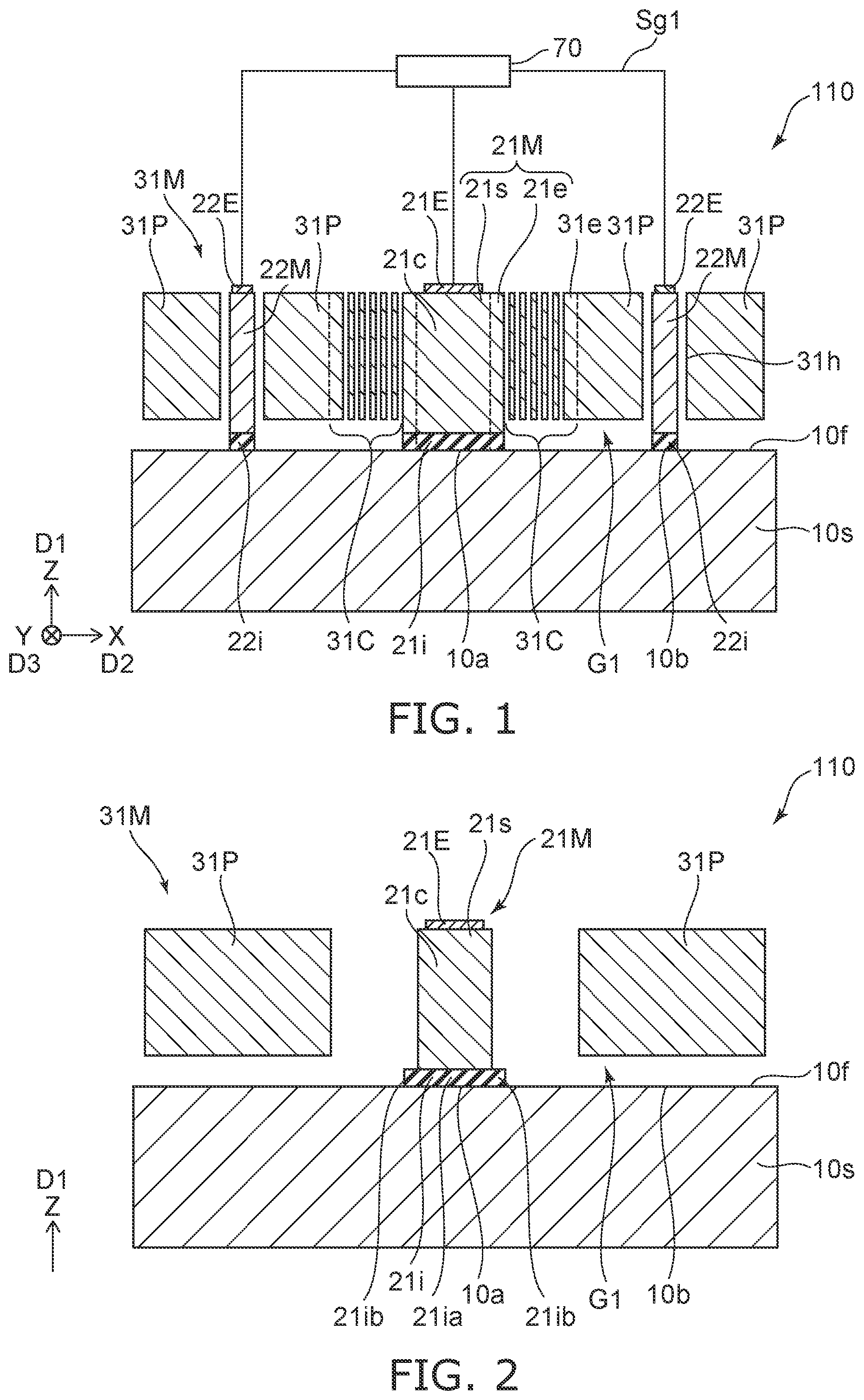
As shown in , a sensor 110 according to the embodiment includes a base body 10 s , a support member 21 M, and a movable member 31 M.
The base body 10 s includes a first face 10 f . The first face 10 f includes a first base region 10 a . The support member 21 M is fixed to the first base region 10 a.
As shown in , the support member 21 M includes a support portion 21 s and an extending portion 21 e . The extending portion 21 e is connected to the support portion 21 s.
As shown in , a first direction D 1 from the first base region 10 a to the support portion 21 s is defined as a Z-axis direction. A direction perpendicular to the Z-axis direction is defined as an X-axis direction. A direction perpendicular to the Z-axis direction and the X-axis direction is defined as a Y-axis direction.
As shown in , the extending portion 21 e extends along a second direction D 2 . The second direction D 2 crosses the first direction D 1 . The second direction D 2 is, for example, the X-axis direction.
As shown in , a width of the support portion 21 s in a third direction D 3 is defined as a first width w 1 . The third direction D 3 crosses a plane including the first direction D 1 and the second direction D 2 . The third direction D 3 is, for example, the Y-axis direction. A width of the extending portion 21 e in the third direction D 3 is defined as a second width w 2 . The first width w 1 is wider than the second width w 2 .
As shown in , the movable member 31 M is supported by the extending portion 21 e . A first gap G 1 is provided between the first face 10 f and the movable member 31 M.
In the embodiment, at least a part of the extending portion 21 e that supports the movable member 31 M is fixed to the base body 10 s . The extending portion 21 e is stable. For example, deflection effects due to gravity can be reduced. For example, vibration resistance can be improved. For example, stable resonance characteristics of the movable member 31 M can be obtained. A sensor with stable characteristics can be provided.
For example, an insulating layer is provided on the base body 10 s , and a member that becomes the movable member 31 M is provided on the insulating layer. The movable member 31 M and the first gap G 1 are formed by removing a portion of the member that becomes the movable member 31 M and further removing a portion of the insulating layer. In the process of forming the movable member 31 M, the insulating layer may be excessively removed. For example, if no insulating layer is provided between the entire extending portion 21 e and the base body 10 s , the extending portion 21 e is unstable.
In the embodiment, an insulating layer is provided between at least part of the extending portion 21 e and the base body 10 s , and at least part of the extending portion 21 e is fixed to the base body 10 s . In the embodiment, there is a wide margin for processing in the process of forming the movable member 31 M. Stable resonance characteristics of the movable member 31 M are obtained by the stable extending portion 21 e . For example, processing variations are suppressed. A sensor with stable characteristics can be provided.
As shown in , in this example, the support member 21 M includes a support conductive portion 21 c and a support insulating portion 21 i . As shown in , a portion 21 ca of the support conductive portion 21 c serves as the support portion 21 s . Another portion 21 cb of the support conductive portion 21 c becomes the extending portion 21 e . The portion 21 ia of the support insulating portion 21 i is provided between the first face 10 f and the portion 21 ca of the support conductive portion 21 c . Another portion 21 ib of the support insulating portion 21 i is provided between the first face 10 f and another portion 21 cb of the support conductive portion 21 c.
The first width w 1 may be, for example, a length of the portion 21 ia of the support insulating portion 21 i in the third direction D 3 . The second width w 2 may be, for example, a length of the other portion 21 ib of the support insulating portion 21 i in the third direction D 3 .
For example, the support insulating portion 21 i includes at least one selected from the group consisting of oxygen and nitrogen and at least one selected from the group consisting of silicon and aluminum. The support insulating portion 21 i includes, for example, silicon oxide.
For example, the support conductive portion 21 c includes silicon. The support conductive portion 21 c may include conductive silicon.
In the embodiment, the first width w 1 is not less than 2 times and not more than 1000 times the second width w 2 . By the extending portion 21 e being thin, movement (vibration) of the movable member 31 M becomes easy.
As shown in , in this example, the movable member 31 M includes a first connecting portion 31 C and a first movable portion 31 P. The first connecting portion 31 C is located between the extending portion 21 e and a part of the first movable portion 31 P. As shown in , the first connecting portion 31 C is supported by the extending portion 21 e . The first connecting portion 31 C supports the first movable portion 31 P.
As shown in , the first connecting portion 31 C may have a meander structure. A stable spring function is obtained.
As shown in , the movable member 31 M may further include a first movable extending portion 31 e . The first movable extending portion 31 e extends along the second direction D 2 . The first movable extending portion 31 e is provided between the first connecting portion 31 C and the first movable portion 31 P. A direction from the extending portion 21 e to the first movable extending portion 31 e is along the second direction D 2 . The first gap G 1 is provided between the first face 10 f and the first connecting portion 31 C, between the first face 10 f and the first movable extending portion 31 e , and between the first face 10 f and the first movable portion 31 P.
As shown in , the first movable portion 31 P is provided around the support portion 21 s on a plane (for example, the X-Y plane) crossing the first direction D 1 . The first movable portion 31 P is, for example, annular.
As shown in , a plurality of extending portions 21 e and a plurality of first connecting portions 31 C are provided. One of the multiple first connecting portion s 31 C is connected to one of the multiple extending portions 21 e . The extending direction of the extending portion 21 e is a radial direction centered on the support portion 21 s . The second direction D 2 is one of the radial directions.
As shown in , the sensor 110 may further include fixed conductive member 22 M. As shown in , the first face 10 f further includes a second base region 10 b . The fixed conductive member 22 M is fixed to the second base region 10 b . The fixed conductive member 22 M faces the movable member 31 M in a direction crossing the first direction D 1 .
In this example, the first movable portion 31 P includes a hole 31 h along the first direction D 1 . The fixed conductive member 22 M passes through the hole 31 h . As shown in , a plurality of fixed conductive members 22 M and a plurality of holes 31 h may be provided. The plurality of fixed conductive members 22 M may be provided on a circumference centered on the support portion 21 s . One of the plurality of fixed conductive members 22 M passes through one of the plurality of holes 31 h . The support portion 21 s is provided between one of the plurality of fixed conductive members 22 M and another one of the plurality of fixed conductive members 22 M. The one of the plurality of fixed conductive members 22 M and the other one of the plurality of fixed conductive members 22 M are arranged along the second direction D 2 or the third direction D 3 .
For example, when a voltage is applied between the first movable portion 31 P and the fixed conductive member 22 M, the first movable portion 31 P is displaced in the X-Y plane. For example, when an AC voltage is applied, the first movable portion 31 P vibrates.
The first movable portion 31 P is electrically connected to the support portion 21 s via the first connecting portion 31 C and the extending portion 21 e . When a voltage is applied between the support portion 21 s and the fixed conductive member 22 M, the voltage is applied between the first movable portion 31 P and the fixed conductive member 22 M.
As shown in , a support portion electrode 21 E electrically connected to the support portion 21 s (support member 21 M) may be provided. A fixed electrode 22 E electrically connected to the fixed conductive member 22 M may be provided. As shown in , the controller 70 may be connected to these electrodes. The controller 70 may be included in the sensor 110 . The controller 70 may be provided separately from the sensor 110 .
The controller 70 is configured to apply an AC signal Sg 1 between the support member 21 M and the fixed conductive member 22 M to vibrate the movable member 31 M (the first movable portion 31 P).
When a rotational force is applied to the movable member 31 M (the first movable portion 31 P) from the outside, the vibration state of the movable member 31 M (the first movable part 31 P) is changed. The change in vibration state is based on, for example, Coriolis force.
The controller 70 is configured to detect the state of vibration of the movable member 31 M. The state of vibration of the movable member 31 M changes according to the rotational force applied to the movable member 31 M. By detecting the state of vibration of the movable member 31 M, the rotational force applied to the movable member 31 M can be detected.
As shown in , a part of the support insulating portion 21 i may protrude with respect to the support conductive portion 21 c in a direction crossing the direction (first direction D 1 ) from the first base region 10 a to the support member 21 M.
is a schematic plan view illustrating part of the sensor according to the first embodiment.
As shown in , in the sensor 110 , the outer edge of the support insulating portion 21 i may protrude with respect to the support conductive portion 21 c . For example, in the portion corresponding to the extending portion 21 e , the outer edge of the support insulating portion 21 i may protrude in a curved shape with respect to the support conductive portion 21 c . In the example shown in , a part of the support conductive portion 21 c corresponding to the extending portion 21 e does not overlap the support insulating portion 21 i in the first direction D 1 . is a schematic plan view illustrating a part of a sensor according to the first embodiment.
As shown in , in a sensor 111 according to the embodiment, in a part corresponding to the extending portion 21 e , the outer edge of the support insulating portion 21 i may protrude with respect to the support conductive portion 21 c.
is a schematic plan view illustrating a part of a sensor according to the first embodiment.
is a schematic cross-sectional view illustrating a part of the sensor according to the first embodiment.
These figures illustrate a sensor 112 according to the embodiment. In the sensor 112 , the amount of protrusion of the outer edge of the support insulating portion 21 i is smaller than that of the sensor 110 and the like.
In this case, as shown in , a second gap G 2 may be provided between the base body 10 s and a part of the extending portion 21 e . In the sensor 112 , most of the extending portion 21 e is stably fixed to the base body 10 s . Stable resonance characteristics of the movable member 31 M are obtained by the stable extending portion 21 e.
is a schematic plan view illustrating a part of a sensor according to the first embodiment.
As shown in , in a sensor 113 according to the embodiment, the amount of protrusion of the outer edge of the support insulating portion 21 i is smaller than that of the sensor 112 . In the sensor 113 , a part of the extending portion 21 e is stably fixed to the base body 10 s . Stable resonance characteristics of the movable member 31 M are obtained by the stable extending portion 21 e.
The configurations of the sensors 111 to 113 may be the same as those of the sensor 110 except for the above.
The sensor 113 includes the base body 10 s (see ), the support member 21 M (see ), and the movable member 31 M (see ). The base body 10 s includes the first face 10 f including a first base region 10 a . The support member 21 M is fixed to the first base region 10 a . As shown in , the support member 21 M includes the support conductive portion 21 c and the support insulating portion 21 i . As shown in , the portion 21 ia of the support insulating portion 21 i is provided between the first face 10 f and the support conductive portion 21 c . The other portion 21 ib of the support insulating portion 21 i does not overlap the support conductive portion 21 c . As shown in , the movable member 31 M is supported by the support member 21 M. The first gap G 1 is provided between the first face 10 f and the movable member 31 M. In the sensor 113 , the other portion 21 ib of the support insulating portion 21 i protrudes with respect to the support conductive portion 21 c in a direction crossing the direction (first direction D 1 ) from the first base region 10 a to the support member 21 M.
is a schematic cross-sectional view illustrating a part of a sensor according to the first embodiment.
As shown in , in a sensor 114 according to the embodiment, a side face of the other portion 21 ib of the support insulating portion 21 i may be curved. Except for this, the configuration of the sensor 114 may be the same as the configuration of the sensor 110 .
In the sensor 114 , the other portion 21 ib of the support insulating portion 21 i includes a portion facing the first face 10 f and a portion facing the other portion 21 cb of the support conductive portion 21 c . For example, the length along the second direction D 2 of the portion facing the first face 10 f is shorter than the length along the second direction D 2 of the portion facing the other portion 21 cb of the support conductive portion 21 c . By such a shape, the stress concentration is relaxed. It is easy to obtain more stable characteristics.
Second Embodiment
A second embodiment relates to an electronic device.
is a schematic diagram illustrating an electronic device according to a second embodiment.
As shown in , an electronic device 310 according to the embodiment includes the sensors according to the embodiments and the circuit processor 170 . In the example of , the sensor 110 (or the sensor device 210 ) is drawn as the sensor. The circuit processor 170 is configured to control a circuit 180 based on the signal 51 obtained from the sensor. The circuit 180 is, for example, a control circuit for a drive device 185 . According to the embodiment, for example, the circuit 180 for controlling the drive device 185 can be controlled with high accuracy.
A to 13 H are schematic views illustrating applications of the electronic device.
As shown in A , the electronic device 310 may be at least a portion of a robot. As shown in B , the electronic device 310 may be at least a portion of a machining robot provided in a manufacturing plant, etc. As shown in C , the electronic device 310 may be at least a portion of an automatic guided vehicle inside a plant, etc. As shown in D , the electronic device 310 may be at least a portion of a drone (an unmanned aircraft). As shown in E , the electronic device 310 may be at least a portion of an airplane. As shown in F , the electronic device 310 may be at least a portion of a ship. As shown in G , the electronic device 310 may be at least a portion of a submarine. As shown in H , the electronic device 310 may be at least a portion of an automobile. The electronic device 310 according to the third embodiment may include, for example, at least one of a robot or a moving body.
The embodiment may include the following configuration (for example, technical proposals).
Configuration 1
A sensor, comprising:
•
• a base body including a first face including a first base region; • a support member fixed to the first base region, the support member including a support portion and an extending portion, the extending portion being connected to the support portion, the extending portion extending along a second direction crossing a first direction from the first base region to the support portion, a first width of the support portion in a third direction crossing a plane including the first direction and the second direction being wider than a second width of the extending portion in the third direction; and • a movable member supported by the extending portion, a first gap being provided between the first face and the movable member. Configuration 2
The sensor according to Configuration 1, wherein a second gap is provided between the base body and a part of the extending portion.
Configuration 3
The sensor according to Configuration 1 or 2, wherein
•
• the support member includes a support conductive portion and a support insulating portion, • a portion of the support conductive portion serves as the supporting portion, • another portion of the support conductive portion serves as the extending portion, • a portion of the support insulating portion is provided between the first face and the portion of the support conductive portion, and • another portion of the support insulating portion is provided between the first face and the other portion of the support conductive portion. Configuration 4
The sensor according to Configuration 3, wherein
•
• the first width is a length of the portion of the support insulating portion in the third direction, and • the second width is a length of the other portion of the support insulating portion in the third direction. Configuration 5
The sensor according to Configuration 4, wherein the support insulating portion includes at least one selected from the group consisting of oxygen and nitrogen, and at least one selected from the group consisting of silicon and aluminum.
Configuration 6
The sensor according to Configuration 5, wherein the supporting conductive portion includes silicon.
Configuration 7
The sensor according to any one of Configurations 1 to 6, wherein the first width is not less than 2 times and not more than 1000 times the second width.
Configuration 8
The sensor according to any one of Configurations 1 to 7, wherein
•
• the movable member includes a first connection portion and a first movable portion, • the first connecting portion is located between the extending portion and a part of the first movable portion, • the first connection portion is supported by the extending portion, and • the first connection portion supports the first movable portion. Configuration 9
The sensor according to Configuration 8, wherein the first connection portion has a meander structure.
Configuration 10
The sensor according to Configuration 8 or 9, wherein
•
• the movable member further includes a first movable extending portion, • the first movable extending portion is provided between the first connecting portion and the first movable portion, and • a direction from the extending portion to the first movable extending portion is along the second direction. Configuration 11
The sensor according to any one of Configurations 8 to 10, wherein the first movable portion is provided around the support portion in a plane crossing the first direction.
Configuration 12
The sensor according to Configuration 11, wherein
•
• a plurality of the extending portions and a plurality of the first connecting portions are provided, and • one of the plurality of first connecting portions is connected to one of the plurality of extending portions. Configuration 13
The sensor according to any one of Configurations 8 to 12, further comprising a fixed conductive member,
•
• the first face further including a second base region, • the fixed conductive member being fixed to the second base region, and • the fixed conductive member facing the movable member in a direction crossing the first direction. Configuration 14
The sensor according to Configuration 13, wherein
•
• the first movable portion includes a hole along the first direction, and • the fixed conductive member passes through the hole. Configuration 15
The sensor according to Configuration 13 or 14, further comprising a controller,
•
• the controller being configured to vibrate the movable member by applying an AC signal between the support member and the fixed conductive member. Configuration 16
The sensor according to Configuration 15, wherein the controller is configured to detect a state of a vibration of the movable member being configured to change according to a rotational force applied to the movable member.
Configuration 17
A sensor, comprising:
•
• a base body including a first face including a first base region; • a support member fixed to the first base region, the support member including a support conductive portion and a support insulating portion, a portion of the support insulating portion being provided between the first face and the support conductive portion, another portion of the support insulating portion not overlapping the support conductive portion; and • a movable member supported by the support member, a first gap being provided between the first face and the movable member. Configuration 18
The sensor according to Configuration 17, wherein the other portion of the support insulating portion protrudes from the support conductive portion in a direction crossing a first direction from the first base region to the support member.
Configuration 19
An electronic device, comprising:
•
• the sensor according to any one of Configurations 1 to 18; and • a circuit controller configured to control a circuit based on a signal obtained from the sensor. Configuration 20
The device according to Configuration 19, wherein the electronic device includes at least one of a robot or a mobile body.
According to the embodiments, it is possible to provide a sensor and an electronic device with stable characteristics.
Hereinabove, exemplary embodiments of the invention are described with reference to specific examples. However, the embodiments of the invention are not limited to these specific examples. For example, one skilled in the art may similarly practice the invention by appropriately selecting specific configurations of components included in sensors such as base bodies, support portion, movable portion, electrodes, insulating portion, circuit portion, controller, etc., from known art. Such practice is included in the scope of the invention to the extent that similar effects thereto are obtained.
Further, any two or more components of the specific examples may be combined within the extent of technical feasibility and are included in the scope of the invention to the extent that the purport of the invention is included.
Moreover, all sensors and electronic devices practicable by an appropriate design modification by one skilled in the art based on the sensors and electronic devices described above as embodiments of the invention also are within the scope of the invention to the extent that the spirit of the invention is included.
Various other variations and modifications can be conceived by those skilled in the art within the spirit of the invention, and it is understood that such variations and modifications are also encompassed within the scope of the invention.
While certain embodiments have been described, these embodiments have been presented by way of example only, and are not intended to limit the scope of the inventions. Indeed, the novel embodiments described herein may be embodied in a variety of other forms; furthermore, various omissions, substitutions and changes in the form of the embodiments described herein may be made without departing from the spirit of the inventions. The accompanying claims and their equivalents are intended to cover such forms or modifications as would fall within the scope and spirit of the invention.
Figures (10)
Citations
This patent cites (36)
- US5864064
- US10767992
- US11796319
- US2013/0049212
- US2016/0097792
- US2017/0227572
- US2019/0162750
- US2020/0039814
- US2020/0067479
- US2020/0284582
- US2020/0363205
- US2021/0063432
- US2021/0381831
- US2021/0396780
- US2022/0137085
- US2022/0259035
- US2022/0268583
- US2022/0276052
- US2022/0326013
- US2023/0062441
- US2023/0143243
- USH09-145740
- US2009-130328
- US2012-215505
- US2020-144065
- US2020-187018
- US2021-16923
- US2021-192012
- US2022-1828
- US2022-74658
- US2022-125454
- US2022-129691
- US2022-131004
- US2022-162641
- US2023-36260
- US2023-69581