Abstract
An inertial force sensor may comprise: a base; a first block including an inclined surface that is inclined with respect to a base surface; a second block including an inclined surface that is inclined with respect to the base surface; a third block including an inclined surface that is inclined with respect to the base surface; a fourth block including an inclined surface that is inclined with respect to the base surface; and a connector configured to physically connect the first, second, third, and fourth blocks. In this inertial force sensor, the first and second blocks are aligned along a first direction parallel to the base surface with their inclined surfaces both facing inward or outward, and the third and fourth blocks are aligned along a second direction parallel to the base surface and orthogonal to the first direction with their inclined surfaces both facing inward or outward.
Claims (20)
1. An inertial force sensor comprising: a base; a first block mounted on the base and including a bottom surface that is substantially parallel to a surface of the base, a rear surface that is substantially perpendicular to the surface of the base, and an inclined surface that is inclined with respect to the surface of the base and connects the bottom surface and the rear surface; a second block mounted on the base and including a bottom surface that is substantially parallel to the surface of the base, a rear surface that is substantially perpendicular to the surface of the base, and an inclined surface that is inclined with respect to the surface of the base and connects the bottom surface and the rear surface; a third block mounted on the base and including a bottom surface that is substantially parallel to the surface of the base, a rear surface that is substantially perpendicular to the surface of the base, and an inclined surface that is inclined with respect to the surface of the base and connects the bottom surface and the rear surface; a fourth block mounted on the base and including a bottom surface that is substantially parallel to the surface of the base, a rear surface that is substantially perpendicular to the surface of the base, and an inclined surface that is inclined with respect to the surface of the base and connects the bottom surface and the rear surface; a first single-axis inertial force sensor arranged on the inclined surface of the first block; a second single-axis inertial force sensor arranged on the inclined surface of the second block; a third single-axis inertial force sensor arranged on the inclined surface of the third block; a fourth single-axis inertial force sensor arranged on the inclined surface of the fourth block; a connector configured to physically connect the first, second, third, and fourth blocks; and a circuit arithmetic processing and output module configured to execute an arithmetic algorithm that processes an output from each of the single-axis inertial force sensors and an output algorithm that outputs multiple-axis inertial force obtained by the arithmetic algorithm, wherein: the first and second blocks are aligned along a first direction parallel to the surface of the base with their inclined surfaces both facing inward toward a center of the surface of the base or both facing outward toward peripherals of the surface of the base, and the third and fourth blocks are aligned along a second direction parallel to the surface of the base and orthogonal to the first direction with their inclined surfaces both facing inward toward the center of the surface of the base or both facing outward toward peripherals of the surface of the base.
5. An inertial force sensor comprising: a base; a first block mounted on the base and including an inclined surface that is inclined with respect to a surface of the base and a recess defined on a surface of the first block other than the inclined surface; a second block mounted on the base and including an inclined surface that is inclined with respect to the surface of the base and a recess defined on a surface of the second block other than the inclined surface; a third block mounted on the base and including an inclined surface that is inclined with respect to the surface of the base and a recess defined on a surface of the third block other than the inclined surface; a fourth block mounted on the base and including an inclined surface that is inclined with respect to the surface of the base and a recess defined on a surface of the fourth block other than the inclined surface; a first single-axis inertial force sensor arranged on the inclined surface of the first block; a second single-axis inertial force sensor arranged on the inclined surface of the second block; a third single-axis inertial force sensor arranged on the inclined surface of the third block; a fourth single-axis inertial force sensor arranged on the inclined surface of the fourth block; a connector including projections configured to fit the recesses of the first, second, third, and fourth blocks and configured to physically connect the first, second, third, and fourth blocks; and a circuit arithmetic processing and output module configured to execute an arithmetic algorithm that processes an output from each of the single-axis inertial force sensors and an output algorithm that outputs multiple-axis inertial force obtained by the arithmetic algorithm, wherein: the first and second blocks are aligned along a first direction parallel to the surface of the base with their inclined surfaces both facing inward toward a center of the surface of the base or both facing outward toward peripherals of the surface of the base, and the third and fourth blocks are aligned along a second direction parallel to the surface of the base and orthogonal to the first direction with their inclined surfaces both facing inward toward the center of the surface of the base or both facing outward toward peripherals of the surface of the base.
10. An inertial force sensor comprising: a base; a first block mounted on the base and including an inclined surface that is inclined with respect to a surface of the base, and a recess and a reference projection arranged on a surface of the first block other than the inclined surface; a second block mounted on the base and including an inclined surface that is inclined with respect to the surface of the base and a recess defined on a surface of the second block other than the inclined surface; a third block mounted on the base and including an inclined surface that is inclined with respect to the surface of the base and a recess defined on a surface of the third block other than the inclined surface; a fourth block mounted on the base and including an inclined surface that is inclined with respect to the surface of the base and a recess defined on a surface of the fourth block other than the inclined surface; a first single-axis inertial force sensor arranged on the inclined surface of the first block; a second single-axis inertial force sensor arranged on the inclined surface of the second block; a third single-axis inertial force sensor arranged on the inclined surface of the third block; a fourth single-axis inertial force sensor arranged on the inclined surface of the fourth block; a connector including projections configured to fit the recesses of two of the first, second, third, and fourth blocks and configured to physically connect the blocks; and a circuit arithmetic processing and output module configured to execute an arithmetic algorithm that processes an output from each of the single-axis inertial force sensors and an output algorithm that outputs multiple-axis inertial force obtained by the arithmetic algorithm, wherein: the first and second blocks are aligned along a first direction parallel to the surface of the base with their inclined surfaces both facing inward toward a center of the surface of the base, and the third and fourth blocks are aligned along a second direction parallel to the surface of the base and orthogonal to the first direction with their inclined surfaces both facing inward toward the center of the surface of the base.
17. An inertial force sensor comprising: a base; a first block mounted on the base and including an inclined surface that is inclined with respect to a surface of the base and a metal pad arranged on a surface of the first block other than the inclined surface; a second block mounted on the base and including an inclined surface that is inclined with respect to the surface of the base and a recess defined on a surface of the second block other than the inclined surface; a third block mounted on the base and including an inclined surface that is inclined with respect to the surface of the base and a recess defined on a surface of the third block other than the inclined surface; a fourth block mounted on the base and including an inclined surface that is inclined with respect to the surface of the base and a recess defined on a surface of the fourth block other than the inclined surface; a first single-axis inertial force sensor arranged on the inclined surface of the first block; a second single-axis inertial force sensor arranged on the inclined surface of the second block; a third single-axis inertial force sensor arranged on the inclined surface of the third block; a fourth single-axis inertial force sensor arranged on the inclined surface of the fourth block; a connector including metal connection pads welded to the metal pad of each block and configured to physically connect the first, second, third, and fourth blocks; and a circuit arithmetic processing and output module configured to execute an arithmetic algorithm that processes an output from each of the single-axis inertial force sensors and an output algorithm that outputs multiple-axis inertial force obtained by the arithmetic algorithm, wherein: the first and second blocks are aligned along a first direction parallel to the surface of the base with their inclined surfaces both facing inward toward a center of the surface of the base, and the third and fourth blocks are aligned along a second direction parallel to the surface of the base and orthogonal to the first direction with their inclined surfaces both facing inward toward the center of the surface of the base.
Show 16 dependent claims
2. The inertial force sensor according to claim 1 , wherein the first, second, third, and fourth blocks are identical in shape.
3. The inertial force sensor according to claim 1 , wherein the first, second, third, and fourth blocks are constituted of a same resin material.
4. The inertial force sensor according to claim 1 , wherein the connector is constituted of a resin material that is a same material that constitutes the blocks.
6. The inertial force sensor according to claim 5 , wherein the connector is configured of a first connector, a second connector, a third connector, and a fourth connector, the first connector connects the first and third blocks, the second connector connects the second and fourth blocks, the third connector connects the third and second blocks, and the fourth connector connects the fourth and first blocks.
7. The inertial force sensor according to claim 5 , wherein the first, second, third, and fourth blocks are identical in shape.
8. The inertial force sensor according to claim 5 , wherein the first, second, third, and fourth blocks are constituted of a same resin material.
9. The inertial force sensor according to claim 5 , wherein the connector is constituted of a resin material that is a same material that constitutes the blocks.
11. The inertial force sensor according to claim 10 , wherein the reference projections are in contact with a surface of the connector.
12. The inertial force sensor according to claim 10 , wherein the reference projection of each block is in contact with the reference projection of another block.
13. The inertial force sensor according to claim 10 , wherein more than two reference projections are further arranged on the surface of each block.
14. The inertial force sensor according to claim 10 , wherein the first, second, third, and fourth blocks are identical in shape.
15. The inertial force sensor according to claim 10 , wherein the first, second, third, and fourth blocks are constituted of a same resin material.
16. The inertial force sensor according to claim 10 , wherein the connector is constituted of a resin material that is a same material that constitutes the blocks.
18. The inertial force sensor according to claim 17 , wherein the first, second, third, and fourth blocks are identical in shape.
19. The inertial force sensor according to claim 17 , wherein the first, second, third, and fourth blocks are constituted of a same resin material.
20. The inertial force sensor according to claim 17 , wherein the connector is constituted of a resin material that is a same material that constitutes the blocks.
Full Description
Show full text →
REFERENCE TO RELATED APPLICATIONS
This application claims priority to Japanese patent application No. 2022-048963, filed on Mar. 24, 2022, the entire contents of which are incorporated herein by reference.
BACKGROUND ART
The art disclosed herein relates to inertial force sensors.
JP 2013-44645 A describes a physical quantity sensor module provided with three physical quantity sensors. Specifically, in JP 2013-44645 A, the physical quantity sensors are each arranged on a surface of corresponding one of three triangular blocks, and these three blocks are mounted on a circuit board such that the physical quantity sensors are oriented toward different directions from one another.
DESCRIPTION
The sensor module described in JP 2013-44645 A fixes the three blocks on the circuit board, thus it is difficult to implement relative positions between those sensors precisely as designed. If the relative positions of the sensors are displaced from their designed values, detection accuracy decreases. Due to this, in the sensor module configured to detect physical quantities using multiple sensors, the relative positions of the sensors need to be controlled with high precision to enable high-accuracy detection. The description herein aims to provide an inertial force sensor with improved detection accuracy.
An aspect of an inertial force sensor disclosed herein may comprise a base; a first block mounted on the base and including an inclined surface that is inclined with respect to a surface of the base; a second block mounted on the base and including an inclined surface that is inclined with respect to the surface of the base; a third block mounted on the base and including an inclined surface that is inclined with respect to the surface of the base; a fourth block mounted on the base and including an inclined surface that is inclined with respect to the surface of the base; a first single-axis inertial force sensor arranged on the inclined surface of the first block; a second single-axis inertial force sensor arranged on the inclined surface of the second block; a third single-axis inertial force sensor arranged on the inclined surface of the third block; a fourth single-axis inertial force sensor arranged on the inclined surface of the fourth block; a connector configured to physically connect the first, second, third, and fourth blocks; and a circuit arithmetic processing and output module configured to execute an arithmetic algorithm that processes an output from each of the single-axis inertial force sensors and an output algorithm that outputs multiple-axis inertial force obtained by the arithmetic algorithm, wherein the first and second blocks are aligned along a first direction parallel to the surface of the base with their inclined surfaces both facing inward or both facing outward, and the third and fourth blocks are aligned along a second direction parallel to the surface of the base and orthogonal to the first direction with their inclined surfaces both facing inward or both facing outward.
The inertial force sensor as above has the respective blocks connected by the connector. Due to this, relative positions of the respective blocks, that is, relative positions of the single-axis inertial force sensors can be positioned precisely at their designed values. The inertial force sensor has the respective single-axis inertial force sensors arranged on the inclined surfaces of the blocks, with the first and second blocks arranged along the first direction and the third and fourth blocks arranged along the second direction (direction orthogonal to the first direction). Due to this, the inertial force sensor can detect 3-axis angular velocity.
shows a perspective view of an inertial force sensor of a first embodiment.
A to 2 F show shapes of respective surfaces of a block.
shows a perspective view of a connector.
shows how block sensors are connected to the connector.
shows a detailed diagram of the block sensor.
A and 6 B show diagrams for explaining measurement principle of 3-axis angular velocity.
shows a detected 3-axis angular velocity characteristic of the inertial force sensor.
shows a detected 3-axis angular velocity characteristic of the inertial force sensor.
shows a detected 3-axis angular velocity characteristic of the inertial force sensor.
schematically shows an internal configuration of the inertial force sensor.
shows a perspective view of an inertial force sensor of a second embodiment.
A to 12 F show shapes of respective surfaces of a block.
shows a perspective view of a connector.
shows how block sensors are connected to the connector.
shows a perspective view of an inertial force sensor of a third embodiment.
A to 16 F show shapes of respective surfaces of a block.
shows how block sensors are connected to a connector.
shows a perspective view of an inertial force sensor of a fourth embodiment.
shows a perspective view of a connector.
shows how block sensors are connected to the connector.
shows a perspective view of an inertial force sensor of a fifth embodiment.
shows how block sensors are connected to a connector.
shows a perspective view of an inertial force sensor of a sixth embodiment.
A to 24 F show shapes of respective surfaces of a block.
shows how block sensors are connected to a connector.
shows how the block sensors are connected to the connector.
is a cross-sectional view along a line C 27 -C 27 in , and is a diagram explaining a contact state of the block sensors in detail.
is a diagram for explaining a portion measured in surface precision measurement.
is a diagram for explaining the portion measured in the surface precision measurement.
shows results of the surface precision measurement.
shows a perspective view of an inertial force sensor of a seventh embodiment.
shows a perspective view of a connector.
shows a perspective view of an inertial force sensor of an eighth embodiment.
A to 34 F show shapes of respective surfaces of a block.
shows a plan view of a connector.
shows a plan view of a supporting jig.
shows how block sensors are connected to the connector.
EMBODIMENT
An aspect of an inertial force sensor disclosed herein may comprise: a base; a first block mounted on the base and including an inclined surface that is inclined with respect to a surface of the base and a recess defined on a surface different from the inclined surface; a second block mounted on the base and including an inclined surface that is inclined with respect to the surface of the base and a recess defined on a surface different from the inclined surface; a third block mounted on the base and including an inclined surface that is inclined with respect to the surface of the base and a recess defined on a surface different from the inclined surface; a fourth block mounted on the base and including an inclined surface that is inclined with respect to the surface of the base and a recess defined on a surface different from the inclined surface; a first single-axis inertial force sensor arranged on the inclined surface of the first block; a second single-axis inertial force sensor arranged on the inclined surface of the second block; a third single-axis inertial force sensor arranged on the inclined surface of the third block; a fourth single-axis inertial force sensor arranged on the inclined surface of the fourth block; a connector including projections configured to fit the recesses of the first, second, third, and fourth blocks and configured to physically connect the first, second, third, and fourth blocks; and a circuit arithmetic processing and output module configured to execute an arithmetic algorithm that processes an output from each of the single-axis inertial force sensors and an output algorithm that outputs multiple-axis inertial force obtained by the arithmetic algorithm, wherein the first and second blocks are aligned along a first direction parallel to the surface of the base with their inclined surfaces both facing inward or both facing outward, and the third and fourth blocks are aligned along a second direction parallel to the surface of the base and orthogonal to the first direction with their inclined surfaces both facing inward or both facing outward.
This inertial force sensor fixes the respective blocks to the connector by fitting the recesses arranged on the blocks to the projections arranged on the connector. As a result, the respective blocks are connected by the connector and the relative positions of the respective blocks (relative positions of the single-axis inertial force sensors) can be positioned precisely at their designed values. This inertial force sensor also has the respective single-axis inertial force sensors arranged on the inclined surfaces of the blocks, with the first and second blocks arranged along the first direction and the third and fourth blocks arranged along the second direction (direction orthogonal to the first direction). Due to this, the inertial force sensor can detect 3-axis angular velocity.
An aspect of an inertial force sensor disclosed herein may comprise: a base; a first block mounted on the base and including an inclined surface that is inclined with respect to a surface of the base, and a recess and a reference projection arranged on a surface different from the inclined surface; a second block mounted on the base and including an inclined surface that is inclined with respect to the surface of the base, and a recess and a reference projection arranged on a surface different from the inclined surface; a third block mounted on the base and including an inclined surface that is inclined with respect to the surface of the base, and a recess and a reference projection arranged on a surface different from the inclined surface; a fourth block mounted on the base and including an inclined surface that is inclined with respect to the surface of the base, and a recess and a reference projection arranged on a surface different from the inclined surface; a first single-axis inertial force sensor arranged on the inclined surface of the first block; a second single-axis inertial force sensor arranged on the inclined surface of the second block; a third single-axis inertial force sensor arranged on the inclined surface of the third block; a fourth single-axis inertial force sensor arranged on the inclined surface of the fourth block; a connector including projections configured to fit the recesses of two of the first, second, third, and fourth blocks and configured to physically connect the blocks; and a circuit arithmetic processing and output module configured to execute an arithmetic algorithm that processes an output from each of the single-axis inertial force sensors and an output algorithm that outputs multiple-axis inertial force obtained by the arithmetic algorithm, wherein the first and second blocks are aligned along a first direction parallel to the surface of the base with their inclined surfaces both facing inward or both facing outward, and the third and fourth blocks are aligned along a second direction parallel to the surface of the base and orthogonal to the first direction with their inclined surfaces both facing inward or both facing outward.
This inertial force sensor also fixes the respective blocks to the connector by fitting the recesses arranged on the blocks to the projections arranged on the connector, by which the relative positions of the respective blocks (relative positions of the single-axis inertial force sensors) can be positioned precisely at their designed values. Further, this inertial force sensor has the reference projections arranged on the respective blocks. Due to this, when the blocks are fixed by the connector, a contact area between the surface of each block where the reference projection is arranged and the connector or another block can be reduced. As a result, even if surface precision of a surface of a counterpart contacting each block is low, the blocks can be made more robust against the influence of such low surface precision. That is, the blocks can be positioned with high accuracy regardless of the surface precision of the surfaces of the counterparts thereof contacting the respective blocks. Further, the inertial force sensor as above also has the respective single-axis inertial force sensors arranged on the inclined surfaces of the blocks, with the first and second blocks arranged along the first direction and the third and fourth blocks arranged along the second direction (direction orthogonal to the first direction). Due to this, the inertial force sensor can detect 3-axis angular velocity.
In the inertial force sensor as above, the reference projections may be in contact with a surface of the connector. The positions of the blocks thereby become more robust against the influence of surface precision of the surface of the connector, and the position of the blocks can be performed with high accuracy. Alternatively, the reference projections may each be in contact with the reference projection of another block. In other words, the blocks may be in contact with each other via their reference projections. In this case, the positions of the blocks become more robust against the influence of surface precision of the surfaces of the blocks, and the position of the blocks can be performed with high accuracy. In the inertial force sensor as above, three or more reference projections may be arranged on the surface of each block. Since each block contact the surface of its contact counterpart at three or more points, the positions of the blocks are thereby stabilized.
In the above inertial force sensor, the connector may be configured of a first connector, a second connector, a third connector, and a fourth connector. The first connector may connect the first and third blocks, the second connector may connect the second and fourth blocks, the third connector may connect the third and second blocks, and the fourth connector may connect the fourth and first blocks. Even with a configuration that uses a plurality of (four) connectors, the relative positions of the blocks can be positioned precisely as their designed values.
An aspect of an inertial force sensor disclosed herein may comprise: a base; a first block mounted on the base and including an inclined surface that is inclined with respect to a surface of the base and a metal pad arranged on a surface different from the inclined surface; a second block mounted on the base and including an inclined surface that is inclined with respect to the surface of the base and a metal pad arranged on a surface different from the inclined surface; a third block mounted on the base and including an inclined surface that is inclined with respect to the surface of the base and a metal pad arranged on a surface different from the inclined surface; a fourth block mounted on the base and including an inclined surface that is inclined with respect to the surface of the base and a metal pad arranged on a surface different from the inclined surface; a first single-axis inertial force sensor arranged on the inclined surface of the first block; a second single-axis inertial force sensor arranged on the inclined surface of the second block; a third single-axis inertial force sensor arranged on the inclined surface of the third block; a fourth single-axis inertial force sensor arranged on the inclined surface of the fourth block; a connector including metal connection pads configured to be welded to the metal pad of each block and configured to physically connect the first, second, third, and fourth blocks; and a circuit arithmetic processing and output module configured to execute an arithmetic algorithm that processes an output from each of the single-axis inertial force sensors and an output algorithm that outputs multiple-axis inertial force obtained by the arithmetic algorithm, wherein the first and second blocks are aligned along a first direction parallel to the surface of the base with their inclined surfaces both facing inward or both facing outward, and the third and fourth blocks are aligned along a second direction parallel to the surface of the base and orthogonal to the first direction with their inclined surfaces both facing inward or both facing outward.
The above inertial force sensor also has the respective blocks connected by the connector. Due to this, the relative positions of the blocks, that is, the relative positions of the single-axis inertial force sensors can be positioned precisely as their designed values. Further, since the metal pads and the connection pads are welded, each block can be firmly fixed to the connector. The relative positions of the blocks can be suppressed from being displaced after having connected the blocks to the connector (after the blocks have been positioned). The inertial force sensor has the respective single-axis inertial force sensors arranged on the inclined surfaces of the blocks, with the first and second blocks arranged along the first direction and the third and fourth blocks arranged along the second direction (direction orthogonal to the first direction). Due to this, the inertial force sensor can detect 3-axis angular velocity.
In the inertial force sensor as above, the first, second, third, and fourth blocks may have a same shape. Types of components of the inertial force sensor can be reduced, and manufacturing cost of the inertial force sensor can thereby be reduced.
In the inertial force sensor as above, the first, second, third, and fourth blocks may be constituted of a same resin material. By using the resin material, weight of each block is reduced, and weight of the inertial force sensor can be reduced. Further, by using the resin material, the blocks can be produced easily with high precision even if they have complicated shapes.
In the inertial force sensor as above, the connector may be constituted of a resin material that is a same material that constitute the blocks. The weight of the inertial force sensor can be reduced also by constituting the connector by the resin material. Further, the same material (resin material) may be used for the connector and the blocks, by which types of materials for producing the inertial force sensor can be reduced. The manufacturing cost of the inertial force sensor can thereby be reduced.
First Embodiment
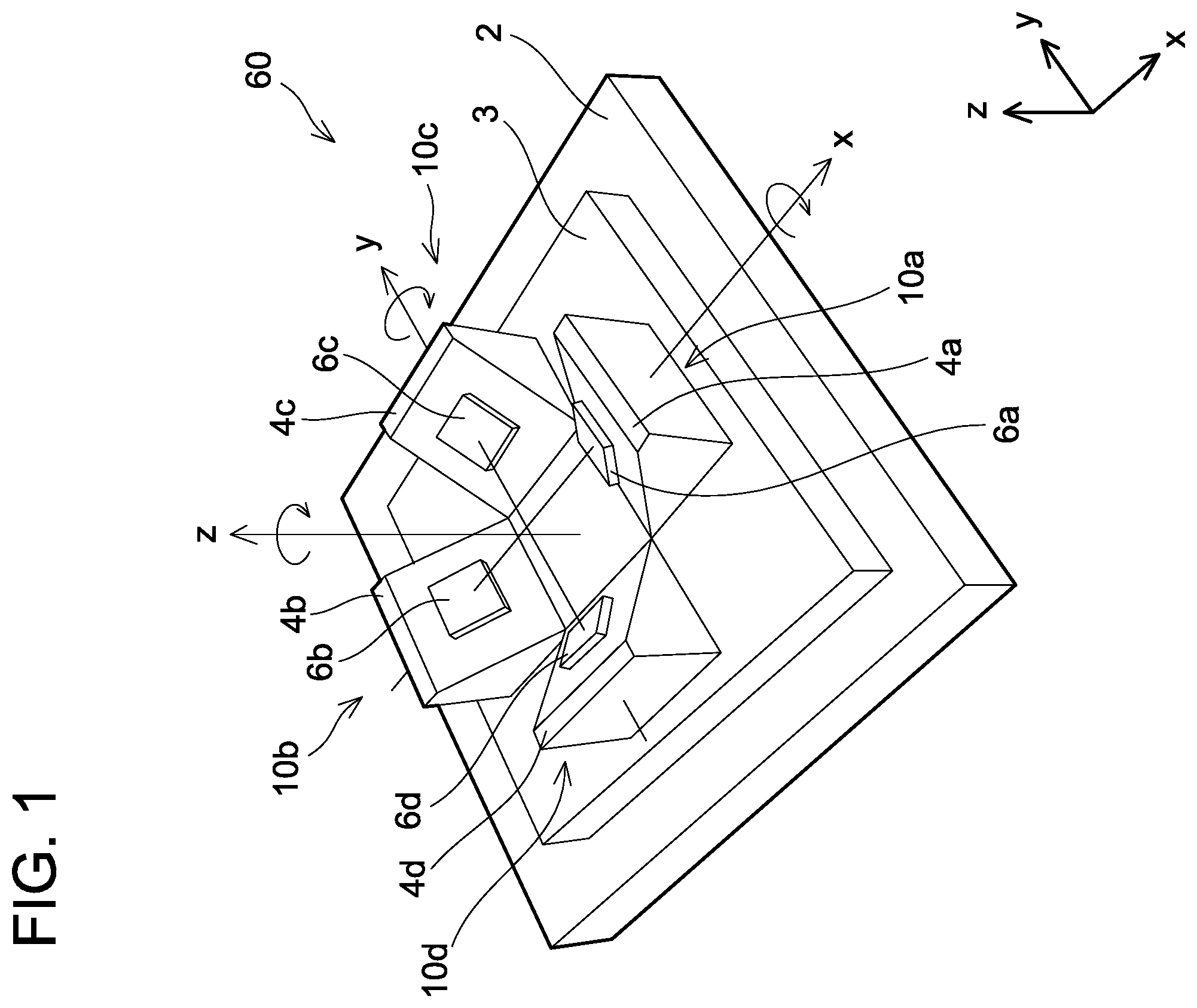
An inertial force sensor 60 will be described with reference to to 4 . As shown in , the inertial force sensor 60 comprises a base 2 , a connector 3 , a first block sensor 10 a , a second block sensor 10 b , a third block sensor 10 c , and a fourth block sensor 10 d . The first block sensor 10 a includes a first block 4 a and a first gyro sensor 6 a . The second block sensor 10 b includes a second block 4 b and a second gyro sensor 6 b . The third block sensor 10 c includes a third block 4 c and a third gyro sensor 6 c . The fourth block sensor 10 d includes a fourth block 4 d and a fourth gyro sensor 6 d . The first gyro sensor 6 a is an example of a first single-axis inertial force sensor, the second gyro sensor 6 b is an example of a second single-axis inertial force sensor, the third gyro sensor 6 c is an example of a third single-axis inertial force sensor, and the fourth gyro sensor 6 d is an example of a fourth single-axis inertial force sensor. The block sensors 10 a to 10 d are fixed (mounted) on the connector 3 . Further, the connector 3 is fixed (mounted) on a surface of the base 2 . The blocks 4 a to 4 d are constituted of a same material, and the block sensors 10 a to 10 d have substantially same structure as each other. Although details will be described later, the inertial force sensor 60 is a 3-axis angular velocity sensor (gyroscope) configured to detect angular velocity about x axis, y axis, and z axis.
The surface of the base 2 is parallel to a x-y plane. Further, the first block sensor 10 a and the second block sensor 10 b are arranged along an x axis direction. The x axis direction is an example of a first direction. Specifically, these block sensors are arranged along the x axis direction with inclined surfaces 22 of the first block 4 a and the second block 4 b (see A to 2 F ) both facing inward. Further, the third block sensor 10 c and the fourth block sensor 10 d are arranged along a y axis direction. The y axis direction is an example of a second direction. Specifically, these block sensors are arranged along the y axis direction with inclined surfaces 22 of the third block 4 c and the fourth block 4 d both facing inward.
As aforementioned, the block sensors 10 a to 10 d have substantially the same structure as each other. Due to this, in the below description, when features that are common among the block sensors 10 a to 10 d are to be explained, alphabetical part of the reference signs given to the block sensors 10 a to 10 d and the constituent members of the block sensors 10 a to 10 d may be omitted.
A to 2 F show respective surfaces of the block 4 . A shows a perspective view, B shows a front view, C shows a rear view, D shows a bottom view, E shows a right side view, and F shows a left side view. The block 4 comprises a bottom surface 20 that contacts a surface of the connector 3 , an inclined surface 22 that is inclined with respect to the bottom surface 20 , a rear surface 28 , a right side surface 26 , and a left side surface 24 that are orthogonal to the bottom surface 20 . The bottom surface 20 , the inclined surface 22 , and the rear surface 28 each have a square shape, and the right side surface 26 and the left side surface 24 each have a triangular shape. Specifically, the rear surface 28 includes one side of the bottom surface 20 and a side that is among four sides of the inclined surface 22 and being the farthest away from the bottom surface 20 . The right side surface 26 and the left side surface 24 each include a side of the bottom surface 20 and a side that is among the four sides of the inclined surface 22 with a varying distance from the bottom surface 20 . The gyro sensor 6 is arranged on the inclined surface 22 . An inclination angle being a dihedral between the bottom surface 20 and the inclined surface 22 (inclined surface 22 ) is about 45 degrees. Further, the block 4 is constituted of Liquid Crystal Polymer (LCP) resin.
is a perspective view of the connector 3 . The connector 3 comprises four recesses 3 a to 3 d . The recesses 3 a to 3 d are square and have a size that is equivalent to that of the bottom surfaces 20 of the blocks 4 a to 4 d . The first block 4 a is fitted in the recess 3 a , the second block 4 b is fitted in the recess 3 b , the third block 4 c is fitted in the recess 3 c , and the fourth block 4 d is fitted in the recess 3 d . Specifically, as shown in , the blocks 4 a to 4 d are fitted in the recesses 3 a to 3 d of the connector 3 , and the connector 3 is fixed (mounted) on the base 2 . The blocks 4 a to 4 d are fixed respectively at positions of the recesses 3 a to 3 d defined in the connector 3 . By using the connector 3 , the relative positions of the blocks 4 a to 4 d with respect to each other can be controlled with high accuracy. The connector 3 is also constituted of LCP resin.
Structure of the block sensor 10 will be described in further detail with reference to . The gyro sensor 6 is fixed to the inclined surface 22 of the block 4 by solder 30 . Further, a plurality of electronic components (chip resistance, capacitor, etc.) 32 and a socket 34 in which a Flexible Printed Circuit (FPC) 36 is connected are also fixed by solder (not shown) on the inclined surface 22 . The gyro sensor 6 and the electronic components 32 are connected to wirings 40 via solder, and are connected to a circuit arithmetic processing and output module (not shown) provided outside the block sensor 10 via the FPC 36 . The wirings 40 are metal thin film formed on the inclined surface 22 using Molded Interconnect Device (MID) technology, and is formed directly on the inclined surface 22 of the block 4 by surface reformation of a LCP resin surface.
The gyro sensor 6 is configured to detect 1-axis angular velocity. Specifically, the gyro sensor 6 is a so-called Z axis gyro sensor that detects angular velocity in a Z direction orthogonal to its mounted plane (inclined surface 22 ). The gyro sensor 6 has a Quad Flat No-lead package (QFN) structure. Power and GND of the gyro sensor 6 are provided by the aforementioned circuit arithmetic processing and output module. Further, a detection signal of the gyro sensor 6 is outputted to the circuit arithmetic processing and output module.
As the material of the block 4 , metal may for example be used instead of the LCP resin. When metal is used as the material of the block 4 , the gyro sensor 6 , the electronic components 32 , and the socket 34 are mounted on a print circuit board on which a wiring pattern is formed, and this print circuit board is mounted on the block 4 .
As aforementioned, the inertial force sensor 60 is configured to detect 3-axis angular velocity, namely about the x axis, the y axis, and the z axis. Hereinbelow, measurement principle of the inertial force sensor 60 detecting the 3-axis angular velocity will be described.
A schematically shows two block sensors (block sensors 10 a , 10 b ) arranged along the x axis direction and B schematically shows two block sensors (block sensors 10 c , 10 d ) arranged along the y axis direction. An angle between the connector 3 and the first gyro sensor 6 a is indicated as θ1, an angle between the connector 3 and the second gyro sensor 6 b is indicated as θ2, an angle between the connector 3 and the third gyro sensor 6 c is indicated as θ3, and an angle between the connector 3 and the fourth gyro sensor 6 d is indicated as θ4.
For example, when angular velocity “ω x ” about the x axis is applied to the inertial force sensor 60 , “−ω x ” is applied to the first gyro sensor 6 a and “ω x ” is applied to the second gyro sensor 6 b ( A ). Further, in this case, “ω x ” is not applied to the third gyro sensor 6 c and the fourth gyro sensor 6 d . Since the third block 4 c and the fourth block 4 d are arranged along the y axis direction, they do not detect the angular velocity about the x axis, which is different from their axis.
Further, when angular velocity “ω y ” about the y axis is applied to the inertial force sensor 60 , “−ω y ” is applied to the third gyro sensor 6 c and “ω y ” is applied to the fourth gyro sensor 6 d ( B ). Further, in this case, “ω y ” is not applied to the first gyro sensor 6 a and the second gyro sensor 6 b . Since the first block 4 a and the second block 4 b are arranged along the x axis direction, they do not detect the angular velocity about the y axis, which is different from their axis.
When angular velocity “ω z ” about the z axis is applied to the inertial force sensor 60 , “ω z ” is applied to all of the gyro sensors 6 a to 6 d . That is, all of the gyro sensors 6 a to 6 d can detect the angular velocity “ω z ” about the z axis. The gyro sensors 6 a to 6 d are gyro sensors (Z axis gyro sensors) configured to detect angular velocity about the Z direction (S 1 , S 2 , S 3 , S 4 directions of A and 6 B ) that is orthogonal to their surfaces, as shown in . That is, a main axis (detection axis) of the first gyro sensor 6 a is in the S 1 direction, a main axis of the second gyro sensor 6 b is in the S 2 direction, a main axis of the third gyro sensor 6 c is in the S 3 direction, and a main axis of the fourth gyro sensor 6 d is in the S 4 direction.
When angular velocity “ω x ”, “ω y ”, and “ω z ” are applied to the inertial force sensor 60 , the angular velocity must be applied along the main axes of the respective gyro sensors 6 a to 6 d . Due to this, when output signals of the gyro sensors 6 a to 6 d are assumed as S 1 , S 2 , S 3 , S 4 , the respective output signals can be expressed by the following formula (1). Further, when the following formula (1) is represented in a matrix equation, it can be expressed by the following formula (2). The inertial force sensor 60 is configured to detect the 3-axis angular velocity based on the following formula (1) or (2). S 1 =ω z ·cos θ 1 −ω x *sin θ 1 S 2 =ω z · cos θ 2 −ω x *sin θ 2 S 3 =ω z *cos θ 3 −ω y ·sin θ 3 S 4 =ω z · cos θ 4 −ω y *sin θ 4 Formula 1
[ ω x ω y ω z 0 ] = [ 0.5 0 0 0 0 0.5 0 0 0 0 0.25 0 0 0 0 0 ] [ - 1 sin θ 1 1 sin θ 2 0 0 0 0 - 1 sin θ 3 1 sin θ 4 1 cos θ 1 1 cos θ 2 1 cos θ 3 1 cos θ 4 0 0 0 0 ] [ S 1 S 2 S 3 S 4 ] Formula 2
Since the inertial force sensor 60 can control the relative positions of the blocks 4 a to 4 d with high precision by using the connector 3 , thus the 3-axis angular velocity can be detected with high accuracy based on the aforementioned formulas (1) and (2).
Next, 3-axis angular velocity characteristics detected by the inertial force sensor 60 will be described with reference to to 9 . shows detected values of the angular velocity along each axis (x axis, y axis, z axis) obtained when the inertial force sensor 60 is rotated about the x axis (see as well). shows detected values of the angular velocity along each axis (x axis, y axis, z axis) obtained when the inertial force sensor 60 is rotated about the y axis. shows detected values of the angular velocity along each axis (x axis, y axis, z axis) obtained when the inertial force sensor 60 is rotated about the z axis. In each drawing, a horizontal axis indicates the input about its corresponding axis at an input rotary speed and a vertical axis indicates a sensor output. Further, the x axis angular velocity is indicated by “∘”, the y axis angular velocity is indicated by “Δ”, and the z axis angular velocity is indicated by “□”. As shown in to 9 , the inertial force sensor 60 can detect the angular velocity along the main axis substantially linearly in accordance with the rotary speed, and the value detected for other axes were substantially “zero”. This result indicates that the inertial force sensor 60 is capable of detecting the 3-axis angular velocity with high accuracy.
Next, an internal configuration of the inertial force sensor 60 will be described with reference to . The inertial force sensor 60 comprises a sensing module 50 , a circuit arithmetic processing and output module 52 , and a temperature sensor module 54 . The sensing module 50 is a mount structure such as the block sensors 10 . The circuit arithmetic processing and output module 52 is configured to process sensor outputs inputted from the sensing module 50 and output sensor signals to external units. The temperature sensor module 54 is configured to monitor a temperature of the inertial force sensor 60 . The circuit arithmetic processing and output module 52 has six functions, namely (1) sensor output acquisition, (2) triaxial processing algorithm, (3) inter-axis orthogonality correcting algorithm, (4) sensitivity correcting algorithm, (5) temperature characteristic correcting algorithm, and (6) triaxial output processing algorithm.
The triaxial processing algorithm detects the 3-axis angular velocity using the aforementioned Formula (1) or (2). The inter-axis orthogonality correcting algorithm has a function of correcting a mounting error of a block sensor with respect to its fixing unit and correcting inter-axis orthogonality to a predetermined value or less. The sensitivity correcting algorithm has a function of correcting decrease in sensor sensitivity that occurs by the correction performed by the inter-axis orthogonality correcting algorithm. The temperature characteristic correcting algorithm has a function of correcting sensitivity in accordance with the temperature based on a measurement result from the temperature sensor module 54 . The triaxial output processing algorithm has a function of outputting the 3-axis angular velocity obtained by processing executed by the respective algorithms as sensor signals to external units. Further, the circuit arithmetic processing and output module 52 is configured to supply an output from a DC power source 56 outside the inertial force sensor 60 to the sensing module 50 and the temperature sensor module 54 . Further, the circuit arithmetic processing and output module 52 is configured to receive the measurement result of the angular velocity from the sensing module 50 and receive the temperature measurement result from the temperature sensor module 54 by SPI communication.
In the inertial force sensor 60 , the Z axis gyro sensors are used as the single-axis inertial force sensors, however, the relative positions of the respective sensors can be adjusted with high accuracy even in cases where Z axis acceleration sensors (G sensors), X axis gyro sensors, or X axis acceleration sensors are used instead of the Z axis gyro sensors, and an inertial force sensor with improved detection accuracy can be obtained in any of such cases. Further, an inertial force sensor with improved detection accuracy can be obtained also in a case of using 2-axis inertial force sensors (such as Z axis gyro sensors and Z axis acceleration sensor, X axis gyro sensors and Z axis gyro sensors, X axis acceleration sensors and Z axis acceleration sensors) are used instead of the single-axis inertial force sensors.
Second Embodiment
An inertial force sensor 160 will be described with reference to to 14 . The inertial force sensor 160 is a variant of the inertial force sensor 60 , and shapes of a connector 103 and blocks 104 a to 104 d are different from the shapes of the connector 3 and the blocks 4 a to 4 d of the inertial force sensor 60 . In the below description, structures of the inertial force sensor 160 that are substantially same as those of the inertial force sensor 60 will be given the same reference signs given to the inertial force sensor 60 , and explanation thereof may be omitted.
A first block sensor 110 a includes a first block 104 a and a first gyro sensor 6 a . A second block sensor 110 b includes a second block 104 b and a second gyro sensor 6 b . A third block sensor 110 c includes a third block 104 c and a third gyro sensor 6 c . A fourth block sensor 110 d includes a fourth block 104 d and a fourth gyro sensor 6 d . The block sensors 110 a to 110 d are fixed to a connector 103 , and the connector 103 is fixed to the surface of the base 2 . The blocks 104 a to 104 d are constituted of a same material, and the block sensors 110 a to 110 d have substantially same structure as each other.
The first block sensor 110 a and the second block sensor 110 b are arranged along the x axis direction, and the third block sensor 110 c and the fourth block sensor 110 d are arranged along the y axis direction. That is, the first block 104 a and the second block 104 b are arranged along the x axis direction with inclined surfaces 22 of the first block 104 a and the second block 104 b (see A to 12 F ) both facing inward, and the third block 104 c and the fourth block 104 d are arranged along the y axis direction with inclined surfaces 22 of the third block 104 c and the fourth block 104 d both facing inward.
A shows a perspective view, B shows a front view, C shows a rear view, D shows a bottom view, E shows a right side view, and F shows a left side view of a block 104 . A bottom surface 20 , an inclined surface 22 , and a rear surface 28 of the block 104 each have a square shape, and a right side surface 26 and a left side surface 24 each have a triangular shape. Further, a recess 31 is defined in the rear surface 28 , and a recess 33 is defined in the bottom surface 20 . The recess 33 is configured to fit with one of projections 103 a to 103 d of the connector 103 to be described later. The block 104 is constituted of LCP resin.
shows a perspective view of the connector 103 . Four projections 103 a to 103 d are arranged on a surface 103 s of the connector 103 . The projections 103 a to 103 d have substantially same shape and size as the recesses 33 of the blocks 104 a to 104 d . The projection 103 a fits in the recess 33 of the first block 104 a , the projection 103 b fits in the recess 33 of the second block 104 b , the projection 103 c fits in the recess 33 of the third block 104 c , and the projection 103 d fits in the recess 33 of the fourth block 104 d.
As shown in , in the inertial force sensor 160 , the blocks 104 a to 104 d are fitted with the projections 103 a to 103 d of the connector 103 , and the connector 103 is then fixed (mounted) on the base 2 . When the blocks 104 a to 104 d are fitted with the projections 103 a to 103 d , the bottom surfaces 20 of the blocks 104 a to 104 d come into surface contact with the surface 103 s of the connector 103 . The blocks 104 a to 104 d are fixed to positions of the projections 103 a to 103 d arranged on the connector 103 . By using the connector 103 , relative positions of the blocks 104 a to 104 d with respect to each other can be controlled with high accuracy. The connector 103 is also configured of LCP resin.
Third Embodiment
An inertial force sensor 260 will be described with reference to to 17 . The inertial force sensor 260 is a variant of the inertial force sensor 160 , and a shape of blocks 204 a to 204 d are different from the shape of the blocks 4 a to 4 d of the inertial force sensor 160 . In the below description, structures of the inertial force sensor 260 that are substantially same as those of the inertial force sensor 160 will be given the same reference signs given to the inertial force sensor 160 , and explanation thereof may be omitted.
A first block sensor 210 a includes a first block 204 a and the first gyro sensor 6 a . A second block sensor 210 b includes a second block 104 b and the second gyro sensor 6 b . A third block sensor 210 c includes a third block 204 c and he third gyro sensor 6 c . A fourth block sensor 210 d includes a fourth block 204 d and the fourth gyro sensor 6 d . The block sensors 210 a to 210 d are fixed to the connector 103 , and the connector 103 is fixed to the surface of the base 2 . The blocks 204 a to 204 d are constituted of a same material, and the block sensors 210 a to 210 d have substantially same structure as each other.
The first block sensor 210 a and the second block sensor 210 b are arranged along the x axis direction, and the third block sensor 210 c and the fourth block sensor 210 d are arranged along the y axis direction. That is, the first block 204 a and the second block 204 b are arranged along the x axis direction with inclined surfaces 22 of the first block 204 a and the second block 204 b (see A to 16 F ) both facing inward, and the third block 204 c and the fourth block 204 d are arranged along the y axis direction with inclined surfaces 22 of the third block 204 c and the fourth block 204 d both facing inward.
A shows a perspective view, B shows a front view, C shows a rear view, D shows a bottom view, E shows a right side view, and F shows a left side view of a block 204 . A bottom surface 20 , an inclined surface 22 , and a rear surface 28 of the block 204 each have a square shape, and a right side surface 26 and a left side surface 24 each have a triangular shape. Further in the block 204 , a recess 31 is defined in the rear surface 28 , and four reference projections 35 are arranged around the recess 31 . See recesses 31 a and 31 d in blocks 104 a and 104 d , respectively, in ; recesses 31 a and 31 d in blocks 204 a and 204 d , respectively, in ; and reference projection 35 a in blocks 204 a and 204 d in . The reference projections 35 are arranged at four corners of the rear surface 28 . Further, a recess 33 is defined in the bottom surface 20 , and four reference projections 37 are arranged around the recess 33 . The reference projections 37 are arranged at four corners of the bottom surface 20 . Although this will be described later, the recess 33 is configured to fit with one of the projections 103 a to 103 d of the connector 103 (see ). The block 304 is constituted of LCP resin.
As shown in , in the inertial force sensor 260 , the blocks 204 a to 204 d are fitted with the projections 103 a to 103 d of the connector 103 , and the connector 103 is then fixed (mounted) on the base 2 . When the blocks 204 a to 204 d are fitted with the projections 103 a to 103 d , the reference projections 37 of the blocks 204 a to 204 d come into surface contact with the surface 103 s of the connector 103 . In other words, the bottom surfaces 20 of the blocks 204 a to 204 d do not come into contact with the surface 103 s of the connector 103 by their portions other than the reference projections 37 . By providing the reference projections 37 on the blocks 204 a to 204 d , contacting areas between the surface 103 s of the connector 103 and the blocks 204 a to 204 d can be reduced significantly. As a result, even when warping occurs in the surface 103 s of the connector 103 or the bottom surfaces 20 of the blocks 204 a to 204 d , for example, such warping is less likely to impose adverse influence on the inertial force sensor. By having the reference projections 37 and the connector 103 contact each other, the inertial force sensor 260 can control positioning of the blocks 204 a to 204 d with respect to the connector 103 with high accuracy.
Fourth Embodiment
An inertial force sensor 360 will be described with reference to to 20 . The inertial force sensor 360 is a variant of the inertial force sensor 160 , and a shape of a connector 303 and arranged directions of the block sensors 110 a to 110 d are different from those of the inertial force sensor 160 . In the below description, structures of the inertial force sensor 360 that are substantially same as those of the inertial force sensor 160 will be given the same reference signs given to the inertial force sensor 160 , and explanation thereof may be omitted.
In the inertial force sensor 360 , the first block sensor 110 a and the second block sensor 110 b are arranged along the x axis direction with their inclined surfaces 22 (see A to 12 F) both facing outward. Further, the third block sensor 110 c and the fourth block sensor 110 d are arranged along the y axis direction with their inclined surfaces 22 both facing outward. That is, the first block 104 a and the second block 104 b are arranged along the x axis direction with the inclined surfaces 22 of the first block 104 a and the second block 104 b (see A to 12 F ) both facing outward, and the third block 104 c and the fourth block 104 d are arranged along the y axis direction with the inclined surfaces 22 of the first block 104 a and the second block 104 b both facing outward. The block sensors 110 a to 110 d are fixed to the connector 303 . Further, the block sensors 110 a to 110 d and the connector 303 are fixed to the surface of the base 2 .
shows a perspective view of the connector 303 . The connector 303 has a cuboid shape, and each of side surfaces 39 a , 39 b , 39 c , and 39 d has corresponding one of projections 303 a , 303 b , 303 c , and 303 d arranged thereon. A shape of the projections 303 a to 303 d is substantially the same as the shape and size of the recesses 31 defined in the rear surfaces 28 of the blocks 104 a to 104 d . The projection 303 a is configured to fit with the recess 31 of the first block 104 a , the projection 303 b is configured to fit with the recess 31 of the second block 104 b , the projection 303 c is configured to fit with the recess 31 of the third block 104 c , and the projection 303 d is configured to fit with the recess 31 of the fourth block 104 d.
As shown in , in the inertial force sensor 360 , the blocks 104 a to 104 d are fitted with the projections 303 a to 303 d of the connector 303 . When the blocks 104 a to 104 d are fitted with the projections 303 a to 303 d , the rear surface 28 of the first block 104 a comes into surface contact with the side surface 39 a of the connector 303 , the rear surface 28 of the second block 104 b comes into surface contact with the side surface 39 b of the connector 303 , the rear surface 28 of the third block 104 c comes into surface contact with the side surface 39 c of the connector 303 , and the rear surface 28 of the fourth block 104 d comes into surface contact with the side surface 39 d of the connector 303 . The blocks 104 a to 104 d are fixed to positions of the projections 303 a to 303 d arranged on the connector 303 . By using the connector 303 , the relative positions of the blocks 104 a to 104 d with respect to each other can be controlled with high accuracy. The connector 303 is also configured of LCP resin.
Fifth Embodiment
An inertial force sensor 460 will be described with reference to . The inertial force sensor 460 is a variant of the inertial force sensor 360 , and uses the block sensors 210 a to 210 d instead of the block sensors 110 a to 110 d . In the below description, structures of the inertial force sensor 460 that are substantially same as those of the inertial force sensor 360 will be given the same reference signs given to the inertial force sensor 360 , and explanation thereof may be omitted.
In the inertial force sensor 460 , the first block sensor 210 a and the second block sensor 210 b are arranged along the x axis direction with their inclined surfaces 22 (see A to 16 F ) both facing outward. Further, the third block sensor 210 c and the fourth block sensor 210 d are arranged along the y axis direction with their inclined surfaces 22 both facing outward. The block sensors 210 a to 210 d are fixed to the connector 303 . Further, the block sensors 210 a to 210 d and the connector 303 are fixed to the surface of the base 2 .
As shown in , in the inertial force sensor 460 , the blocks 204 a to 204 d are fitted with the projections 303 a to 303 d of the connector 303 . When the blocks 204 a to 204 d are fitted with the projections 303 a to 303 d , the reference projections 35 of the blocks 204 a to 204 d come into surface contact with the side surfaces 39 a to 39 d of the connector 303 . In other words, portions of the rear surfaces 28 of the block 204 a to 204 d other than the reference projections 35 do not come into contact with the side surfaces 303 a to 303 d of the connector 303 . After the block sensors 210 a to 210 d are fixed to the connector 303 , the block sensors 210 a to 210 d and the connector 303 are fixed to the surface of the base 2 . The reference projections 37 are arranged on the bottom surfaces 20 of the blocks 204 a to 204 d (see D ). Due to this, the reference projections 37 of the blocks 204 a to 204 d come into surface contact with the base 2 and portions of the blocks 204 a to 204 d other than the reference projections 37 do not contact t the base 2 . With the inertial force sensor 460 , contacting areas between the blocks 204 a to 204 d and the connector 303 as well as contacting areas between the blocks 204 a to 204 d and the base 2 can be reduced significantly. As a result, even when warping occurs in the side surfaces 39 a to 39 d of the connector 303 , the surface of the base 2 , or the blocks 204 a to 204 d , such warping is less likely to impose adverse influence on the inertial force sensor. The inertial force sensor 460 can control the positioning of the blocks 204 a to 204 d with respect to the connector 103 and the positioning of the blocks 204 a to 204 d with respect to the base 2 with high accuracy.
Sixth Embodiment
An inertial force sensor 560 will be described with reference to to 26 . The inertial force sensor 560 is a variant of the inertial force sensor 460 , and shapes of a connector 503 and blocks 504 a to 504 d are different from the shapes of the connector 303 and the blocks 204 a to 204 d of the inertial force sensor 460 . In the below description, structures of the inertial force sensor 560 that are substantially same as those of the inertial force sensor 460 will be given the same reference signs given to the inertial force sensor 460 , and explanation thereof may be omitted.
As shown in , a first block sensor 510 a includes a first block 504 a and the first gyro sensor 6 a . A second block sensor 510 b includes a second block 504 b and the second gyro sensor 6 b . A third block sensor 510 c includes a third block 504 c and the third gyro sensor 6 c . A fourth block sensor 510 d includes a fourth block 504 d and the fourth gyro sensor 6 d . Although details will be given later, the inertial force sensor 560 has the block sensor 510 c and the block sensor 510 d fixed by the connector 503 . Further, the block sensors 510 a to 510 d contact each other, by which their relative positions with respect to each other are defined. The blocks 504 a to 504 d are constituted of a same material, and the block sensors 510 a to 510 d have substantially same structure as each other. The first block sensor 510 a and the second block sensor 510 b are arranged along the x axis direction with their inclined surfaces 22 (see A to 24 F ) both facing outward. Further, the third block sensor 510 c and the fourth block sensor 510 d are arranged along the y axis direction with their inclined surfaces 22 both facing outward.
A shows a perspective view, B shows a front view, C shows a rear view, D shows a bottom view, E shows a right side view, and F shows a left side view of a block 504 . A bottom surface 20 , an inclined surface 22 , and a rear surface 28 of the block 504 each have a square shape, and a right side surface 26 and a left side surface 24 each have a triangular shape. Further in the block 504 , a recess 31 is defined in the rear surface 28 , and four reference projections 35 are arranged around the recess 31 . The reference projections 35 are arranged at four corners of the rear surface 28 . Further, a recess 33 is defined in the bottom surface 20 , and four reference projections 37 are arranged around the recess 33 . The reference projections 37 are arranged at four corners of the bottom surface 20 . A recess 41 is defined in the right side surface 26 , and three reference projections 39 are arranged around the recess 41 . The reference projections 39 are arranged at vertices of the right side surface 26 . A recess 45 is defined in the left side surface 24 , and three reference projections 43 are arranged around the recess 45 . The reference projections 43 are arranged at vertices of the left side surface 24 . The block 504 is constituted of LCP resin.
As shown in , in the inertial force sensor 560 , firstly the third block sensor 510 c and the fourth block sensor 510 d are fixed using the connector 503 . The connector 503 has a shape that is to fit with the recess 31 defined in the rear surface 28 of the block 504 c and the recess 31 defined in the rear surface 28 of the block 504 d (although this recess is not visible in ). Due to this, by fitting the connector 503 into the recess 31 of the block sensor 510 c and the recess 31 of the block sensor 510 d , the third block sensor 510 c and the fourth block sensor 510 d are fixed. When the block sensor 510 c and the block sensor 510 d are fixed, the connector 503 is not interposed between a flat portion of the rear surface 28 of the block sensor 510 c and a flat portion of the rear surface 28 of the block sensor 510 d . Due to this, the rear surface 28 of the block sensor 510 c and the rear surface 28 of the block sensor 510 d do not contact the connector 503 at their portions other than the recesses 31 . Although details will be described later, relative positions of the block sensor 510 c and the block sensor 510 d are defined by the reference projections 35 on the rear surface 28 of the block sensor 510 c and the reference projections 35 on the rear surface 28 of the block sensor 510 d coming into surface contact.
Next, as shown in , the first block sensor 510 a and the second block sensor 510 b are fixed (mounted) with respect to the third block sensor 510 c and the fourth block sensor 510 d . The reference projections 43 of the third block sensor 510 c and the reference projections 39 of the fourth block sensor 510 d come into surface contact with the rear surface 28 of the first block sensor 510 a . Further, the reference projections 35 arranged on the rear surface 28 of the first block sensor 510 a come into surface contact with the right side surface 26 of the third block sensor 510 c and the left side surface 24 of the fourth block sensor 510 d . Further, the reference projections 35 arranged on the rear surface 28 of the second block sensor 510 b (see C ) come into surface contact with the left side surface 24 of the third block sensor 510 c and the right side surface 26 of the fourth block sensor 510 d.
Contact states of the block sensors 510 a to 510 d will be described in further detail with reference to . is a cross-sectional view along a line C 27 -C 27 in . As shown in , the third block 504 c and the fourth block 504 d have their reference projections 35 in surface contact with each other. Due to this, a space is defined between the rear surface 28 of the third block 504 c and the rear surface 28 of the fourth block 504 d at portions other than the reference projections 35 . That is, by bringing the reference projections 35 of the third block 504 c and the fourth block 504 d into surface contact with each other, a contacting area between the third block 504 c and the fourth block 504 d can significantly be reduced. Further, as shown by broken lines, the reference projections 35 of the first block 504 a are in surface contact with the left side surface 24 of the third block 504 c and the right side surface 26 of the fourth block 504 d . Due to this, a space is defined between the rear surface 28 of the first block 504 a and the left side surface 24 of the third block 504 c and the right side surface 26 of the fourth block 504 d at portions other than the reference projections 35 . As a result, contacting areas between the first block 504 a , the third block 504 c , and the fourth block 504 d can also be reduced significantly. Similarly, contacting areas between the second block 504 b , the third block 504 c , and the fourth block 504 d can be reduced significantly.
Further, the reference projections 37 arranged on the bottom surfaces 20 of the blocks 504 a to 504 d are in surface contact with the surface of the base 2 . Due to this, contacting areas between the bottom surfaces 20 of the blocks 504 a to 504 d and the surface of the base 2 can also be reduced significantly. The inertial force sensor 560 is capable of reducing the contacting areas between the blocks 504 a to 504 d as well as the contacting areas between the blocks 504 a to 504 d and the base 2 . As a result, even when warping occurs in the blocks 504 a to 504 d and/or the base 2 , such warping is less likely to impose adverse influence on the inertial force sensor.
Next, surface precision of reference projections arranged on the blocks 504 ( 504 a to 504 d ) with reference to to 30 . are diagrams for explaining a measuring portion, and shows a result of surface precision measurement. indicate the sizes of the reference projections larger than their actual sizes for clearer explanation on the measurement positions.
Firstly, the LCP resin is injection molded, and four blocks 504 were produced. In regard to the right side surface 26 shown in , a length L 1 of a common side with the bottom surface 20 was 12 mm, and a length L 2 of a common side with the rear surface 28 was 12 mm. The side surfaces of each block 504 are substantially isosceles triangles, and the inclination angle of the inclined surface 22 with respect to the bottom surface 20 was 45 degrees. In the rear surface 28 shown in , a length L 3 of a common side with the bottom surface 20 was 14 mm. Further, the reference projections 35 , 37 , 39 , and 43 were all configured as truncated circular cones with the same size, with a distal diameter R 1 of 0.5 mm and a height H 1 of 0.2 mm. The gyro sensor 6 was welded by solder on the inclined surface 22 of such block 504 .
Next, the measuring portion will be described. Firstly, by using the gyro sensor 6 and the reference projections 35 , 37 , 39 , and 43 , five virtual planes S 1 to S 5 were created. The virtual plane S 1 is a surface of the gyro sensor 6 . The virtual plane S 2 is a plane including distal ends of the four reference projections 37 arranged on the bottom surface 20 . The virtual plane S 3 is a plane including distal ends of the four reference projections 35 arranged on the rear surface 28 . The virtual plane S 4 is a plane including distal ends of the three reference projections 39 arranged on the right side surface 26 . The virtual plane S 5 is a plane including distal ends of the three reference projections 43 arranged on the left side surface 24 .
The virtual planes S 1 to S 5 were measured using a 3D coordinate measurement apparatus (PRISMO NAVI 7, Carl Zeiss Co., Ltd.), and dihedral angles between the respective virtual planes S 1 to S 5 were measured. The result thereof is shown in . As shown in , the averages of the four blocks 504 had less than 0.05 degrees of error from the ideal angles in all of the dihedral angles. From this result, the blocks 504 have been confirmed as having very good dihedral angles. As aforementioned, in the inertial force sensor 560 , the reference projections or the reference projections and the blocks 504 are brought into contact to define the relative positions of the blocks 504 a to 504 d . Since the dihedral angles of the blocks 504 are excellent, it can be understood that positioning accuracy of the block 504 a to 504 d in the inertial force sensor 560 is excellent.
Seventh Embodiment
An inertial force sensor 660 will be described with reference to . The inertial force sensor 660 is a variant of the inertial force sensor 560 , and uses a connector 603 instead of the connector 503 to connect the blocks 504 a to 504 d . In the below description, structures of the inertial force sensor 660 that are substantially same as those of the inertial force sensor 560 will be given the same reference signs given to the inertial force sensor 560 , and explanation thereof may be omitted.
As shown in , the connector 603 is configured of a first connector 603 a , a second connector 603 b , a third connector 603 c , and a fourth connector 603 d . The connectors 603 a to 603 d have a substantially L shape. Further, the connectors 603 a to 603 d all have same shape.
As shown in , each of the connectors 603 a to 603 d fits with the recess 41 on the right side surface 26 of one of the blocks 504 a to 504 d and the recess 45 on the left side surface 24 of another one of the blocks 504 a to 504 d , and thus connects two of the blocks 504 a to 504 d (see as well). Specifically, the first connector 603 a connects the first block 504 a and the third block 504 c , the second connector 603 b connects the second block 504 b and the fourth block 504 d , the third connector 603 c connects the third block 504 c and the second block 504 b , and the fourth connector 603 d connects the fourth block 504 d and the first block 504 a . In the inertial force sensor 660 , the first block sensor 510 a and the second block sensor 510 b are arranged along the x axis direction with their inclined surfaces 22 both facing inward. Further, the third block sensor 510 c and the fourth block sensor 510 d are arranged along the y axis direction with their inclined surfaces 22 both facing inward.
The blocks 504 a to 504 d have the same shape, and the connectors 603 a to 603 d have the same shape. Due to this, when the connectors 603 a to 603 d are fitted into the recesses 41 , 45 of the blocks 504 a to 504 d , distances between the adjacent blocks 504 a to 504 d are positioned to be equal to each other. Further, since the reference projections 37 are arranged on the bottom surfaces 20 of the blocks 504 a to 504 d (see as well), the contacting areas between the bottom surfaces 20 of the blocks 504 a to 504 d and the surface of the base 2 can significantly be reduced (see as well). Due to this, the inertial force sensor 660 is robust against the adverse effects caused in the event where warping occurs in the blocks 504 a to 504 d and/or the base 2 .
Eighth Embodiment
An inertial force sensor 760 will be described with reference to to 37 . As shown in , the inertial force sensor 760 includes the base 2 , a connector 703 , a first block sensor 710 a , a second block sensor 710 b , a third block sensor 710 c , and a fourth block sensor 710 d . The first block sensor 710 a includes a first block 704 a and the first gyro sensor 6 a . The second block sensor 710 b includes a second block 704 b and the second gyro sensor 6 b . The third block sensor 710 c includes a third block 704 c and the third gyro sensor 6 c . The fourth block sensor 710 d includes a fourth block 704 d and the fourth gyro sensor 6 d . The block sensors 710 a to 710 d are fixed to the connector 703 . Further, the connector 703 is fixed to the surface of the base 2 . The block 704 a to 704 d are constituted of a same material, and the block sensor 710 a to 710 d have substantially same structure as each other.
The first block sensor 710 a and the second block sensor 710 b are arranged along the x axis direction with their inclined surfaces 22 (see A to 34 F ) both facing inward. Further, the third block sensor 710 c and the fourth block sensor 710 d are arranged along the y axis direction with their inclined surfaces 22 both facing inward.
A shows a perspective view, B shows a front view, C shows a rear view, D shows a bottom view, E shows a right side view, and F shows a left side view of a block 704 . A bottom surface 20 , an inclined surface 22 , and a rear surface 28 of the block 704 each have a square shape, and a right side surface 26 and a left side surface 24 each have a triangular shape. Further, in the block 704 , four reference projections 35 are arranged on the rear surface 28 . The reference projections 35 are arranged at four corners of the rear surface 28 . Further, four reference projections 37 are arranged on the bottom surface 20 . The reference projections 37 are arranged at four corners of the bottom surface 20 . Further, two metal pads 51 are arranged on the bottom surface 20 . Specifically, the pads 51 are formed by using the MID technology, and are plated films primarily containing nickel. A thin gold film is formed on an outermost surface of each pad 51 . The block 704 is constituted of LCP resin.
shows a plan view of the connector 703 . Metal connection pads 71 that constitute pairs are arranged at eight positions with intervals between each other on a surface of the connector 703 . The pads 51 and the connection pads 71 are mechanically bonded by reflow processing using solder. Since the thin gold films are formed on the outermost surfaces of the pads 51 , the solder can easily wet the surfaces of the pads 51 . Further, positions of the connection pads 71 are positioned with high accuracy such that positions of the block sensors 710 a to 710 d would be at their designed positions when the block sensors 710 a to 710 d are fixed to the connector 703 . The positions surrounded by broken lines in are the designed positions for fixing the block sensors 710 a to 710 d . Through holes 73 are perforated at two of the four corners of the connector 703 . The through holes 73 are used for positioning a supporting jig 75 that is used upon fixing the block sensors 710 a to 710 d to the connector 703 .
As shown in , the supporting jig 75 has a frame shape, with a cross-shaped through hole 77 at its center. The through hole 77 is used for positioning the block sensors 710 a to 710 d upon fixing the block sensors 710 a to 710 d to the connector 703 . Further, through holes 79 are perforated at two of the four corners of the supporting jig 75 . The through holes 79 are used for positioning with the connector 703 upon fixing the block sensors 710 a to 710 d to the connector 703 . Specifically, as shown in , fixing pins 81 are inserted into the through holes 79 and 73 , and the block sensors 710 a to 710 d are passed through the through hole 77 in this state where the supporting jig 75 and the connector 703 are positioned. The block sensors 710 a to 710 d are bonded with the connector 703 by solder in the state of being positioned by the through holes 79 . After the soldering, the supporting jig 75 is removed from the connector 703 .
Since the reference projections 37 are arranged on the bottom surfaces 20 of the blocks 704 a to 704 d (see D ), the reference projections 37 come into surface contact with the surface of the connector 703 , and thus contacting areas between the blocks 704 a to 704 d and the connector 703 can be reduced significantly. Due to this, for example, even when warping occurs in the blocks 704 a to 704 d or the connector 703 , such warping is less likely to impose adverse influence on the inertial force sensor. In the inertial force sensor 760 , the blocks 204 a to 204 d (see A to 16 F ) or the blocks 504 a to 504 d (see A to 24 F ) may be used instead of the blocks 704 a to 704 d . That is, to improve molding performance of the blocks, the recesses may be arranged on the rear surfaces 28 and/or the bottom surfaces 20 .
The technical elements explained in the present description or drawings provide technical utility either independently or through various combinations. The present disclosure is not limited to the combinations described at the time the claims are filed. Further, the purpose of the examples illustrated by the present description or drawings is to satisfy multiple objectives simultaneously, and satisfying any one of those objectives gives technical utility to the present disclosure.
Figures (20)
Citations
This patent cites (11)
- US8056412
- US9279682
- US2003/0163282
- US2003/0209789
- US2009/0013783
- US2009/0255335
- US2009/0308157
- US2014/0013843
- US2022/0178692
- US2022/0364864
- US2013-044645