Abstract
An imaging lens includes: arranged in order from an object side to an image side IM, a first lens L 1 having positive refractive power; a second lens L 2 having negative refractive power; a third lens L 3 having positive refractive power; a fourth lens L 4 having negative refractive power; a fifth lens L 5 ; a sixth lens L 6 having negative refractive power; a seventh lens L 7 having negative refractive power; and an eighth lens L 8 having negative refractive power. The second lens L 2 has a convex object-side surface in a paraxial region, and the sixth lens L 6 has a concave object-side surface in a paraxial region.
Claims (6)
1. An imaging lens for forming an image of an object on an image sensor comprising: in order from an object side to an image side, a first lens having positive refractive power; a second lens having negative refractive power; a third lens having positive refractive power; a fourth lens having negative refractive power; a fifth lens; a sixth lens having negative refractive power; a seventh lens having negative refractive power; and an eighth lens having negative refractive power, wherein the second lens has a convex object-side surface in a paraxial region, the sixth lens has a concave object-side surface in a paraxial region, and wherein a conditional expression (16) below is satisfied: 35<vd7<85 (16) where vd7: an abbe number at the d-line of the seventh lens.
Show 5 dependent claims
2. The imaging lens according to claim 1 , wherein a conditional expression (1) below is satisfied: −3.0< f 2/ f 3<−0.2 (1) where f2: a focal length of the second lens, and f3: a focal length of the third lens.
3. The imaging lens according to claim 1 , wherein a conditional expression (2) below is satisfied: 1.0< f 3/ f< 7.0 (2) where f: a focal length of entire optical system of the imaging lens, and f3: a focal length of the third lens.
4. The imaging lens according to claim 1 , wherein a conditional expression (3) below is satisfied: −30.0< f 4/ f 3<−1.0 (3) where f3: a focal length of the third lens, and f4: a focal length of the fourth lens.
5. The imaging lens according to claim 1 , wherein a conditional expression (4) below is satisfied: 1.0< f 34/ f< 6.0 (4) where f: a focal length of entire optical system of the imaging lens, and f34: a composite focal length of the third lens and the fourth lens.
6. The imaging lens according to claim 1 , wherein a conditional expression (5) below is satisfied: −8.0< f 6/ f<− 1.5 (5) where f: a focal length of entire optical system of the imaging lens, and f6: a focal length of the sixth lens.
Full Description
Show full text →
BACKGROUND OF THE INVENTION AND RELATED ART STATEMENT
The present invention relates to an imaging lens for forming an image of an object on an image sensor, such as a CCD sensor and a CMOS sensor.
With the development of IoT (Internet of Things) technology, portable information devices, such as smartphones and cellular phones, as well as many products and devices, such as video game consoles, home appliances, and automobiles, are connected to networks, and various types of information are shared between these “Things”. In the IoT environment, various services are allowed to be provided using image information from cameras built in the “Things”. The image information transmitted through networks continuously increases every year and such a camera is expected to be miniaturized and also to have high resolving power.
To obtain a high-resolution distinctive image, aberrations in an imaging lens built in the camera have to be satisfactorily corrected. A lens configuration including eight lenses has, due to the large number of lenses composing the imaging lens, a high degree of freedom in design and thus allows satisfactory correction of aberrations. Patent Document 1 discloses an imaging lens having such an eight-lens configuration.
The imaging lens described in Patent Document 1 includes: a first lens having positive refractive power; a second lens having negative refractive power; a third lens having positive refractive power; a fourth lens; a fifth lens; a sixth lens; a seventh lens; and an eighth lens having negative refractive power. In the imaging lens, the refractive power of the first lens is less than the refractive power of the entire optical system of the imaging lens in a certain range and the third lens has a shape limited to a specific shape defined by a radius of curvature. In addition, the second lens has a thickness in a certain range relative to the distance between the second lens and the third lens to achieve satisfactory correction of aberrations.
• Patent Document 1: Chinese Patent Application Publication No. 111007631
The above imaging lens described in Patent Document 1 allows relatively satisfactory correction of aberrations while providing a wide field of view. However, the resolution expected from the imaging lens increases every year, and considering adaptation of high resolution, the lens configuration described in Patent Document 1 causes insufficient correction of aberrations.
It is an object of the present invention to provide an imaging lens capable of satisfactorily correcting aberrations while achieving reduction in the profile of the imaging lens.
SUMMARY OF THE INVENTION
An imaging lens according to the present invention for forming an image of an object on an image sensor includes: in order from an object side to an image side, a first lens having positive refractive power; a second lens having negative refractive power; a third lens having positive refractive power; a fourth lens having negative refractive power; a fifth lens; a sixth lens having negative refractive power; a seventh lens having negative refractive power; and an eighth lens having negative refractive power.
In the imaging lens according to the present invention, the second lens having negative refractive power is arranged on the image plane side of the first lens having positive refractive power. This allows satisfactory correction of chromatic aberration while preferably reducing the profile of the imaging lens. In addition, since the third lens has positive refractive power, the first through third lenses are arranged in order with positive, negative, and positive refractive power, and it is thus possible to satisfactorily correct chromatic aberrations in a wide range of wavelengths. Moreover, the fourth lens having negative refractive power is arranged on the image plane side of the third lens to arrange the third lens and the fourth lens in order with positive and negative refractive power, and it is thus possible to precisely correct chromatic aberrations strongly desired for such an imaging lens with higher resolution. It should be noted that a low profile herein refers to a small ratio (total track length/diagonal length=total track/diagonal ratio) of the total track length, that is, the distance along the optical axis between the object-side surface of the first lens and the image plane to the diagonal length of the image plane of the image sensor.
In the imaging lens according to the present invention, three lenses of the sixth lens, the seventh lens, and the eighth lens have negative refractive power. It is thus possible that these lenses respectively have relatively less negative refractive power to satisfactorily correct aberrations.
It is preferable that, in the imaging lens in the above configuration, the second lens has a convex object-side surface in a paraxial region, and the sixth lens has a concave object-side surface in a paraxial region. The second lens and the sixth lens formed in such a shape allow the imaging lens to have a wider field of view while reducing the profile of the imaging lens.
It is preferable that, in the imaging lens in the above configuration, the eighth lens has an aspheric image-side surface having an inflection point. The eighth lens with the image-side surface formed in an aspheric shape having an inflection point allows satisfactory correction of field curvature and distortion at an image periphery while securing a back focus. The shape of the eighth lens also allows satisfactory correction of the aberrations in the paraxial and peripheral regions while controlling an incident angle of a ray of light emitted from the imaging lens on the image plane of the image sensor to be within the range of chief ray angle (CRA).
It is preferable that, in the imaging lens in the above configuration, the eighth lens has an image-side surface with a concave surface directed toward an image plane side in a paraxial region. The eighth lens formed in such a shape allows preferable achievement of reduction in the profile of the imaging lens.
It is preferable that, in the imaging lens in the above configuration, the eighth lens further has an object-side surface with a convex surface formed in the paraxial region. The eighth lens formed in a shape of a meniscus lens with the convex surface directed toward the object side in the paraxial region allows even more preferable achievement of reduction in the profile of the imaging lens.
It should be noted that a “lens” in the present invention refers to an optical element having refractive power. Accordingly, the term “lens” used herein does not include optical elements such as a prism to change a direction of light travel and a flat filter. These optical elements may be arranged in front of or behind the imaging lens or between respective lenses, as necessary.
It is preferable that the imaging lens in the above configuration satisfies a conditional expression (1) below: −3.0< f 2/ f 3<−0.2 (1)
where
f2: a focal length of the second lens, and
f3: a focal length of the third lens.
Satisfaction of the conditional expression (1) allows balanced and satisfactory correction of astigmatism, distortion, spherical aberration and, chromatic aberration of magnification in preferred ranges while reducing the profile of the imaging lens.
It is preferable that the imaging lens in the above configuration satisfies a conditional expression (2) below: 1.0< f 3/ f< 7.0 (2)
where
f: a focal length of entire optical system of the imaging lens, and
f3: a focal length of the third lens.
Satisfaction of the conditional expression (2) allows satisfactory correction of astigmatism, field curvature, and coma aberration while reducing the profile of the imaging lens.
It is preferable that the imaging lens in the above configuration satisfies a conditional expression (3) below: −30.0< f 4/ f 3<−1.0 (3)
where
f3: a focal length of the third lens, and
f4: a focal length of the fourth lens.
Satisfaction of the conditional expression (3) allows balanced and satisfactory correction of field curvature, distortion, coma aberration, and chromatic aberration of magnification.
It is preferable that the imaging lens in the above configuration satisfies a conditional expression (4) below: 1.0< f 34/ f< 6.0 (4)
where
f: a focal length of entire optical system of the imaging lens, and
f34: a composite focal length of the third lens and the fourth lens.
Satisfaction of the conditional expression (4) allows balanced and satisfactory correction of astigmatism, field curvature, and distortion in preferred ranges.
It is preferable that the imaging lens in the above configuration satisfies a conditional expression (5) below: −8.0< f 6/ f<− 1.5 (5)
where
f: a focal length of entire optical system of the imaging lens, and
f6: a focal length of the sixth lens.
Satisfaction of the conditional expression (5) allows satisfactory correction of field curvature and distortion while reducing the profile of the imaging lens.
It is preferable that the imaging lens in the above configuration satisfies a conditional expression (6) below: −8.0< f 56/ f<− 1.5 (6)
where
f: a focal length of entire optical system of the imaging lens, and
f56: a composite focal length of the fifth lens and the sixth lens.
Satisfaction of the conditional expression (6) allows satisfactory correction of distortion and coma aberration while reducing the profile of the imaging lens.
It is preferable that the imaging lens in the above configuration satisfies a conditional expression (7) below: 0.2< f 7/ f 8<8.5 (7)
where
f7: a focal length of the seventh lens, and
f8: a focal length of the eighth lens.
Satisfaction of the conditional expression (7) allows satisfactory correction of field curvature and astigmatism.
It is preferable that the imaging lens in the above configuration satisfies a conditional expression (8) below: −10.0< f 78/ f<− 2.5 (8)
where
f: a focal length of entire optical system of the imaging lens, and
f78: a composite focal length of the seventh lens and the eighth lens.
Satisfaction of the conditional expression (8) allows satisfactory correction of astigmatism and distortion while reducing the profile of the imaging lens.
It is preferable that the imaging lens in the above configuration satisfies a conditional expression (9) below: 0.2< f 56/ f 78<6.0 (9)
where
f56: a composite focal length of the fifth lens and the sixth lens, and
f78: a composite focal length of the seventh lens and the eighth lens.
Satisfaction of the conditional expression (9) allows satisfactory correction of chromatic aberration of magnification.
It is preferable that the imaging lens in the above configuration satisfies a conditional expression (10) below: 0.2< R 2 r/R 3 f< 1.0 (10)
where
R2r: a paraxial radius of curvature of an image-side surface of the second lens, and
R3f: a paraxial radius of curvature of an object-side surface of the third lens.
Satisfaction of the conditional expression (10) allows balanced and satisfactory correction of astigmatism, spherical aberration, and chromatic aberration of magnification.
It is preferable that the imaging lens in the above configuration satisfies a conditional expression (11) below: −4.0< R 6 f/f<− 0.3 (11)
where
f: a focal length of entire optical system of the imaging lens, and
R6f: a paraxial radius of curvature of an object-side surface of the sixth lens.
Satisfaction of the conditional expression (11) allows balanced and satisfactory correction of astigmatism, field curvature, and chromatic aberration of magnification while reducing the profile of the imaging lens.
It is preferable that the imaging lens in the above configuration satisfies a conditional expression (12) below: 0.2< D 45/ D 34<3.0 (12)
where
D45: a distance along the optical axis between the fourth lens and the fifth lens, and
D34: a distance along the optical axis between the third lens and the fourth lens.
Satisfaction of the conditional expression (12) allows satisfactory correction of astigmatism and coma aberration.
It is preferable that the imaging lens in the above configuration satisfies a conditional expression (13) below: 0.2< D 34/ T 3<3.5 (13)
where
D34: a distance along the optical axis between the third lens and the fourth lens, and
T3: a thickness along the optical axis of the third lens.
Satisfaction of the conditional expression (13) allows satisfactory correction of field curvature.
It is preferable that the imaging lens in the above configuration satisfies a conditional expression (14) below: 15<vd5<35 (14)
where
vd5: an abbe number at the d-line of the fifth lens. Satisfaction of the conditional expression (14) allows satisfactory correction of chromatic aberration.
It is preferable that the imaging lens in the above configuration satisfies a conditional expression (15) below to more satisfactorily correct chromatic aberration: 35<vd6<85 (15)
where
vd6: an abbe number at the d-line of the sixth lens.
It is preferable that the imaging lens in the above configuration satisfies a conditional expression (16) below to more satisfactorily correct chromatic aberration: 35<vd7<85 (16)
where
vd7: an abbe number at the d-line of the seventh lens.
It is preferable that the imaging lens in the above configuration satisfies a conditional expression (17) below to more satisfactorily correct chromatic aberration: 35<vd8<85 (17)
where
vd8: an abbe number at the d-line of the eighth lens.
It is preferable that the imaging lens in the above configuration satisfies a conditional expression (18) below: 0 ≤|vd 6 −vd 7 |/vd 7<0.50 (18)
where
vd6: an abbe number at the d-line of the sixth lens, and
vd7: an abbe number at the d-line of the seventh lens.
The sixth lens, the seventh lens, and the eighth lens are arranged in positions close to the image plane of the image sensor among the eight lenses. All these three lenses have negative refractive power. As represented by the conditional expressions (15) through (17), chromatic aberration may be even more satisfactorily corrected when the three lenses are formed from a low dispersion material.
It is preferable that the imaging lens of the present invention satisfies a total track/diagonal ratio represented by the conditional expression below to preferably achieve reduction in the profile of the imaging lens: 0.5< TTL /(2 ×ih )<1.0
where
TTL: a distance along the optical axis between the object-side surface of the first lens and the image plane, and
ih: a maximum image height on the image plane of the image sensor.
It should be noted that inserts, such as a IR cut filter and a cover glass, are generally arranged between the imaging lens and the image plane while a thickness of a IR cut filter or a cover glass along the optical axis is converted into an air-converted distance.
It is preferable that, in the imaging lens of the present invention, each of the first to the eighth lenses is arranged with an air gap. Arrangement of each lens with an air gap allows the imaging lens of the present invention to have a lens configuration where not even one cemented lens is contained. Such a lens configuration allows all the eight lenses composing the imaging lens to be formed from plastic materials and thus reduction in the production cost of the imaging lens.
It is preferable that, in the imaging lens of the present invention, both surfaces of each of the first to the eighth lenses are formed as aspheric surfaces. Formation of both surfaces of each lens as aspheric surfaces allows more satisfactory correction of aberrations from the paraxial region to the lens periphery.
It is preferable that, when a field of view is given as 2ω, the imaging lens of the present invention satisfies 70°≤2ω. Satisfaction of the present conditional expression allows the imaging lens to have a wider field of view and it is thus possible to achieve a wider field of view as well as a lower profile of the imaging lens.
The surface shapes of each lens herein are specified using signs of the radii of curvature. Whether the radius of curvature is positive or negative is determined in accordance with a general definition, that is, given that the traveling direction of the light is positive, the radius of curvature is considered to be positive if the center of the radius of curvature is on the image plane side viewed from the lens surface and the radius of curvature is considered to be negative if the center is on the object side. Accordingly, an “object-side surface with a positive radius of curvature” refers to a convex object-side surface, and an “object-side surface with a negative radius of curvature” refers to a concave object-side surface. In addition, an “image-side surface with a positive radius of curvature” refers to a concave image-side surface, and an “image-side surface with a negative radius of curvature” refers to a convex image-side surface. It should be noted that the radius of curvature herein refers to a paraxial radius of curvature and may not be consistent with outlines of the lenses in their sectional views.
The imaging lens of the present invention is capable of providing a compact imaging lens particularly suitable for assembly into a small-sized camera while achieving high resolution with satisfactorily corrected aberrations.
BRIEF DESCRIPTION OF THE DRAWINGS
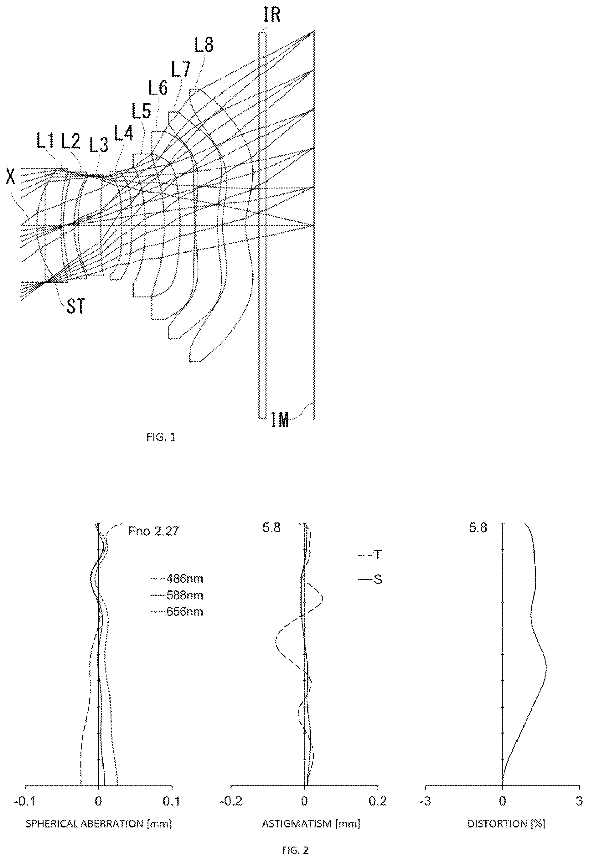
is a sectional view illustrating a schematic configuration of an imaging lens according to Example 1 of the present invention;
is an aberration diagram illustrating spherical aberration, astigmatism, and distortion of the imaging lens in ;
is a sectional view illustrating a schematic configuration of an imaging lens according to Example 2 of the present invention;
is an aberration diagram illustrating spherical aberration, astigmatism, and distortion of the imaging lens in ;
is a sectional view illustrating a schematic configuration of an imaging lens according to Example 3 of the present invention;
is an aberration diagram illustrating spherical aberration, astigmatism, and distortion of the imaging lens in ;
is a sectional view illustrating a schematic configuration of an imaging lens according to Example 4 of the present invention;
is an aberration diagram illustrating spherical aberration, astigmatism, and distortion of the imaging lens in ;
is a sectional view illustrating a schematic configuration of an imaging lens according to Example 5 of the present invention;
is an aberration diagram illustrating spherical aberration, astigmatism, and distortion of the imaging lens in ;
is a sectional view illustrating a schematic configuration of an imaging lens according to Example 6 of the present invention;
is an aberration diagram illustrating spherical aberration, astigmatism, and distortion of the imaging lens in ;
is a sectional view illustrating a schematic configuration of an imaging lens according to Example 7 of the present invention;
is an aberration diagram illustrating spherical aberration, astigmatism, and distortion of the imaging lens in ;
is a sectional view illustrating a schematic configuration of an imaging lens according to Example 8 of the present invention;
is an aberration diagram illustrating spherical aberration, astigmatism, and distortion of the imaging lens in ;
is a sectional view illustrating a schematic configuration of an imaging lens according to Example 9 of the present invention;
is an aberration diagram illustrating spherical aberration, astigmatism, and distortion of the imaging lens in ;
is a sectional view illustrating a schematic configuration of an imaging lens according to Example 10 of the present invention;
is an aberration diagram illustrating spherical aberration, astigmatism, and distortion of the imaging lens in ;
is a sectional view illustrating a schematic configuration of an imaging lens according to Example 11 of the present invention;
is an aberration diagram illustrating spherical aberration, astigmatism, and distortion of the imaging lens in ;
is a sectional view illustrating a schematic configuration of an imaging lens according to Example 12 of the present invention; and
is an aberration diagram illustrating spherical aberration, astigmatism, and distortion of the imaging lens in .
DETAILED DESCRIPTION OF EMBODIMENTS
Referring to the accompanying drawings, an embodiment of the present invention will be described in detail below.
, 3 , 5 , 7 , 9 , 11 , 13 , 15 , 17 , 19 , 21 , and 23 are sectional views illustrating schematic configurations of respective imaging lenses according to Examples 1 through 12 of the present embodiment. Since the imaging lenses in these Examples have the same basic configuration, a description is given here to the lens configuration according to the present embodiment with reference to the illustrative sectional view of Example 1.
As illustrated in , the imaging lens according to the present embodiment includes: in order from an object side to an image side, a first lens L 1 having positive refractive power; a second lens L 2 having negative refractive power; a third lens L 3 having positive refractive power; a fourth lens L 4 having negative refractive power; a fifth lens L 5 ; a sixth lens L 6 having negative refractive power; a seventh lens L 7 having negative refractive power; and an eighth lens L 8 having negative refractive power. Each lens of the first lens L 1 to the eighth lens L 8 is arranged with an air gap. A filter IR is arranged between the eighth lens L 8 and an image plane IM of the image sensor. The filter IR is optional. It should be noted that, unless otherwise specified, refractive power of each lens herein refers to refractive power in a paraxial region.
The first lens L 1 has a shape where a radius of curvature r 2 of an object-side surface and a radius of curvature r 3 of an image-side surface are both positive. The first lens L 1 has a shape of a meniscus lens with a convex surface directed toward the object side in a paraxial region. The shape of the first lens L 1 is not limited to the shape according to Example 1. The first lens L 1 may have a shape to provide positive refractive power. For example, the first lens L 1 may have a shape where the radius of curvature r 2 is positive and the radius of curvature r 3 is negative, that is, a shape providing a biconvex lens in the paraxial region. The first lens L 1 may have a shape where the radius of curvature r 2 of the object-side surface and the radius of curvature r 3 of the image-side surface are both negative and also a shape providing a meniscus lens with a concave surface directed toward the object side in the paraxial region. From the perspective of reduction in the profile of the imaging lens, a shape where the radius of curvature r 2 is positive is preferable.
The second lens L 2 has a shape where a radius of curvature r 4 of an object-side surface and a radius of curvature r 5 of an image-side surface (=R2r) are both positive. The second lens L 2 has a shape providing a meniscus lens with a convex surface directed toward the object side in a paraxial region. The shape of the second lens L 2 is not limited to the shape according to Example 1 and may be a shape to provide negative refractive power. For example, the second lens L 2 may have a shape where the radius of curvature r 4 is negative and the radius of curvature r 5 is positive and also a shape providing a biconcave lens in the paraxial region, or may have a shape providing a meniscus lens with a concave surface directed toward the object side in the paraxial region. From the perspective of reduction in the profile of the imaging lens, it is preferable that the second lens L 2 has a shape where the radius of curvature r 4 is positive, that is, a shape providing a convex object-side surface in the paraxial region.
The third lens L 3 has a shape where a radius of curvature r 6 of an object-side surface (=R3f) and a radius of curvature r 7 of an image-side surface are both positive. The third lens L 3 has a shape providing a meniscus lens with a convex surface directed toward the object side in a paraxial region. The shape of the third lens L 3 is not limited to the shape according to Example 1. The third lens L 3 may have a shape to provide positive refractive power. The third lens L 3 in Example 12 is an example of a shape providing a biconvex lens in the paraxial region. In addition, the third lens L 3 may have other shapes such as a shape providing a meniscus lens with a concave surface directed toward the object side in the paraxial region. Considering reduction in the profile of the imaging lens, it is preferable that the third lens L 3 has a shape where the radius of curvature r 6 is positive.
The fourth lens L 4 has a shape where a radius of curvature r 8 of an object-side surface and a radius of curvature r 9 of an image-side surface are both negative. The fourth lens L 4 has a shape providing a meniscus lens with a concave surface directed toward the object side in a paraxial region. The shape of the fourth lens L 4 is not limited to the shape according to Example 1. The fourth lens L 4 may have a shape to provide negative refractive power. The fourth lens L 4 in each of Examples 2, 3, 6, and 9 is an example of a shape providing a biconcave lens in the paraxial region. Meanwhile, the fourth lens L 4 in each of Examples 4 and 7 is an example of a shape providing a meniscus lens with a convex surface directed toward the object side in the paraxial region.
The fifth lens L 5 has positive refractive power. The refractive power of the fifth lens L 5 is not limited to the positive refractive power. The imaging lens according to each of Examples 8 through 12 is an example of a lens configuration where the fifth lens L 5 has negative refractive power.
The fifth lens L 5 has a shape where a radius of curvature r 10 of an object-side surface and a radius of curvature r 11 of an image-side surface are both negative. The fifth lens L 5 has a shape providing a meniscus lens with a concave surface directed toward the object side in a paraxial region. The shape of the fifth lens L 5 is not limited to the shape according to Example 1. The fifth lens L 5 may have a shape providing a biconcave lens in the paraxial region, a shape providing a biconvex lens in the paraxial region, or a shape providing a meniscus lens with a convex surface directed toward the object side.
The sixth lens L 6 has a shape where a radius of curvature r 12 of an object-side surface (=R6f) and a radius of curvature r 13 of an image-side surface are both negative. The sixth lens L 6 has a shape providing a meniscus lens with a concave surface directed toward the object side in a paraxial region. The shape of the sixth lens L 6 is not limited to the shape according to Example 1 and may be a shape providing a concave object-side surface in the paraxial region. The sixth lens L 6 in Example 11 is an example of a shape providing a biconcave lens in the paraxial region.
The seventh lens L 7 has a shape where a radius of curvature r 14 of an object-side surface and a radius of curvature r 15 of an image-side surface are both positive. The seventh lens L 7 has a shape providing a meniscus lens with a convex surface directed toward the object side in a paraxial region. The shape of the seventh lens L 7 is not limited to the shape according to Example 1. The seventh lens L 7 may have a shape to provide negative refractive power. The seventh lens L 7 may have a shape providing a biconcave lens in the paraxial region or a shape providing a meniscus lens with a concave surface directed toward the object side in the paraxial region.
The eighth lens L 8 has a shape where a radius of curvature r 16 of an object-side surface and a radius of curvature r 17 of an image-side surface are both positive. The eighth lens L 8 has a shape providing a meniscus lens with a convex surface directed toward the object side in a paraxial region. The shape of the eighth lens L 8 is not limited to the shape according to Example 1. The eighth lens L 8 may have a shape to provide negative refractive power. The eighth lens L 8 may have a shape providing a biconcave lens in the paraxial region or a shape providing a meniscus lens with a concave surface directed toward the object side in the paraxial region. It should be noted that, to achieve reduction in the profile of the imaging lens and satisfactory correction of aberrations, the eighth lens L 8 is preferably formed in a shape directing a concave surface toward the image plane side in the paraxial region.
Both surfaces of the seventh lens L 7 and the eighth lens L 8 are aspheric and provided with an inflection point. In this context, the inflection point refers to a point where the positive or negative sign of the curvature on a curve, which is a point where the curving direction of the curve changes on the lens surface. Both surfaces of the seventh lens L 7 and the eighth lens L 8 in the imaging lens according to the present embodiment respectively have an aspheric shape with a pole. Such a shape of the seventh lens L 7 and the eighth lens L 8 allows satisfactory correction of not only axial chromatic aberration but also off-axial chromatic aberration of magnification as well as preferable control of the incident angle of a ray of light emitted from the imaging lens on the image plane IM within the range of CRA. It should be noted that, depending on the expected optical performance and the extent of reduction in the profile of the imaging lens, the eighth lens L 8 may have the other surfaces except the image-side surface formed as aspheric surfaces with no inflection point.
The imaging lens according to the present embodiment satisfies the following conditional expressions (1) through (18): −3.0< f 2/ f 3<−0.2 (1) 1.0< f 3/ f< 7.0 (2) −30.0< f 4/ f 3<−1.0 (3) 1.0< f 34/ f< 6.0 (4) −8.0< f 6/ f<− 1.5 (5) −8.0< f 56/ f<− 1.5 (6) 0.2< f 7/ f 8<8.5 (7) −10.0< f 78/ f<− 2.5 (8) 0.2< f 56/ f 78<6.0 (9) 0.2< R 2 r/R 3 f< 1.0 (10) −4.0< R 6 f/f<− 0.3 (11) 0.2< D 45/ D 34<3.0 (12) 0.2< D 34/ T 3<3.5 (13) 15<vd5<35 (14) 35<vd6<85 (15) 35<vd7<85 (16) 35<vd8<85 (17) 0≤| vd 6 −vd 7|/ vd 7<0.50 (18)
• where • f: a focal length of the entire optical system of the imaging lens, • f2: a focal length of the second lens L 2 , • f3: a focal length of the third lens L 3 , • f4: a focal length of the fourth lens L 4 , • f6: a focal length of the sixth lens L 6 , • f7: a focal length of the seventh lens L 7 , • f8: a focal length of the eighth lens L 8 , • f34: a composite focal length of the third lens L 3 and the fourth lens L 4 , • f56: a composite focal length of the fifth lens L 5 and the sixth lens L 6 , • f78: a composite focal length of the seventh lens L 7 and the eighth lens L 8 , • R2 r : a paraxial curvature radius of an image-side surface of the second lens L 2 , • R3 f : a paraxial curvature radius of an object-side surface of the third lens L 3 , • R6 f : a paraxial curvature radius of an object-side surface of the sixth lens L 6 , • D34: a distance along the optical axis X between the third lens L 3 and the fourth lens L 4 , • D45: a distance along the optical axis X between the fourth lens L 4 and the fifth lens L 5 , • T3: a thickness along the optical axis X of the third lens L 3 , • vd5: an abbe number at the d-line of the fifth lens L 5 , • vd6: an abbe number at the d-line of the sixth lens L 6 , • vd7: an abbe number at the d-line of the seventh lens L 7 , and • vd8: an abbe number at the d line of the eighth lens L 8 .
The imaging lens according to the present embodiment satisfies the total track/diagonal ratio represented by the following conditional expression: 0.5< TTL /(2 ×ih )<1.0 where
TTL: a distance along the optical axis X between the object-side surface of the first lens L 1 and the image plane IM, and
ih: a maximum image height on the image plane IM of the image sensor.
In addition, the imaging lens according to the present embodiment satisfies the following conditional expression: 70°≤2ω
where
ω: a half field of view.
It should be noted that not all the above conditional expressions have to be satisfied and each of the above conditional expressions may be individually satisfied to obtain the operational advantage corresponding to each conditional expression.
The imaging lens according to the present embodiment exhibits more preferred operational advantage by satisfying conditional expressions (1a) through (13a) below: −2.0< f 2/ f 3<−0.5 (1a) 1.0< f 3/ f< 5.0 (2a) −25.0< f 4/ f 3<−1.5 (3a) 1.5< f 34/ f< 5.0 (4a) −7.0< f 6/ f<− 1.5 (5a) −7.0< f 56/ f<− 1.5 (6a) 0.3< f 7/ f 8<6.0 (7a) −8.0< f 78/ f<− 2.8 (8a) 0.3< f 56/ f 78<5.0 (9a) 0.2< R 2 r/R 3 f< 0.8 (10a) −3.5< R 6 f/f<− 0.5 (11a) 0.3< D 45/ D 34<2.5 (12a) 0.4< D 34/ T 3<2.5 (13a).
It should be noted that, as the upper limits and the lower limits of these conditional expressions (1a) through (13a), the upper limits and the lower limits of the corresponding conditional expressions (1) through (13) may be applied to the respective conditional expressions (1a) through (13a).
According to the present embodiment, lens surfaces of the respective lenses are formed as aspheric surfaces. An equation that expresses these aspheric surfaces is as below:
Z = C · H 2 1 + 1 - ( 1 + k ) · C 2 · H 2 + ∑ ( An · H n ) [ Equation 1 ] where
• Z: a distance in the direction of the optical axis, • H: a distance from the optical axis in the direction perpendicular to the optical axis, • C: a paraxial curvature (=1/r, r: paraxial radius of curvature), • k: conic constant, and • An: the nth aspheric coefficient.
Next, Examples of the imaging lens according to the present embodiment will be described. In each table showing basic lens data, f represents a focal length of the entire optical system of the imaging lens, Fno represents an F-number, ω represents a half field of view, ih represents a maximum image height on the image plane IM, and TTL represents a distance along the optical axis between the object-side surface of the first lens L 1 and the image plane IM. Additionally, i represents a surface number counted from the object side, r represents a paraxial radius of curvature, d represents a distance between lens surfaces along the optical axis X, nd represents a refractive index at a reference wavelength of 588 nm, and vd represents an abbe number at the reference wavelength. It should be noted that surfaces indicated by surface numbers i affixed with an asterisk (*) are aspheric surfaces.
EXAMPLE 1
The basic lens data is shown below.
TABLE 1
Example 1
Unitmm
f = 7.762
Fno = 2.27
ω(°) = 36.8
h = 5.8
TTL = 8.27
Surface Data
i r d nd νd
(Object) Infinity Infinity
1 (Stop) Infinity −0.250
2* 2.677 0.722 1.544 56.44 (νd1)
3* 7.699 0.074
4* 3.905 0.320 1.671 19.24 (νd2)
5* 2.792 0.123
6* 5.902 0.685 1.544 56.44 (νd3)
7* 40.728 0.630
8* −18.554 0.300 1.544 56.44 (νd4)
9* −59.570 0.402
10* −10.984 0.576 1.680 18.42 (νd5)
11* −10.294 0.476
12* −6.257 0.447 1.535 55.69 (νd6)
13* −14.587 0.030
14* 7.519 0.656 1.535 55.69 (νd7)
15* 6.595 0.144
16* 2.576 0.706 1.535 55.69 (νd8)
17* 2.124 0.400
18 Infinity 0.210 1.517 64.20
19 Infinity 1.445
Image Plane
ConstituentLens Data
TotalTrack/
Lens StartSurface FocalLength DiagonalRatio
L1 2 7.172 0.71
L2 4 −16.519
L3 6 12.589
L4 8 −49.622
L5 10 180.255
L6 12 −20.877
L7 14 −133.257
L8 16 −49.817
TABLE 2
Aspheric Surface Data
2nd Surface 3rd Surface 4th Surface 5th Surface 6th Surface 7th Surface
k −8.017076E−01 0.000000E+00 −1.154937E+00 −3.514627E+00 0.000000E+00 0.000000E+00
A4 2.593746E−03 −2.240388E−02 −4.528877E−02 −5.006525E−03 2.173294E−02 −4.157946E−03
A6 4.806768E−03 4.618116E−02 5.210962E−02 1.597837E−02 −1.645623E−02 2.886564E−02
A8 −9.832858E−05 −3.557137E−02 −4.239714E−02 −3.359029E−02 3.064603E−02 −5.741224E−02
A10 −6.512751E−03 8.879230E−03 1.405609E−02 5.842074E−02 −2.187957E−02 7.218199E−02
A12 8.255804E−03 8.248670E−03 6.573541E−03 −6.361819E−02 3.287537E−03 −5.142019E−02
A14 −4.949117E−03 −8.514213E−03 −8.382236E−03 4.274666E−02 6.562115E−03 1.909190E−02
A16 1.612586E−03 3.501365E−03 3.498609E−03 −1.699084E−02 −4.804148E−03 −2.151906E−03
A18 −2.737319E−04 −7.278077E−04 −7.034317E−04 3.632830E−03 1.311708E−03 −6.556322E−04
A20 1.863832E−05 6.190769E−05 5.660198E−05 −3.219116E−04 −1.291383E−04 1.631755E−04
8th Surface 9th Surface 10th Surface 11th Surface 12th Surface 13th Surface
k 0.000000E+00 0.000000E+00 −2.754436E+02 −3.061506E+02 −9.073833E+00 −2.776039E+01
A4 −4.424057E−02 −5.313009E−02 −7.107755E−02 −6.911096E−02 2.482841E−02 1.560053E−03
A6 2.109847E−03 1.160181E−02 4.204458E−02 4.950431E−02 9.922034E−04 1.616110E−02
A8 −1.200883E−02 −8.385552E−03 −1.862914E−02 −2.659236E−02 −1.348744E−02 −1.001018E−02
A10 1.454796E−02 −6.810444E−03 −9.921771E−04 4.939301E−03 7.950444E−03 2.417309E−03
A12 −9.419142E−03 1.900212E−02 7.013345E−03 3.375250E−03 −2.659790E−03 −2.287221E−04
A14 1.158208E−03 −1.666973E−02 −4.004416E−03 −2.486479E−03 5.715194E−04 −1.645972E−05
A16 2.098531E−03 7.502666E−03 1.006520E−03 6.956137E−04 −8.093430E−05 6.107306E−06
A18 −1.170867E−03 −1.742694E−03 −1.031579E−04 −9.303634E−05 6.730844E−06 −5.525963E−07
A20 1.899709E−04 1.658218E−04 1.062161E−06 4.909433E−06 −2.700977E−07 1.759887E−08
14th Surface 15th Surface 16th Surface 17th Surface
k −3.397817E−02 6.695992E−02 −1.215761E+00 −5.685665E+00
A4 −2.398610E−02 −2.647156E−03 −1.025805E−01 −5.104882E−02
A6 1.007993E−02 −2.062844E−03 3.078871E−02 1.287009E−02
A8 −6.600300E−03 −1.539249E−03 −7.603569E−03 −2.667577E−03
A10 2.218897E−03 7.343806E−04 1.256651E−03 3.706962E−04
A12 −4.584885E−04 −1.543669E−04 −1.310145E−04 −3.272543E−05
A14 5.899371E−05 1.813754E−05 8.551093E−06 1.818574E−06
A16 −4.487380E−06 −1.208940E−06 −3.398209E−07 −6.209533E−08
A18 1.835556E−07 4.267160E−08 7.546501E−09 1.196357E−09
A20 −3.150692E−09 −6.202587E−10 −7.224922E−11 −9.900442E−12
is an aberration diagram illustrating spherical aberration (mm), astigmatism (mm), and distortion (%) of the imaging lens in Example 1, respectively. The astigmatism diagram and distortion diagram represent the aberrations at the reference wavelength (588 nm). Furthermore, the astigmatism diagram represents a sagittal image surface (S) and a tangential image surface (T), respectively (same in , 6 , 8 , 10 , 12 , 14 , 16 , 18 , 20 , 22 and 24 ). As shown in , the imaging lens according to Example 1 is capable of satisfactorily correcting the aberrations.
EXAMPLE 2
The basic lens data is shown below.
TABLE 3
Example 2
Unitmm
f = 7.747
Fno = 2.29
ω(°) = 36.8
h = 5.8
TTL = 8.01
Surface Data
i r d nd νd
(Object) Infinity Infinity
1 (Stop) Infinity −0.250
2* 2.511 0.683 1.544 56.44 (νd1)
3* 7.217 0.055
4* 3.975 0.272 1.671 19.24 (νd2)
5* 2.794 0.152
6* 5.552 0.689 1.544 56.44 (νd3)
7* 23.348 0.654
8* −46.401 0.300 1.544 56.44 (νd4)
9* 24.932 0.347
10* −12.090 0.477 1.680 18.42 (νd5)
11* −10.152 0.686
12* −6.798 0.297 1.535 55.69 (νd6)
13* −14.616 0.045
14* 7.979 0.502 1.535 55.69 (νd7)
15* 6.357 0.165
16* 2.672 0.740 1.535 55.69 (νd8)
17* 2.210 0.400
18 Infinity 0.210 1.517 64.20
19 Infinity 1.403
Image Plane
ConstituentLens Data
TotalTrack/
Lens StartSurface FocalLength DiagonalRatio
L1 2 6.727 0.69
L2 4 −15.449
L3 6 13.199
L4 8 −29.744
L5 10 84.719
L6 12 −24.084
L7 14 −65.534
L8 16 −54.115
TABLE 4
Aspheric Surface Data
2nd Surface 3rd Surface 4th Surface 5th Surface 6th Surface 7th Surface
k −7.820970E−01 0.000000E+00 −1.161647E+00 −3.479995E+00 0.000000E+00 0.000000E+00
A4 2.761741E−03 −2.240932E−02 −4.531387E−02 −5.016011E−03 2.189403E−02 −4.569668E−03
A6 4.832446E−03 4.610722E−02 5.215648E−02 1.594086E−02 −1.629993E−02 2.886452E−02
A8 −9.983651E−05 −3.559348E−02 −4.238439E−02 −3.361867E−02 3.073025E−02 −5.743567E−02
A10 −6.516398E−03 8.877858E−03 1.405271E−02 5.840492E−02 −2.184327E−02 7.222064E−02
A12 8.253340E−03 8.249083E−03 6.572578E−03 −6.362332E−02 3.292563E−03 −5.140755E−02
A14 −4.950188E−03 −8.514180E−03 −8.382295E−03 4.274399E−02 6.565616E−03 1.909683E−02
A16 1.612172E−03 3.501290E−03 3.498839E−03 −1.699142E−02 −4.802901E−03 −2.146674E−03
A18 −2.738429E−04 −7.278401E−04 −7.032865E−04 3.633012E−03 1.311949E−03 −6.570005E−04
A20 1.860366E−05 6.192342E−05 5.666109E−05 −3.216883E−04 −1.292612E−04 1.624377E−04
8th Surface 9th Surface 10th Surface 11th Surface 12th Surface 13th Surface
k 0.000000E+00 0.000000E+00 −3.224567E+02 −2.232621E+02 −1.089364E+01 −7.569237E+01
A4 −4.541839E−02 −5.090638E−02 −7.178340E−02 −7.004843E−02 2.688175E−02 3.779411E−04
A6 1.936118E−03 1.231084E−02 4.145660E−02 4.948098E−02 1.513091E−03 1.599628E−02
A8 −1.188772E−02 −8.294172E−03 −1.877228E−02 −2.655757E−02 −1.352465E−02 −1.000495E−02
A10 1.451133E−02 −6.781149E−03 −1.012107E−03 4.938382E−03 7.927129E−03 2.418411E−03
A12 −9.417292E−03 1.901274E−02 7.010336E−03 3.374672E−03 −2.658843E−03 −2.284435E−04
A14 1.150105E−03 −1.666813E−02 −4.003939E−03 −2.486644E−03 5.731988E−04 −1.643464E−05
A16 2.092745E−03 7.504127E−03 1.007143E−03 6.955518E−04 −8.052641E−05 6.110219E−06
A18 −1.171872E−03 −1.741870E−03 −1.031442E−04 −9.304922E−05 6.778405E−06 −5.527156E−07
A20 1.914480E−04 1.665266E−04 1.123616E−06 4.906474E−06 −2.676742E−07 1.762515E−08
14th Surface 15th Surface 16th Surface 17th Surface
k −1.224281E−01 −6.317043E−01 −1.209155E+00 −5.675228E+00
A4 −2.397364E−02 −3.001626E−03 −1.025304E−01 −5.185982E−02
A6 1.007614E−02 −2.119971E−03 3.078763E−02 1.289761E−02
A8 −6.602859E−03 −1.537473E−03 −7.603582E−03 −2.666440E−03
A10 2.218656E−03 7.345982E−04 1.256638E−03 3.703515E−04
A12 −4.584762E−04 −1.543648E−04 −1.310153E−04 −3.273643E−05
A14 5.899271E−05 1.813811E−05 8.551059E−06 1.818368E−06
A16 −4.487019E−06 −1.208904E−06 −3.398274E−07 −6.210310E−08
A18 1.835362E−07 4.267432E−08 7.546504E−09 1.196024E−09
A20 −3.148980E−09 −6.198416E−10 −7.224558E−11 −9.896367E−12
As illustrated in , the imaging lens according to Example 2 is also capable of satisfactorily correcting the aberrations.
EXAMPLE 3
The basic lens data is shown below.
TABLE 5
Example 3
Unitmm
f = 7.427
Fno = 2.19
ω(°) = 38.0
h = 5.8
TTL = 8.11
Surface Data
i r d nd νd
(Object) Infinity Infinity
1 (Stop) Infinity −0.250
2* 2.680 0.732 1.544 56.44 (νd1)
3* 7.841 0.058
4* 3.900 0.324 1.671 19.24 (νd2)
5* 2.792 0.130
6* 6.036 0.691 1.544 56.44 (νd3)
7* 47.785 0.647
8* −60.951 0.300 1.544 56.44 (νd4)
9* 46.723 0.418
10* −10.711 0.530 1.671 19.24 (νd5)
11* −10.167 0.354
12* −5.838 0.431 1.567 37.40 (νd6)
13* −12.054 0.030
14* 7.451 0.576 1.535 55.69 (νd7)
15* 6.441 0.119
16* 2.509 0.837 1.535 55.69 (νd8)
17* 2.163 0.400
18 Infinity 0.210 1.517 64.20
19 Infinity 1.393
Image Plane
ConstituentLens Data
TotalTrack/
Lens StartSurface FocalLength DiagonalRatio
L1 2 7.122 0.70
L2 4 −16.602
L3 6 12.615
L4 8 −48.530
L5 10 214.461
L6 12 −20.471
L7 14 −110.831
L8 16 −184.005
TABLE 6
Aspheric Surface Data
2nd Surface 3rd Surface 4th Surface 5th Surface 6th Surface 7th Surface
k −8.030111E−01 0.000000E+00 −1.170305E+00 −3.506672E+00 0.000000E+00 0.000000E+00
A4 2.599278E−03 −2.236793E−02 −4.534383E−02 −4.997563E−03 2.166115E−02 −4.270251E−03
A6 4.760341E−03 4.620835E−02 5.209272E−02 1.600435E−02 −1.646671E−02 2.876159E−02
A8 −1.106083E−04 −3.556406E−02 −4.239653E−02 −3.359356E−02 3.066189E−02 −5.745723E−02
A10 −6.513624E−03 8.880695E−03 1.405426E−02 5.841757E−02 −2.186801E−02 7.220837E−02
A12 8.255943E−03 8.249023E−03 6.573312E−03 −6.361557E−02 3.284167E−03 −5.142352E−02
A14 −4.948968E−03 −8.514119E−03 −8.382103E−03 4.274843E−02 6.560691E−03 1.908585E−02
A16 1.612597E−03 3.501398E−03 3.498811E−03 −1.698982E−02 −4.804733E−03 −2.152158E−03
A18 −2.737177E−04 −7.278063E−04 −7.032897E−04 3.633341E−03 1.311481E−03 −6.572623E−04
A20 1.864203E−05 6.192242E−05 5.666797E−05 −3.218069E−04 −1.290837E−04 1.630877E−04
8th Surface 9th Surface 10th Surface 11th Surface 12th Surface 13th Surface
k 0.000000E+00 0.000000E+00 0.000000E+00 0.000000E+00 −1.132967E+01 −3.512271E+01
A4 −4.394859E−02 −5.341124E−02 −7.073947E−02 −6.927860E−02 2.600643E−02 1.120497E−03
A6 2.272344E−03 1.150191E−02 4.223377E−02 4.944741E−02 1.029657E−03 1.608445E−02
A8 −1.195528E−02 −8.404802E−03 −1.858972E−02 −2.654818E−02 −1.356755E−02 −1.001073E−02
A10 1.450174E−02 −6.807246E−03 −9.875866E−04 4.944461E−03 7.939523E−03 2.418054E−03
A12 −9.405036E−03 1.900504E−02 7.013623E−03 3.375968E−03 −2.658792E−03 −2.284645E−04
A14 1.162871E−03 −1.667232E−02 −4.004198E−03 −2.486411E−03 5.718576E−04 −1.643004E−05
A16 2.095889E−03 7.500984E−03 1.006813E−03 6.956121E−04 −8.096976E−05 6.110545E−06
A18 −1.170797E−03 −1.742991E−03 −1.032361E−04 −9.304121E−05 6.709433E−06 −5.526653E−07
A20 1.893579E−04 1.660678E−04 1.014988E−06 4.907423E−06 −2.675434E−07 1.762091E−08
14th Surface 15th Surface 16th Surface 17th Surface
k −1.295753E+00 3.064777E−02 −1.221343E+00 −4.888969E+00
A4 −2.451333E−02 −2.222579E−03 −1.025689E−01 −5.070537E−02
A6 1.010169E−02 −2.130268E−03 3.079078E−02 1.284881E−02
A8 −6.599748E−03 −1.548673E−03 −7.603430E−03 −2.667916E−03
A10 2.218825E−03 7.334460E−04 1.256657E−03 3.707010E−04
A12 −4.584928E−04 −1.544350E−04 −1.310143E−04 −3.272499E−05
A14 5.899269E−05 1.813360E−05 8.551111E−06 1.818621E−06
A16 −4.487428E−06 −1.209161E−06 −3.398214E−07 −6.209336E−08
A18 1.835576E−07 4.266243E−08 7.546501E−09 1.196480E−09
A20 −3.151221E−09 −6.202198E−10 −7.224319E−11 −9.894041E−12
As illustrated in , the imaging lens according to Example 3 is also capable of satisfactorily correcting the aberrations.
EXAMPLE 4
The basic lens data is shown below.
TABLE 7
Example 4
Unitmm
f = 7.757
Fno = 2.29
ω(°) = 36.8
h = 5.8
TTL = 8.05
Surface Data
i r d nd νd
(Object) Infinity Infinity
1 (Stop) Infinity −0.250
2* 2.555 0.658 1.544 56.44 (νd1)
3* 7.532 0.057
4* 4.032 0.303 1.671 19.24 (νd2)
5* 2.795 0.157
6* 5.524 0.849 1.544 56.44 (νd3)
7* 40.869 0.685
8* 152.780 0.300 1.544 56.44 (νd4)
9* 13.807 0.525
10* −7.327 0.426 1.671 19.24 (νd5)
11* −7.337 0.333
12* −5.287 0.337 1.567 37.40 (νd6)
13* −7.647 0.080
14* 9.073 0.505 1.535 55.69 (νd7)
15* 6.354 0.165
16* 2.687 0.695 1.535 55.69 (νd8)
17* 2.296 0.400
18 Infinity 0.210 1.517 64.20
19 Infinity 1.435
Image Plane
ConstituentLens Data
TotalTrack/
Lens StartSurface FocalLength DiagonalRatio
L1 2 6.785 0.70
L2 4 −15.060
L3 6 11.634
L4 8 −27.901
L5 10 499.828
L6 12 −31.845
L7 14 −42.389
L8 16 −77.589
TABLE 8
Aspheric Surface Data
2nd Surface 3rd Surface 4th Surface 5th Surface 6th Surface 7th Surface
k −8.041223E−01 0.000000E+00 −1.020440E+00 −3.437716E+00 0.000000E+00 0.000000E+00
A4 2.563412E−03 −2.191834E−02 −4.489529E−02 −4.699672E−03 2.152330E−02 −6.459334E−03
A6 4.684377E−03 4.610173E−02 5.231442E−02 1.634454E−02 −1.581784E−02 2.850194E−02
A8 −1.112776E−04 −3.563837E−02 −4.236099E−02 −3.330982E−02 3.078319E−02 −5.766790E−02
A10 −6.527756E−03 8.864263E−03 1.405475E−02 5.849684E−02 −2.189648E−02 7.219855E−02
A12 8.246715E−03 8.242784E−03 6.576950E−03 −6.360834E−02 3.287472E−03 −5.139650E−02
A14 −4.952837E−03 −8.517289E−03 −8.379394E−03 4.273037E−02 6.558575E−03 1.910043E−02
A16 1.611572E−03 3.500286E−03 3.499425E−03 −1.699744E−02 −4.802739E−03 −2.147183E−03
A18 −2.739476E−04 −7.279884E−04 −7.035453E−04 3.632065E−03 1.312553E−03 −6.560082E−04
A20 1.865646E−05 6.200382E−05 5.632902E−05 −3.210952E−04 −1.299120E−04 1.615323E−04
8th Surface 9th Surface 10th Surface 11th Surface 12th Surface 13th Surface
k 0.000000E+00 0.000000E+00 0.000000E+00 0.000000E+00 −7.740153E+00 −2.864142E+01
A4 −5.597766E−02 −5.427419E−02 −6.866487E−02 −7.286291E−02 2.686596E−02 2.624898E−03
A6 1.471152E−03 1.247207E−02 4.213314E−02 4.949878E−02 1.746111E−03 1.597922E−02
A8 −1.206084E−02 −8.370736E−03 −1.880943E−02 −2.649478E−02 −1.375667E−02 −1.002243E−02
A10 1.454392E−02 −6.850737E−03 −1.014487E−03 4.956404E−03 7.908719E−03 2.417796E−03
A12 −9.386875E−03 1.903324E−02 7.027038E−03 3.377294E−03 −2.652726E−03 −2.283976E−04
A14 1.161103E−03 −1.665551E−02 −3.999614E−03 −2.486502E−03 5.737817E−04 −1.641705E−05
A16 2.092218E−03 7.507429E−03 1.006803E−03 6.955289E−04 −8.067453E−05 6.111905E−06
A18 −1.171901E−03 −1.741773E−03 −1.032602E−04 −9.306251E−05 6.670337E−06 −5.526130E−07
A20 1.899303E−04 1.647074E−04 9.727567E−07 4.902462E−06 −2.888289E−07 1.760927E−08
14th Surface 15th Surface 16th Surface 17th Surface
k −3.194244E+00 −2.168468E−01 −1.113069E+00 −5.747594E+00
A4 −2.673414E−02 −2.141577E−03 −1.022483E−01 −5.422458E−02
A6 1.040712E−02 −2.247186E−03 3.078640E−02 1.289548E−02
A8 −6.597095E−03 −1.525199E−03 −7.604045E−03 −2.665669E−03
A10 2.218891E−03 7.348085E−04 1.256612E−03 3.707847E−04
A12 −4.584987E−04 −1.544061E−04 −1.310173E−04 −3.272196E−05
A14 5.898958E−05 1.812692E−05 8.550953E−06 1.818741E−06
A16 −4.487720E−06 −1.211355E−06 −3.398269E−07 −6.208973E−08
A18 1.835325E−07 4.265602E−08 7.546683E−09 1.196642E−09
A20 −3.153753E−09 −6.334678E−10 −7.217240E−11 −9.884904E−12
As illustrated in , the imaging lens according to Example 4 is also capable of satisfactorily correcting the aberrations.
EXAMPLE 5
The basic lens data is shown below.
TABLE 9
Example 5
Unitmm
f = 7.168
Fno = 2.12
ω(°) = 39.0
h = 5.8
TTL = 7.98
Surface Data
i r d nd νd
(Object) Infinity Infinity
1 (Stop) Infinity −0.250
2* 2.687 0.740 1.544 56.44 (νd1)
3* 7.858 0.065
4* 3.880 0.320 1.671 19.24 (νd2)
5* 2.778 0.095
6* 5.896 0.622 1.544 56.44 (νd3)
7* 38.596 0.583
8* −12.339 0.350 1.544 56.44 (νd4)
9* −22.222 0.381
10* −14.557 0.538 1.680 18.42 (νd5)
11* −13.248 0.341
12* −9.565 0.445 1.535 55.69 (νd6)
13* −36.190 0.030
14* 7.074 0.513 1.535 55.69 (νd7)
15* 6.091 0.142
16* 2.436 0.914 1.535 55.69 (νd8)
17* 2.048 0.400
18 Infinity 0.210 1.517 64.20
19 Infinity 1.362
Image Plane
ConstituentLens Data
TotalTrack/
Lens StartSurface FocalLength DiagonalRatio
L1 2 7.139 0.69
L2 4 −16.506
L3 6 12.697
L4 8 −51.604
L5 10 185.828
L6 12 −24.452
L7 14 −100.068
L8 16 −134.358
TABLE 10
Aspheric Surface Data
2nd Surface 3rd Surface 4th Surface 5th Surface 6th Surface 7th Surface
k −8.025610E−01 0.000000E+00 −1.203348E+00 −3.477405E+00 0.000000E+00 0.000000E+00
A4 2.601075E−03 −2.235104E−02 −4.535355E−02 −4.964977E−03 2.166709E−02 −4.240536E−03
A6 4.771387E−03 4.617879E−02 5.209794E−02 1.597315E−02 −1.636778E−02 2.848283E−02
A8 −1.069115E−04 −3.557271E−02 −4.240084E−02 −3.360037E−02 3.066174E−02 −5.755659E−02
A10 −6.511732E−03 8.879870E−03 1.404965E−02 5.842123E−02 −2.187432E−02 7.220839E−02
A12 8.256617E−03 8.248604E−03 6.572177E−03 −6.361378E−02 3.281816E−03 −5.141811E−02
A14 −4.948612E−03 −8.514185E−03 −8.382766E−03 4.274690E−02 6.562018E−03 1.908620E−02
A16 1.612754E−03 3.501415E−03 3.498557E−03 −1.699102E−02 −4.803754E−03 −2.154113E−03
A18 −2.736759E−04 −7.277813E−04 −7.034227E−04 3.632643E−03 1.311783E−03 −6.568411E−04
A20 1.864065E−05 6.192031E−05 5.663934E−05 −3.221088E−04 −1.293102E−04 1.640267E−04
8th Surface 9th Surface 10th Surface 11th Surface 12th Surface 13th Surface
k 0.000000E+00 0.000000E+00 −3.188763E+02 −2.187470E+02 −2.925338E+01 1.304089E+02
A4 −4.355960E−02 −5.358452E−02 −7.137777E−02 −6.899812E−02 2.603867E−02 1.291264E−04
A6 2.820024E−03 1.129669E−02 4.155293E−02 4.949337E−02 4.735942E−04 1.598880E−02
A8 −1.181471E−02 −8.312103E−03 −1.874026E−02 −2.658767E−02 −1.352348E−02 −1.002780E−02
A10 1.451666E−02 −6.749364E−03 −1.010014E−03 4.936271E−03 7.966294E−03 2.418218E−03
A12 −9.419622E−03 1.904158E−02 7.032486E−03 3.374756E−03 −2.655746E−03 −2.285486E−04
A14 1.163226E−03 −1.666921E−02 −3.999041E−03 −2.486487E−03 5.717121E−04 −1.646949E−05
A16 2.099557E−03 7.497979E−03 1.006102E−03 6.956062E−04 −8.101440E−05 6.100186E−06
A18 −1.168498E−03 −1.742969E−03 −1.035134E−04 −9.303892E−05 6.692591E−06 −5.540012E−07
A20 1.901145E−04 1.663862E−04 8.940844E−07 4.910782E−06 −2.723377E−07 1.747859E−08
14th Surface 15th Surface 16th Surface 17th Surface
k 2.252207E−01 8.198137E−01 −1.167918E+00 −4.284976E+00
A4 −2.397665E−02 −2.016763E−03 −1.024014E−01 −5.146347E−02
A6 1.010309E−02 −2.063348E−03 3.079071E−02 1.290621E−02
A8 −6.598016E−03 −1.543275E−03 −7.603352E−03 −2.666390E−03
A10 2.218890E−03 7.341264E−04 1.256655E−03 3.707358E−04
A12 −4.584929E−04 −1.543802E−04 −1.310144E−04 −3.272501E−05
A14 5.899275E−05 1.813716E−05 8.551040E−06 1.818582E−06
A16 −4.487300E−06 −1.208900E−06 −3.398228E−07 −6.209867E−08
A18 1.835352E−07 4.268659E−08 7.546449E−09 1.196029E−09
A20 −3.144673E−09 −6.193376E−10 −7.225654E−11 −9.929291E−12
As illustrated in , the imaging lens according to Example 5 is also capable of satisfactorily correcting the aberrations.
EXAMPLE 6
The basic lens data is shown below.
TABLE 11
Example 6
Unitmm
f = 7.425
Fno = 2.19
ω(°) = 38.0
h = 5.8
TTL = 7.84
Surface Data
i r d nd νd
(Object) Infinity Infinity
1 (Stop) Infinity −0.250
2* 2.561 0.654 1.544 56.44 (νd1)
3* 7.226 0.074
4* 3.896 0.295 1.671 19.24 (νd2)
5* 2.784 0.103
6* 5.506 0.659 1.544 56.44 (νd3)
7* 25.599 0.651
8* −101.878 0.279 1.544 56.44 (νd4)
9* 40.246 0.387
10* −13.810 0.521 1.671 19.24 (νd5)
11* −12.346 0.440
12* −7.225 0.350 1.535 55.69 (νd6)
13* −24.223 0.038
14* 7.743 0.536 1.535 55.69 (νd7)
15* 6.525 0.219
16* 2.571 0.792 1.535 55.69 (νd8)
17* 2.107 0.400
18 Infinity 0.210 1.517 64.20
19 Infinity 1.300
Image Plane
ConstituentLens Data
TotalTrack/
Lens StartSurface FocalLength DiagonalRatio
L1 2 6.941 0.68
L2 4 −16.275
L3 6 12.736
L4 8 −52.952
L5 10 151.939
L6 12 −19.390
L7 14 −91.617
L8 16 −53.888
TABLE 12
Aspheric Surface Data
2nd Surface 3rd Surface 4th Surface 5th Surface 6th Surface 7th Surface
k −7.936548E−01 0.000000E+00 −1.164294E+00 −3.494259E+00 0.000000E+00 0.000000E+00
A4 2.683048E−03 −2.241622E−02 −4.533981E−02 −5.012628E−03 2.182500E−02 −4.277061E−03
A6 4.772636E−03 4.616475E−02 5.211952E−02 1.596016E−02 −1.639283E−02 2.872402E−02
A8 −1.077932E−04 −3.557404E−02 −4.239044E−02 −3.361908E−02 3.069640E−02 −5.750362E−02
A10 −6.515038E−03 8.881206E−03 1.405347E−02 5.840876E−02 −2.185321E−02 7.218803E−02
A12 8.255614E−03 8.250355E−03 6.571925E−03 −6.362194E−02 3.288918E−03 −5.143127E−02
A14 −4.949263E−03 −8.513377E−03 −8.382752E−03 4.274691E−02 6.562625E−03 1.908589E−02
A16 1.612438E−03 3.501667E−03 3.498618E−03 −1.699053E−02 −4.804096E−03 −2.151859E−03
A18 −2.738119E−04 −7.277389E−04 −7.032876E−04 3.633041E−03 1.311665E−03 −6.573147E−04
A20 1.860264E−05 6.189887E−05 5.671023E−05 −3.219280E−04 −1.291016E−04 1.637549E−04
8th Surface 9th Surface 10th Surface 11th Surface 12th Surface 13th Surface
k 0.000000E+00 0.000000E+00 −3.645631E+02 −3.159826E+02 −8.339333E+00 −3.601929E+01
A4 −4.428547E−02 −5.276128E−02 −7.093402E−02 −6.938724E−02 2.469742E−02 8.608807E−04
A6 2.351907E−03 1.170745E−02 4.157516E−02 4.961166E−02 7.022930E−04 1.599218E−02
A8 −1.191259E−02 −8.354675E−03 −1.874316E−02 −2.654795E−02 −1.356951E−02 −1.001951E−02
A10 1.446723E−02 −6.795268E−03 −9.993748E−04 4.942628E−03 7.935928E−03 2.418129E−03
A12 −9.452379E−03 1.900136E−02 7.012824E−03 3.374426E−03 −2.660061E−03 −2.284023E−04
A14 1.141127E−03 −1.667581E−02 −4.000665E−03 −2.486717E−03 5.717765E−04 −1.644290E−05
A16 2.093199E−03 7.498855E−03 1.007465E−03 6.955847E−04 −8.086573E−05 6.109554E−06
A18 −1.168624E−03 −1.742301E−03 −1.033613E−04 −9.304242E−05 6.718821E−06 −5.528661E−07
A20 1.913841E−04 1.674958E−04 7.641013E−07 4.909429E−06 −2.790282E−07 1.755462E−08
14th Surface 15th Surface 16th Surface 17th Surface
k 5.432032E−01 1.525450E−01 −1.162438E+00 −4.871281E+00
A4 −2.374051E−02 −2.629906E−03 −1.023485E−01 −5.272418E−02
A6 1.012759E−02 −2.080741E−03 3.079195E−02 1.285932E−02
A8 −6.597942E−03 −1.540866E−03 −7.603584E−03 −2.666880E−03
A10 2.218897E−03 7.343338E−04 1.256642E−03 3.707189E−04
A12 −4.584821E−04 −1.543681E−04 −1.310155E−04 −3.272549E−05
A14 5.899349E−05 1.813680E−05 8.551019E−06 1.818610E−06
A16 −4.487540E−06 −1.208914E−06 −3.398237E−07 −6.209403E−08
A18 1.835354E−07 4.267867E−08 7.546098E−09 1.196320E−09
A20 −3.154324E−09 −6.194523E−10 −7.225294E−11 −9.897681E−12
As illustrated in , the imaging lens according to Example 6 is also capable of satisfactorily correcting the aberrations.
EXAMPLE 7
The basic lens data is shown below.
TABLE 13
Example 7
Unitmm
f = 7.756
Fno = 2.29
ω(°) = 36.8
h = 5.8
TTL = 8.14
Surface Data
i r d nd νd
(Object) Infinity Infinity
1 (Stop) Infinity −0.373
2* 2.596 0.714 1.544 56.44 (νd1)
3* 8.794 0.043
4* 3.966 0.245 1.671 19.24 (νd2)
5* 2.857 0.200
6* 6.428 0.702 1.544 56.44 (νd3)
7* 15.854 0.639
8* 192.070 0.314 1.544 56.44 (νd4)
9* 74.077 0.973
10* −4.697 0.388 1.671 19.24 (νd5)
11* −4.726 0.020
12* −8.944 0.508 1.535 55.69 (νd6)
13* −56.465 0.128
14* 6.934 0.420 1.535 55.69 (νd7)
15* 5.929 0.186
16* 2.432 0.675 1.535 55.69 (νd8)
17* 2.092 0.400
18 Infinity 0.210 1.517 64.20
19 Infinity 1.443
Image Plane
ConstituentLens Data
TotalTrack/
Lens StartSurface FocalLength DiagonalRatio
L1 2 6.501 0.71
L2 4 −16.706
L3 6 19.352
L4 8 −221.685
L5 10 260.466
L6 12 −19.945
L7 14 −89.592
L8 16 −90.915
TABLE 14
Aspheric Surface Data
2nd Surface 3rd Surface 4th Surface 5th Surface 6th Surface 7th Surface
k −7.658045E−01 0.000000E+00 −1.201557E+00 −3.315639E+00 0.000000E+00 0.000000E+00
A4 2.353069E−03 −2.288233E−02 −4.567659E−02 −5.749449E−03 2.222567E−02 −4.051500E−03
A6 4.767103E−03 4.624566E−02 5.222547E−02 1.629331E−02 −1.551785E−02 2.875390E−02
A8 −9.197408E−05 −3.553739E−02 −4.233673E−02 −3.349957E−02 3.067279E−02 −5.724514E−02
A10 −6.514064E−03 8.881574E−03 1.407241E−02 5.846854E−02 −2.196693E−02 7.227788E−02
A12 8.259139E−03 8.251944E−03 6.574768E−03 −6.361120E−02 3.283271E−03 −5.140536E−02
A14 −4.947162E−03 −8.520976E−03 −8.384777E−03 4.274508E−02 6.577907E−03 1.910179E−02
A16 1.613144E−03 3.502234E−03 3.497582E−03 −1.699231E−02 −4.798606E−03 −2.144599E−03
A18 −2.745124E−04 −7.270678E−04 −7.031838E−04 3.632925E−03 1.312491E−03 −6.645505E−04
A20 1.870825E−05 6.169739E−05 5.652595E−05 −3.220763E−04 −1.306269E−04 1.638799E−04
8th Surface 9th Surface 10th Surface 11th Surface 12th Surface 13th Surface
k 0.000000E+00 0.000000E+00 0.000000E+00 0.000000E+00 0.000000E+00 0.000000E+00
A4 −4.512320E−02 −4.074083E−02 −6.748687E−02 −6.629020E−02 3.044903E−02 −1.593610E−03
A6 3.599379E−03 1.079819E−02 4.211959E−02 4.879809E−02 −2.897480E−04 1.595515E−02
A8 −1.186345E−02 −8.556620E−03 −1.868771E−02 −2.652863E−02 −1.326537E−02 −9.891644E−03
A10 1.428526E−02 −6.724570E−03 −9.491581E−04 4.903957E−03 8.010084E−03 2.415007E−03
A12 −9.405853E−03 1.905919E−02 6.937629E−03 3.376671E−03 −2.662027E−03 −2.291620E−04
A14 1.197627E−03 −1.665003E−02 −4.007217E−03 −2.487819E−03 5.705887E−04 −1.646287E−05
A16 2.117812E−03 7.492959E−03 1.008318E−03 6.952693E−04 −8.141454E−05 6.110629E−06
A18 −1.165998E−03 −1.747217E−03 −1.028962E−04 −9.298546E−05 6.862196E−06 −5.527009E−07
A20 1.843871E−04 1.673737E−04 1.224075E−06 4.921892E−06 −2.415309E−07 1.762356E−08
14th Surface 15th Surface 16th Surface 17th Surface
k 1.630952E−01 0.000000E+00 −1.173598E+00 −4.640814E+00
A4 −2.474052E−02 −3.511985E−03 −1.024218E−01 −5.260800E−02
A6 1.013554E−02 −2.096549E−03 3.080652E−02 1.290854E−02
A8 −6.615503E−03 −1.536760E−03 −7.602873E−03 −2.665275E−03
A10 2.217667E−03 7.343930E−04 1.256609E−03 3.708329E−04
A12 −4.585907E−04 −1.543936E−04 −1.310203E−04 −3.272539E−05
A14 5.898648E−05 1.813877E−05 8.550543E−06 1.818382E−06
A16 −4.487803E−06 −1.208873E−06 −3.398532E−07 −6.211105E−08
A18 1.837032E−07 4.267634E−08 7.546170E−09 1.195999E−09
A20 −3.126008E−09 −6.194083E−10 −7.202225E−11 −9.871533E−12
As illustrated in , the imaging lens according to Example 7 is also capable of satisfactorily correcting the aberrations.
EXAMPLE 8
The basic lens data is shown below.
TABLE 15
Example 8
Unitmm
f = 7.575
Fno = 2.22
ω(°) = 37.4
h = 5.8
TTL = 7.99
Surface Data
i r d nd νd
(Object) Infinity Infinity
1 (Stop) Infinity −0.318
2* 2.626 0.661 1.544 56.44 (νd1)
3* 7.700 0.045
4* 3.865 0.235 1.671 19.24 (νd2)
5* 2.827 0.240
6* 6.055 0.664 1.544 56.44 (νd3)
7* 25.932 0.664
8* −33.767 0.287 1.544 56.44 (νd4)
9* −43.134 0.925
10* −4.531 0.282 1.671 19.24 (νd5)
11* −4.863 0.053
12* −10.640 0.528 1.535 55.69 (νd6)
13* −59.985 0.159
14* 6.760 0.482 1.535 55.69 (νd7)
15* 5.857 0.137
16* 2.471 0.689 1.535 55.69 (νd8)
17* 2.032 0.400
18 Infinity 0.210 1.517 64.20
19 Infinity 1.397
Image Plane
ConstituentLens Data
TotalTrack/
Lens StartSurface FocalLength DiagonalRatio
L1 2 7.000 0.69
L2 4 −17.272
L3 6 14.341
L4 8 −288.713
L5 10 −150.251
L6 12 −24.274
L7 14 −100.763
L8 16 −47.159
TABLE 16
Aspheric Surface Data
2nd Surface 3rd Surface 4th Surface 5th Surface 6th Surface 7th Surface
k −7.894798E−01 0.000000E+00 −1.130651E+00 −3.321557E+00 0.000000E+00 0.000000E+00
A4 2.187424E−03 −2.257754E−02 −4.569648E−02 −5.721946E−03 2.139882E−02 −5.495915E−03
A6 4.836847E−03 4.627302E−02 5.229756E−02 1.612170E−02 −1.649505E−02 2.807159E−02
A8 −1.016307E−04 −3.555768E−02 −4.233699E−02 −3.353139E−02 3.057094E−02 −5.748246E−02
A10 −6.514145E−03 8.868180E−03 1.406286E−02 5.845300E−02 −2.190177E−02 7.225053E−02
A12 8.256604E−03 8.247677E−03 6.570603E−03 −6.361040E−02 3.291001E−03 −5.137620E−02
A14 −4.948544E−03 −8.521359E−03 −8.385067E−03 4.274878E−02 6.578589E−03 1.909750E−02
A16 1.612745E−03 3.502239E−03 3.498121E−03 −1.699102E−02 −4.797860E−03 −2.156879E−03
A18 −2.745124E−04 −7.270678E−04 −7.031838E−04 3.632925E−03 1.312491E−03 −6.645505E−04
A20 1.869606E−05 6.176401E−05 5.677106E−05 −3.216324E−04 −1.304998E−04 1.653595E−04
8th Surface 9th Surface 10th Surface 11th Surface 12th Surface 13th Surface
k 0.000000E+00 0.000000E+00 0.000000E+00 0.000000E+00 0.000000E+00 0.000000E+00
A4 −4.607110E−02 −4.333226E−02 −7.413701E−02 −7.083220E−02 3.044451E−02 −1.857094E−03
A6 2.984651E−03 1.066593E−02 4.251289E−02 4.851381E−02 −6.473490E−04 1.617743E−02
A8 −1.158149E−02 −8.484502E−03 −1.869165E−02 −2.652446E−02 −1.326786E−02 −9.973522E−03
A10 1.430794E−02 −6.694821E−03 −1.115631E−03 4.898533E−03 8.012377E−03 2.421921E−03
A12 −9.411554E−03 1.906652E−02 6.980483E−03 3.375055E−03 −2.662125E−03 −2.288408E−04
A14 1.199273E−03 −1.664668E−02 −4.007749E−03 −2.487609E−03 5.704404E−04 −1.647119E−05
A16 2.121981E−03 7.495849E−03 1.007859E−03 6.954686E−04 −8.132845E−05 6.105713E−06
A18 −1.165998E−03 −1.747217E−03 −1.028962E−04 −9.298546E−05 6.862196E−06 −5.527009E−07
A20 1.851254E−04 1.676287E−04 1.148430E−06 4.929084E−06 −2.428144E−07 1.767464E−08
14th Surface 15th Surface 16th Surface 17th Surface
k −1.655375E−01 0.000000E+00 −1.185903E+00 −4.688516E+00
A4 −2.558509E−02 −2.872437E−03 −1.025527E−01 −5.195292E−02
A6 1.006031E−02 −2.114256E−03 3.080702E−02 1.290140E−02
A8 −6.607526E−03 −1.539477E−03 −7.603152E−03 −2.665344E−03
A10 2.217446E−03 7.344383E−04 1.256615E−03 3.707328E−04
A12 −4.585846E−04 −1.543798E−04 −1.310195E−04 −3.272975E−05
A14 5.898945E−05 1.813688E−05 8.550576E−06 1.818428E−06
A16 −4.487324E−06 −1.208834E−06 −3.398538E−07 −6.210307E−08
A18 1.837032E−07 4.267634E−08 7.546170E−09 1.195999E−09
A20 −3.124579E−09 −6.193678E−10 −7.203295E−11 −9.903240E−12
As illustrated in , the imaging lens according to Example 8 is also capable of satisfactorily correcting the aberrations.
EXAMPLE 9
The basic lens data is shown below.
TABLE 17
Example 9
Unitmm
f = 7.760
Fno = 2.29
ω(°) = 36.8
h = 5.8
TTL = 8.23
Surface Data
i r d nd νd
(Object) Infinity Infinity
1 (Stop) Infinity −0.309
2* 2.593 0.703 1.544 56.44 (νd1)
3* 8.420 0.047
4* 3.846 0.196 1.671 19.24 (νd2)
5* 2.855 0.223
6* 6.842 0.680 1.544 56.44 (νd3)
7* 18.770 0.667
8* −134.649 0.310 1.544 56.44 (νd4)
9* 248.250 0.945
10* −4.544 0.381 1.671 19.24 (νd5)
11* −4.815 0.031
12* −9.971 0.554 1.535 55.69 (νd6)
13* −48.490 0.150
14* 6.719 0.471 1.535 55.69 (νd7)
15* 5.977 0.173
16* 2.427 0.714 1.535 55.69 (νd8)
17* 2.050 0.400
18 Infinity 0.210 1.517 64.20
19 Infinity 1.444
Image Plane
ConstituentLens Data
TotalTrack/
Lens StartSurface FocalLength DiagonalRatio
L1 2 6.601 0.71
L2 4 −17.945
L3 6 19.385
L4 8 −160.297
L5 10 −274.684
L6 12 −23.590
L7 14 −129.925
L8 16 −72.567
TABLE 18
Aspheric Surface Data
2nd Surface 3rd Surface 4th Surface 5th Surface 6th Surface 7th Surface
k −7.808466E−01 0.000000E+00 −1.149231E+00 −3.284993E+00 0.000000E+00 0.000000E+00
A4 2.268785E−03 −2.263194E−02 −4.572512E−02 −5.656326E−03 2.142045E−02 −5.420061E−03
A6 4.865440E−03 4.623581E−02 5.230299E−02 1.612680E−02 −1.647028E−02 2.817144E−02
A8 −9.207060E−05 −3.556409E−02 −4.233979E−02 −3.351617E−02 3.058059E−02 −5.742781E−02
A10 −6.510174E−03 8.867481E−03 1.406070E−02 5.846410E−02 −2.190456E−02 7.227364E−02
A12 8.258374E−03 8.248093E−03 6.569889E−03 −6.360551E−02 3.287302E−03 −5.137278E−02
A14 −4.947868E−03 −8.521107E−03 −8.385122E−03 4.275037E−02 6.577392E−03 1.909878E−02
A16 1.612984E−03 3.502395E−03 3.498130E−03 −1.699065E−02 −4.798226E−03 −2.156538E−03
A18 −2.745124E−04 −7.270678E−04 −7.031838E−04 3.632925E−03 1.312491E−03 −6.645505E−04
A20 1.870803E−05 6.180953E−05 5.676387E−05 −3.216349E−04 −1.304009E−04 1.652672E−04
8th Surface 9th Surface 10th Surface 11th Surface 12th Surface 13th Surface
k 0.000000E+00 0.000000E+00 0.000000E+00 0.000000E+00 0.000000E+00 0.000000E+00
A4 −4.630409E−02 −4.329455E−02 −7.385332E−02 −7.037175E−02 3.119863E−02 −2.239582E−03
A6 2.882554E−03 1.063228E−02 4.286024E−02 4.857793E−02 −3.511791E−04 1.617978E−02
A8 −1.157563E−02 −8.545529E−03 −1.869196E−02 −2.651648E−02 −1.328055E−02 −9.970577E−03
A10 1.431416E−02 −6.731477E−03 −1.123076E−03 4.900806E−03 8.009462E−03 2.420547E−03
A12 −9.420585E−03 1.905496E−02 6.981774E−03 3.375119E−03 −2.662044E−03 −2.290297E−04
A14 1.192411E−03 −1.664952E−02 −4.007486E−03 −2.487764E−03 5.704342E−04 −1.648673E−05
A16 2.123425E−03 7.494330E−03 1.007891E−03 6.954482E−04 −8.133140E−05 6.104999E−06
A18 −1.165998E−03 −1.747217E−03 −1.028962E−04 −9.298546E−05 6.862196E−06 −5.527009E−07
A20 1.852683E−04 1.672191E−04 1.137319E−06 4.928072E−06 −2.434849E−07 1.769115E−08
14th Surface 15th Surface 16th Surface 17th Surface
k −1.298987E−01 0.000000E+00 −1.174751E+00 −4.689865E+00
A4 −2.519423E−02 −3.048836E−03 −1.025133E−01 −5.146822E−02
A6 1.006183E−02 −2.104169E−03 3.080708E−02 1.290951E−02
A8 −6.607845E−03 −1.538836E−03 −7.603074E−03 −2.664862E−03
A10 2.217346E−03 7.344968E−04 1.256614E−03 3.707613E−04
A12 −4.585924E−04 −1.543752E−04 −1.310194E−04 −3.272818E−05
A14 5.898871E−05 1.813698E−05 8.550587E−06 1.818433E−06
A16 −4.487312E−06 −1.208818E−06 −3.398518E−07 −6.210170E−08
A18 1.837032E−07 4.267634E−08 7.546170E−09 1.195999E−09
A20 −3.125685E−09 −6.193604E−10 −7.203090E−11 −9.902963E−12
As illustrated in , the imaging lens according to Example 9 is also capable of satisfactorily correcting the aberrations.
EXAMPLE 10
The basic lens data is shown below.
TABLE 19
Example 10
Unitmm
f = 7.517
Fno = 2.21
ω(°) = 37.7
h = 5.8
TTL = 8.00
Surface Data
i r d nd νd
(Object) Infinity Infinity
1 (Stop) Infinity −0.411
2* 2.596 0.674 1.544 56.44 (νd1)
3* 8.138 0.029
4* 3.814 0.208 1.671 19.24 (νd2)
5* 2.850 0.231
6* 6.565 0.674 1.544 56.44 (νd3)
7* 22.636 0.665
8* −11.425 0.297 1.544 56.44 (νd4)
9* −12.891 0.914
10* −4.518 0.308 1.671 19.24 (νd5)
11* −4.982 0.059
12* −13.974 0.539 1.535 55.69 (νd6)
13* −761.323 0.157
14* 6.682 0.469 1.535 55.69 (νd7)
15* 5.757 0.136
16* 2.450 0.748 1.535 55.69 (νd8)
17* 2.030 0.400
18 Infinity 0.210 1.517 64.20
19 Infinity 1.357
Image Plane
ConstituentLens Data
TotalTrack/
Lens StartSurface FocalLength DiagonalRatio
L1 2 6.715 0.69
L2 4 −18.402
L3 6 16.737
L4 8 −198.711
L5 10 −98.652
L6 12 −26.624
L7 14 −94.372
L8 16 −58.043
TABLE 20
Aspheric Surface Data
2nd Surface 3rd Surface 4th Surface 5th Surface 6th Surface 7th Surface
k −7.800788E−01 0.000000E+00 −1.134256E+00 −3.302852E+00 0.000000E+00 0.000000E+00
A4 2.259756E−03 −2.263685E−02 −4.570544E−02 −5.685774E−03 2.137209E−02 −5.338864E−03
A6 4.859210E−03 4.625199E−02 5.229753E−02 1.611965E−02 −1.648016E−02 2.807761E−02
A8 −9.714802E−05 −3.556105E−02 −4.233803E−02 −3.352994E−02 3.059067E−02 −5.750241E−02
A10 −6.513686E−03 8.867962E−03 1.406180E−02 5.845593E−02 −2.189355E−02 7.224604E−02
A12 8.256606E−03 8.248098E−03 6.570036E−03 −6.360897E−02 3.292229E−03 −5.137687E−02
A14 −4.948526E−03 −8.521161E−03 −8.385051E−03 4.274939E−02 6.579173E−03 1.909982E−02
A16 1.612779E−03 3.502330E−03 3.498186E−03 −1.699089E−02 −4.797610E−03 −2.155563E−03
A18 −2.745124E−04 −7.270678E−04 −7.031838E−04 3.632925E−03 1.312491E−03 −6.645505E−04
A20 1.870537E−05 6.179637E−05 5.678058E−05 −3.216590E−04 −1.303663E−04 1.654653E−04
8th Surface 9th Surface 10th Surface 11th Surface 12th Surface 13th Surface
k 0.000000E+00 0.000000E+00 0.000000E+00 0.000000E+00 0.000000E+00 0.000000E+00
A4 −4.620531E−02 −4.333603E−02 −7.382797E−02 −7.078231E−02 3.063638E−02 −1.950597E−03
A6 2.818861E−03 1.079328E−02 4.278367E−02 4.848025E−02 −6.363666E−04 1.615116E−02
A8 −1.165516E−02 −8.425565E−03 −1.867729E−02 −2.652695E−02 −1.327707E−02 −9.980600E−03
A10 1.429689E−02 −6.693529E−03 −1.116712E−03 4.900903E−03 8.014763E−03 2.421006E−03
A12 −9.408840E−03 1.906165E−02 6.981011E−03 3.375711E−03 −2.661611E−03 −2.289203E−04
A14 1.201335E−03 −1.664916E−02 −4.007819E−03 −2.487501E−03 5.704656E−04 −1.647562E−05
A16 2.129113E−03 7.494122E−03 1.007819E−03 6.955266E−04 −8.133317E−05 6.105786E−06
A18 −1.165998E−03 −1.747217E−03 −1.028962E−04 −9.298546E−05 6.862196E−06 −5.527009E−07
A20 1.841889E−04 1.674656E−04 1.157849E−06 4.932900E−06 −2.434321E−07 1.768444E−08
14th Surface 15th Surface 16th Surface 17th Surface
k −2.314950E−01 0.000000E+00 −1.186460E+00 −4.662067E+00
A4 −2.546252E−02 −2.977599E−03 −1.025518E−01 −5.165063E−02
A6 1.005901E−02 −2.116494E−03 3.080537E−02 1.290557E−02
A8 −6.607160E−03 −1.539776E−03 −7.603131E−03 −2.664945E−03
A10 2.217415E−03 7.344064E−04 1.256611E−03 3.707512E−04
A12 −4.585880E−04 −1.543799E−04 −1.310196E−04 −3.272888E−05
A14 5.898908E−05 1.813676E−05 8.550576E−06 1.818394E−06
A16 −4.487298E−06 −1.208832E−06 −3.398530E−07 −6.210383E−08
A18 1.837032E−07 4.267634E−08 7.546170E−09 1.195999E−09
A20 −3.125032E−09 −6.194602E−10 −7.203284E−11 −9.907364E−12
As illustrated in , the imaging lens according to Example 10 is also capable of satisfactorily correcting the aberrations.
EXAMPLE 11
The basic lens data is shown below.
TABLE 21
Example 11
Unitmm
f = 7.758
Fno = 2.28
ω(°) = 36.8
h = 5.8
TTL = 8.22
Surface Data
i r d nd νd
(Object) Infinity Infinity
1 (Stop) Infinity −0.339
2* 2.636 0.683 1.544 56.44 (νd1)
3* 8.305 0.034
4* 3.816 0.197 1.671 19.24 (νd2)
5* 2.864 0.238
6* 6.762 0.682 1.544 56.44 (νd3)
7* 21.411 0.672
8* −10.505 0.290 1.544 56.44 (νd4)
9* −11.801 0.980
10* −4.491 0.312 1.671 19.24 (νd5)
11* −5.008 0.079
12* −17.985 0.570 1.567 37.40 (νd6)
13* 98.631 0.204
14* 6.990 0.363 1.535 55.69 (νd7)
15* 5.867 0.135
16* 2.413 0.793 1.535 55.69 (νd8)
17* 2.052 0.400
18 Infinity 0.210 1.517 64.20
19 Infinity 1.446
Image Plane
ConstituentLens Data
TotalTrack/
Lens StartSurface FocalLength DiagonalRatio
L1 2 6.802 0.71
L2 4 −18.676
L3 6 17.858
L4 8 −190.733
L5 10 −85.492
L6 12 −26.772
L7 14 −76.952
L8 16 −109.306
TABLE 22
Aspheric Surface Data
2nd Surface 3rd Surface 4th Surface 5th Surface 6th Surface 7th Surface
k −7.775980E−01 0.000000E+00 −1.147998E+00 −3.298930E+00 0.000000E+00 0.000000E+00
A4 2.185268E−03 −2.265599E−02 −4.578381E−02 −5.677689E−03 2.140185E−02 −5.313327E−03
A6 4.865591E−03 4.624044E−02 5.229152E−02 1.613570E−02 −1.646853E−02 2.814234E−02
A8 −9.590235E−05 −3.556958E−02 −4.233878E−02 −3.352610E−02 3.059030E−02 −5.746067E−02
A10 −6.512245E−03 8.866609E−03 1.406023E−02 5.845872E−02 −2.189809E−02 7.225895E−02
A12 8.256127E−03 8.247384E−03 6.570394E−03 −6.360876E−02 3.290830E−03 −5.136715E−02
A14 −4.948077E−03 −8.521179E−03 −8.384952E−03 4.274909E−02 6.578906E−03 1.910205E−02
A16 1.612884E−03 3.502351E−03 3.498195E−03 −1.699103E−02 −4.797666E−03 −2.151978E−03
A18 −2.745124E−04 −7.270678E−04 −7.031838E−04 3.632925E−03 1.312491E−03 −6.645505E−04
A20 1.870686E−05 6.180367E−05 5.677007E−05 −3.216409E−04 −1.303670E−04 1.655125E−04
8th Surface 9th Surface 10th Surface 11th Surface 12th Surface 13th Surface
k 0.000000E+00 0.000000E+00 0.000000E+00 0.000000E+00 0.000000E+00 0.000000E+00
A4 −4.631178E−02 −4.253547E−02 −7.285437E−02 −7.190494E−02 2.849765E−02 −3.795298E−03
A6 2.785551E−03 1.083307E−02 4.285243E−02 4.827327E−02 −7.875861E−04 1.615638E−02
A8 −1.159757E−02 −8.477206E−03 −1.864586E−02 −2.656713E−02 −1.326968E−02 −9.967868E−03
A10 1.431949E−02 −6.722340E−03 −1.123352E−03 4.898994E−03 8.013854E−03 2.421752E−03
A12 −9.405884E−03 1.904733E−02 6.975934E−03 3.375874E−03 −2.661735E−03 −2.289035E−04
A14 1.186187E−03 −1.665407E−02 −4.009112E−03 −2.487436E−03 5.705346E−04 −1.647659E−05
A16 2.120648E−03 7.492883E−03 1.007687E−03 6.955415E−04 −8.132144E−05 6.105560E−06
A18 −1.165998E−03 −1.747217E−03 −1.028962E−04 −9.298546E−05 6.862196E−06 −5.527009E−07
A20 1.846752E−04 1.671788E−04 1.214730E−06 4.934077E−06 −2.439501E−07 1.768615E−08
14th Surface 15th Surface 16th Surface 17th Surface
k −1.598327E+00 0.000000E+00 −1.175311E+00 −4.539581E+00
A4 −2.564487E−02 −3.675565E−03 −1.025329E−01 −5.188153E−02
A6 1.004585E−02 −2.180422E−03 3.080505E−02 1.291241E−02
A8 −6.607013E−03 −1.539932E−03 −7.603191E−03 −2.664224E−03
A10 2.217376E−03 7.345109E−04 1.256611E−03 3.707843E−04
A12 −4.585966E−04 −1.543718E−04 −1.310198E−04 −3.272748E−05
A14 5.898961E−05 1.813695E−05 8.550575E−06 1.818438E−06
A16 −4.487229E−06 −1.208822E−06 −3.398522E−07 −6.210316E−08
A18 1.837032E−07 4.267634E−08 7.546170E−09 1.195999E−09
A20 −3.122527E−09 −6.196761E−10 −7.202173E−11 −9.913037E−12
As illustrated in , the imaging lens according to Example 11 is also capable of satisfactorily correcting the aberrations.
EXAMPLE 12
The basic lens data is shown below.
TABLE 23
Example 12
Unitmm
f = 7.706
Fno = 2.30
ω(°) = 37.0
h = 5.8
TTL = 8.24
Surface Data
i r d nd νd
(Object) Infinity Infinity
1 (Stop) Infinity −0.184
2* 2.706 0.652 1.544 56.44 (νd1)
3* 8.305 0.052
4* 3.844 0.272 1.671 19.24 (νd2)
5* 2.834 0.225
6* 7.190 0.736 1.544 56.44 (νd3)
7* −137.219 0.732
8* −11.621 0.313 1.544 56.44 (νd4)
9* −14.282 0.772
10* −4.224 0.406 1.671 19.24 (νd5)
11* −4.727 0.041
12* −8.272 0.582 1.544 56.44 (νd6)
13* −36.474 0.162
14* 6.663 0.567 1.544 56.44 (νd7)
15* 5.338 0.151
16* 2.391 0.723 1.544 56.44 (νd8)
17* 2.058 0.400
18 Infinity 0.210 1.517 64.20
19 Infinity 1.313
Image Plane
ConstituentLens Data
TotalTrack/
Lens StartSurface FocalLength DiagonalRatio
L1 2 7.081 0.72
L2 4 −18.031
L3 6 12.571
L4 8 −119.494
L5 10 −87.526
L6 12 −19.793
L7 14 −58.091
L8 16 −116.198
TABLE 24
Aspheric Surface Data
2nd Surface 3rd Surface 4th Surface 5th Surface 6th Surface 7th Surface
k −7.841713E−01 0.000000E+00 −1.136885E+00 −3.353886E+00 0.000000E+00 0.000000E+00
A4 2.228902E−03 −2.244810E−02 −4.567716E−02 −5.609548E−03 2.095604E−02 −6.371821E−03
A6 4.731734E−03 4.633305E−02 5.231678E−02 1.606379E−02 −1.661441E−02 2.807266E−02
A8 −1.456398E−04 −3.553930E−02 −4.235582E−02 −3.356719E−02 3.053638E−02 −5.737057E−02
A10 −6.523383E−03 8.873395E−03 1.404717E−02 5.843088E−02 −2.190907E−02 7.230491E−02
A12 8.255761E−03 8.245950E−03 6.573665E−03 −6.361162E−02 3.280234E−03 −5.135865E−02
A14 −4.948596E−03 −8.522983E−03 −8.382043E−03 4.274916E−02 6.574788E−03 1.909932E−02
A16 1.612685E−03 3.501289E−03 3.500411E−03 −1.698970E−02 −4.798968E−03 −2.158957E−03
A18 −2.744342E−04 −7.271088E−04 −7.027808E−04 3.634347E−03 1.313195E−03 −6.653109E−04
A20 1.860151E−05 6.194809E−05 5.693348E−05 −3.202224E−04 −1.304153E−04 1.650578E−04
8th Surface 9th Surface 10th Surface 11th Surface 12th Surface 13th Surface
k 0.000000E+00 0.000000E+00 0.000000E+00 0.000000E+00 4.358582E−01 6.463998E+01
A4 −4.480533E−02 −4.409301E−02 −7.388611E−02 −6.990146E−02 2.999406E−02 −7.509482E−04
A6 3.517213E−03 1.068265E−02 4.288317E−02 4.861301E−02 −9.617270E−04 1.612730E−02
A8 −1.136846E−02 −8.538186E−03 −1.865941E−02 −2.648039E−02 −1.331039E−02 −9.974852E−03
A10 1.438338E−02 −6.739032E−03 −1.117509E−03 4.911187E−03 8.005720E−03 2.420796E−03
A12 −9.390037E−03 1.904429E−02 6.981068E−03 3.378144E−03 −2.661853E−03 −2.289368E−04
A14 1.207884E−03 −1.665412E−02 −4.008637E−03 −2.487154E−03 5.701378E−04 −1.648965E−05
A16 2.126153E−03 7.493250E−03 1.007368E−03 6.954899E−04 −8.144826E−05 6.102138E−06
A18 −1.166759E−03 −1.747067E−03 −1.030868E−04 −9.299849E−05 6.829472E−06 −5.531652E−07
A20 1.850055E−04 1.677334E−04 1.093267E−06 4.920331E−06 −2.586374E−07 1.760849E−08
14th Surface 15th Surface 16th Surface 17th Surface
k 1.230306E+00 1.596085E−02 −1.156009E+00 −4.969747E+00
A4 −2.552896E−02 −2.913601E−03 −1.024328E−01 −5.179786E−02
A6 1.022573E−02 −2.167818E−03 3.081518E−02 1.294750E−02
A8 −6.600783E−03 −1.541273E−03 −7.602775E−03 −2.662510E−03
A10 2.217277E−03 7.344659E−04 1.256615E−03 3.708592E−04
A12 −4.586461E−04 −1.543831E−04 −1.310195E−04 −3.272535E−05
A14 5.898244E−05 1.813675E−05 8.550551E−06 1.818334E−06
A16 −4.487977E−06 −1.208855E−06 −3.398556E−07 −6.211031E−08
A18 1.837534E−07 4.267235E−08 7.546205E−09 1.196046E−09
A20 −3.137912E−09 −6.188673E−10 −7.204816E−11 −9.947908E−12
As illustrated in , the imaging lens according to Example 12 is also capable of satisfactorily correcting the aberrations.
As described above, the imaging lens according to the present embodiment is capable of allows satisfactorily correcting aberrations in spite of the small total track/diagonal ratio. The values corresponding to the conditional expressions (1) through (18) in Examples according to the present embodiment (corresponding values for conditional expressions) are listed below.
TABLE 25
Corresponding Value
for Conditional Expression Example 1 Example 2 Example 3 Example 4 Example 5 Example 6
(1) f2/f3 −1.31 −1.17 −1.32 −1.29 −1.32 −1.29
(2) f3/f 1.622 1.704 1.648 1.500 1.656 1.677
(3) f4/f3 −3.942 −2.254 −3.576 −2.398 −4.311 −4.212
(4) f34/4 2.113 2.831 2.207 2.352 2.109 2.137
(5) f6/f −2.690 −3.109 −2.495 −4.105 −2.494 −2.463
(6) f56/f −2.975 −4.284 −2.734 −4.276 −2.697 −2.713
(7) f7/f8 2.675 1.211 0.498 0.546 2.045 1.991
(8) f78/f −4.625 −3.671 −5.975 −3.325 −4.560 −3.863
(9) f56/f78 0.643 1.167 0.458 1.286 0.591 0.702
(10) R2r/R3f 0.473 0.503 0.459 0.506 0.469 0.481
(11) R6f/f −0.806 −0.878 −0.719 −0.682 −0.905 −0.885
(12) D45/D34 0.638 0.531 0.679 0.766 0.649 0.640
(13) D34/T3 0.920 0.949 0.942 0.807 0.928 0.963
(14) νd5 18.42 18.42 19.24 19.24 18.42 19.24
(15) νd6 55.69 55.69 37.40 37.40 55.69 55.69
(16) νd7 55.69 55.69 55.69 55.69 55.69 55.69
(17) νd8 55.69 55.69 55.69 55.69 55.69 55.69
(18) |νd6 − νd7 |/ νd7 0.00 0.00 0.33 0.33 0.00 0.00
Corresponding Value
for Conditional Expression Example 7 Example 8 Example 9 Example 10 Example 11 Example 12
(1) f2/f3 −0.86 −1.19 −0.93 −1.06 −1.05 −1.43
(2) f3/f 2.495 1.864 2.498 2.236 2.302 1.631
(3) f4/f3 −11.455 −20.060 −8.269 −11.457 −10.681 −9.506
(4) f34/4 2.711 1.959 2.814 2.454 2.545 1.819
(5) f6/f −2.572 −3.051 −3.040 −3.381 −3.451 −2.569
(6) f56/f −2.688 −2.471 −2.716 −2.607 −2.570 −2.032
(7) f7/f8 0.985 1.413 1.790 1.193 0.704 0.500
(8) f78/f −5.556 −5.024 −5.833 −5.468 −5.428 −4.682
(9) f56/f78 0.484 0.492 0.466 0.477 0.473 0.434
(10) R2r/R3f 0.444 0.462 0.417 0.428 0.424 0.394
(11) R6f/f −1.153 −1.255 −1.285 −1.554 −2.318 −1.073
(12) D45/D34 1.523 1.415 1.417 1.430 1.458 1.055
(13) D34/T3 0.910 0.990 0.981 0.982 0.985 0.995
(14) νd5 19.24 19.24 19.24 19.24 19.24 19.24
(15) νd6 55.69 55.69 55.69 55.69 37.40 56.44
(16) νd7 55.69 55.69 55.69 55.69 55.69 56.44
(17) νd8 55.69 55.69 55.69 55.69 55.69 56.44
(18) |νd6 − νd7 |/ νd7 0.00 0.00 0.00 0.00 0.33 0.00
Therefore, when the imaging lens according to the above embodiment is applied to imaging optical systems of cameras built in portable information devices, such as smartphones, cellular phones, and portable information terminals, video game consoles, home appliances, automobiles, and the like, it is possible to achieve both greater functionality and miniaturization of the cameras.
The present invention is applicable to an imaging lens assembled into relatively small-sized cameras to be built in portable information devices, such as smartphones, medical devices, video game consoles, home appliances, automobiles, and the like.
DESCRIPTION OF REFERENCE NUMERALS
•
• X: optical axis • ST: aperture stop • L 1 : first lens • L 2 : second lens • L 3 : third lens • L 4 : fourth lens • L 5 : fifth lens • L 6 : sixth lens • L 7 : seventh lens • L 8 : eighth lens • IR: filter • IM: image plane
Figures (12)
Citations
This patent cites (4)
- US11662555
- US2019/0310448
- US2020/0174227
- US111007631