Optical System, Optical Apparatus, and Method for Manufacturing Optical System
Abstract
An optical system and an optical apparatus that have favorable imaging performance and a method for manufacturing the optical system are provided. An optical system OL includes, sequentially from an object side, a front group G 1 having positive refractive power and a focusing group G 2 that performs focusing by moving in an optical axis direction, the front group G 1 includes, sequentially from the object side, a first lens L 11 , a second lens L 12 , and a third lens L 13 , and the optical system OL satisfies a condition expressed by an expression below, 0.10< D 23/ f 1<0.75 in the expression, f1: focal length of the front group G 1 , and D23: distance on an optical axis between the second lens L 12 and the third lens L 13.
Claims (23)
1. An optical system comprising, sequentially from an object side: a front group having positive refractive power; and a focusing group that performs focusing by moving in an optical axis direction, wherein the front group includes, sequentially from the object side, a front-group A lens group and a front-group B lens group between which a largest air space on the optical axis in the front group is interposed, the front-group A lens group consists of, sequentially from the object side: a first lens, and a second lens, the front-group B lens group includes: a third lens, the first lens has positive refractive power, the second lens has positive refractive power, the first lens, the second lens, and the third lens being disposed sequentially in this order from the object side, and the following conditional expressions are satisfied: 0.10< D 23/ f 1<0.65 −0.50< f 1/ f 1 B< 0.00 when f 1 B< 0.00 0.00< f 1/ f 1 B< 3.00 when f 1 B> 0.00 where f1: focal length of the front group, D23: distance on an optical axis between the second lens and the third lens, and f1B: focal length of the front-group B lens group.
23. A method for manufacturing an optical system including, sequentially from an object side, a front group having positive refractive power and a focusing group that performs focusing by moving in an optical axis direction, the method for manufacturing the optical system comprising: disposing in the front group, sequentially from the object side, a front-group A lens group and a front-group B lens group, between which a largest air space on the optical axis in the front group is interposed, disposing, sequentially from the object side, a first lens, and a second lens in the front-group A lens group, and a third lens in the front-group B lens group, wherein the front-group A lens group consists of the first lens and the second lens, the first lens, the second lens, and the third lens being disposed sequentially in this order from the object side, the first lens having positive refractive power, and the second lens having positive refractive power; and disposing the lenses so that the following conditional expressions are satisfied: 0.10 <D 23 /f 1<0.65 −0.50 <f 1 /f 1 B< 0.00 when f 1 B< 0.00 0.00 <f 1 /f 1 B< 3.00 when f 1 B> 0.00 where f1: focal length of the front group, D23: distance on the optical axis between the second lens and the third lens, and f1B: focal length of the front-group B lens group.
Show 21 dependent claims
2. The optical system according to claim 1 , wherein the following conditional expression is satisfied: 1.00<fL1/ f 1<6.00 where fL1: focal length of the first lens.
3. The optical system according to claim 1 , wherein the following conditional expression is satisfied: 75.00<ν L 2<100.00 where νL2: Abbe number of a medium of the second lens at a d line.
4. The optical system according to claim 1 , wherein the following conditional expression is satisfied: 75.00< νL 3<100.00 where νL3: Abbe number of a medium of the third lens at a d line.
5. The optical system according to claim 1 , wherein the following conditional expression is satisfied: 0.001 <TL 1/fL1<0.025 where fL1: focal length of the first lens, and TL1: thickness of the first lens on the optical axis.
6. The optical system according to claim 1 , wherein the following conditional expression is satisfied: 0.010 <TL 2/fL2<0.035 where fL2: focal length of the second lens, and TL2: thickness of the second lens on the optical axis.
7. The optical system according to claim 1 , wherein the following conditional expression is satisfied: −1.00< f/f 1 B< 0.00 when f 1 B< 0.00 0.00< f/f 1 B< 5.00 when f 1 B> 0.00 where f: overall focal length of the optical system in a state of focusing at infinity.
8. The optical system according to claim 1 , wherein the following conditional expression is satisfied: 0.50 <f 1 A/f< 1.50 where f: overall focal length of the optical system in a state of focusing at infinity, and f1A: focal length of the front-group A lens group.
9. The optical system according to claim 1 , wherein the following conditional expression is satisfied: 0.50 <f 1 A/f 1<2.50 where f1A: focal length of the front-group A lens group.
10. The optical system according to claim 1 , wherein the following conditional expression is satisfied: −0.50 <f 1 A/f 1 B< 0.00 when f 1 B< 0.00 0.00 <f 1 A/f 1 B< 3.00 when f 1 B> 0.00 where f1A: focal length of the front-group A lens group.
11. The optical system according to claim 1 , wherein the front group includes at least one negative lens that satisfies the following conditional expressions: −0.015<θ gFn− 0.6558+0.001982 ×νdn< 0.000 νdn<50.00 where θgFn: partial dispersion ratio of a medium of the negative lens, and νdn: Abbe number of the medium of the negative lens at a d line.
12. The optical system according to claim 1 , wherein the front group includes at least one positive lens that satisfies the following conditional expressions: 20.00 <νdp< 30.00 1.830 <ndp+ 0.01425 ×νdp< 2.120 0.7020<θ gFp+ 0.00316×ν dp where νdp: Abbe number of a medium of the positive lens at a d line, ndp: refractive index of the medium of the positive lens at the d line, and θgFp: partial dispersion ratio of the medium of the positive lens.
13. The optical system according to claim 1 , wherein the following conditional expression is satisfied: −0.60 <f 2 /f< 0.00 when f 2<0.00 0.00 <f 2 /f< 0.60 when f 2>0.00 where f: overall focal length of the optical system in a state of focusing at infinity, and f2: focal length of the focusing group.
14. The optical system according to claim 1 , further comprising a rear group on an image side of the focusing group.
15. The optical system according to claim 1 , further comprising an aperture stop on an image side of the focusing group.
16. The optical system according to claim 1 , further comprising a rear group on an image side of the focusing group, wherein at least part of the rear group is movable so as to have a displacement component in a direction perpendicular to the optical axis.
17. The optical system according to claim 1 , further comprising a rear group on an image side of the focusing group, wherein the rear group includes, sequentially from the object side, a rear-group A lens group and a rear-group B lens group between which a largest air space on the optical axis in the rear group is interposed.
18. The optical system according to claim 1 , further comprising a rear group on an image side of the focusing group, wherein the rear group includes, sequentially from the object side, a rear-group A lens group and a rear-group B lens group between which a largest air space on the optical axis in the rear group is interposed, and the following conditional expression is satisfied: −4.00 <f 3 /f 3 A< 0.00 when f 3 A< 0.00 0.00 <f 3 /f 3 A< 7.00 when f 3 A> 0.00 where f3: focal length of the rear group, and f3A: focal length of the rear-group A lens group.
19. The optical system according to claim 1 , further comprising a rear group on an image side of the focusing group, wherein the rear group includes, sequentially from the object side, a rear-group A lens group and a rear-group B lens group between which a largest air space on the optical axis in the rear group is interposed, and the following conditional expression is satisfied: −3.00 <f 3 /f 3 B< 0.00 when f 3 B< 0.00 0.00 <f 3 /f 3 B< 5.00 when f 3 B> 0.00 where f3: focal length of the rear group, and f3B: focal length of the rear-group B lens group.
20. The optical system according to claim 1 , wherein the following conditional expression is satisfied: 0.70<TL/ f< 1.10 where f: overall focal length of the optical system in a state of focusing at infinity, and TL: total length of the optical system in a state of focusing at infinity.
21. The optical system according to claim 1 , wherein the following conditional expression is satisfied: 0.02<(− fr )/ f< 0.35 where f: overall focal length of the optical system in a state of focusing at infinity, and fr: focal length of a lens having negative refractive power and disposed closest to an image side.
22. An optical apparatus comprising the optical system according to claim 1 .
Full Description
Show full text →
TECHNICAL FIELD
The present invention relates to an optical system, an optical apparatus, and a method for manufacturing the optical system.
BACKGROUND ART
Conventionally, an optical system having a small size and a light weight has been desired (see Patent Literature 1, for example). However, further improvement of optical performance is required for an optical system disclosed in Patent Literature 1.
CITATION LIST
Patent Literature
•
• Patent Literature 1: Japanese Patent Laid-open No. 2011-085788
SUMMARY OF INVENTION
An optical system according to a first aspect of the present invention includes: sequentially from an object side, a front group having positive refractive power; and a focusing group that performs focusing by moving in an optical axis direction, the front group includes, sequentially from the object side, a first lens, a second lens, and a third lens, and the optical system satisfies a condition expressed by an expression below, 0.10< D 23/ f 1<0.75
•
• in the expression, • f1: focal length of the front group, and • D23: distance on an optical axis between the second lens and the third lens.
A method for manufacturing the optical system according to the first aspect of the present invention is a method for manufacturing an optical system including, sequentially from an object side, a front group having positive refractive power and a focusing group that performs focusing by moving in an optical axis direction, the method for manufacturing the optical system including: disposing, sequentially from the object side, a first lens, a second lens, and a third lens in the front group; and disposing the lenses so that a condition expressed by an expression below is satisfied, 0.10< D 23/ f 1<0.75
•
• in the expression, • f1: focal length of the front group, and • D23: distance on the optical axis between the second lens and the third lens.
BRIEF DESCRIPTION OF DRAWINGS
is a cross-sectional view showing a lens configuration of an optical system according to a first example in a state of focusing at infinity.
shows a variety of aberration diagrams of the optical system according to the first example: (a) shows focusing upon an infinite distance object; and (b) shows focusing upon a close distance object.
is a cross-sectional view showing a lens configuration of an optical system according to a second example in a state of focusing at infinity.
shows a variety of aberration diagrams of the optical system according to the second example: (a) shows focusing upon an infinite distance object; and (b) shows focusing upon a close distance object.
is a cross-sectional view showing a lens configuration of an optical system according to a third example in a state of focusing at infinity.
shows a variety of aberration diagrams of the optical system according to the third example: (a) shows focusing upon an infinite distance object; and (b) shows focusing upon a close distance object.
is a cross-sectional view showing a lens configuration of an optical system according to a fourth example in a state of focusing at infinity.
shows a variety of aberration diagrams of the optical system according to the fourth example: (a) shows focusing upon an infinite distance object; and (b) shows focusing upon a close distance object.
is a cross-sectional view showing a lens configuration of an optical system according to a fifth example in a state of focusing at infinity.
shows a variety of aberration diagrams of the optical system according to the fifth example: (a) shows focusing upon an infinite distance object; and (b) shows focusing upon a close distance object.
is a cross-sectional view showing a lens configuration of an optical system according to a sixth example in a state of focusing at infinity.
shows a variety of aberration diagrams of the optical system according to the sixth example: (a) shows focusing upon an infinite distance object; and (b) shows focusing upon a close distance object.
is a cross-sectional view showing a lens configuration of an optical system according to a seventh example in a state of focusing at infinity.
shows a variety of aberration diagrams of the optical system according to the seventh example: (a) shows focusing upon an infinite distance object; and (b) shows focusing upon a close distance object.
is a cross-sectional view of a camera on which an above-described optical system is mounted.
is a flowchart for description of a method for manufacturing the above-described optical system.
DESCRIPTION OF EMBODIMENTS
Preferable embodiments will be described below with reference to the drawings.
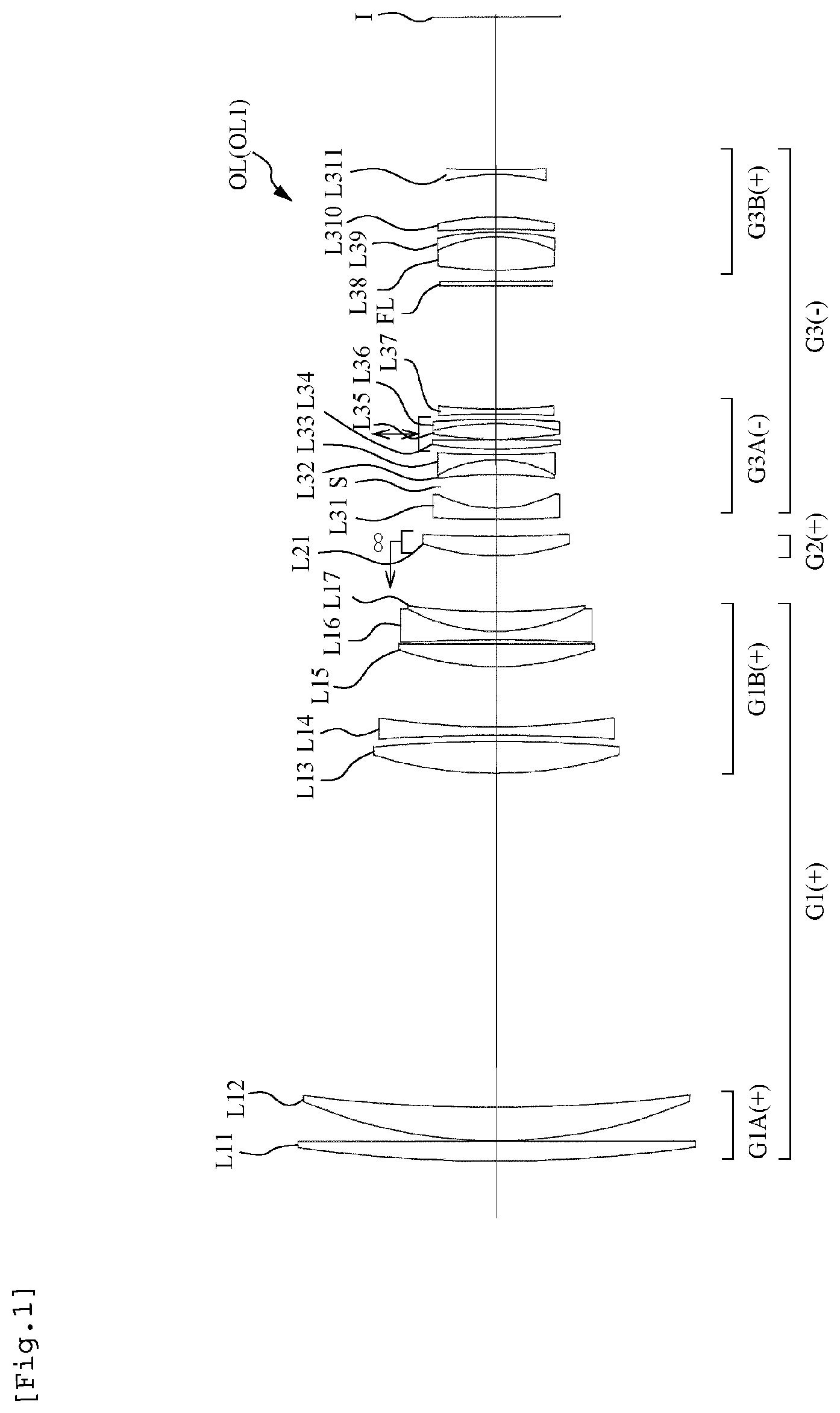
As shown in , an optical system OL according to the present embodiment includes, sequentially from an object side, a front group G 1 having positive refractive power and a focusing group G 2 that performs focusing by moving in an optical axis direction. The front group G 1 includes, sequentially from the object side, a first lens L 11 having positive refractive power, a second lens L 12 having positive refractive power, and a third lens L 13 . With this configuration, it is possible to favorably correct aberration of the optical system OL and achieve size reduction and weight reduction.
Moreover, the optical system OL according to the present embodiment desirably satisfies Conditional Expression (1) shown below. 0.10< D 23/ f 1<0.75 (1)
In the expression,
•
• f1: focal length of the front group G 1 , and • D23: distance on the optical axis between the second lens L 12 and the third lens L 13 .
Conditional Expression (1) defines the ratio of the distance on the optical axis between the second lens L 12 and the third lens L 13 included in the front group G 1 relative to the focal length of the front group G 1 . When Conditional Expression (1) is satisfied, it is possible to favorably correct a variety of aberrations such as coma aberration, longitudinal chromatic aberration, and lateral chromatic aberration, in particular. When the lower limit value of Conditional Expression (1) is exceeded, the distance on the optical axis between the second lens L 12 and the third lens L 13 is too long, which makes it difficult to achieve aberration correction. Meanwhile, it is possible to secure the advantageous effect of the present embodiment more surely by setting the lower limit value of Conditional Expression (1) to 0.11. Further, in order to secure the advantageous effect of the present embodiment more surely, it is preferable to set the lower limit value of Conditional Expression (1) to 0.13, 0.15, 0.16, and more preferable to 0.17. Moreover, when the upper limit value of Conditional Expression (1) is exceeded, the distance on the optical axis between the second lens L 12 and the third lens L 13 is too short, which makes it difficult to achieve weight reduction. Meanwhile, it is possible to secure the advantageous effect of the present embodiment more surely by setting the upper limit value of Conditional Expression (1) to 0.73. Further, in order to secure the advantageous effect of the present embodiment more surely, it is preferable to set the upper limit value of Conditional Expression (1) to 0.70, 0.65, 0.60, 0.55, 0.50, 0.48, 0.45, 0.43, and more preferable to 0.41.
Moreover, the optical system OL according to the present embodiment desirably satisfies Conditional Expression (2) shown below. 1.00<fL1/ f 1<6.00 (2)
In the expression,
•
• f1: focal length of the front group G 1 , and • fL1: focal length of the first lens L 11 .
Conditional Expression (2) defines the ratio of the focal length of the first lens L 11 included in the front group G 1 relative to the focal length of the front group G 1 . When Conditional Expression (2) is satisfied, the first lens L 11 can have sufficient refractive power (power), and thus it is possible to favorably correct a variety of aberrations such as spherical aberration and coma aberration, in particular, by decreasing the refractive power (power) of the second lens L 12 . When the lower limit value of Conditional Expression (2) is exceeded, the refractive power (power) of the first lens L 11 is too strong, which makes it difficult to achieve aberration correction. Meanwhile, it is possible to secure the advantageous effect of the present embodiment more surely by setting the lower limit value of Conditional Expression (2) to 1.05. Further, in order to secure the advantageous effect of the present embodiment more surely, it is preferable to set the lower limit value of Conditional Expression (2) to 1.10, 1.15, 1.20, 1.25, 1.30, 1.33, and more preferable to 1.35. Moreover, when the upper limit value of Conditional Expression (2) is exceeded, the refractive power (power) of the first lens L 11 is too weak, which makes it difficult to achieve aberration correction. Meanwhile, it is possible to secure the advantageous effect of the present embodiment more surely by setting the upper limit value of Conditional Expression (2) to 5.80. Further, in order to secure the advantageous effect of the present embodiment more surely, it is preferable to set the upper limit value of Conditional Expression (2) to 5.50, 5.00, 4.50, 4.00, 3.80, and more preferable to 3.50.
Moreover, the optical system OL according to the present embodiment desirably satisfies Conditional Expression (3) shown below. 75.00<ν L 2<100.00 (3)
In the expression,
•
• νL2: Abbe number of the medium of the second lens L 12 at a d line.
Conditional Expression (3) defines the Abbe number of the medium of the second lens L 12 included in the front group G 1 at the d line. When Conditional Expression (3) is satisfied, it is possible to favorably correct chromatic aberrations of the entire optical system OL, such as longitudinal chromatic aberration and lateral chromatic aberration, in particular. When the lower limit value of Conditional Expression (3) is exceeded, dispersion of the second lens L 12 is too large, which makes it difficult to achieve chromatic aberration correction. Meanwhile, it is possible to secure the advantageous effect of the present embodiment more surely by setting the lower limit value of Conditional Expression (3) to 78.00. Further, in order to secure the advantageous effect of the present embodiment more surely, it is preferable to set the lower limit value of Conditional Expression (3) to 80.00, 85.00, 88.00, 90.00, 92.00, and more preferable to 95.00. Moreover, when the upper limit value of Conditional Expression (3) is exceeded, dispersion of the second lens L 12 is too small, which makes it difficult to achieve chromatic aberration correction. Meanwhile, it is possible to secure the advantageous effect of the present embodiment by setting the upper limit value of Conditional Expression (3) to 98.00. Further, in order to secure the advantageous effect of the present embodiment, it is preferable to set the upper limit value of Conditional Expression (3) to 97.00.
Moreover, the optical system OL according to the present embodiment desirably satisfies Conditional Expression (4) shown below. 75.00<ν L 3<100.00 (4)
In the expression,
•
• νL3: Abbe number of the medium of the third lens L 13 at the d line.
Conditional Expression (4) defines the Abbe number of the medium of the third lens L 13 included in the front group G 1 at the d line. When Conditional Expression (4) is satisfied, it is possible to favorably correct chromatic aberrations of the entire optical system OL, such as longitudinal chromatic aberration and lateral chromatic aberration, in particular. When the lower limit value of Conditional Expression (4) is exceeded, dispersion of the third lens L 13 is too large, which makes it difficult to achieve chromatic aberration correction. Meanwhile, it is possible to secure the advantageous effect of the present embodiment more surely by setting the lower limit value of Conditional Expression (4) to 78.00. Further, in order to secure the advantageous effect of the present embodiment more surely, it is preferable to set the lower limit value of Conditional Expression (4) to 80.00, 85.00, 88.00, 90.00, 92.00, and more preferable to 95.00. Moreover, when the upper limit value of Conditional Expression (4) is exceeded, dispersion of the third lens L 13 is too small, which makes it difficult to achieve chromatic aberration correction. Meanwhile, it is possible to secure the advantageous effect of the present embodiment by setting the upper limit value of Conditional Expression (4) to 98.00. Further, in order to secure the advantageous effect of the present embodiment, it is preferable to set the upper limit value of Conditional Expression (4) to 97.00.
Moreover, the optical system OL according to the present embodiment desirably satisfies Conditional Expression (5) shown below. 0.001< TL 1/fL1<0.025 (5)
In the expression,
•
• fL1: focal length of the first lens L 11 , and • TL1: thickness of the first lens L 11 on the optical axis.
Conditional Expression (5) defines the ratio of the thickness of the first lens L 11 included in the front group G 1 on the optical axis relative to the focal length thereof. When Conditional Expression (5) is satisfied, it is possible to achieve weight reduction of the optical system OL and also favorably correct a variety of aberrations such as spherical aberration and coma aberration, in particular. When the lower limit value of Conditional Expression (5) is exceeded, the refractive power (power) of the first lens L 11 is weak, and thus it is difficult to achieve aberration correction when the thickness of the first lens L 11 is reduced. Meanwhile, it is possible to secure the advantageous effect of the present embodiment more surely by setting the lower limit value of Conditional Expression (5) to 0.002. Further, in order to secure the advantageous effect of the present embodiment more surely, it is preferable to set the lower limit value of Conditional Expression (5) to 0.003, 0.004, 0.005, and more preferable to 0.006. Moreover, when the upper limit value of Conditional Expression (5) is exceeded, the refractive power (power) of the first lens L 11 is strong, and thus it is difficult to achieve aberration correction when the thickness of the first lens L 11 is increased. Meanwhile, it is possible to secure the advantageous effect of the present embodiment by setting the upper limit value of Conditional Expression (5) to 0.023. Further, in order to secure the advantageous effect of the present embodiment more surely, it is preferable to set the upper limit value of Conditional Expression (5) to 0.020, 0.019, 0.018, 0.017, 0.016, and more preferable to 0.015.
Moreover, the optical system OL according to the present embodiment desirably satisfies Conditional Expression (6) shown below. 0.010< TL 2/fL2<0.035 (6)
In the expression,
•
• fL2: focal length of the second lens L 12 , and • TL2: thickness of the second lens L 12 on the optical axis.
Conditional Expression (6) defines the ratio of the thickness of the second lens L 12 included in the front group G 1 on the optical axis relative to the focal length thereof. When Conditional Expression (6) is satisfied, it is possible to achieve weight reduction of the optical system OL and also favorably correct a variety of aberrations such as spherical aberration and coma aberration, in particular. When the lower limit value of Conditional Expression (6) is exceeded, the refractive power (power) of the second lens L 12 is weak, and thus it is difficult to achieve aberration correction when the thickness of the second lens L 12 is reduced. Meanwhile, it is possible to secure the advantageous effect of the present embodiment more surely by setting the lower limit value of Conditional Expression (6) to 0.012. Further, in order to secure the advantageous effect of the present embodiment more surely, it is preferable to set the lower limit value of Conditional Expression (6) to 0.014, 0.015, 0.016, and more preferable to 0.017. Moreover, when the upper limit value of Conditional Expression (6) is exceeded, the refractive power (power) of the second lens L 12 is strong, and thus it is difficult to achieve aberration correction when the thickness of the second lens L 12 is increased. Meanwhile, it is possible to secure the advantageous effect of the present embodiment by setting the upper limit value of Conditional Expression (6) to 0.033. Further, in order to secure the advantageous effect of the present embodiment more surely, it is preferable to set the upper limit value of Conditional Expression (6) to 0.030, 0.028, 0.026, and more preferable to 0.025.
Moreover, in the optical system OL according to the present embodiment, the front group G 1 preferably includes, sequentially from the object side, a front-group A group G 1 A and a front-group B group G 1 B between which the largest air space on the optical axis in the front group G 1 is interposed. With this configuration in which the front-group A group G 1 A and the front-group B group G 1 B are included in the front group G 1 , it is possible to favorably correct aberration in the front group G 1 .
Moreover, the optical system OL according to the present embodiment desirably satisfies Conditional Expression (7) shown below. −1.00< f/f 1 B< 5.00 (7)
In the expression,
•
• f: overall focal length of the optical system OL in a state of focusing at infinity, and • f1B: focal length of the front-group B group G 1 B.
Conditional Expression (7) defines the ratio of the overall focal length of the optical system OL in the state of focusing at infinity relative to the focal length of the front-group B group G 1 B. When Conditional Expression (7) is satisfied, it is possible to achieve weight reduction of the optical system OL. Moreover, it is possible to achieve weight reduction and correction of a variety of aberrations such as spherical aberration and coma aberration, in particular, in a proper balance. When the lower limit value of Conditional Expression (7) is exceeded, the refractive power (power) of the front-group B group G 1 B is strong, and thus it is difficult to achieve aberration correction when the thickness of the front-group B group G 1 B is increased. Meanwhile, it is possible to secure the advantageous effect of the present embodiment more surely by setting the lower limit value of Conditional Expression (7) to −0.90. Further, in order to secure the advantageous effect of the present embodiment more surely, it is preferable to set the lower limit value of Conditional Expression (7) to −0.80, −0.70, −0.60, −0.50, −0.45, −0.40, more preferable to −0.35. Moreover, when the upper limit value of Conditional Expression (7) is exceeded, the refractive power (power) of the front-group B group G 1 B is weak, and thus it is difficult to achieve aberration correction when the thickness of the front-group B group G 1 B is reduced. Meanwhile, it is possible to secure the advantageous effect of the present embodiment by setting the upper limit value of Conditional Expression (7) to 4.50. Further, in order to secure the advantageous effect of the present embodiment more surely, it is preferable to set the upper limit value of Conditional Expression (7) to 4.00, 3.50, 3.30, 3.00, 2.80, 2.50, 2.30, and more preferable to 2.20.
Moreover, the optical system OL according to the present embodiment desirably satisfies Conditional Expression (8) shown below. −1.00< f 1/ f 1 B< 3.00 (8)
In the expression,
•
• f1: focal length of the front group G 1 , and • f1B: focal length of the front-group B group G 1 B
Conditional Expression (8) defines the ratio of the focal length of the front group G 1 relative to the focal length of the front-group B group G 1 B. When Conditional Expression (8) is satisfied, it is possible to achieve weight reduction of the optical system OL. Moreover, it is possible to achieve weight reduction and correction of a variety of aberrations such as spherical aberration and coma aberration, in particular, in a proper balance. When the lower limit value of Conditional Expression (8) is exceeded, the refractive power (power) of the front-group B group G 1 B is strong, and thus it is difficult to achieve aberration correction when the thickness of the front-group B group G 1 B is increased. Meanwhile, it is possible to secure the advantageous effect of the present embodiment more surely by setting the lower limit value of Conditional Expression (8) to −0.90. Further, in order to secure the advantageous effect of the present embodiment more surely, it is preferable to set the lower limit value of Conditional Expression (8) to −0.80, −0.70, −0.60, −0.50, −0.48, −0.45, more preferable to −0.42. Moreover, when the upper limit value of Conditional Expression (8) is exceeded, the refractive power (power) of the front-group B group G 1 B is weak, and thus it is difficult to achieve aberration correction when the thickness of the front-group B group G 1 B is reduced. Meanwhile, it is possible to secure the advantageous effect of the present embodiment by setting the upper limit value of Conditional Expression (8) to 2.80. Further, in order to secure the advantageous effect of the present embodiment more surely, it is preferable to set the upper limit value of Conditional Expression (8) to 2.50, 2.30, 2.00, 1.90, 1.85, 1.80, and more preferable to 1.78.
Moreover, the optical system OL according to the present embodiment desirably satisfies Conditional Expression (9) shown below. 0.50< f 1 A/f< 1.50 (9)
In the expression,
•
• f: overall focal length of the optical system OL in the state of focusing at infinity, and • f1A: focal length of the front-group A group G 1 A.
Conditional Expression (9) defines the ratio of the focal length of the front-group A group G 1 A relative to the overall focal length of the optical system OL in the state of focusing at infinity. When Conditional Expression (9) is satisfied, it is possible to achieve weight reduction of the optical system OL. Moreover, it is possible to achieve weight reduction and correction of a variety of aberrations such as spherical aberration and coma aberration, in particular, in a proper balance. When the lower limit value of Conditional Expression (9) is exceeded, the refractive power (power) of the front-group A group G 1 A is weak, and thus it is difficult to achieve aberration correction when the thickness of the front-group A group G 1 A is reduced. Meanwhile, it is possible to secure the advantageous effect of the present embodiment more surely by setting the lower limit value of Conditional Expression (9) to 0.52. Further, in order to secure the advantageous effect of the present embodiment more surely, it is preferable to set the lower limit value of Conditional Expression (9) to 0.54, 0.55, 0.56, 0.57, 0.58, and more preferable to 0.59. Moreover, when the upper limit value of Conditional Expression (9) is exceeded, the refractive power (power) of the front-group A group G 1 A is strong, and thus it is difficult to achieve aberration correction when the thickness of the front-group A group G 1 A is increased. Meanwhile, it is possible to secure the advantageous effect of the present embodiment by setting the upper limit value of Conditional Expression (9) to 1.40. Further, in order to secure the advantageous effect of the present embodiment more surely, it is preferable to set the upper limit value of Conditional Expression (9) to 1.30, 1.20, 1.10, 1.00, 0.98, 0.97, and more preferable to 0.96.
Moreover, the optical system OL according to the present embodiment desirably satisfies Conditional Expression (10) shown below. 0.50< f 1 A/f 1<2.50 (10)
In the expression,
•
• f1: focal length of the front group G 1 , and • f1A: focal length of the front-group A group G 1 A.
Conditional Expression (10) defines the ratio of the focal length of the front-group A group G 1 A relative to the focal length of the front group G 1 . When Conditional Expression (10) is satisfied, it is possible to achieve weight reduction of the optical system OL. Moreover, it is possible to achieve weight reduction and correction of a variety of aberrations such as spherical aberration and coma aberration, in particular, in a proper balance. When the lower limit value of Conditional Expression (10) is exceeded, the refractive power (power) of the front-group A group G 1 A is weak, and thus it is difficult to achieve aberration correction when the thickness the front-group A group G 1 A is reduced. Meanwhile, it is possible to secure the advantageous effect of the present embodiment more surely by setting the lower limit value of Conditional Expression (10) to 0.52. Further, in order to secure the advantageous effect of the present embodiment more surely, it is preferable to set the lower limit value of Conditional Expression (10) to 0.54, 0.55, 0.58, 0.60, 0.62, 0.65, and more preferable to 0.67. Moreover, when the upper limit value of Conditional Expression (10) is exceeded, the refractive power (power) of the front-group A group G 1 A is strong, and thus it is difficult to achieve aberration correction when the thickness of the front-group A group G 1 A is increased. Meanwhile, it is possible to secure the advantageous effect of the present embodiment by setting the upper limit value of Conditional Expression (10) to 2.45. Further, in order to secure the advantageous effect of the present embodiment more surely, it is preferable to set the upper limit value of Conditional Expression (10) to 2.40, 2.35, 2.30, 2.25, 2.20, 2.15, 2.10, 2.08, and more preferable to 2.06.
Moreover, the optical system OL according to the present embodiment desirably satisfies Conditional Expression (11) shown below. −0.50< f 1 A/f 1 B< 3.00 (11)
In the expression,
•
• f1A: focal length of the front-group A group G 1 A, and • f1B: focal length of the front-group B group G 1 B.
Conditional Expression (11) defines the ratio of the focal length of the front-group A group G 1 A relative to the focal length of the front-group B group G 1 B. When Conditional Expression (11) is satisfied, it is possible to achieve weight reduction of the optical system OL. Moreover, it is possible to achieve weight reduction and correction of a variety of aberrations such as spherical aberration and coma aberration, in particular, in a proper balance. When the lower limit value of Conditional Expression (11) is exceeded, the refractive power (power) of the front-group A group G 1 A is weak and the refractive power (power) of the front-group B group G 1 B is strong, which makes it difficult to achieve aberration correction. Meanwhile, it is possible to secure the advantageous effect of the present embodiment more surely by setting the lower limit value of Conditional Expression (11) to −0.48. Further, in order to secure the advantageous effect of the present embodiment more surely, it is preferable to set the lower limit value of Conditional Expression (11) to −0.45, −0.43, −0.40, −0.38, −0.35, −0.33, −0.30, and more preferable to −0.28. Moreover, when the upper limit value of Conditional Expression (11) is exceeded, the refractive power (power) of the front-group A group G 1 A is strong and the refractive power (power) of the front-group B group G 1 B is weak, which makes it difficult to achieve aberration correction. Meanwhile, it is possible to secure the advantageous effect of the present embodiment by setting the upper limit value of Conditional Expression (11) to 2.80. Further, in order to secure the advantageous effect of the present embodiment more surely, it is preferable to set the upper limit value of Conditional Expression (11) to 2.50, 2.30, 2.00, 1.80, 1.50, 1.30, and more preferable to 1.20.
Moreover, in the optical system OL according to the present embodiment, the front group G 1 preferably includes at least one negative lens (hereinafter, referred to as a “specific negative lens”) that satisfies Conditional Expressions (12) and (13) shown below. −0.015<θ gFn −0.6558+0.001982× νdn< 0.000 (12) ν dn< 50.00 (13)
In the expressions,
•
• θgFn: partial dispersion ratio of the medium of the specific negative lens, and • νdn: Abbe number of the medium of the specific negative lens at the d line.
Conditional Expression (12) defines the specific negative lens included in the front group G 1 . It is possible to favorably achieve first-order achromatism and second-order achromatism when the specific negative lens that satisfies Conditional Expression (12) is provided. In addition, it is possible to favorably correct chromatic aberrations of the entire optical system OL, such as longitudinal chromatic aberration and lateral chromatic aberration, in particular. Meanwhile, it is possible to secure the advantageous effect of the present embodiment more surely by setting the lower limit value of Conditional Expression (12) to −0.012. Further, in order to secure the advantageous effect of the present embodiment more surely, it is preferable to set the lower limit value of Conditional Expression (12) to −0.010, −0.008, and more preferable to −0.007. Moreover, it is possible to secure the advantageous effect of the present embodiment more surely by setting the upper limit value of Conditional Expression (12) to −0.001. Further, in order to secure the advantageous effect of the present embodiment more surely, it is preferable to set the upper limit value of Conditional Expression (12) to −0.002, −0.003, and more preferable to −0.004.
Conditional Expression (13) defines the specific negative lens included in the front group G 1 . It is possible to favorably achieve first-order achromatism and second-order achromatism when the specific negative lens that satisfies Conditional Expression (13) is provided. In addition, it is possible to favorably correct chromatic aberrations of the entire optical system OL, such as longitudinal chromatic aberration and lateral chromatic aberration, in particular. Meanwhile, it is possible to secure the advantageous effect of the present embodiment by setting the upper limit value of Conditional Expression (13) to 48.00. Further, in order to secure the advantageous effect of the present embodiment more surely, it is preferable to set the upper limit value of Conditional Expression (13) to 45.00, 43.00, 40.00, and more preferable to 38.00.
Moreover, in the optical system OL according to the present embodiment, the front group G 1 preferably includes at least one positive lens (hereinafter referred to as a “specific positive lens”) that satisfies Conditional Expressions (14), (15), and (16) shown below. 20.00<ν dp< 30.00 (14) 1.830< ndp+ 0.01425×ν dp< 2.120 (15) 0.7020<θ gFp+ 0.00316×ν dp (16)
In the expressions,
•
• νdp: Abbe number of the medium of the specific positive lens at the d line, • ndp: refractive index of the medium of the specific positive lens at the d line, and • θgFp: partial dispersion ratio of the medium of the specific positive lens.
Conditional Expression (14) defines the specific positive lens included in the front group G 1 . It is possible to favorably achieve first-order achromatism and second-order achromatism when the specific positive lens that satisfies Conditional Expression (14) is provided. In addition, it is possible to favorably correct chromatic aberrations of the entire optical system OL, such as longitudinal chromatic aberration and lateral chromatic aberration, in particular. Meanwhile, it is possible to secure the advantageous effect of the present embodiment more surely by setting the lower limit value of Conditional Expression (14) to 22.00. Further, in order to secure the advantageous effect of the present embodiment more surely, it is preferable to set the lower limit value of Conditional Expression (14) to 24.00, 25.00, and more preferable to 26.00. Moreover, it is possible to secure the advantageous effect of the present embodiment more surely by setting the upper limit value of Conditional Expression (14) to 29.00. Further, in order to secure the advantageous effect of the present embodiment more surely, it is preferable to set the upper limit value of Conditional Expression (14) to 28.00, and more preferable to 27.50.
Conditional Expression (15) defines the specific positive lens included in the front group G 1 . It is possible to favorably achieve first-order achromatism and second-order achromatism when the specific positive lens that satisfies Conditional Expression (15) is provided. In addition, it is possible to favorably correct chromatic aberrations of the entire optical system OL, such as longitudinal chromatic aberration and lateral chromatic aberration, in particular. Meanwhile, it is possible to secure the advantageous effect of the present embodiment more surely by setting the lower limit value of Conditional Expression (15) to 1.850. Further, in order to secure the advantageous effect of the present embodiment more surely, it is preferable to set the lower limit value of Conditional Expression (15) to 1.900, 1.950, 1.980, 2.000, 2.020, and more preferable to 2.040. Moreover, it is possible to secure the advantageous effect of the present embodiment more surely by setting the upper limit value of Conditional Expression (15) to 2.100. Further, in order to secure the advantageous effect of the present embodiment more surely, it is preferable to set the upper limit value of Conditional Expression (15) to 2.090, 2.080, 2.070, and more preferable to 2.060.
Conditional Expression (16) defines the specific positive lens included in the front group G 1 . It is possible to favorably achieve first-order achromatism and second-order achromatism when the specific positive lens that satisfies Conditional Expression (16) is provided. In addition, it is possible to favorably correct chromatic aberrations of the entire optical system OL, such as longitudinal chromatic aberration and lateral chromatic aberration, in particular. Meanwhile, it is possible to secure the advantageous effect of the present embodiment more surely by setting the lower limit value of Conditional Expression (16) to 0.7050. Further, in order to secure the advantageous effect of the present embodiment more surely, it is preferable to set the lower limit value of Conditional Expression (16) to 0.7080, 0.7100, 0.7120, 0.7150, and more preferable to 0.7160.
Moreover, the optical system OL according to the present embodiment desirably satisfies Conditional Expression (17) shown below. −0.60< f 2/ f< 0.60 (17)
In the expression,
•
• f: overall focal length of the optical system OL in the state of focusing at infinity, and • f2: focal length of the focusing group G 2 .
Conditional Expression (17) defines the ratio of the focal length of the focusing group G 2 relative to the overall focal length of the optical system OL in the state of focusing at infinity. When the focal length of the focusing group G 2 changes depending on the state of focusing, its value in the state of focusing at infinity is used. When Conditional Expression (17) is satisfied, it is possible to reduce aberration variation at focusing. Meanwhile, it is possible to secure the advantageous effect of the present embodiment more surely by setting the lower limit value of Conditional Expression (17) to −0.58. Further, in order to secure the advantageous effect of the present embodiment more surely, it is preferable to set the lower limit value of Conditional Expression (17) to −0.56, −0.55, −0.54, and more preferable to −0.53. Moreover, it is possible to secure the advantageous effect of the present embodiment more surely by setting the upper limit value of Conditional Expression (17) to 0.58. Further, in order to secure the advantageous effect of the present embodiment more surely, it is preferable to set the upper limit value of Conditional Expression (17) to 0.55, 0.53, 0.50, 0.48, and more preferable to 0.47.
Furthermore, the optical system OL according to the present embodiment preferably includes a rear group G 3 on an image side of the focusing group G 2 . With this configuration, it is possible to favorably correct a variety of aberrations such as curvature of field, in particular.
Furthermore, the optical system OL according to the present embodiment preferably includes an aperture stop S on the image side of the focusing group G 2 . With this configuration, a light flux diameter is relatively small, which is effective for size reduction of the optical system OL.
Furthermore, in the optical system OL according to the present embodiment, at least part of the rear group G 3 is preferably so moved as to have a displacement component in a direction perpendicular to the optical axis. With this configuration, the light flux diameter is relatively small, which is effective for size reduction of the optical system OL. In addition, it is possible to reduce aberration variation when a shake of a hand is corrected by moving at least part of the rear group G 3 so as to have a displacement component in a direction perpendicular to the optical axis (anti-vibration).
Moreover, in the optical system OL according to the present embodiment, the rear group G 3 preferably includes, sequentially from the object side, a rear-group A group G 3 A and a rear-group B group G 3 B between which the largest air space on the optical axis in the rear group G 3 is interposed. With this configuration, it is possible to favorably correct a variety of aberrations such as coma aberration and curvature of field, in particular.
Moreover, the optical system OL according to the present embodiment desirably satisfies Conditional Expression (18) shown below. −4.00< f 3/ f 3 A< 7.00 (18)
In the expression,
•
• f3: focal length of the rear group G 3 , and • f3A: focal length of the rear-group A group G 3 A.
Conditional Expression (18) defines the ratio of the focal length of the rear group G 3 relative to the focal length of the rear-group A group G 3 A. When Conditional Expression (18) is satisfied, it is possible to favorably correct a variety of aberrations such as spherical aberration and coma aberration, in particular. When the lower limit value of Conditional Expression (18) is exceeded, the refractive power (power) of the rear-group A group G 3 A is strong, which makes it difficult to achieve aberration correction. Meanwhile, it is possible to secure the advantageous effect of the present embodiment more surely by setting the lower limit value of Conditional Expression (18) to −3.80. Further in order to secure the advantageous effect of the present embodiment more surely, it is preferable to set the lower limit value of Conditional Expression (18) to −3.50, −3.30, −3.00, −2.80, −2.50, −2.30, −2.00, and more preferable to −1.80. Moreover, when the upper limit value of Conditional Expression (18) is exceeded, the refractive power (power) of the rear-group A group G 3 A is weak, which makes it difficult to achieve aberration correction. Meanwhile, it is possible to secure the advantageous effect of the present embodiment by setting the upper limit value of Conditional Expression (18) to 6.50. Further, in order to secure the advantageous effect of the present embodiment more surely, it is preferable to set the upper limit value of Conditional Expression (18) to 6.00, 5.50, 5.00, 4.80, 4.50, 4.30, 4.00, 3.80, 3.50, and more preferable to 3.30.
Moreover, the optical system OL according to the present embodiment desirably satisfies Conditional Expression (19) shown below. −3.00< f 3/ f 3 B< 5.00 (19)
In the expression,
•
• f3: focal length of the rear group G 3 , and • f3B: focal length of the rear-group B group G 3 B.
Conditional Expression (19) defines the ratio of the focal length of the rear group G 3 relative to the focal length of the rear-group B group G 3 B. When Conditional Expression (19) is satisfied, it is possible to favorably correct a variety of aberrations such as coma aberration and curvature of field, in particular. When the lower limit value of Conditional Expression (19) is exceeded, the refractive power (power) of the rear-group B group G 3 B is strong, which makes it difficult to achieve aberration correction. Meanwhile, it is possible to secure the advantageous effect of the present embodiment more surely by setting the lower limit value of Conditional Expression (19) to −2.80. Further, in order to secure the advantageous effect of the present embodiment more surely, it is preferable to set the lower limit value of Conditional Expression (19) to −2.50, −2.30, −2.00, −1.80, and more preferable to −1.60. Moreover, when the upper limit value of Conditional Expression (18) is exceeded, the refractive power (power) of the rear-group B group G 3 B is weak, which makes it difficult to achieve aberration correction. Meanwhile, it is possible to secure the advantageous effect of the present embodiment by setting the upper limit value of Conditional Expression (19) to 4.80. Further, in order to secure the advantageous effect of the present embodiment more surely, it is preferable to set the upper limit value of Conditional Expression (19) to 4.50, 4.30, 4.00, 3.80, 3.50, 3.30, 3.00, 2.80, and more preferable to 2.50.
Moreover, the optical system OL according to the present embodiment desirably satisfies Conditional Expression (20) shown below. 0.70<TL/ f< 1.10 (20)
In the expression,
•
• f: overall focal length of the optical system OL in the state of focusing at infinity, and • TL: total length of the optical system OL in the state of focusing at infinity.
Conditional Expression (20) defines the ratio of the total length of the optical system OL relative to the overall focal length thereof in the state of focusing at infinity. When Conditional Expression (20) is satisfied, it is possible to achieve weight reduction of the optical system OL and correction of a variety of aberrations in a proper balance. Meanwhile, it is possible to secure the advantageous effect of the present embodiment more surely by setting the lower limit value of Conditional Expression (20) to 0.72. Further, in order to secure the advantageous effect of the present embodiment more surely, it is preferable to set the lower limit value of Conditional Expression (20) to 0.74, 0.75, 0.76, 0.78, and more preferable to 0.79. Moreover, it is possible to secure the advantageous effect of the present embodiment more surely by setting the upper limit value of Conditional Expression (20) to 1.09. Further, in order to secure the advantageous effect of the present embodiment more surely, it is preferable to set the upper limit value of Conditional Expression (29) to 1.08, 1.07, and more preferable to 1.06.
Moreover, the optical system OL according to the present embodiment desirably satisfies Conditional Expression (21) shown below. 0.02<(− fr )/ f< 0.35 (21)
In the expression,
•
• f: overall focal length of the optical system OL in the state of focusing at infinity, and • fr: focal length of a lens having negative refractive power and disposed closest to the image side.
Conditional Expression (21) defines the ratio of the focal length of the lens having negative refractive power and disposed closest to the image side relative to the overall focal length of the optical system OL in the state of focusing at infinity. When Conditional Expression (21) is satisfied, it is possible to effectively perform control of the exit pupil position and correction of curvature of field. Meanwhile, it is possible to secure the advantageous effect of the present embodiment more surely by setting the lower limit value of Conditional Expression (21) to 0.03. Further, in order to secure the advantageous effect of the present embodiment more surely, it is preferable to set the lower limit value of Conditional Expression (21) to 0.04, 0.05, and more preferable to 0.06. Moreover, it is possible to secure the advantageous effect of the present embodiment more surely by setting the upper limit value of Conditional Expression (21) to 0.34. Further, in order to secure the advantageous effect of the present embodiment more surely, it is preferable to set the upper limit value of Conditional Expression (21) to 0.32, 0.30, 0.29, and more preferable to 0.28.
The configurations and conditions described above each provide the effect described above, and all the configurations and conditions are not necessarily satisfied. An optical system that satisfies any of the configurations and conditions or a combination of any of the configurations and conditions can provide the effects described above.
Subsequently, a camera that is an optical apparatus including the optical system OL according to the present embodiment will be described below with reference to . This camera 1 is what is called a lens-interchangeable mirrorless camera including the optical system OL according to the present embodiment as an image pickup lens 2 . In the camera 1 , light from a non-illustrated object (subject) is condensed through the image pickup lens 2 and forms a subject image on the image surface of an image unit 3 through a non-illustrated optical low pass filter (OLPF). Then, the subject image is photoelectrically converted by a photoelectric conversion element included in the image unit 3 to generate an image of the subject. This image is displayed at an electronic view finder (EVF) 4 provided to the camera 1 . Accordingly, a photographer can observe the subject through the EVF 4 .
Furthermore, when a non-illustrated release button is pressed by the photographer, the image photoelectrically converted by the image unit 3 is stored in a non-illustrated memory. In this manner, the photographer can capture an image of the subject with the camera 1 . Note that although the example of a mirrorless camera is described in the present embodiment, effects same as those of the above-described camera 1 can be obtained also when the optical system OL according to the present embodiment is mounted on a single-lens reflex camera that includes a quick-return mirror in a camera body and with which a subject is observed through a finder optical system.
The contents described below are employable as appropriate to the extent that the optical performance is not compromised.
In the present embodiment, the optical system OL having a two- or three-group configuration has been shown, and the configuration conditions and others are also applicable to a four-group configuration, a five-group configuration, and other group configurations. Further, the optical system OL may instead have a configuration in which a lens or a lens group closest to the object side is added or a configuration in which a lens or a lens group closest to the image side is added. Specifically, the optical system OL may have a configuration in which a lens group having a fixed position relative to the image plane at magnification change or focusing is added closest to the image plane. The lens group (also simply referred to as a “group”) represents a portion including at least one lens separated from another by an air space that changes at magnification change or focusing. A lens component represents a single lens or a cemented lens formed by cementing a plurality of lenses.
A focusing group may be a single lens group, a plurality of lens groups, or a partial lens group moved in the optical axis direction to focus upon from an infinite distance object to a close distance object. In this case, the focusing group can also be used to perform autofocusing and is suitably driven with a motor for autofocusing (such as an ultrasonic wave motor). In particular, any lens other than the focusing group G 2 preferably has a fixed position relative to the image plane at focusing. The focusing group is preferably configured as a single lens or one lens component with a load on the motor taken into consideration.
An anti-vibration group may be a lens group or a partial lens group so moved as to have a displacement component in the direction perpendicular to the optical axis or rotated (swung) in an in-plane direction containing the optical axis to correct an image blur caused by a shake of a hand. In particular, it is preferable that the anti-vibration group is at least part of the rear group G 3 .
A lens surface may be so formed as to be a spherical surface, a flat surface, or an aspheric surface. In the case where a lens surface is a spherical or flat surface, the lens is readily processed, assembled, and adjusted, whereby degradation in the optical performance due to errors in the lens processing, assembly, and adjustment is preferably avoided. Further, even when an image plane is shifted, the amount of degradation in drawing performance is preferably small. In the case where the lens surface is an aspheric surface, the aspheric surface may be any of a ground aspheric surface, a glass molded aspheric surface that is a glass surface so molded in a die as to have an aspheric shape, and a composite aspheric surface that is a glass surface on which aspherically shaped resin is formed. The lens surface may instead be a diffractive surface, or the lenses may be any of a distributed index lens (GRIN lens) or a plastic lens.
The aperture stop S is preferably disposed on the image side of the focusing group G 2 . Instead, no member as an aperture stop may be provided, and the frame of a lens may serve as the aperture stop.
Further, each lens surface may be provided with an antireflection film having high transmittance over a wide wavelength range to achieve good optical performance that reduces flare and ghost and achieves high contrast.
A method for manufacturing the optical system OL according to the present embodiment will be schematically described below with reference to . First, the front group G 1 and the focusing group G 2 are prepared (step S 100 ), and the first lens L 11 having positive refractive power, the second lens L 12 having positive refractive power, and the third lens L 13 are disposed sequentially from the object side in the front group G 1 (step S 200 ). The lenses are disposed to satisfy a predetermined condition (for example, Conditional Expression (1) described above) (step S 300 ).
Chromatic aberrations such as longitudinal chromatic aberration and lateral chromatic aberration, in particular, among a variety of aberrations frequently occur to a telephoto lens as the focal length increases. To correct such chromatic aberrations, it is typically needed to increase the lens total length and increase the effective diameter of the front group. Thus, a telephoto lens is desired to simultaneously achieve high optical performance and image-capturing convenience and portability. In particular, a method of including, in the first lens group, a low-dispersive material having a small specific gravity and having an anomalous dispersion property and a method of optimizing lens distances in the first lens group have been known as means for size reduction and weight reduction. An image pickup lens that favorably corrects a variety of aberrations such as chromatic aberration, in particular, and has a small size and a light weight has been desired along with recent increase of the number of pixels of an image sensor. With the above-described configurations, it is possible to provide an optical system that favorably corrects a variety of aberrations and achieves size reduction and weight reduction, an optical apparatus including the optical system, and a method for manufacturing the optical system.
EXAMPLES
Examples will be described below with reference to the drawings. Note that , 3 , 5 , 7 , 9 , 11 , and 13 are cross-sectional views showing the configurations of optical systems OL (OL 1 to OL 7 ) according to the examples and the distribution of refractive indexes.
First Example
is a diagram showing the configuration of an optical system OL 1 according to a first example. The optical system OL 1 includes, sequentially from the object side, a front group G 1 having positive refractive power, a focusing group G 2 having positive refractive power, and a rear group G 3 having negative refractive power. The front group G 1 includes, sequentially from the object side, a front-group A group G 1 A and a front-group B group G 1 B between which the largest air space on the optical axis in the front group G 1 is interposed. The rear group G 3 includes, sequentially from the object side, a rear-group A group G 3 A and a rear-group B group G 3 B between which the largest air space on the optical axis in the rear group G 3 is interposed.
The front-group A group G 1 A of the front group G 1 includes, sequentially from the object side, a positive meniscus lens L 11 having a convex surface facing the object side and a positive meniscus lens L 12 having a convex surface facing the object side.
The front-group B group G 1 B of the front group G 1 includes, sequentially from the object side, a biconvex positive lens L 13 , a biconcave negative lens L 14 , a biconvex positive lens L 15 , and a cemented lens formed by cementing a biconcave negative lens L 16 and a positive meniscus lens L 17 having a convex surface facing the object side.
The focusing group G 2 is formed of a positive meniscus lens L 21 having a convex surface facing the object side.
The rear-group A group G 3 A of the rear group G 3 includes, sequentially from the object side, a negative meniscus lens L 31 having a convex surface facing the object side, a cemented lens formed by cementing a positive meniscus lens L 32 having a concave surface facing the object side and a biconcave negative lens L 33 , a biconvex positive lens L 34 , a cemented lens formed by cementing a biconvex positive lens L 35 and a negative meniscus lens L 36 having a concave surface facing the object side, and a biconcave negative lens L 37 .
The rear-group B group G 3 B of the rear group G 3 includes, sequentially from the object side, a cemented lens formed by cementing a biconvex positive lens L 38 and a negative meniscus lens L 39 having a concave surface facing the object side, a positive meniscus lens L 310 having a concave surface facing the object side, and a biconcave negative lens L 311 .
In addition, an aperture stop S is disposed between the negative meniscus lens L 31 and the cemented lens formed by cementing the positive meniscus lens L 32 and the biconcave negative lens L 33 in the rear group G 3 . In addition, a filter FL is disposed between the biconcave negative lens L 37 and the cemented lens formed by cementing the biconvex positive lens L 38 and the negative meniscus lens L 39 .
The optical system OL 1 is configured to move the focusing group G 2 to the object side at focusing upon from an infinite distance object to a close distance object.
Moreover, the optical system OL 1 is configured so that image position change due to vibration of the optical system OL 1 is corrected by moving an anti-vibration group so as to have a displacement component in the direction perpendicular to the optical axis, the anti-vibration group including the biconvex positive lens L 34 and the cemented lens formed by cementing the biconvex positive lens L 35 and the negative meniscus lens L 36 in the rear-group A group G 3 A of the rear group G 3 .
Table 1 below shows values of specifications of the optical system OL 1 . In Table 1, the following specifications shown as overall specifications are defined as follows: f represents the overall focal length; FNO represents the F number; 2ω represents the full angle of view [°]; TL represents the total length in the state of focusing at infinity; BF represents the back focus in the state of focusing at infinity; and Y represents the image height. The total length TL represents the distance on the optical axis from a lens surface (first surface) closest to the object side to an image plane I. The back focus BF represents the distance (air-conversion length) on the optical axis from an optical surface (thirty-seventh surface) closest to the image plane to the image plane I. In the lens data, a first field m shows the sequence of lens surfaces (surface numbers) counted from the object side in a direction in which the rays travel. A second field r shows the radius of curvature of each lens surface. A third field d shows the distance (inter-surface distance) on the optical axis from each optical surface to the following optical surface. A fourth field nd and a fifth field νd show the refractive index and the Abbe number at the d line (λ=587.6 nm). A sixth field θgF shows the second-order dispersion. A radius of curvature of 0.0000 represents a flat surface, and the refractive index of air, which is 1.000000, is omitted. The second-order dispersion is shown only for the specific negative lens and the specific positive lens. The lens group focal length shows the number of the first surface and the focal length of each of the front group G 1 , the focusing group G 2 , and the rear group G 3 .
The unit of each of the focal length f, the radius of curvature r, the inter-surface distance d, and other lengths shown in all the variety of specifications below is typically “mm”, but not limited to this, because an optical system provides the same optical performance even when the optical system is proportionally enlarged or reduced. Further, the description of the reference characters and the description of the specification tables hold true for those in the following examples.
TABLE 1
First example
[Overall specifications]
f = 392.0052
FNO = 2.9000
2ω = 6.2675
TL = 408.0016
BF = 54.5016
Y = 21.63
[Lens data]
m r d nd νd θgF
Object ∞
plane
1 500.0000 7.0000 1.518600 69.89
2 50155.6390 0.3000
3 172.1985 12.0000 1.433852 95.25
4 559.2575 119.0770
5 141.8474 11.5000 1.433852 95.25
6 −457.9970 2.1814
7 −638.2538 3.0000 1.683760 37.64 0.5782
8 269.5417 21.6254
9 103.5879 8.0000 1.663820 27.35 0.6318
10 −5000.0000 1.5000
11 −571.5429 3.0000 1.738000 32.26 0.5899
12 65.7381 7.0000 1.497820 82.57
13 240.3930 D1
14 76.6984 7.2500 1.593490 66.99
15 479.2851 D2
16 357.8302 4.0000 1.953750 32.33
17 45.0894 7.5433
18 0.0000 4.3913 Aperture
stop S
19 −147.6061 5.2382 1.902000 25.26
20 −41.5553 1.7000 1.743200 49.26
21 336.5036 2.0000
22 152.7003 3.3880 1.755000 52.34
23 −1098.6570 0.3000
24 146.5231 5.5000 1.640000 60.20
25 −105.8853 1.5000 1.846660 23.80
26 −264.8737 2.0000
27 −269.8582 1.7000 1.640000 60.20
28 199.0203 43.8825
29 0.0000 1.5000 1.516800 64.14
30 0.0000 4.0000
31 140.9036 11.8663 1.784720 25.64
32 −46.3311 1.7000 1.945950 17.98
33 −101.6450 1.2000
34 −391.2744 4.1930 1.795040 28.69
35 −97.7638 15.2778
36 −71.8729 1.7000 2.001000 29.12
37 600.0000 D3
Image ∞
plane
[Focal length of lens groups]
Lens group First surface Focal length
Front group 1 299.301
Focusing group 14 152.828
Rear group 16 −156.644
In the optical system OL 1 , an on-axis air space D 1 between the front group G 1 and the focusing group G 2 , an on-axis air space D 2 between the focusing group G 2 and the rear group G 3 , and an on-axis air space D 3 (back focus) between the rear group G 3 and the image plane change at focusing. Table 2 below shows variable distances at each of an infinite distance image capturing distance, an intermediate image capturing distance, and a close distance image capturing distance. Note that f represents the focal length and β represents the magnification (the description also holds for the following examples).
TABLE 2
[Variable distance data]
Focusing Infinite Intermediate Close
state distance distance distance
f 392.0052 — —
β — −0.0333 −0.1682
D1 19.5899 15.8617 2.0899
D2 5.8959 9.6241 23.3959
D3 54.5016 54.5016 54.5016
Table 3 below shows values compliant to the conditional expressions in the optical system OL 1 . In the optical system OL 1 , the specific negative lens that satisfies Conditional Expressions (12) and (13) is the biconcave negative lens L 14 and the biconcave negative lens L 16 , and the specific positive lens that satisfies Conditional Expressions (14), (15), and (16) is the biconvex positive lens L 15 . The lens having negative refractive power and disposed closest to the image side is the biconcave negative lens L 311 .
TABLE 3
[Values compliant to conditional expressions]
fL1 = 973.796
fL2 = 568.156
f1A = 359.105
f1B = 1969.464
f3A = −70.761
f3B = 132.158
fr = −64.039
(1) D23/f1 = 0.398
(2) fL1/f1 = 3.254
(3) νL2 = 95.25
(4) νL3 = 95.25
(5) TL1/fL1 = 0.007
(6) TL2/fL2 = 0.021
(7) f/f1B = 0.199
(8) f1/f1B = 0.152
(9) f1A/f = 0.916
(10) f1A/f1 = 1.200
(11) f1A/f1B = 0.182
(12) θgFn − 0.6558 + 0.01982 × νdn = −0.0047
(13) νdn = 37.64
(14) νdp = 27.35
(15) ndp + 0.01452 × νdp = 2.0536
(16) θgFp + 0.00316 × νdp = 0.71827
(17) f2/f = 0.390
(18) f3/f3A = 2.214
(19) f3/f3B = −1.185
(20) TL/f = 1.041
(21) (−fr)/f = 0.163
As described above, the optical system OL 1 satisfies Conditional Expressions (1) to (21) described above.
shows a spherical aberration diagram, an astigmatism diagram, a distortion diagram, a lateral chromatic aberration diagram, and a coma aberration diagram of the optical system OL 1 at focusing upon an infinite distance object and at focusing upon a close distance object. In each aberration diagram, FNO represents the F number, NA represents the numerical aperture, and Y represents the image height. The spherical aberration diagram shows the value of the F number or the numerical aperture corresponding to the maximum aperture, the astigmatism diagram and the distortion diagram each show the maximum value of the image height, and the coma aberration diagram shows the value of each image height. Reference character d represents the d-line (λ=587.6 nm), reference character g represents the g-line (λ=435.8 nm), reference character F represents the F-line (λ=486.1 nm), and reference character C represents the C-line (λ=656.3 nm). In the astigmatism diagram, the solid line represents the sagittal image plane, and the dashed line represents the meridional image plane. Further, in the aberration diagrams in the following examples, the same reference characters as those in the present example are used. The aberration diagrams show that the optical system OL 1 allows favorable correction of the variety of aberrations and provides excellent imaging performance.
Second Example
is a diagram showing the configuration of an optical system OL 2 according to a second example. The optical system OL 2 includes, sequentially from the object side, a front group G 1 having positive refractive power, a focusing group G 2 having positive refractive power, and a rear group G 3 having negative refractive power. The front group G 1 includes, sequentially from the object side, a front-group A group G 1 A and a front-group B group G 1 B between which the largest air space on the optical axis in the front group G 1 is interposed. The rear group G 3 includes, sequentially from the object side, a rear-group A group G 3 A and a rear-group B group G 3 B between which the largest air space on the optical axis in the rear group G 3 is interposed.
The front-group A group G 1 A of the front group G 1 includes, sequentially from the object side, a biconvex positive lens L 11 and a positive meniscus lens L 12 having a convex surface facing the object side.
The front-group B group G 1 B of the front group G 1 includes, sequentially from the object side, a biconvex positive lens L 13 , a biconcave negative lens L 14 , a biconvex positive lens L 15 , and a cemented lens formed by cementing a biconcave negative lens L 16 and a positive meniscus lens L 17 having a convex surface facing the object side.
The focusing group G 2 is formed of a biconvex positive lens L 21 .
The rear-group A group G 3 A of the rear group G 3 includes, sequentially from the object side, a positive meniscus lens L 31 having a convex surface facing the object side, a negative meniscus lens L 32 having a convex surface facing the object side, a biconcave negative lens L 33 , a cemented lens formed by cementing a positive meniscus lens L 34 having a concave surface facing the object side and a biconcave negative lens L 35 , and a positive meniscus lens L 36 having a convex surface facing the object side.
The rear-group B group G 3 B of the rear group G 3 includes, sequentially from the object side, a biconvex positive lens L 37 , a cemented lens formed by cementing a negative meniscus lens L 38 having a convex surface facing the object side and a biconvex positive lens L 39 , and a biconcave negative lens L 310 .
In addition, an aperture stop S is disposed between the negative meniscus lens L 32 and the biconcave negative lens L 33 in the rear group G 3 . In addition, a filter FL is disposed between the biconvex positive lens L 37 and the cemented lens formed by cementing the negative meniscus lens L 38 and the biconvex positive lens L 39 .
The optical system OL 2 is configured to move the focusing group G 2 to the object side at focusing upon from an infinite distance object to a close distance object.
Moreover, the optical system OL 2 is configured so that image position change due to vibration of the optical system OL 2 is corrected by moving an anti-vibration group so as to have a displacement component in the direction perpendicular to the optical axis, the anti-vibration group including the biconcave negative lens L 33 and the cemented lens formed by cementing the positive meniscus lens L 34 and the biconcave negative lens L 35 in the rear-group A group G 3 A of the rear group G 3 .
Table 4 below shows values of specifications of the optical system OL 2 .
TABLE 4
Second example
[Overall specifications]
f = 390.0000
FNO = 2.9005
2ω = 6.3129
TL = 405.3186
BF = 53.9996
Y = 21.63
[Lens data]
m r d nd νd θgF
Object ∞
plane
1 488.1215 8.7000 1.518600 69.89
2 −1041.4766 0.1000
3 198.3557 11.0000 1.433852 95.25
4 748.0721 95.6214
5 139.4073 11.5000 1.433852 95.25
6 −398.2673 0.1000
7 −416.7878 3.0000 1.683760 37.64 0.5782
8 193.0312 59.3389
9 151.2115 7.0000 1.663820 27.35 0.6319
10 −207.8119 0.1000
11 −213.0278 1.8000 1.749504 35.33
12 53.8659 8.5000 1.497820 82.57 0.5386
13 461.5207 D1
14 73.7387 6.2000 1.618000 63.34
15 −4051.4628 D2
16 59.7259 4.4000 1.717360 29.57
17 90.4676 0.9409
18 157.9242 1.8000 1.902650 35.77
19 42.9276 6.1064
20 0.0000 7.3677 Aperture
stop S
21 −167.1137 1.8000 1.910822 35.25
22 128.2270 3.2883
23 −87.1091 4.1000 1.846663 23.78
24 −40.4123 1.8000 1.497820 82.57
25 196.5860 4.6000
26 79.1062 3.8000 1.654115 39.68
27 892.4512 37.2721
28 62.0976 5.5000 1.696800 55.52
29 −569.2364 10.0000
30 0.0000 1.5000 1.516800 63.88
31 0.0000 0.1000
32 71.5905 1.5000 1.804000 46.60
33 30.4774 8.8000 1.612660 44.46
34 −122.5264 5.1181
35 −66.8928 1.5000 2.000694 25.46
36 201.5820 D3
Image ∞
plane
[Focal length of lens groups]
Lens group First surface Focal length
Front group 1 467.387
Focusing group 14 117.253
Rear group 16 −169.127
In the optical system OL 2 , an on-axis air space D 1 between the front group G 1 and the focusing group G 2 , an on-axis air space D 2 between the focusing group G 2 and the rear group G 3 , and an on-axis air space D 3 (back focus) between the rear group G 3 and the image plane change at focusing. Table 5 below shows variable distances at each of an infinite distance image capturing distance, an intermediate image capturing distance, and a close distance image capturing distance.
TABLE 5
[Variable distance data]
Focusing Infinite Intermediate Close
state distance distance distance
f 390.0000 — —
β — −0.0333 −0.1716
D1 22.9652 19.2370 4.8345
D2 4.1000 7.8282 22.2307
D3 53.9996 53.9996 53.9996
Table 6 below shows values compliant to the conditional expressions in the optical system OL 2 . In the optical system OL 2 , the specific negative lens that satisfies Conditional Expressions (12) and (13) is the biconcave negative lens L 14 and the positive meniscus lens L 17 , and the specific positive lens that satisfies Conditional Expressions (14), (15), and (16) is the biconvex positive lens L 15 . The lens having negative refractive power and disposed closest to the image side is the biconcave negative lens L 310 .
TABLE 6
[Values compliant to conditional expressions]
fL1 = 642.114
fL2 = 618.424
f1A = 315.337
f1B = −1161.827
f3A = −57.891
f3B = 125.036
fr = −50.051
(1) D23/f1 = 0.205
(2) fL1/f1 = 1.374
(3) νL2 = 95.25
(4) νL3 = 95.25
(5) TL1/fL1 = 0.014
(6) TL2/fL2 = 0.018
(7) f/f1B = −0.336
(8) f1/f1B = −0.402
(9) f1A/f = 0.809
(10) f1A/f1 = 0.675
(11) f1A/f1B = −0.271
(12) θgFn − 0.6558 + 0.01982 × νdn = −0.0047
(13) νdn = 37.64
(14) νdp = 27.35
(15) ndp + 0.01452 × νdp = 2.0536
(16) θgFp + 0.00316 × νdp = 0.71830
(17) f2/f = 0.301
(18) f3/f3A = 2.921
(19) f3/f3B = −1.353
(20) TL/f = 1.039
(21) (−fr)/f = 0.128
As described above, the optical system OL 2 satisfies Conditional Expressions (1) to (21) described above.
shows a spherical aberration diagram, an astigmatism diagram, a distortion diagram, a lateral chromatic aberration diagram, and a coma aberration diagram of the optical system OL 2 at focusing upon an infinite distance object and at focusing upon a close distance object. The aberration diagrams show that the optical system OL 2 allows favorable correction of the variety of aberrations and provides excellent imaging performance.
Third Example
is a diagram showing the configuration of an optical system OL 3 according to a third example. The optical system OL 3 includes, sequentially from the object side, a front group G 1 having positive refractive power, a focusing group G 2 having positive refractive power, and a rear group G 3 having negative refractive power. The front group G 1 includes, sequentially from the object side, a front-group A group G 1 A and a front-group B group G 1 B between which the largest air space on the optical axis in the front group G 1 is interposed. The rear group G 3 includes, sequentially from the object side, a rear-group A group G 3 A and a rear-group B group G 3 B between which the largest air space on the optical axis in the rear group G 3 is interposed.
The front-group A group G 1 A of the front group G 1 includes, sequentially from the object side, a biconvex positive lens L 11 and a positive meniscus lens L 12 having a convex surface facing the object side.
The front-group B group G 1 B of the front group G 1 includes, sequentially from the object side, a positive meniscus lens L 13 having a convex surface facing the object side, a positive meniscus lens L 14 having a convex surface facing the object side, and a cemented lens formed by cementing a negative meniscus lens L 15 having a convex surface facing the object side and a positive meniscus lens L 16 having a convex surface facing the object side.
The focusing group G 2 is formed of a positive meniscus lens L 21 having a convex surface facing the object side.
The rear-group A group G 3 A of the rear group G 3 includes, sequentially from the object side, a cemented lens formed by cementing a biconcave negative lens L 31 and a negative meniscus lens L 32 having a convex surface facing the object side, a cemented lens formed by cementing a biconvex positive lens L 33 and a biconcave negative lens L 34 , a negative meniscus lens L 35 having a concave surface facing the object side, and a positive meniscus lens L 36 having a convex surface facing the object side.
The rear-group B group G 3 B of the rear group G 3 includes, sequentially from the object side, a biconvex positive lens L 37 , a cemented lens formed by cementing a negative meniscus lens L 38 having a convex surface facing the object side and a biconvex positive lens L 39 , and a biconcave negative lens L 310 .
In addition, an aperture stop S is disposed between the cemented lens formed by cementing the biconcave negative lens L 31 and the negative meniscus lens L 32 and the cemented lens formed by cementing the biconvex positive lens L 33 and the biconcave negative lens L 34 in the rear group G 3 . In addition, a filter FL is disposed between the biconvex positive lens L 37 and the cemented lens formed by cementing the negative meniscus lens L 38 and the biconvex positive lens L 39 .
The optical system OL 3 is configured to move the focusing group G 2 to the object side at focusing upon from an infinite distance object to a close distance object.
Moreover, the optical system OL 3 is configured so that image position change due to vibration of the optical system OL 3 is corrected by moving an anti-vibration group so as to have a displacement component in the direction perpendicular to the optical axis, the anti-vibration group including the cemented lens formed by cementing the biconvex positive lens L 33 and the biconcave negative lens L 34 and the negative meniscus lens L 35 in the rear-group A group G 3 A of the rear group G 3 .
Table 7 below shows values of specifications of the optical system OL 3 .
TABLE 7
Third example
[Overall specifications]
f = 298.3953
FNO = 2.9000
2ω = 8.2440
TL = 313.0012
BF = 54.5012
Y = 21.63
[Lens data]
m r d nd νd θgF
Object ∞
plane
1 444.6622 5.8000 1.518600 69.89
2 −1805.3921 0.3000
3 118.6028 10.8000 1.433852 95.25
4 266.7981 56.0000
5 103.1499 10.0000 1.433852 95.25
6 5183.3946 1.5214
7 106.1505 6.5000 1.663820 27.35 0.6318
8 190.2018 6.5352
9 1830.9853 2.4000 1.749505 35.33 0.5818
10 49.1468 7.2000 1.497820 82.57
11 102.2136 D1
12 76.9272 5.7000 1.593490 66.99
13 1556.3561 D2
14 −18858.3390 2.0000 1.487490 70.31
15 108.9124 4.0000 1.903660 31.27
16 67.1620 7.0780
17 0.0000 2.9427 Aperture
stop S
18 3164.6712 4.4048 1.846660 23.80
19 −80.2517 1.7000 1.673000 38.15
20 80.2854 4.8902
21 −82.7984 1.7000 1.744000 44.81
22 −141.1755 3.0000
23 98.5101 2.4324 1.664460 35.87
24 182.7877 42.0611
25 97.7414 6.5000 1.729160 54.61
26 −177.4418 4.7096
27 0.0000 1.5000 1.516800 64.14
28 0.0000 8.9266
29 118.9502 2.4000 1.720000 43.61
30 32.2853 9.9123 1.673000 38.15
31 −907.3884 3.5000
32 −99.6180 1.7000 2.001000 29.12
33 400.0000 D3
Image ∞
plane
[Focal length of lens groups]
Lens group First surface Focal length
Front group 1 306.697
Focusing group 12 136.163
Rear group 14 −197.284
In the optical system OL 3 , an on-axis air space D 1 between the front group G 1 and the focusing group G 2 , an on-axis air space D 2 between the focusing group G 2 and the rear group G 3 , and an on-axis air space D 3 (back focus) between the rear group G 3 and the image plane change at focusing. Table 8 below shows variable distances at each of an infinite distance image capturing distance, an intermediate image capturing distance, and a close distance image capturing distance.
TABLE 8
[Variable distance data]
Focusing Infinite Intermediate Close
state distance distance distance
f 298.3953 — —
β — −0.0333 −0.1761
D1 26.5599 23.4033 10.7689
D2 3.8258 6.9825 19.6169
D3 54.5012 54.5013 54.5017
Table 9 below shows values compliant to the conditional expressions in the optical system OL 3 . In the optical system OL 3 , the specific negative lens that satisfies Conditional Expressions (12) and (13) is the negative meniscus lens L 15 , and the specific positive lens that satisfies Conditional Expressions (14), (15), and (16) is the positive meniscus lens L 14 . The lens having negative refractive power and disposed closest to the image side is the biconcave negative lens L 310 .
TABLE 9
[Values compliant to conditional expressions]
fL1 = 688.587
fL2 = 481.536
f1A = 282.760
f1B = 242.437
f3A = −60.249
f3B = 129.424
fr = −79.540
(1) D23/f1 = 0.183
(2) fL1/f1 = 2.245
(3) νL2 = 95.25
(4) νL3 = 95.25
(5) TL1/fL1 = 0.008
(6) TL2/fL2 = 0.022
(7) f/f1B = 1.231
(8) f1/f1B = 1.265
(9) f1A/f = 0.948
(10) f1A/f1 = 0.922
(11) f1A/f1B = 1.166
(12) θgFn − 0.6558 + 0.01982 × νdn = −0.0064
(13) νdn = 35.33
(14) νdp = 27.35
(15) ndp + 0.01452 × νdp = 2.0536
(16) θgFp + 0.00316 × νdp = 0.71827
(17) f2/f = 0.456
(18) f3/f3A = 3.274
(19) f3/f3B = −1.524
(20) TL/f = 1.049
(21) (−fr)/f = 0.267
As described above, the optical system OL 3 satisfies Conditional Expressions (1) to (21) described above.
shows a spherical aberration diagram, an astigmatism diagram, a distortion diagram, a lateral chromatic aberration diagram, and a coma aberration diagram of the optical system OL 3 at focusing upon an infinite distance object and at focusing upon a close distance object. The aberration diagrams show that the optical system OL 3 allows favorable correction of the variety of aberrations and provides excellent imaging performance.
Fourth Example
is a diagram showing the configuration of an optical system OL 4 according to a fourth example. The optical system OL 4 includes, sequentially from the object side, a front group G 1 having positive refractive power, a focusing group G 2 having positive refractive power, and a rear group G 3 having negative refractive power. The front group G 1 includes, sequentially from the object side, a front-group A group G 1 A and a front-group B group G 1 B between which the largest air space on the optical axis in the front group G 1 is interposed. The rear group G 3 includes, sequentially from the object side, a rear-group A group G 3 A and a rear-group B group G 3 B between which the largest air space on the optical axis in the rear group G 3 is interposed.
The front-group A group G 1 A of the front group G 1 includes, sequentially from the object side, a biconvex positive lens L 11 and a positive meniscus lens L 12 having a convex surface facing the object side.
The front-group B group G 1 B of the front group G 1 includes, sequentially from the object side, a biconvex positive lens L 13 , a biconcave negative lens L 14 , a biconvex positive lens L 15 , and a cemented lens formed by cementing a biconcave negative lens L 16 and a positive meniscus lens L 17 having a convex surface facing the object side.
The focusing group G 2 is formed of a positive meniscus lens L 21 having a convex surface facing the object side.
The rear-group A group G 3 A of the rear group G 3 includes, sequentially from the object side, a cemented lens formed by cementing a positive meniscus lens L 31 having a convex surface facing the object side and a negative meniscus lens L 32 having a convex surface facing the object side, a biconcave negative lens L 33 , a cemented lens formed by cementing a positive meniscus lens L 34 having a concave surface facing the object side and a biconcave negative lens L 35 , and a positive meniscus lens L 36 having a convex surface facing the object side.
The rear-group B group G 3 B of the rear group G 3 includes, sequentially from the object side, a biconvex positive lens L 37 , and a cemented lens formed by cementing a biconcave negative lens L 38 , a biconvex positive lens L 39 , and a negative meniscus lens L 310 having a concave surface facing the object side.
In addition, an aperture stop S is disposed between the cemented lens formed by cementing the positive meniscus lens L 31 and the negative meniscus lens L 32 and the biconcave negative lens L 33 in the rear group G 3 . In addition, a filter FL is disposed between the biconvex positive lens L 37 and the cemented lens formed by cementing the biconcave negative lens L 38 , the biconvex positive lens L 39 , and the negative meniscus lens L 310 .
The optical system OL 4 is configured to move the focusing group G 2 to the object side at focusing upon from an infinite distance object to a close distance object.
Moreover, the optical system OL 4 is configured so that image position change due to vibration of the optical system OL 4 is corrected by moving an anti-vibration group so as to have a displacement component in the direction perpendicular to the optical axis, the anti-vibration group including the biconcave negative lens L 33 and the cemented lens formed by cementing the positive meniscus lens L 34 and the biconcave negative lens L 35 in the rear-group A group G 3 A of the rear group G 3 .
Table 10 below shows values of specifications of the optical system OL 4 .
TABLE 10
Fourth example
[Overall specifications]
f = 489.9988
FNO = 4.1206
2ω = 4.9946
TL = 405.3183
BF = 49.8394
Y 21.63
[Lens data]
m r d nd νd θgF
Object ∞
plane
1 605.7714 7.7000 1.518600 69.89
2 −1237.2872 0.1000
3 174.2647 11.0000 1.433852 95.25
4 1248.1242 90.0000
5 139.4073 9.5000 1.433852 95.25
6 −394.6806 0.1000
7 −416.7878 3.0000 1.683760 37.64 0.5782
8 311.9273 38.0387
9 264.0151 5.5000 1.663820 27.35 0.6319
10 −220.4922 0.1000
11 −227.6958 1.8000 1.749504 35.33 0.5819
12 61.1365 7.0000 1.497820 82.57
13 347.8815 D1
14 88.5914 4.7000 1.618000 63.34
15 2512.1476 D2
16 55.3644 3.4000 1.717360 29.57
17 486.2738 1.8000 1.902650 35.77
18 40.1605 4.5377
19 0.0000 7.1393 Aperture
stop S
20 −128.7433 1.8000 1.910822 35.25
21 138.3499 1.7366
22 −99.4862 3.6000 1.846663 23.78
23 −40.3762 1.8000 1.497820 82.57
24 210.1593 4.6000
25 95.7887 2.8000 1.654115 39.68
26 940.3466 47.9268
27 60.3348 6.5000 1.772500 49.62
28 −164.6556 12.4211
29 0.0000 1.5000 1.516800 63.88
30 0.0000 1.5214
31 −554.1343 1.5000 1.729160 54.61
32 26.9921 9.8000 1.612660 44.46
33 −33.4928 1.5000 2.000694 25.46
34 −1558.9711 D3
Image ∞
plane
[Focal length of lens groups]
Lens group First surface Focal length
Front group 1 420.065
Focusing group 14 148.482
Rear group 16 −118.353
In the optical system OL 4 , an on-axis air space D 1 between the front group G 1 and the focusing group G 2 , an on-axis air space D 2 between the focusing group G 2 and the rear group G 3 , and an on-axis air space D 3 (back focus) between the rear group G 3 and the image plane change at focusing. Table 11 below shows variable distances at each of an infinite distance image capturing distance, an intermediate image capturing distance, and a close distance image capturing distance.
TABLE 11
[Variable distance data]
Focusing Infinite Intermediate Close
state distance distance distance
f 489.9988 — —
β — −0.0333 −0.1485
D1 55.7987 50.9724 35.7987
D2 5.2588 10.0851 25.2588
D3 49.8394 49.8394 49.8394
Table 12 below shows values compliant to the conditional expressions in the optical system OL 4 . In the optical system OL 4 , the specific negative lens that satisfies Conditional Expressions (12) and (13) is the biconcave negative lens L 14 and the biconcave negative lens L 16 , and the specific positive lens that satisfies Conditional Expressions (14), (15), and (16) is the biconvex positive lens L 15 . The lens having negative refractive power and disposed closest to the image side is the negative meniscus lens L 310 .
TABLE 12
[Values compliant to conditional expressions]
fL1 = 785.286
fL2 = 465.409
f1A = 292.751
f1B = 238.738
f3A = −59.029
f3B = 145.793
fr = −34.221
(1) D23/f1 = 0.214
(2) fL1/f1 = 1.869
(3) νL2 = 95.25
(4) νL3 = 95.25
(5) TL1/fL1 = 0.010
(6) TL2/fL2 = 0.024
(7) f/f1B = 2.052
(8) f1/f1B = 1.760
(9) f1A/f = 0.597
(10) f1A/f1 = 0.697
(11) f1A/f1B = 1.166
(12) θgFn − 0.6558 + 0.01982 × νdn = −0.0047
(13) νdn = 37.64
(14) νdp = 27.35
(15) ndp + 0.01452 × νdp = 2.0536
(16) θgFp + 0.00316 × νdp = 0.71830
(17) f2/f = 0.303
(18) f3/f3A = 2.005
(19) f3/f3B = −0.812
(20) TL/f = 0.827
(21) (−fr)/f = 0.070
As described above, the optical system OL 4 satisfies Conditional Expressions (1) to (21) described above.
shows a spherical aberration diagram, an astigmatism diagram, a distortion diagram, a lateral chromatic aberration diagram, and a coma aberration diagram of the optical system OL 4 at focusing upon an infinite distance object and at focusing upon a close distance object. The aberration diagrams show that the optical system OL 4 allows favorable correction of the variety of aberrations and provides excellent imaging performance.
Fifth Example
is a diagram showing the configuration of an optical system OL 5 according to a fifth example. The optical system OL 5 includes, sequentially from the object side, a front group G 1 having positive refractive power, a focusing group G 2 having positive refractive power, and a rear group G 3 having negative refractive power. The front group G 1 includes, sequentially from the object side, a front-group A group G 1 A and a front-group B group G 1 B between which the largest air space on the optical axis in the front group G 1 is interposed. The rear group G 3 includes, sequentially from the object side, a rear-group A group G 3 A and a rear-group B group G 3 B between which the largest air space on the optical axis in the rear group G 3 is interposed.
The front-group A group G 1 A of the front group G 1 includes, sequentially from the object side, a positive meniscus lens L 11 having a convex surface facing the object side and a positive meniscus lens L 12 having a convex surface facing the object side.
The front-group B group G 1 B of the front group G 1 includes, sequentially from the object side, a biconvex positive lens L 13 , a biconcave negative lens L 14 , a positive meniscus lens L 15 having a convex surface facing the object side, and a cemented lens formed by cementing a negative meniscus lens L 16 having a convex surface facing the object side and a positive meniscus lens L 17 having a convex surface facing the object side.
The focusing group G 2 is formed of a positive meniscus lens L 21 having a convex surface facing the object side.
The rear-group A group G 3 A of the rear group G 3 includes, sequentially from the object side, a cemented lens formed by cementing a biconvex positive lens L 31 and a biconcave negative lens L 32 , a cemented lens formed by cementing a positive meniscus lens L 33 having a concave surface facing the object side and a biconcave negative lens L 34 , a biconcave negative lens L 35 , and a positive meniscus lens L 36 having a convex surface facing the object side.
The rear-group B group G 3 B of the rear group G 3 includes, sequentially from the object side, a cemented lens formed by cementing a biconvex positive lens L 37 and a negative meniscus lens L 38 having a concave surface facing the object side, a cemented lens formed by cementing a negative meniscus lens L 39 having a convex surface facing the object side and a biconvex positive lens L 310 , and a biconcave negative lens L 311 .
In addition, an aperture stop S is disposed between the cemented lens formed by cementing the biconvex positive lens L 31 and the biconcave negative lens L 32 and the cemented lens formed by cementing the positive meniscus lens L 33 and the biconcave negative lens L 34 in the rear group G 3 . In addition, a filter FL is disposed between the cemented lens formed by cementing the biconvex positive lens L 37 and the negative meniscus lens L 38 and the cemented lens formed by cementing the negative meniscus lens L 39 having a convex surface facing the object side and the biconvex positive lens L 310 .
The optical system OL 5 is configured to move the focusing group G 2 to the object side at focusing upon from an infinite distance object to a close distance object.
Moreover, the optical system OL 5 is configured so that image position change due to vibration of the optical system OL 5 is corrected by moving an anti-vibration group so as to have a displacement component in the direction perpendicular to the optical axis, the anti-vibration group including the cemented lens formed by cementing the positive meniscus lens L 33 and the biconcave negative lens L 34 and the biconcave negative lens L 35 in the rear-group A group G 3 A of the rear group G 3 .
Table 13 below shows values of specifications of the optical system OL 5 .
TABLE 13
Fifth example
[Overall specifications]
f = 588.0074
FNO = 4.1166
2ω = 4.1855
TL = 469.6613
BF = 69.9789
Y = 21.63
[Lens data]
m r d nd νd θgF
Object ∞
plane
1 421.5344 9.5000 1.518600 69.89
2 2273.4202 10.0000
3 219.9159 12.5000 1.433852 95.25
4 1465.6544 112.6586
5 163.3272 11.5000 1.433852 95.25
6 −838.0975 1.2000
7 −821.7653 2.8000 1.738000 32.26 0.5899
8 356.0157 20.0000
9 106.9038 8.5000 1.663820 27.35 0.6318
10 394.1116 0.3000
11 359.0766 2.0667 1.738000 32.26 0.5899
12 66.1994 7.2000 1.497820 82.57
13 116.1691 D1
14 101.0494 7.0439 1.593490 66.99
15 529.3900 D2
16 213.4123 5.7514 1.698950 30.13
17 −792.7220 3.3197 1.883000 40.66
18 81.1324 24.7327
19 0.0000 2.8640 Aperture
stop S
20 −610.2519 3.0896 1.795040 28.69
21 −102.5924 1.7000 1.640000 60.20
22 103.0186 2.7072
23 −377.8312 1.8000 1.755000 52.34
24 625.3973 3.4765
25 117.2113 2.1894 1.672700 32.19
26 205.1647 43.6025
27 92.0719 4.6883 1.677900 50.67
28 −266.4131 1.7000 1.834810 42.73
29 −358.3293 16.4849
30 0.0000 1.5000 1.516800 64.14
31 0.0000 9.9184
32 395.0122 1.7000 1.720000 43.61
33 36.0213 10.1507 1.720467 34.71
34 −53.5346 1.0000
35 −51.1252 1.7000 2.001000 29.12
36 400.0000 D3
Imaqe ∞
plane
[Focal length of lens groups]
Lens group First surface Focal length
Front group 1 386.723
Focusing group 14 209.149
Rear group 16 −106.186
In the optical system OL 5 , an on-axis air space D 1 between the front group G 1 and the focusing group G 2 , an on-axis air space D 2 between the focusing group G 2 and the rear group G 3 , and an on-axis air space D 3 (back focus) between the rear group G 3 and the image plane change at focusing. Table 14 below shows variable distances at each of an infinite distance image capturing distance, an intermediate image capturing distance, and a close distance image capturing distance.
TABLE 14
[Variable distance data]
Focusing Infinite Intermediate Close
state distance distance distance
f 588.0074 — —
β — −0.0333 −0.1478
D1 46.9380 42.3876 27.9380
D2 3.4000 7.9505 22.4000
D3 69.9789 69.9790 69.9795
Table 15 below shows values compliant to the conditional expressions in the optical system OL 5 . In the optical system OL 5 , the specific negative lens that satisfies Conditional Expressions (12) and (13) is the biconcave negative lens L 14 and the negative meniscus lens L 16 , and the specific positive lens that satisfies Conditional Expressions (14), (15), and (16) is the positive meniscus lens L 15 . The lens having negative refractive power and disposed closest to the image side is the biconcave negative lens L 311 .
TABLE 15
[Values compliant to conditional expressions]
fL1 = 996.107
fL2 = 594.570
f1A = 376.144
f1B = 3647.321
f3A = −63.465
f3B = 192.862
fr = −45.201
(1) D23/f1 = 0.291
(2) fL1/f1 = 2.576
(3) νL2 = 95.25
(4) νL3 = 95.25
(5) TL1/fL1 = 0.010
(6) TL2/fL2 = 0.021
(7) f/f1B = 0.161
(8) f1/f1B = 0.106
(9) f1A/f = 0.640
(10) f1A/f1 = 0.973
(11) f1A/f1B = 0.103
(12) θgFn − 0.6558 + 0.01982 × νdn = −0.0053
(13) νdn = 32.26
(14) νdp = 27.35
(15) ndp + 0.01452 × νdp = 2.0536
(16) θgFp + 0.00316 × νdp = 0.71827
(17) f2/f = 0.356
(18) f3/f3A = 1.673
(19) f3/f3B = −0.551
(20) TL/f = 0.799
(21) (−fr)/f = 0.077
As described above, the optical system OL 5 satisfies Conditional Expressions (1) to (21) described above.
shows a spherical aberration diagram, an astigmatism diagram, a distortion diagram, a lateral chromatic aberration diagram, and a coma aberration diagram of the optical system OL 5 at focusing upon an infinite distance object and at focusing upon a close distance object. The aberration diagrams show that the optical system OL 5 allows favorable correction of the variety of aberrations and provides excellent imaging performance.
Sixth Example
is a diagram showing the configuration of an optical system OL 6 according to a sixth example. The optical system OL 6 includes, sequentially from the object side, a front group G 1 having positive refractive power, a focusing group G 2 having negative refractive power, and a rear group G 3 having positive refractive power. The front group G 1 includes, sequentially from the object side, a front-group A group G 1 A and a front-group B group G 1 B between which the largest air space on the optical axis in the front group G 1 is interposed. The rear group G 3 includes, sequentially from the object side, a rear-group A group G 3 A and a rear-group B group G 3 B between which the largest air space on the optical axis in the rear group G 3 is interposed.
The front-group A group G 1 A of the front group G 1 includes, sequentially from the object side, a positive meniscus lens L 11 having a convex surface facing the object side and a positive meniscus lens L 12 having a convex surface facing the object side.
The front-group B group G 1 B of the front group G 1 includes, sequentially from the object side, a biconvex positive lens L 13 , a biconcave negative lens L 14 , a biconvex positive lens L 15 , a cemented lens formed by cementing a biconcave negative lens L 16 and a biconvex positive lens L 17 , and a positive meniscus lens L 18 having a convex surface facing the object side.
The focusing group G 2 is formed of a cemented lens formed by cementing a biconvex positive lens L 21 and a biconcave negative lens L 22 sequentially from the object side.
The rear-group A group G 3 A of the rear group G 3 includes, sequentially from the object side, a biconcave negative lens L 31 , a cemented lens formed by cementing a positive meniscus lens L 32 having a concave surface facing the object side and a biconcave negative lens L 33 , and a positive meniscus lens L 34 having a convex surface facing the object side.
The rear-group B group G 3 B of the rear group G 3 includes, sequentially from the object side, a biconvex positive lens L 35 , a cemented lens formed by cementing a negative meniscus lens L 36 having a convex surface facing the object side and a biconvex positive lens L 37 , and a biconcave negative lens L 38 .
In addition, an aperture stop S is disposed between the focusing group G 2 and the rear group G 3 . In addition, a filter FL is disposed between the biconvex positive lens L 35 and the cemented lens formed by cementing the negative meniscus lens L 36 having a convex surface facing the object side and the biconvex positive lens L 37 .
The optical system OL 6 is configured to move the focusing group G 2 to the image side at focusing upon from an infinite distance object to a close distance object.
Moreover, the optical system OL 6 is configured so that image position change due to vibration of the optical system OL 6 is corrected by moving an anti-vibration group so as to have a displacement component in the direction perpendicular to the optical axis, the anti-vibration group including the biconcave negative lens L 31 and the cemented lens formed by cementing the positive meniscus lens L 32 having a concave surface facing the object side and the biconcave negative lens L 33 in the rear-group A group G 3 A of the rear group G 3 .
Table 16 below shows values of specifications of the optical system OL 6 .
TABLE 16
Sixth example
[Overall specifications]
f = 389.9999
FNO = 2.9005
2ω = 6.3010
TL = 405.3185
BF = 53.9997
Y = 21.60
[Lens data]
m r d nd νd θgF
Object ∞
plane
1 414.8764 8.7000 1.518600 69.89
2 102533.8900 0.1000
3 217.0950 12.0000 1.433852 95.25
4 1386.6916 104.7213
5 139.4073 11.5000 1.433852 95.25
6 −424.7939 1.8871
7 −416.7878 3.0000 1.683760 37.64 0.5782
8 218.3903 60.0262
9 95.8113 6.6000 1.663820 27.35 0.6319
10 −2146.8008 0.1000
11 −1472.0872 1.8000 1.737999 32.26 0.5899
12 53.2664 8.8000 1.497820 82.57
13 −1111.1147 0.2000
14 66.4966 6.5000 1.497820 82.57
15 592.8450 D1
16 659.6101 3.5000 1.755750 24.71
17 −8880.2436 1.8000 1.804000 46.60
18 50.2599 D2
19 0.0000 7.5210 Aperture
stop S
20 −203.9986 1.8000 1.910822 35.25
21 133.9496 3.3656
22 −83.0862 4.1000 1.846663 23.78
23 −41.3019 1.8000 1.497820 82.57
24 219.2608 4.6000
25 72.9679 3.8000 1.654115 39.68
26 730.7596 37.1979
27 58.5088 5.5000 1.696800 55.52
28 −497.4874 10.0000
29 0.0000 1.5000 1.516800 63.88
30 0.0000 0.1000
31 66.4007 1.5000 1.804000 46.60
32 27.7295 8.8000 1.612660 44.46
33 −249.5278 4.0868
34 −68.1638 1.5000 2.000694 25.46
35 245.2521 D3
Image ∞
plane
[Focal length of lens groups]
Lens group First surface Focal length
Front group 1 151.758
Focusing group 16 −67.559
Rear group 20 306.385
In the optical system OL 6 , an on-axis air space D 1 between the front group G 1 and the focusing group G 2 , an on-axis air space D 2 between the focusing group G 2 and the rear group G 3 , and an on-axis air space D 3 (back focus) between the rear group G 3 and the image plane change at focusing. Table 17 below shows variable distances at each of an infinite distance image capturing distance, an intermediate image capturing distance, and a close distance image capturing distance.
TABLE 17
[Variable distance data]
Focusing Infinite Intermediate Close
state distance distance distance
f 389.9999 — —
β — −0.0333 −0.1673
D1 4.5084 6.7244 16.2327
D2 18.7153 16.4993 6.9910
D3 53.9997 53.9997 53.9997
Table 18 below shows values compliant to the conditional expressions in the optical system OL 6 . In the optical system OL 6 , the specific negative lens that satisfies Conditional Expressions (12) and (13) is the biconcave negative lens L 14 and the biconcave negative lens L 16 , and the specific positive lens that satisfies Conditional Expressions (14), (15), and (16) is the biconvex positive lens L 15 . The lens having negative refractive power and disposed closest to the image side is the biconcave negative lens L 38 .
TABLE 18
[Values compliant to conditional expressions]
fL1 = 803.220
fL2 = 591.433
f1A = 341.677
f1B = −2026.937
f3A = −174.503
f3B = 129.077
fr = −53.175
(1) D23/f1 = 0.690
(2) fL1/f1 = 5.293
(3) νL2 = 95.25
(4) νL3 = 95.25
(5) TL1/fL1 = 0.011
(6) TL2/fL2 = 0.020
(7) f/f1B = −0.192
(8) f1/f1B = −0.075
(9) f1A/f = 0.876
(10) f1A/f1 = 2.251
(11) f1A/f1B = −0.169
(12) θgFn − 0.6558 + 0.01982 × νdn = −0.0047
(13) νdn = 37.64
(14) νdp = 27.35
(15) ndp + 0.01452 × νdp = 2.0536
(16) θgFp + 0.00316 × νdp = 0.71830
(17) f2/f = −0.173
(18) f3/f3A = −1.756
(19) f3/f3B = 2.374
(20) TL/f = 1.039
(21) (−fr)/f = 0.136
As described above, the optical system OL 6 satisfies Conditional Expressions (1) to (21) described above.
shows a spherical aberration diagram, an astigmatism diagram, a distortion diagram, a lateral chromatic aberration diagram, and a coma aberration diagram of the optical system OL 6 at focusing upon an infinite distance object and at focusing upon a close distance object. The aberration diagrams show that the optical system OL 6 allows favorable correction of the variety of aberrations and provides excellent imaging performance.
Seventh Example
is a diagram showing the configuration of an optical system OL 7 according to a seventh example. The optical system OL 7 includes, sequentially from the object side, a front group G 1 having positive refractive power, a focusing group G 2 having negative refractive power, and a rear group G 3 having positive refractive power. The front group G 1 includes, sequentially from the object side, a front-group A group G 1 A and a front-group B group G 1 B between which the largest air space on the optical axis in the front group G 1 is interposed. The focusing group G 2 includes, sequentially from the object side, a focusing-group A group G 2 A and a focusing-group B group G 2 B. The rear group G 3 includes, sequentially from the object side, a rear-group A group G 3 A and a rear-group B group G 3 B between which the largest air space on the optical axis in the rear group G 3 is interposed.
The front-group A group G 1 A of the front group G 1 includes, sequentially from the object side, a biconcave positive lens L 11 , and a positive meniscus lens L 12 having a convex surface facing the object side.
The front-group B group G 1 B of the front group G 1 includes, sequentially from the object side, a biconvex positive lens L 13 , a biconcave negative lens L 14 , a biconvex positive lens L 15 , and a cemented lens formed by cementing a biconcave negative lens L 16 and a positive meniscus lens L 17 having a convex surface facing the object side.
The focusing-group A group G 2 A is formed of a positive meniscus lens L 21 having a convex surface facing the object side.
The focusing-group B group G 2 B is formed of a negative meniscus lens L 22 having a convex surface facing the object side.
The rear-group A group G 3 A of the rear group G 3 includes, sequentially from the object side, a biconcave negative lens L 31 , a cemented lens formed by cementing a positive meniscus lens L 32 having a concave surface facing the object side and a biconcave negative lens L 33 , and a biconvex positive lens L 34 .
The rear-group B group G 3 B of the rear group G 3 includes, sequentially from the object side, a biconvex positive lens L 35 , a cemented lens formed by cementing a negative meniscus lens L 36 having a convex surface facing the object side and a biconvex positive lens L 37 , and a biconcave negative lens L 38 .
In addition, an aperture stop S is disposed between the focusing group G 2 and the rear group G 3 . In addition, a filter FL is disposed between the biconvex positive lens L 35 and the cemented lens formed by cementing the negative meniscus lens L 36 having a convex surface facing the object side and the biconvex positive lens L 37 .
The optical system OL 7 is configured to move the focusing-group A group G 2 A included in the focusing group G 2 to the object side and move the focusing-group B group G 2 B to the image side at focusing upon from an infinite distance object to a close distance object.
Moreover, the optical system OL 7 is configured so that image position change due to vibration of the optical system OL 7 is corrected by moving an anti-vibration group so as to have a displacement component in the direction perpendicular to the optical axis, the anti-vibration group including the biconcave negative lens L 31 and the cemented lens formed by cementing the positive meniscus lens L 32 having a concave surface facing the object side and the biconcave negative lens L 33 in the rear-group A group G 3 A of the rear group G 3 .
Table 19 below shows values of specifications of the optical system OL 7 .
TABLE 19
Seventh example
[Overall specifications]
f = 390.0000
FNO = 2.9030
2ω = 6.2959
TL = 405.3186
BF = 54.0003
Y = 21.60
[Lens data]
m r d nd νd θgF
Object ∞
plane
1 439.8093 8.2000 1.518600 69.89
2 −1741.2521 0.1000
3 222.5379 12.0000 1.433852 95.25
4 1393.9654 97.1809
5 139.4073 11.0000 1.433852 95.25
6 −380.4635 0.1050
7 −416.7878 3.0000 1.683760 37.64 0.5782
8 192.2903 59.0562
9 102.4273 6.6000 1.663820 27.35 0.6319
10 −401.4769 0.1362
11 −360.0793 1.8000 1.737999 32.26 0.5899
12 58.7393 8.8000 1.497820 82.57
13 1167.4655 D1
14 83.8395 6.2000 1.497820 82.57
15 10090.0640 D2
16 690.6259 1.8000 1.755000 52.33
17 60.0805 D3
18 0.0000 7.0861 Aperture
stop S
19 −246.8276 1.8000 1.910822 35.25
20 116.7166 3.8112
21 −73.3878 4.1000 1.846663 23.78
22 −39.7299 1.8000 1.497820 82.57
23 433.0885 4.6000
24 89.2307 3.8000 1.612660 44.46
25 −1734.6597 40.2586
26 55.6338 5.5000 1.696800 55.52
27 −779.8112 10.0000
28 0.0000 1.5000 1.516800 63.88
29 0.0000 0.1000
30 63.5589 1.5000 1.804000 46.60
31 26.0339 8.8000 1.612660 44.46
32 −212.3772 4.7866
33 −69.8293 1.5000 2.000694 25.46
34 198.2621 D4
Image ∞
plane
[Focal length of lens groups]
Lens group First surface Focal length
Front group 1 282.014
Focusing-group A group 14 169.789
Focusing-group B group 16 −87.266
Rear group 19 310.889
In the optical system OL 7 , an on-axis air space D 1 between the front group G 1 and the focusing-group A group G 2 A, an on-axis air space D 2 between the focusing-group A group G 2 A and the focusing-group B group G 2 B, an on-axis air space D 3 between the focusing-group B group G 2 B and the rear group G 3 , and an on-axis air space D 4 (back focus) between the rear group G 3 and the image plane change at focusing. Table 20 below shows variable distances at each of an infinite distance image capturing distance, an intermediate image capturing distance, and a close distance image capturing distance.
TABLE 20
[Variable distance data]
Focusing Infinite Intermediate Close
state distance distance distance
f 390.0000 — —
β — −0.0333 −0.1682
D1 16.0689 13.7323 23.5588
D2 4.1000 8.0022 23.4588
D3 14.2286 12.6630 6.5193
D4 54.0003 54.0003 54.0003
Table 21 below shows values compliant to the conditional expressions in the optical system OL 7 . In the optical system OL 7 , the specific negative lens that satisfies Conditional Expressions (12) and (13) is the biconcave negative lens L 14 and the biconcave negative lens L 16 , and the specific positive lens that satisfies Conditional Expressions (14), (15), and (16) is the biconvex positive lens L 15 . The lens having negative refractive power and disposed closest to the image side is the biconcave negative lens L 38 .
TABLE 21
[Values compliant to conditional expressions]
fL1 = 677.928
fL2 = 608.492
f1A = 321.375
f1B = 1086.517
f3A = −150.173
f3B = 121.083
fr = −51.461
(1) D23/f1 = 0.690
(2) fL1/f1 = 2.404
(3) νL2 = 95.25
(4) νL3 = 95.25
(5) TL1/fL1 = 0.012
(6) TL2/fL2 = 0.020
(7) f/f1B = 0.359
(8) f1/f1B = 0.260
(9) f1A/f = 0.824
(10) f1A/f1 = 1.140
(11) f1A/f1B = 0.296
(12) θgFn − 0.6558 + 0.01982 × νdn = −0.0047
(13) νdn = 37.64
(14) νdp = 27.35
(15) ndp + 0.01452 × νdp = 2.0536
(16) θgFp + 0.00316 × νdp = 0.71830
(17) f2/f = −0.520
(18) f3/f3A = 0.581
(19) f3/f3B = −0.721
(20) TL/f = 1.039
(21) (−fr)/f = 0.132
As described above, the optical system OL 7 satisfies Conditional Expressions (1) to (21) described above.
shows a spherical aberration diagram, an astigmatism diagram, a distortion diagram, a lateral chromatic aberration diagram, and a coma aberration diagram of the optical system OL 7 at focusing upon an infinite distance object and at focusing upon a close distance object. The aberration diagrams show that the optical system OL 7 allows favorable correction of the variety of aberrations and provides excellent imaging performance.
REFERENCE SIGNS LIST
•
• 1 Camera (optical apparatus) • OL (OL 1 to OL 7 ) Optical system • G 1 Front group • G 1 A Front-group A group • G 1 B Front-group B group • G 2 Focusing group • G 3 Rear group • G 3 A Rear-group A group • G 3 B Rear-group B group • S Aperture stop
Figures (20)
Citations
This patent cites (12)
- US5325234
- US5572276
- US5757555
- US9952446
- US2011/0090576
- US2014/0300804
- US2020/0026047
- US2020/0174233
- US2011-085788
- US2017-026712
- US2017-223754
- USWO 2018/088038