Optical System, Image Acquisition Module and Electronic Device
Abstract
The optical system includes, successively in order from an object side to an image side: a first lens having a negative refractive power, an image side surface of the first lens being concave near an optical axis; a second lens having a positive refractive power, an object side surface thereof being convex near the optical axis, an image side surface of the second lens being concave near the optical axis; a third lens having a positive refractive power, an object side surface thereof being convex near the optical axis, an image side surface of the third lens being convex near the optical axis; a fourth lens having a negative refractive power; a fifth lens having a positive refractive power, an object side surface thereof being convex near the optical axis, an image side surface thereof being concave near the optical axis. The optical system satisfies the following condition: 0.58≤R12/f≤0.71.
Claims (13)
1. An optical system, comprising, successively in order from an object side to an image side along an optical axis: a first lens having a negative refractive power, an image side surface of the first lens being concave near the optical axis; a second lens having a positive refractive power, an object side surface of the second lens being convex near the optical axis, an image side surface of the second lens being concave near the optical axis; a third lens having a positive refractive power, an object side surface of the third lens being convex near the optical axis, an image side surface of the third lens being convex near the optical axis; a fourth lens having a negative refractive power; a fifth lens having a positive refractive power, an object side surface of the fifth lens being convex near the optical axis, an image side surface of the fifth lens being concave near the optical axis; wherein the optical system satisfies the following conditions: 0.58≤ R 12/ f≤ 0.71; wherein R12 is a radius of curvature of the image side surface of the first lens at the optical axis, and f is an effective focal length of the optical system; and 0.3≤Σ T/ΣCT≤ 0.55; wherein ΣT is a sum of intervals between two adjacent lenses among the first lens, the second lens, the third lens, the fourth lens, and the fifth lens on the optical axis, ΣCT is a sum of thicknesses of the first lens, the second lens, the third lens, the fourth lens, and the fifth lens on the optical axis.
12. An optical system, comprising, successively in order from an object side to an image side along an optical axis: a first lens having a negative refractive power, an image side surface of the first lens being concave near the optical axis; a second lens having a positive refractive power, an object side surface of the second lens being convex near the optical axis, an image side surface of the second lens being concave near the optical axis; a third lens having a positive refractive power, an object side surface of the third lens being convex near the optical axis, an image side surface of the third lens being convex near the optical axis; a fourth lens having a negative refractive power; a fifth lens having a positive refractive power, an object side surface of the fifth lens being convex near the optical axis, an image side surface of the fifth lens being concave near the optical axis; wherein the optical system satisfies the following conditions: 0.58 ≤R 12 /f≤ 0.71; wherein R12 is a radius of curvature of the image side surface of the first lens at the optical axis, and f is an effective focal length of the optical system; 1.8≤ ET 1/ CT 1≤2.9; wherein ET1 is a distance from a portion of an object side surface having the maximum effective aperture to a portion of the image side surface having the maximum effective aperture of the first lens in a direction of the optical axis, CT1 is a thickness of the first lens on the optical axis.
13. An optical system, comprising, successively in order from an object side to an image side along an optical axis: a first lens having a negative refractive power, an image side surface of the first lens being concave near the optical axis; a second lens having a positive refractive power, an object side surface of the second lens being convex near the optical axis, an image side surface of the second lens being concave near the optical axis; a third lens having a positive refractive power, an object side surface of the third lens being convex near the optical axis, an image side surface of the third lens being convex near the optical axis; a fourth lens having a negative refractive power; a fifth lens having a positive refractive power, an object side surface of the fifth lens being convex near the optical axis, an image side surface of the fifth lens being concave near the optical axis; wherein the optical system satisfies the following conditions: 0.58 ≤R 12 /f≤ 0.71; wherein R12 is a radius of curvature of the image side surface of the first lens at the optical axis, and f is an effective focal length of the optical system; 55deg/ mm≤FOV /ImgH≤57deg/ mm; wherein FOV is the maximum angle of field of view of the optical system, and ImgH is half of an image height of the optical system corresponding to the maximum angle of field of view.
Show 10 dependent claims
2. The optical system according to claim 1 , further satisfying the following condition: 0.7≤f12/f45<0; wherein f12 is a combined focal length of the first lens and the second lens, and f45 is a combined focal length of the fourth lens and the fifth lens.
3. The optical system according to claim 1 , further satisfying the following condition: 1.6≤f2/f3≤2.1; wherein f2 is an effective focal length of the second lens, and f3 is an effective focal length of the third lens.
4. The optical system according to claim 1 , further satisfying the following condition: 1.8≤ET1/CT1≤2.9; wherein ET1 is a distance from a portion of an object side surface having the maximum effective aperture to a portion of the image side surface having the maximum effective aperture of the first lens in a direction of the optical axis, CT1 is a thickness of the first lens on the optical axis.
5. The optical system according to claim 1 , further satisfying the following condition: 0.9≤Y11/Y52≤1.1; wherein Y11 is the maximum effective aperture of an object side surface of the first lens, and Y52 is the maximum effective aperture of the image side surface of the fifth lens.
6. The optical system according to claim 1 , further satisfying the following condition: 0.6≤BFL/f≤0.8; wherein BFL is a distance from an image side surface of the fifth lens to an imaging surface of the optical system on the optical axis.
7. The optical system according to claim 1 , further satisfying the following condition: 55deg/mm≤FOV/ImgH≤57deg/mm; wherein FOV is the maximum angle of field of view of the optical system, and ImgH is half of an image height of the optical system corresponding to the maximum angle of field of view.
8. The optical system according to claim 1 , further satisfying the following condition: IDISTI≤5%; wherein DIST is the maximum of optical distortion of the optical system.
9. The optical system according to claim 1 , further satisfying the following condition: n2+n4≥3.32; wherein n2 is a refractive index of the second lens at a wavelength of 587.5618 nm, and n4 is a refractive index of the fourth lens at a wavelength of 587.5618 nm.
10. An image acquisition module, comprising a photosensitive element and the optical system according to claim 1 , wherein the photosensitive element is arranged on the image side of the optical system.
11. An electronic device, comprising a housing and the image acquisition module according to claim 10 , wherein the image acquisition module is located in the housing.
Full Description
Show full text →
CROSS-REFERENCE TO RELATED APPLICATIONS
This application claims to the priority of Chinese Patent Application No. 2021110821194, filed on Sep. 15, 2021, the entire contents of which is incorporated herein by reference.
TECHNICAL FIELD
The present disclosure relates to the camera field, in particular to an optical system, an image acquisition module, and an electronic device.
BACKGROUND
In recent years, with the rapid improvement of living standards and the rapid development of electronic devices such as smart phones, tablet computers, and e-readers, consumers have increasingly demanded the camera function of camera lenses. On the market, wide-angle lenses, macro lenses, infrared lenses, etc. emerge in various ways, to meet the requirements of different people, and thus the difficulty of developing camera lenses has risen sharply. The demand for the wide-angle lens is increasing year by year, since the wide-angle lens can capture images in a wider range within a limited distance, and can capture more complete scenery of the surrounding area when travelling outdoors. In order to meet the requirements of capturing in large range and improve consumer experience, the industry urgently needs to develop a camera lens with wide-angle characteristics.
SUMMARY
According to various embodiments, an optical system, an image acquisition module and an electronic device are provided.
An optical system includes, successively in order from an object side to an image side along an optical axis:
•
• a first lens having a negative refractive power, an image side surface of the first lens being concave near the optical axis; • a second lens having a positive refractive power, an object side surface of the second lens being convex near the optical axis, an image side surface of the second lens being concave near the optical axis; • a third lens having a positive refractive power, an object side surface of the third lens being convex near the optical axis, an image side surface of the third lens being convex near the optical axis; • a fourth lens having a negative refractive power; • a fifth lens having a positive refractive power, an object side surface of the fifth lens being convex near the optical axis, an image side surface of the fifth lens being concave near the optical axis; • wherein the optical system satisfies the following condition: • 0.58≤R12/f≤0.71; • wherein R12 is a radius of curvature of the image side surface of the first lens at the optical axis, and f is an effective focal length of the optical system.
An image acquisition module includes a photosensitive element and the optical system as described above. The photosensitive element is arranged on the image side of the optical system.
An electronic device includes a housing and the image acquisition module as described above. The image acquisition module is located in the housing.
Details of one or more embodiments of the present disclosure will be given in the following description and attached drawings. Other features, objects and advantages of the present disclosure will become apparent from the description, drawings, and claims.
BRIEF DESCRIPTION OF THE DRAWINGS
is a schematic view of an optical system according to a first embodiment of the present disclosure.
is a graph showing longitudinal spherical aberration, astigmatism, and distortion of the optical system of .
is a schematic view of an optical system according to a second embodiment of the present disclosure.
is a graph showing longitudinal spherical aberration, astigmatism, and distortion of the optical system of .
is a schematic view of an optical system according to a third embodiment of the present disclosure.
is a graph showing longitudinal spherical aberration, astigmatism, and distortion of the optical system of .
is a schematic view of an optical system according to a fourth embodiment of the present disclosure.
is a graph showing longitudinal spherical aberration, astigmatism, and distortion of the optical system of .
is a schematic view of an optical system according to a fifth embodiment of the present disclosure.
is a graph showing longitudinal spherical aberration, astigmatism, and distortion of the optical system of .
a schematic view of an image acquisition module according to an embodiment of the present disclosure.
is a schematic view of an electronic device according to an embodiment of the present disclosure.
DETAILED DESCRIPTION OF THE EMBODIMENTS
In order to enable the above objects, features and advantages of the present disclosure more obvious and understandable, the specific embodiments of the present disclosure will be described in detail below with reference to the accompanying drawings. In the following description, many specific details are illustrated in order to aid in understanding of the present disclosure. However, the present disclosure can be implemented in many other ways different from those described herein, and those skilled in the art can make similar improvements without departing from the connotation of the present disclosure. Therefore, the present disclosure is not limited by the specific embodiments disclosed below.
In addition, the terms “first” and “second” are used for description only, and cannot be understood as indicating or implying relative importance or implicitly indicating the number of technical features indicated. Thus, the features defined with “first” and “second” may include at least one of the features explicitly or implicitly. In the description of the present disclosure, the meaning of “plurality” is at least two, for example, two, three or the like, unless explicitly and specifically defined otherwise.
In the present disclosure, unless expressly specified and defined otherwise, a first feature being “on” or “below” a second feature may mean that the first feature is in direct contact with the second feature, or may mean that the first feature is in indirect contact with the second feature through an intermediate medium. Moreover, the first feature being “above”, “top” and “upside” on the second feature may mean that the first feature is directly above or obliquely above the second feature, or simply mean that the level of the first feature is higher than that of the second feature. The first feature being “below”, “under” and “beneath” the second feature may mean that the first feature is directly below or obliquely below the second feature, or simply mean that the level of the first feature is smaller than that of the second feature.
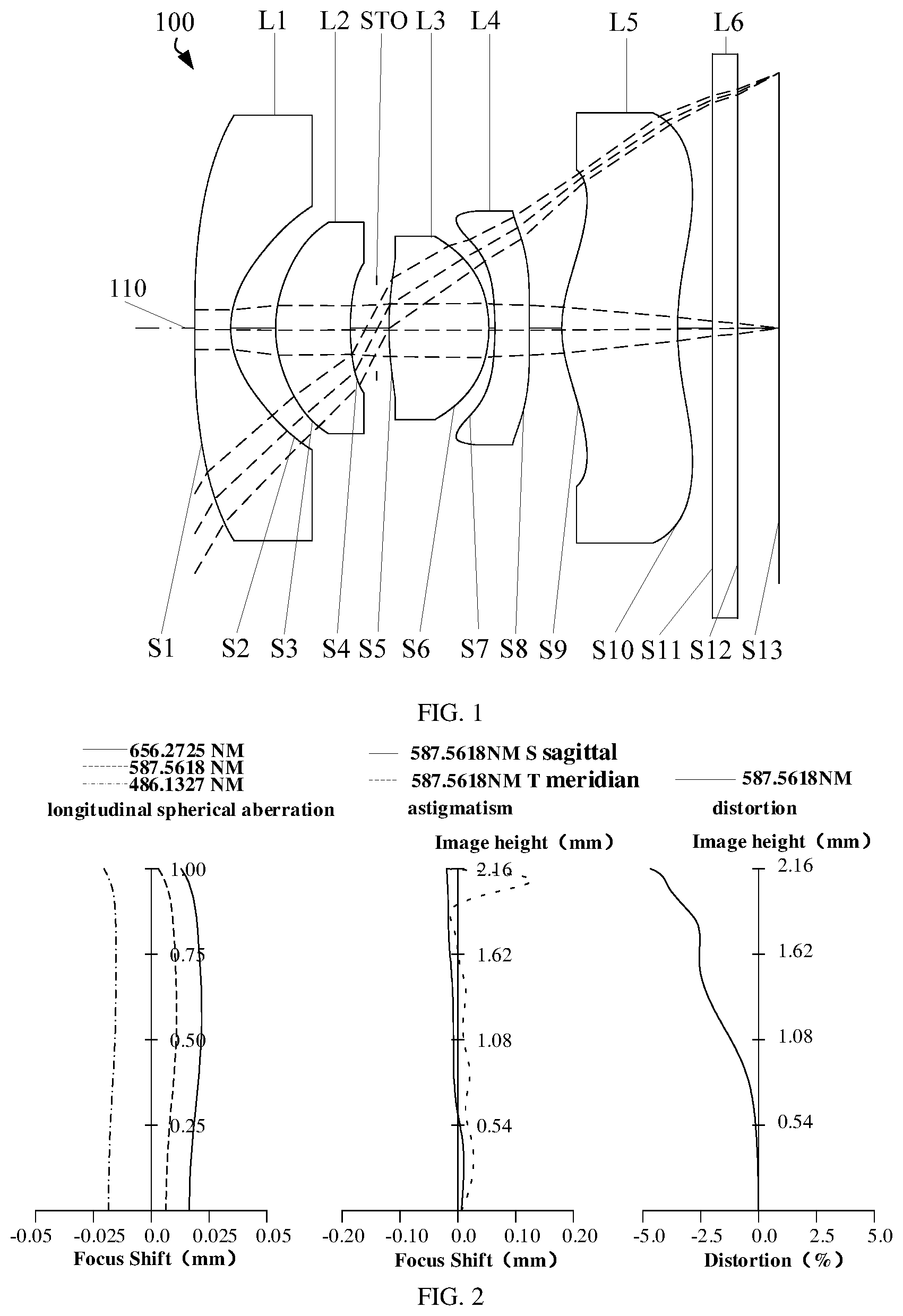
Referring to , according to some embodiments of the present disclosure, an optical system 100 includes, successively in order from an object side to an image side, a first lens L 1 , a second lens L 2 , a third lens L 3 , a fourth lens L 4 , and a fifth lens L 5 . Specifically, the first lens L 1 includes an object side surface S 1 and an image side surface S 2 . The second lens L 2 includes an object side surface S 3 and an image side surface S 4 . The third lens L 3 includes an object side surface S 5 and an image side surface S 6 . The fourth lens L 4 includes an object side surface S 7 and an image side surface S 8 . The fifth lens L 5 includes an object side surface S 9 and an image side surface S 10 . The first lens L 1 , the second lens L 2 , the third lens L 3 , the fourth lens L 4 , and the fifth lens L 5 are coaxially arranged. A common axis of the lenses in the optical system 100 is an optical axis 110 of the optical system 100 .
The first lens L 1 has a negative refractive power, and the image side surface S 2 of the first lens L 1 is concave at the near optical axis 110 , which is beneficial to the incidence of large-angle light into the optical system 100 , thereby facilitating the realization of wide-angle characteristics. The second lens L 2 has a positive refractive power. The object side surface S 3 of the second lens L 2 is convex near the optical axis 110 , and the image side surface S 4 thereof is concave near the optical axis 110 , which is beneficial to correct aberration such as spherical aberration generated by the first lens L 1 , while enabling the smooth transition of the light, thereby helping to improve the imaging quality of the optical system 100 . The third lens L 3 has a positive refractive power. The object side surface S 5 and the image side surface S 6 of the third lens L 3 are convex near the optical axis 110 , which can effectively converge the light to reduce the angle of the incident light, such that the smooth transition of the light can be realized. Moreover, it is beneficial to shorten the total length of the optical system 100 . The fourth lens L 4 has a negative refractive power, which can match with the positive refractive power of the third lens L 3 . As such, it is beneficial for the light emitted by the second lens L 2 to be smoothly transitioned to the fifth lens L 5 . The fifth lens L 5 has a positive refractive power. The object side surface S 9 of the fifth lens L 5 is convex near the optical axis 110 , and the image side surface S 10 thereof is concave near the optical axis 110 , which is beneficial to correct the curvature of field, astigmatism and the high-order aberration of the large-angle field of view of the optical system 100 , thereby improving the imaging quality of the optical system 100 . With the above-mentioned refractive power and surface shape features, when the optical system 100 has wide-angle characteristics, the distortion and aberration will not be too large, which is beneficial to improve the realism of the image restitution, thereby improving the user's experience.
In addition, in some embodiments, the optical system 100 further includes a stop STO. The stop STO may be provided between the second lens L 2 and the third lens L 3 . In some embodiments, the optical system 100 further includes an infrared filter L 6 provided on an image side of the fifth lens L 5 . The infrared filter L 6 may be an infrared cut-off filter, which is used to filter out interference light, so as to prevent the interference light from reaching the imaging surface of the optical system 100 and affecting normal imaging. Further, the optical system 100 further includes an image surface S 13 on the image side of the fifth lens L 5 . The image surface S 13 is the imaging surface of the optical system 100 . The incident light adjusted by the first lens L 1 , the second lens L 2 , the third lens L 3 , the fourth lens L 4 , and the fifth lens L 5 can be imaged on the image surface S 13 .
In some embodiments, the object side surface and the image side surface of each lens of the optical system 100 are both aspherical. The use of an aspheric structure can improve the flexibility of lens design, effectively correct spherical aberration, and improve imaging quality. In other embodiments, the object side surface and the image side surface of each lens of the optical system 100 may also be spherical. It should be noted that the above-mentioned embodiments are only examples of some embodiments of the present disclosure. In some embodiments, the surfaces of the lenses in the optical system 100 may be any combination of the spherical surface and the aspheric surface.
In some embodiments, the lenses in the optical system 100 may be made of glass or plastic. The lens made of plastic can reduce the weight of the optical system 100 and reduce the production cost, which can realize the thin and light design of the optical system 100 with the small size of the optical system 100 . The lens made of glass enables the optical system 100 to have excellent optical performance and higher temperature resistance. It should be noted that the lenses in the optical system 100 can also made of any combination of glass and plastic, and not necessarily all of them are made of glass or plastic.
It should be noted that the first lens L 1 does not necessary include only one lens. In some embodiments, there may also be two or more lenses in the first lens L 1 , and the two or more lenses can form a cemented lens. A surface of the cemented lens closest to the object side can be regarded as the object side surface S 1 , and a surface thereof closest to the image side can be regarded as the image side surface S 2 . Alternatively, the lenses in the first lens L 1 does not form the cemented lens, but the distance between the lenses is relatively fixed. In this case, the object side surface of the lenses closest to the object side is the object side surface S 1 , and the image side surface of the lenses closest to the image side is the image side surface S 2 . In addition, in some embodiments, two or more lenses may also be arranged in the second lens L 2 , the third lens L 3 , the fourth lens L 4 , or the fifth lens L 5 . Any adjacent lenses may form the cemented lens, or a non-cemented lens.
Further, in some embodiments, the optical system 100 satisfies a condition: 0.58≤R12/f≤0.71, where R12 is a radius of curvature of the image side surface S 2 of the first lens L 1 at the optical axis 110 , and f is an effective focal length of the optical system 100 . Specifically, the value of R12/f may be 0.581, 0.585, 0.590, 0.592, 0.598, 0.634, 0.648, 0.673, 0.688 or 0.701. When the above condition is satisfied, the ratio of the radius of curvature of the image side surface S 2 of the first lens L 1 at the optical axis 110 to the effective focal length of the optical system 100 can be reasonably configured, cooperating with the image side surface S 2 of the first lens L 1 having the concave shape, it is beneficial to enlarge the angle of field of view of the optical system 100 , enable the optical system 100 to have wide-angle characteristics, and while it is also beneficial to prevent the image side surface S 2 of the first lens L 1 from being excessively curved in shape, thereby helping to reduce the designing and forming difficulty of the first lens L 1 . If the upper limit of the above condition is exceeded, the radius of curvature of the image side surface S 2 of the first lens L 1 at the optical axis 110 will be too large, the image side surface S 2 of the first lens L 1 will be too smooth in shape, which results in that the large-angle light is not easily deflected by the first lens L 1 into the second lens L 2 and the third lens L 3 , which is disadvantageous to the realization of wide-angle characteristics. If the lower limit of the above condition is not reached, the radius of curvature of the image side surface S 2 of the first lens L 1 at the optical axis 110 will be too small, the image side surface S 2 of the first lens L 1 will be excessively curved in shape, and the edge inclination angle of the image side surface S 2 of the first lens L 1 is also increased therewith. As such, it will easily lead to an increase in tolerance sensitivity of the first lens L 1 and poor manufacturability, which is disadvantageous to the design and manufacture of the first lens L 1 .
In some embodiments, the optical system 100 satisfies a condition: −0.7≤f12/f45<0; where f12 is a combined focal length of the first lens L 1 and the second lens L 2 , and f45 is a combined focal length of the fourth lens L 4 and the fifth lens L 5 . Specifically, the value of f12/f45 may be: −0.631, −0.625, −0.613, −0.587, −0.573, −0.555, −0.527, −0.519, −0.453, or −0.404. When the above condition is satisfied, the ratio of the combined focal length of the first lens L 1 and the second lens L 2 to the combined focal length of the fourth lens L 4 and the fifth lens L 5 can be reasonably configured, which facilitates the large-angle light incident to the first lens L 1 and the second lens L 2 . As such, it is beneficial to realize the wide-angle characteristics of the optical system 100 , and while it is also beneficial for the fourth lens L 4 and the fifth lens L 5 to correct the aberration of the optical system 100 , and beneficial to shorten the total length of the optical system 100 . In addition, it is also beneficial to for two lens group at the object side and the image side of the third lens L 3 to match with two convex surfaces of the third lens L 3 , which is beneficial to suppress the distortion of the optical system 100 , improving the image restitution degree of the optical system 100 . If the lower limit of the above condition is not reached, the refractive power provided by the first lens L 1 and the second lens L 2 is too small, which is out of balance with the refractive power of the fourth lens L 4 and the fifth lens L 5 , which is disadvantageous for the two lens group at the object side and the image side of the third lens L 3 to match with the third lens L 3 , and thus is disadvantageous to improve the imaging quality of the optical system 100 .
In some embodiments, the optical system 100 satisfies a condition: 1.6≤f2/f3≤2.1; where f2 is an effective focal length of the second lens L 2 , and f3 is an effective focal length of the third lens L 3 . Specifically, the value of f2/f3 may be: 1.682, 1.712, 1.735, 1.786, 1.822, 1.847, 1.889, 1.924, 1.955, or 2.019. When the above condition is satisfied, a ratio of the effective focal length the second lens L 2 to the effective focal length of the third lens L 3 can be reasonably configured, which is beneficial for the second lens L 2 to match with the first lens L 1 , thereby helping to correct the severe spherical aberrations generated by the first lens L 1 . In addition, it is also beneficial for the third lens L 3 to provide sufficient positive refractive power for the optical system 100 , thereby shortening the total length of the optical system 100 , and while the third lens L 3 has sufficient central thickness to suppress the increase in sensitivity cause by the light deflection angle becoming larger. As such, it is beneficial to correct the aberration of the optical system 100 and suppress large-angle optical distortion, thereby helping to solve the problems that the severely distortion generated when the optical system 100 realizes the wide-angle characteristics causes the edge of the captured picture to be distorted.
In some embodiments, the optical system 100 satisfies a condition: 0.3≤ΣT/ΣCT≤0.55; where ΣT is a sum of the intervals between two adjacent lenses among the first lens L 1 , the second lens L 2 , the third lens L 3 , the fourth lens L 4 , and the fifth lens L 5 on the optical axis 110 , ΣCT is a sum of the thicknesses of the first lens L 1 , the second lens L 2 , the third lens L 3 , the fourth lens L 4 , and the fifth lens L 5 on the optical axis 110 . Specifically, the value of ΣT/ΣCT may be: 0.338, 0.357, 0.386, 0.412, 0.435, 0.478, 0.493, 0.511, 0.515 or 0.520. When the above condition is satisfied, the center thicknesses of and the intervals between the five lenses in the optical system 100 can be reasonably configured, which is beneficial to a more compact structure of the optical system 100 , and thus it is beneficial to shorten the total optical length, and while it also prevents the center thicknesses of and the intervals between the five lenses from being not too extreme, which helps to improve the manufacturability of the optical system 100 . If the upper limit of the above condition is exceeded, the intervals between the five lenses is too large, which is disadvantageous to shorten the total length of the optical system 100 . If the lower limit of the above condition is not reached, the intervals between the five lenses are too small, resulting in that the space used to deflect the light is limited, and the light deflection angle increases, which is disadvantageous to correct the aberrations of the optical system 100 , nor beneficial to the assembly of the optical system 100 .
In some embodiments, the optical system 100 satisfies a condition: 1.8≤ΣT1/CT1≤2.9; where ΣT1 is a distance from a portion of the object side surface S 1 having the maximum effective aperture to a portion of the image side surface S 2 having the maximum effective aperture of the first lens L 1 in a direction of the optical axis 110 , CT1 is a thickness of the first lens L 1 on the optical axis 110 . Specifically, the value of ΣT1/CT1 may be: 1.940, 1.974, 2.026, 2.134, 2.257, 2.364, 2.455, 2.637, 2.722, or 2.887. When the above condition is satisfied, a ratio of the edge thickness to the center thickness of the first lens L 1 can be reasonably configured, such that the first lens L 1 will not be excessively curved in shape, which is beneficial to the design and forming of the first lens L 1 , thereby improving the manufacturability of the first lens L 1 , and while it is also beneficial to reduce the thickness of the first lens L 1 as much as possible, thereby reducing the size of the front portion of the optical system 100 . If the lower limit of the above condition is not reached, the edge thickness of the first lens L 1 is too small, causing the first lens L 1 to be excessively curved in shape, which is disadvantageous to the forming of the first lens L 1 , and reduces the manufacturability of the first lens L 1 . If the upper limit of the above condition is exceeded, the edge thickness of the first lens L 1 is too large, causing the size of the front portion of the optical system 100 to be too large, which is disadvantageous to the assembly of the optical system 100 .
In some embodiments, the optical system 100 satisfies a condition: 0.9≤Y11/Y52≤1.1; where Y11 is the maximum effective aperture of the object side surface S 1 of the first lens L 1 , and Y52 is the maximum effective aperture of the image side surface S 10 of the fifth lens L 5 . Specifically, the value of Y11/Y52 may be 0.957, 0.963, 0.975, 0.986, 0.994, 1.021, 1.034, 1.055, 1.064, or 1.075. When the above condition is satisfied, a ratio of the maximum effective aperture of the object side surface S 1 of the first lens L 1 to the maximum effective aperture of the image side surface S 10 of the fifth lens L 5 can be reasonably configured, such that an aperture of the front portion is similar to an aperture of the rear portion of the optical system 100 . The structure of optical system 100 can have a better symmetry, which is more beneficial to correct the aberration of the optical system 100 , suppressing the distortion of the optical system 100 , and thereby improving the imaging quality of the optical system 100 .
In some embodiments, the optical system 100 satisfies a condition: 0.6≤BFL/f≤0.8; where BFL is a distance from the image side surface S 10 of the fifth lens L 5 to the imaging surface of the optical system 100 on the optical axis 110 . Specifically, the value of BFL/f may be 0.645, 0.653, 0.668, 0.672, 0.685, 0.699, 0.705, 0.718, 0.726 or 0.731. When the above condition is satisfied, a ratio of the optical back focus to the effective focal length of the optical system 100 can be reasonably configured, such that the optical system 100 has enough back focus space to move back and forth to focus, and it also easier for the optical system 100 to match with a photosensitive element, and thus which is beneficial to improve the imaging quality of the optical system 100 . In addition, the optical back focus of the optical system 100 is not too long, such that is beneficial to shorten the total length of the optical system 100 . If the lower limit of the above condition is not reached, the optical back focus of the optical system 100 is too small, resulting in the chief ray angle (CRA) of the optical system 100 being limited, which is disadvantageous for the optical system 100 to match with the photosensitive element. If the upper limit of the above condition is exceeded, the optical back focus of the optical system 100 is too long, which is disadvantageous to shorten the total length of the optical system 100 , and which is thus disadvantageous to the application of the optical system 100 in portable electronic devices.
In some embodiments, the optical system 100 satisfies a condition: 55 deg/mm≤FOV/ImgH≤57 deg/mm; where FOV is the maximum angle of field of view of the optical system 100 , and ImgH is half of the image height of the optical system 100 corresponding to the maximum angle of field of view. Specifically, the value of FOV/ImgH may be: 55.556, 55.633, 55.715, 55.812, 55.936, 56.217, 56.359, 56.402, 56.474 or 56.542, in unit of deg/mm. When the above condition is satisfied, a ratio of the maximum angle of field of view to the half-image height of the optical system 100 can be reasonably configured, which is beneficial to expand the angle of field of view of the optical system 100 , achieving wide-angle characteristics, and enabling the optical system 100 to capture pictures in a wider range. Moreover, it is also beneficial to increase the size of the imaging surface of the optical system 100 , such that the optical system 100 can match with a larger-sized photosensitive element, thereby helping to increase the pixels of the optical system 100 . In addition, the angle of field of view of the optical system 100 is not too large, which is beneficial to the correction of the distortion and aberration of the optical system 100 . If the upper limit of the above condition is exceeded, the angle of field of view of the optical system 100 is too large, resulting in difficulty in the correction of distortion and aberrations of the optical system 100 , thereby resulting in unclear imaging and severe image distortion of the optical system 100 . If the lower limit of the above condition is not reached, the angle of field of view of the optical system 100 is too small, which is difficult to meet the requirements of capturing in large range.
It should be noted that, in some embodiments, the optical system 100 may match with the photosensitive element having a rectangular photosensitive surface, and the imaging surface of the optical system 100 coincides with the photosensitive surface of the photosensitive element. In this case, the effective pixel area on the imaging surface of the optical system 100 has a horizontal direction and a diagonal direction, the FOV can be understood as the maximum angle of field of view of the optical system 100 in the diagonal direction, and ImgH can be understood as half of the length of the effective pixel area on the imaging surface of the optical system 100 in the diagonal direction.
In some embodiments, the optical system 100 satisfies a condition: |DIST|≤5%; where DIST is the maximum of the optical distortion of the optical system 100 . Specifically, the value of DIST may be: 3.000, 3.670, 4.600, 4.830, or 5.000, in unit of %. When the above condition is satisfied, the distortion of the optical system 100 can be suppressed while realizing the wide-angle characteristics, thereby improving the realism of the picture restitution and enhancing the consumer's experience.
In some embodiments, the optical system 100 satisfies a condition: n2+n4≥3.32; where n2 is the refractive index of the second lens L 2 at a wavelength of 587.5618 nm, and n4 is the refractive index of the fourth lens L 4 at the wavelength of 587.5618 nm. Specifically, the value of n2+n4 may be: 3.320, 3.322, 3.324, 3.327, 3.328, 3.301, 3.325, 3.326, 3.329 or 3.332. When the above condition is satisfied, the refractive indices of the second lens L 2 and the fourth lens L 4 can be reasonably configured, thereby improving the modulation transfer function of the optical system 100 , facilitating correcting the chromatic aberration of the optical system 100 , and improving the resolution of the optical system 100 . If the lower limit of the above condition is not reached, the refractive index of the second lens L 2 and the fourth lens L 4 is insufficient, which is disadvantageous to converge the light, resulting in insufficient aberration correction of the optical system 100 .
A reference wavelength of the above effective focal length and combined focal length is 587.5618 nm.
Based on the description of the foregoing embodiments, more specific embodiments and drawings are illustrated below for detailed description.
First Embodiment
is a schematic view of an optical system 100 according to a first embodiment. The optical system 100 includes, successively in order from an object side to an image side, a first lens L 1 having a negative refractive power, a second lens L 2 having a positive refractive power, a stop STO, a third lens L 3 having a positive refractive power, a fourth lens L 4 having a negative refractive power, and a fifth lens L 5 having a positive refractive power. is a graph showing longitudinal spherical aberration, astigmatism, and distortion of the optical system 100 according to the first embodiment in order from left to right, where the reference wavelength of the astigmatism diagram and the distortion diagram is 587.5618 nm, and which are the same as other embodiments.
An object side surface S 1 of the first lens L 1 is convex near an optical axis 110 and convex at a circumference thereof.
An image side surface S 2 of the first lens L 1 is concave near the optical axis 110 and concave at the circumference thereof.
An object side surface S 3 of the second lens L 2 is convex near the optical axis 110 and convex at a circumference thereof.
An image side surface S 4 of the second lens L 2 is concave near the optical axis 110 and concave at the circumference thereof.
An object side surface S 5 of the third lens L 3 is convex near the optical axis 110 and convex at a circumference thereof.
An image side surface S 6 of the third lens L 3 is convex near the optical axis 110 and convex at the circumference thereof.
An object side surface S 7 of the fourth lens L 4 is concave near the optical axis 110 and concave at a circumference thereof.
An image side surface S 8 of the fourth lens L 4 is concave near the optical axis 110 and convex at the circumference thereof.
An object side surface S 9 of the fifth lens L 5 is convex near the optical axis 110 and concave at a circumference thereof.
An image side surface S 10 of the fifth lens L 5 is concave near the optical axis 110 and convex at the circumference thereof.
The object side surfaces and the image side surfaces of the first lens L 1 , the second lens L 2 , the third lens L 3 , the fourth lens L 4 , and the fifth lens L 5 are all aspherical.
It should be noted that in this disclosure, when describing that a surface of the lens at the optical axis 110 (a central area of the surface) is convex, it can be understood that an area of this surface of the lens near the optical axis 110 is convex. When describing a surface of the lens is concave at a circumference thereof, it can be understood that an area of this surface approaching the maximum effective radius is concave. For example, when this surface is convex near the optical axis 110 and is also convex at a circumference thereof, a shape of this surface in a direction from its center (an intersection between this surface and the optical axis 110 ) to its edge may be completely convex, or may be firstly convex at its center and be then transitioned to be concave, and then become convex when approaching the maximum effective radius. These are only examples to illustrate the relationships between various shapes and structures (concave-convex relationships) of the surface at the optical axis 110 and at the circumference, and the various shapes and structures (concave-convex relationships) of the surface are not fully described, but other situations can be derived from the above examples.
The first lens L 1 , the second lens L 2 , the third lens L 3 , the fourth lens L 4 , and the fifth lens L 5 are all made of plastic.
Further, the optical system 100 satisfies a condition: R12/f=0.599; where R12 is a radius of curvature of the image side surface S 2 of the first lens L 1 at the optical axis 110 , and f is an effective focal length of the optical system 100 . When the above condition is satisfied, the ratio of the radius of curvature of the image side surface S 2 of the first lens L 1 at the optical axis 110 to the effective focal length of the optical system 100 can be reasonably configured, cooperating with the image side surface S 2 of the first lens L 1 having the concave shape, it is beneficial to enlarge the angle of field of view of the optical system 100 , enable the optical system 100 to have wide-angle characteristics, and while it is also beneficial to prevent the image side surface S 2 of the first lens L 1 from being excessively curved in shape, thereby helping to reduce the designing and forming difficulty of the first lens L 1 .
The optical system 100 satisfies a condition: f12/f45=−0.450; where f12 is a combined focal length of the first lens L 1 and the second lens L 2 , and f45 is a combined focal length of the fourth lens L 4 and the fifth lens L 5 . When the above condition is satisfied, the ratio of the combined focal length of the first lens L 1 and the second lens L 2 to the combined focal length of the fourth lens L 4 and the fifth lens L 5 can be reasonably configured, which facilitates the large-angle light incident to the first lens L 1 and the second lens L 2 . As such, it is beneficial to realize the wide-angle characteristics of the optical system 100 , and while it is also beneficial for the fourth lens L 4 and the fifth lens L 5 to correct the aberration of the optical system 100 , and beneficial to shorten the total length of the optical system 100 . In addition, it is also beneficial to for two lens group at the object side and the image side of the third lens L 3 to match with two convex surfaces of the third lens L 3 , which is beneficial to suppress the distortion of the optical system 100 , improving the image restitution degree of the optical system 100 .
The optical system 100 satisfies a condition: f2/f3=1.682; where f2 is an effective focal length of the second lens L 2 , and f3 is an effective focal length of the third lens L 3 . When the above condition is satisfied, a ratio of the effective focal length the second lens L 2 to the effective focal length of the third lens L 3 can be reasonably configured, which is beneficial for the second lens L 2 to match with the first lens L 1 , thereby helping to correct the severe spherical aberrations generated by the first lens L 1 . In addition, it is also beneficial for the third lens L 3 to provide sufficient positive refractive power for the optical system 100 , thereby shortening the total length of the optical system 100 , and while the third lens L 3 has sufficient central thickness to suppress the increase in sensitivity cause by the light deflection angle becoming larger. As such, it is beneficial to correct the aberration of the optical system 100 and suppress large-angle optical distortion, thereby helping to solve the problems that the severely distortion generated when the optical system 100 realizes the wide-angle characteristics causes the edge of the captured picture to be distorted.
The optical system 100 satisfies a condition: ΣT/ΣCT=0.338; where ΣT is the sum of the interval between two adjacent lenses among the first lens L 1 , the second lens L 2 , the third lens L 3 , the fourth lens L 4 , and the fifth lens L 5 on the optical axis 110 , ΣCT is the sum of the thicknesses of the first lens L 1 , the second lens L 2 , the third lens L 3 , the fourth lens L 4 , and the fifth lens L 5 on the optical axis 110 . When the above condition is satisfied, the center thicknesses of and the intervals between the five lenses in the optical system 100 can be reasonably configured, which is beneficial to a more compact structure of the optical system 100 , and thus it is beneficial to shorten the total optical length, and while it also prevents the center thicknesses of and the intervals between the five lenses from being not too extreme, which helps to improve the manufacturability of the optical system 100 .
The optical system 100 satisfies a condition: ΣT1/CT1=2.167; where ΣT1 is a distance from a portion of the object side surface S 1 having the maximum effective aperture to a portion of the image side surface S 2 having the maximum effective aperture of the first lens L 1 in a direction of the optical axis 110 , CT1 is a thickness of the first lens L 1 on the optical axis 110 . When the above condition is satisfied, the ratio of the edge thickness to the center thickness of the first lens L 1 can be reasonably configured, such that the first lens L 1 will not be excessively curved in shape, which is beneficial to the design and forming of the first lens L 1 , thereby improving the manufacturability of the first lens L 1 , and while it is also beneficial to reduce the thickness of the first lens L 1 as much as possible, thereby reducing the size of the front portion of the optical system 100 .
The optical system 100 satisfies a condition: Y11/Y52=0.989; where Y11 is the maximum effective aperture of the object side surface S 1 of the first lens L 1 , and Y52 is the maximum effective aperture of the image side surface S 10 of the fifth lens L 5 . When the above condition is satisfied, the ratio of the maximum effective aperture of the object side surface S 1 of the first lens L 1 to the maximum effective aperture of the image side surface S 10 of the fifth lens L 5 can be reasonably configured, such that an aperture of the front portion is similar to an aperture of the rear portion of the optical system 100 . The structure of optical system 100 can have a better symmetry, which is more beneficial to correct the aberration of the optical system 100 , suppressing the distortion of the optical system 100 , and thereby improving the imaging quality of the optical system 100 .
The optical system 100 satisfies a condition: BFL/f=0.645; where BFL is a distance from the image side surface S 10 of the fifth lens L 5 to the imaging surface of the optical system 100 on the optical axis 110 . When the above condition is satisfied, the ratio of the optical back focus to the effective focal length of the optical system 100 can be reasonably configured, such that the optical system 100 has enough back focus space to move back and forth to focus, and it also easier for the optical system 100 to match with a photosensitive element, and thus which is beneficial to improve the imaging quality of the optical system 100 . In addition, the optical back focus of the optical system 100 is not too long, such that is beneficial to shorten the total length of the optical system 100 .
The optical system 100 satisfies a condition: FOV/ImgH=55.556 deg/mm; where FOV is the maximum angle of field of view of the optical system 100 , and ImgH is half of the image height of the optical system 100 corresponding to the maximum angle of field of view. When the above condition is satisfied, the ratio of the maximum angle of field of view to the half-image height of the optical system 100 can be reasonably configured, which is beneficial to expand the angle of field of view of the optical system 100 , achieving wide-angle characteristics, and enabling the optical system 100 to capture pictures in a wider range. Moreover, it is also beneficial to increase the size of the imaging surface of the optical system 100 , such that the optical system 100 can match with a larger-sized photosensitive element, thereby helping to increase the pixels of the optical system 100 . In addition, the angle of field of view of the optical system 100 is not too large, which is beneficial to the correction of the distortion and aberration of the optical system 100 .
The optical system 100 satisfies a condition: |DIST|=4.600%; where DIST is the maximum of the optical distortion of the optical system 100 . When the above condition is satisfied, the distortion of the optical system 100 can be suppressed while realizing the wide-angle characteristics, thereby improving the realism of the picture restitution and enhancing the consumer's experience.
The optical system 100 satisfies a condition: n2+n4=3.322; where n2 is the refractive index of the second lens L 2 at a wavelength of 587.5618 nm, and n4 is the refractive index of the fourth lens L 4 at the wavelength of 587.5618 nm. When the above condition is satisfied, the refractive indices of the second lens L 2 and the fourth lens L 4 can be reasonably configured, thereby improving the modulation transfer function of the optical system 100 , facilitating correcting the chromatic aberration of the optical system 100 , and improving the resolution of the optical system 100 .
In addition, parameters of the optical system 100 are shown in Table 1. The image surface S 3 in Table 1 can be understood as an imaging surface of the optical system 100 . The elements from the object surface (not shown in figures) to the image surface 13 are arranged in the order of the elements in Table 1 from top to bottom. The Y radius in Table 1 is the radius of curvature of the object side surface or image side surface indicated by corresponding surface number at the optical axis 110 . The surface numbers 1 and 2 indicate the object side surface S 1 and the image side surface S 2 of the first lens L 1 , respectively. That is, in the same lens, the surface with the smaller surface number is the object side surface, and the surface with the larger surface number is the image side surface. In the “thickness” parameter column of the first lens, the first value is the thickness of this lens on the optical axis 110 , and the second value is a distance from the image side surface of this lens to the next surface in a direction toward the image side on the optical axis 110 .
It should be noted that in this embodiment and the following various embodiments, the optical system 100 may not be provided with an infrared filter L 6 , but in this case, a distance from the image side surface S 10 to the image side surface S 13 of the fifth lens L 5 remains unchanged.
In the first embodiment, the effective focal length of the optical system 10 is indicated by f, and f=1.309 mm. The f-number is indicated by FNO, and FNO=2.30. The maximum angle of field of view is indicated by FOV, and FOV=120 deg. The total optical length is indicated by TTL, and TTL=4.57 mm. In the first embodiment and other embodiments, the optical system 100 satisfies: 115 deg≤FOV≤125 deg. It can be seen that the optical system 100 has wide-angle characteristics and can meet the requirements of capturing in a wide range. In addition, the optical system 100 has wide-angle characteristics and small distortion, high image restitution, and good imaging quality.
The reference wavelengths of the focal length, the refractive index, and the Abbe number of each lens are all 587.5618 nm, and which are the same in other embodiments.
TABLE 1
First Embodiment
f = 1.309 mm, FNO = 2.30, FOV = 120.0 deg, TTL = 4.57 mm
Focal
Surface Surface Surface Y radius Thickness Refractive Abbe Length
Number Name Shape (mm) (mm) Material index number (mm)
Object Spherical Infinite 1000.00
Surface
S1 First Aspherical 38.501 0.300 Plastic 1.535 55.751 −1.500
S2 Lens Aspherical 0.784 0.374
S3 Second Aspherical 1.077 0.623 Plastic 1.661 20.370 2.656
S4 Lens Aspherical 2.146 0.220
Stop Spherical Infinite 0.102
S5 Third Aspherical 2.988 0.831 Plastic 1.535 55.751 1.579
S6 Lens Aspherical −1.063 0.050
S7 Fourth Aspherical −2.916 0.287 Plastic 1.661 20.370 −3.952
S8 Lens Aspherical 25.946 0.270
S9 Fifth Aspherical 1.047 0.964 Plastic 1.535 55.751 2.706
S10 Lens Aspherical 2.571 0.290
S11 Infrared Spherical Infinite 0.210 Glass 1.517 64.167
S12 Filter Spherical Infinite 0.344
S13 Image Spherical Infinite 0.000
Surface
Further, the aspheric coefficients of the image side surface or the object side surface of the lenses of the optical system 100 are shown in Table 2. The surface numbers of S 1 to S 10 indicate the image side surface or the object side surface S 1 to S 10 , respectively. K to A20 from top to bottom respectively represent the types of aspherical coefficients, where K represents the conic coefficient, A4 represents the fourth-order aspheric coefficient, A6 represents the sixth-order aspheric coefficient, and A8 represents the eighth-order aspheric coefficient, and so on. In addition, the aspheric coefficient formula is as follows:
Z = cr 2 1 + 1 - ( k + 1 ) c 2 r 2 + ∑ i Ai r i where Z is a distance from a corresponding point on an aspheric surface to a plane tangent to a vertex of the surface, r is a distance from a corresponding point on the aspheric surface to the optical axis 110 , c is a curvature of the vertex of the aspheric surface, k is a conic coefficient, and Ai is a coefficient corresponding to the i th high-order term in the aspheric surface shape formula.
TABLE 2
First Embodiment
Aspheric Coefficient
Surface
Number S1 S2 S3 S4 S5
K −9.900E+01 −1.438E+00 −1.577E−01 1.887E+00 7.901E+00
A4 9.937E−02 2.474E−01 −8.695E−02 2.111E−01 −6.801E−02
A6 −6.255E−02 −1.267E+00 −3.478E−01 1.540E+00 7.344E−01
A8 −1.709E−02 8.362E+00 4.259E+00 −3.249E+01 −1.435E+01
A10 6.592E−02 −3.402E+01 −2.588E+01 4.490E+02 1.289E+02
A12 −5.478E−02 7.942E+01 8.687E+01 −3.552E+03 −7.162E+02
A14 2.435E−02 −1.119E+02 −1.710E+02 1.746E+04 2.486E+03
A16 −6.297E−03 9.579E+01 2.015E+02 −5.218E+04 −5.276E+03
A18 8.941E−04 −4.604E+01 −1.322E+02 8.660E+04 6.283E+03
A20 −5.389E−05 9.538E+00 3.705E+01 −6.111E+04 −3.218E+03
Surface
Number S6 S7 S8 S9 S10
K 4.454E−01 −8.690E+01 −9.900E+01 −5.005E+00 −5.690E−01
A4 6.444E−01 3.021E−01 −1.872E−01 −1.131E−01 −2.744E−02
A6 −1.221E+01 −1.071E+01 −1.639E+00 1.040E−01 −1.155E−01
A8 8.469E+01 6.881E+01 9.201E+00 −5.969E−01 6.248E−02
A10 −3.618E+02 −2.675E+02 −2.613E+01 1.730E+00 5.955E−02
A12 1.012E+03 6.751E+02 4.677E+01 −2.734E+00 −1.091E−01
A14 −1.878E+03 −1.122E+03 −5.492E+01 2.552E+00 7.303E−02
A16 2.242E+03 1.182E+03 4.123E+01 −1.410E+00 −2.574E−02
A18 −1.569E+03 −7.062E+02 −1.793E+01 4.265E−01 4.711E−03
A20 4.903E+02 1.806E+02 3.435E+00 −5.448E−02 −3.525E−04
In addition, includes a longitudinal spherical aberration diagram of the optical system 100 , which shows that light of different wavelengths deviates from the focal point after transmitting through the lenses. The ordinate of the longitudinal spherical aberration diagram represents the normalized pupil coordinator from the center of the pupil to the edge of the pupil, and the abscissa thereof represents the distance from the imaging surface to the intersection of the light and the optical axis 110 (in unit of mm). It can be seen from the longitudinal spherical aberration diagram that the deviation degree of the convergence point of the light of various wavelength in the first embodiment tends to be the same, and the diffuse spot or chromatic halo in the imaged picture is effectively prevented. further includes an astigmatic field curves diagram of the optical system 100 , where the S curve represents the sagittal field curvature at 587.5618 nm, and the T curve represents the meridian field curvature at 587.5618 nm. It can be seen from the diagram that the field curvature of the optical system 100 is small, the field curvature and astigmatism of each field of view are well corrected, and clear imaging can be achieved at the center and edges of the field of view. further includes a distortion diagram of the optical system 100 . It can be seen from the diagram that the image distortion caused by the main beam is small, and the imaging quality of the system is excellent.
Second Embodiment
is a schematic view of an optical system 100 according to a second embodiment. The optical system 100 includes, successively in order from an object side to an image side, a first lens L 1 having a negative refractive power, a second lens L 2 having a positive refractive power, a stop STO, a third lens L 3 having a positive refractive power, a fourth lens L 4 having a negative refractive power, and a fifth lens L 5 having a positive refractive power. is a graph showing longitudinal spherical aberration, astigmatism, and distortion of the optical system 100 according to the second embodiment in order from left to right.
An object side surface S 1 of the first lens L 1 is convex near an optical axis 110 and convex at a circumference thereof.
An image side surface S 2 of the first lens L 1 is concave near the optical axis 110 and concave at the circumference thereof.
An object side surface S 3 of the second lens L 2 is convex near the optical axis 110 and convex at a circumference thereof.
An image side surface S 4 of the second lens L 2 is concave near the optical axis 110 and concave at the circumference thereof.
An object side surface S 5 of the third lens L 3 is convex near the optical axis 110 and convex at a circumference thereof.
An image side surface S 6 of the third lens L 3 is convex near the optical axis 110 and convex at the circumference thereof.
An object side surface S 7 of the fourth lens L 4 is concave near the optical axis 110 and concave at a circumference thereof.
An image side surface S 8 of the fourth lens L 4 is concave near the optical axis 110 and convex at the circumference thereof.
An object side surface S 9 of the fifth lens L 5 is convex near the optical axis 110 and concave at a circumference thereof.
An image side surface S 10 of the fifth lens L 5 is concave near the optical axis 110 and convex at the circumference thereof.
The object side surfaces and the image side surfaces of the first lens L 1 , the second lens L 2 , the third lens L 3 , the fourth lens L 4 , and the fifth lens L 5 are all aspherical.
The first lens L 1 , the second lens L 2 , the third lens L 3 , the fourth lens L 4 , and the fifth lens L 5 are all made of plastic.
In addition, various parameters of the optical system 100 are shown in Table 3, and the definition of each of the parameters can be obtained from the first embodiment, which will not be repeated herein.
TABLE 3
Second Embodiment
f = 1.207 mm, FNO = 2.08, FOV = 120.42 deg, TTL = 4.51 mm
Focal
Surface Surface Surface Y radius Thickness Refractive Abbe Length
Number Name Shape (mm) (mm) Material index number (mm)
Object Spherical Infinite 1005
Surface
S1 First Aspherical 15.519 0.309 Plastic 1.535 55.751 −1.450
S2 Lens Aspherical 0.734 0.353
S3 Second Aspherical 1.011 0.567 Plastic 1.671 19.244 2.829
S4 Lens Aspherical 1.676 0.252
Stop Spherical Infinite 0.050
S5 Third Aspherical 2.921 0.833 Plastic 1.535 55.751 1.445
S6 Lens Aspherical −0.947 0.050
S7 Fourth Aspherical −2.258 0.352 Plastic 1.661 20.370 −3.041
S8 Lens Aspherical 19.365 0.388
S9 Fifth Aspherical 0.822 0.799 Plastic 1.535 55.751 2.058
S10 Lens Aspherical 2.145 0.296
S11 Infrared Spherical Infinite 0.210 Glass 1.517 64.167
S12 Filter Spherical Infinite 0.360
S13 Image Spherical Infinite 0.000
Surface
Further, the aspheric coefficients of the image side surface or the object side surface of the lenses of the optical system 100 are shown in Table 4, and the definition of each of the parameters can be obtained from the first embodiment, and will not be repeated herein.
TABLE 4
Second Embodiment
Aspheric Coefficient
Surface
Number S1 S2 S3 S4 S5
K 5.135E+01 −1.291E+00 8.018E−02 6.238E+00 2.193E+00
A4 1.576E−01 3.118E−01 −7.003E−02 2.076E−01 1.218E−01
A6 −2.761E−01 −9.886E−01 −1.847E−01 −4.431E−02 −3.230E+00
A8 3.044E−01 3.715E+00 1.420E+00 −8.944E−01 6.555E+01
A10 −2.146E−01 −1.732E+01 −8.196E+00 7.837E+01 −8.424E+02
A12 1.008E−01 5.145E+01 2.606E+01 −7.277E+02 6.548E+03
A14 −3.109E−02 −8.628E+01 −3.259E+01 3.274E+03 −3.134E+04
A16 5.958E−03 8.154E+01 −7.013E+00 −7.028E+03 8.933E+04
A18 −6.286E−04 −3.918E+01 5.610E+01 4.521E+03 −1.377E+05
A20 2.677E−05 6.893E+00 −3.892E+01 2.797E+03 8.714E+04
Surface
Number S6 S7 S8 S9 S10
K 2.265E−01 −3.534E+00 −7.638E+01 −3.847E+00 −4.240E+00
A4 −6.698E−01 −1.473E+00 −1.455E+00 −1.693E−01 −7.300E−02
A6 1.121E+01 1.447E+01 6.787E+00 4.304E−01 4.602E−02
A8 −1.019E+02 −1.066E+02 −2.569E+01 −8.465E−01 −5.199E−02
A10 5.508E+02 5.074E+02 7.093E+01 1.054E+00 2.830E−02
A12 −1.952E+03 −1.656E+03 −1.380E+02 −8.652E−01 −4.812E−03
A14 4.516E+03 3.643E+03 1.820E+02 4.646E−01 −1.871E−03
A16 −6.514E+03 −5.161E+03 −1.536E+02 −1.572E−01 1.074E−03
A18 5.285E+03 4.258E+03 7.456E+01 3.031E−02 −2.099E−04
A20 −1.833E+03 −1.546E+03 −1.576E+01 −2.522E−03 1.584E−05
According to the information of parameters described above, the following data can be derived.
R12/f 0.608 Y11/Y52 0.957
f12/f45 −0.597 BFL/f 0.717
f2/13 1.958 FOV/ImgH (deg/mm) 55.750
ΣT/ΣCT 0.382 DIST (%) 5.000
ET1/CT1 2.006 n2 + n4 3.332
In addition, it can be seen from the aberration diagram in that the longitudinal spherical aberration, astigmatism, and distortion of the optical system 100 are well controlled, such that the optical system 100 of this embodiment has good imaging quality.
Third Embodiment
Referring to , is a schematic view of an optical system 100 according to a third embodiment. The optical system 100 includes, successively in order from an object side to an image side, a first lens L 1 having a negative refractive power, a second lens L 2 having a positive refractive power, a stop STO, a third lens L 3 having a positive refractive power, a fourth lens L 4 having a negative refractive power, and a fifth lens L 5 having a positive refractive power. is a graph showing longitudinal spherical aberration, astigmatism, and distortion of the optical system 100 according to the third embodiment in order from left to right.
An object side surface S 1 of the first lens L 1 is convex near an optical axis 110 and convex at a circumference thereof.
An image side surface S 2 of the first lens L 1 is concave near the optical axis 110 and concave at the circumference thereof.
An object side surface S 3 of the second lens L 2 is convex near the optical axis 110 and convex at a circumference thereof.
An image side surface S 4 of the second lens L 2 is concave near the optical axis 110 and concave at the circumference thereof.
An object side surface S 5 of the third lens L 3 is convex near the optical axis 110 and convex at a circumference thereof.
An image side surface S 6 of the third lens L 3 is convex near the optical axis 110 and convex at the circumference thereof.
An object side surface S 7 of the fourth lens L 4 is concave near the optical axis 110 and concave at a circumference thereof.
An image side surface S 8 of the fourth lens L 4 is concave near the optical axis 110 and convex at the circumference thereof.
An object side surface S 9 of the fifth lens L 5 is convex near the optical axis 110 and concave at a circumference thereof.
An image side surface S 10 of the fifth lens L 5 is concave near the optical axis 110 and convex at the circumference thereof.
The object side surfaces and the image side surfaces of the first lens L 1 , the second lens L 2 , the third lens L 3 , the fourth lens L 4 , and the fifth lens L 5 are all aspherical.
The first lens L 1 , the second lens L 2 , the third lens L 3 , the fourth lens L 4 , and the fifth lens L 5 are all made of plastic.
In addition, various parameters of the optical system 100 are shown in Table 5, and the definition of each of the parameters can be obtained from the first embodiment, which will not be repeated herein.
TABLE 5
Third Embodiment
f = 1.255 mm, FNO = 2.25, FOV = 122.13 deg, TTL = 4.50 mm
Focal
Surface Surface Surface Y radius Thickness Refractive Abbe Length
Number Name Shape (mm) (mm) Material index number (mm)
Object Spherical Infinite 1000
Surface
S1 First Aspherical 23.098 0.350 Plastic 1.536 54.958 −1.413
S2 Lens Aspherical 0.729 0.338
S3 Second Aspherical 0.995 0.569 Plastic 1.661 20.370 2.831
S4 Lens Aspherical 1.643 0.231
Stop Spherical Infinite 0.016
S5 Third Aspherical 3.043 0.844 Plastic 1.535 55.740 1.402
S6 Lens Aspherical −0.900 0.050
S7 Fourth Aspherical −2.173 0.348 Plastic 1.661 20.400 −2.798
S8 Lens Aspherical 13.171 0.388
S9 Fifth Aspherical 0.794 0.796 Plastic 1.537 54.300 2.126
S10 Lens Aspherical 1.695 0.323
S11 Infrared Spherical Infinite 0.210 Glass 1.517 64.167
S12 Filter Spherical Infinite 0.385
S13 Image Spherical Infinite 0.000
Surface
Further, the aspheric coefficients of the image side surface or the object side surface of the lenses of the optical system 100 are shown in Table 6, and the definition of each of the parameters can be obtained from the first embodiment, and will not be repeated herein.
TABLE 6
Third Embodiment
Aspheric Coefficient
Surface
Number S1 S2 S3 S4 S5
K 1.901E+01 −1.284E+00 6.347E−02 5.912E+00 7.007E−01
A4 1.504E−01 2.757E−01 −5.910E−02 −2.462E−01 3.396E−01
A6 −2.572E−01 7.254E−01 6.562E−01 1.667E+01 −1.550E+01
A8 2.756E−01 −1.190E+01 −1.229E+01 −3.256E+02 3.986E+02
A10 −1.881E−01 5.319E+01 8.455E+01 3.974E+03 −6.023E+03
A12 8.579E−02 −1.408E+02 −3.196E+02 −3.028E+04 5.539E+04
A14 −2.606E−02 2.481E+02 7.428E+02 1.453E+05 −3.157E+05
A16 5.049E−03 −2.816E+02 −1.056E+03 −4.264E+05 1.085E+06
A18 −5.609E−04 1.847E+02 8.477E+02 6.989E+05 −2.046E+06
A20 2.684E−05 −5.272E+01 −2.966E+02 −4.910E+05 1.613E+06
Surface
Number S6 S7 S8 S9 S10
K 2.152E−01 −4.115E+00 7.185E+01 −4.278E+00 −8.525E+00
A4 −4.204E−01 −1.402E+00 −1.516E+00 −1.589E−01 −1.760E−01
A6 1.866E+00 1.118E+01 7.689E+00 2.061E−01 2.251E−01
A8 2.950E+01 −6.308E+01 −3.323E+01 −3.011E−01 −2.583E−01
A10 −4.581E+02 2.102E+02 1.075E+02 3.911E−01 2.060E−01
A12 2.673E+03 −4.914E+02 −2.443E+02 −4.025E−01 −1.028E−01
A14 −8.563E+03 8.965E+02 3.700E+02 2.836E−01 2.841E−02
A16 1.593E+04 −1.319E+O3 −3.516E+02 −1.255E−01 −3.250E−03
A18 −1.619E+04 1.345E+03 1.889E+02 3.082E−02 −1.681E−04
A20 6.975E+03 −6.351E+02 −4.358E+01 −3.151E−03 5.382E−05
According to the information of parameters described above, the following data can be derived.
R12/f 0.581 Y11/Y52 1.013
f12/f45 −0.404 BFL/f 0.731
f2/13 2.019 FOV/ImgH (deg/mm) 56.542
ΣT/ΣCT 0.352 DIST (%) 4.830
ET1/CT1 1.957 n2 + n4 3.322
In addition, it can be seen from the aberration diagram in that the longitudinal spherical aberration, astigmatism, and distortion of the optical system 100 are well controlled, such that the optical system 100 of this embodiment has good imaging quality.
Fourth Embodiment
is a schematic view of an optical system 100 according to a fourth embodiment. The optical system 100 includes, successively in order from an object side to an image side, a first lens L 1 having a negative refractive power, a second lens L 2 having a positive refractive power, a stop STO, a third lens L 3 having a positive refractive power, a fourth lens L 4 having a negative refractive power, and a fifth lens L 5 having a positive refractive power. is a graph showing longitudinal spherical aberration, astigmatism, and distortion of the optical system 100 according to the fourth embodiment in order from left to right.
An object side surface S 1 of the first lens L 1 is convex near an optical axis 110 and convex at a circumference thereof.
An image side surface S 2 of the first lens L 1 is concave near the optical axis 110 and concave at the circumference thereof.
An object side surface S 3 of the second lens L 2 is convex near the optical axis 110 and convex at a circumference thereof.
An image side surface S 4 of the second lens L 2 is concave near the optical axis 110 and concave at the circumference thereof.
An object side surface S 5 of the third lens L 3 is convex near the optical axis 110 and convex at a circumference thereof.
An image side surface S 6 of the third lens L 3 is convex near the optical axis 110 and convex at the circumference thereof.
An object side surface S 7 of the fourth lens L 4 is concave near the optical axis 110 and concave at a circumference thereof.
An image side surface S 8 of the fourth lens L 4 is convex near the optical axis 110 and convex at the circumference thereof.
An object side surface S 9 of the fifth lens L 5 is convex near the optical axis 110 and concave at a circumference thereof.
An image side surface S 10 of the fifth lens L 5 is concave near the optical axis 110 and convex at the circumference thereof.
The object side surfaces and the image side surfaces of the first lens L 1 , the second lens L 2 , the third lens L 3 , the fourth lens L 4 , and the fifth lens L 5 are all aspherical.
The first lens L 1 , the second lens L 2 , the third lens L 3 , the fourth lens L 4 , and the fifth lens L 5 are all made of plastic.
In addition, various parameters of the optical system 100 are shown in Table 7, and the definition of each of the parameters can be obtained from the first embodiment, which will not be repeated herein.
TABLE 7
Fourth Embodiment
f = 1.235 mm, FNO = 2.45, FOV = 121.98 deg, TTL = 4.83 mm
Focal
Surface Surface Surface Y radius Thickness Refractive Abbe Length
Number Name Shape (mm) (mm) Material index number (mm)
Object Spherical Infinite Infinite
Surface
S1 First Aspherical 21.319 0.352 Plastic 1.535 55.790 −1.421
S2 Lens Aspherical 0.730 0.342
S3 Second Aspherical 0.994 0.594 Plastic 1.661 20.370 2.778
S4 Lens Aspherical 1.651 0.238
Stop Spherical Infinite 0.018
S5 Third Aspherical 3.088 0.846 Plastic 1.535 55.790 1.411
S6 Lens Aspherical −0.904 0.050
S7 Fourth Aspherical −2.071 0.346 Plastic 1.661 20.400 −3.204
S8 Lens Aspherical −100.000 0.393
S9 Fifth Aspherical 0.813 0.769 Plastic 1.535 55.788 2.286
S10 Lens Aspherical 1.624 0.307
S11 Infrared Spherical Infinite 0.211 Glass 1.517 64.167
S12 Filter Spherical Infinite 0.369
S13 Image Spherical Infinite 0.000
Surface
Further, the aspheric coefficients of the image side surface or the object side surface of the lenses of the optical system 100 are shown in Table 8, and the definition of each of the parameters can be obtained from the first embodiment, and will not be repeated herein.
TABLE 8
Fourth Embodiment
Aspheric Coefficient
Surface
Number S1 S2 S3 S4 S5
K 4.018E+01 −1.274E+00 6.809E−02 5.968E+00 −4.996E−01
A4 1.465E−01 3.954E−01 −3.368E−02 −1.434E−02 2.843E−01
A6 −2.381E−01 −1.733E+00 −6.819E−01 9.135E+00 −1.856E+01
A8 2.341E−01 7.693E+00 5.813E+00 −1.816E+02 7.277E+02
A10 −1.371E−01 −3.095E+01 −3.298E+01 2.279E+03 −1.686E+04
A12 4.756E−02 7.797E+01 1.129E+02 −1.742E+04 2.386E+05
A14 −8.317E−03 −1.082E+02 −2.120E+02 8.201E+04 −2.088E+06
A16 9.077E−05 7.499E+01 1.998E+02 −2.302E+05 1.099E+07
A18 2.022E−04 −1.615E+01 −6.014E+01 3.492E+05 −3.174E+07
A20 −2.276E−05 −3.919E+00 −1.797E+01 −2.175E+05 3.850E+07
Surface
Number S6 S7 S8 S9 S10
K 2.119E−01 −3.119E+00 9.900E+01 −4.203E+00 −6.315E+00
A4 −3.288E−01 −1.383E+00 −1.479E+00 −1.607E−01 −1.509E−01
A6 3.072E+00 1.284E+01 7.201E+00 2.353E−01 1.577E−01
A8 −1.928E+01 −1.021E+02 −2.878E+01 −3.579E−01 −1.317E−01
A10 5.661E+01 5.568E+02 8.473E+01 4.205E−01 6.259E−02
A12 −9.732E+01 −2.147E+03 −1.761E+02 −3.735E−01 −5.833E−03
A14 1.015E+02 5.580E+03 2.468E+02 2.343E−01 −1.045E−02
A16 −5.035E+01 −9.221E+03 −2.201E+02 −9.672E−02 5.625E−03
A18 0.000E+00 8.723E+03 1.124E+02 2.295E−02 −1.189E−03
A20 0.000E+00 −3.579E+03 −2.496E+01 −2.312E−03 9.498E−05
According to the information of parameters described above, the following data can be derived.
R12/f 0.591 Y11/Y52 1.006
f12/f45 −0.436 BFL/f 0.718
f2/13 1.969 FOV/ImgH (deg/mm) 56.472
ΣT/ΣCT 0.358 DIST (%) 3.000
ET1/CT1 1.940 n2 + n4 3.322
In addition, it can be seen from the aberration diagram in that the longitudinal spherical aberration, astigmatism, and distortion of the optical system 100 are well controlled, such that the optical system 100 of this embodiment has good imaging quality.
Fifth Embodiment
is a schematic view of an optical system 100 according to a fifth embodiment. The optical system 100 includes, successively in order from an object side to an image side, a first lens L 1 having a negative refractive power, a second lens L 2 having a positive refractive power, a stop STO, a third lens L 3 having a positive refractive power, a fourth lens L 4 having a negative refractive power, and a fifth lens L 5 having a positive refractive power. is a graph showing longitudinal spherical aberration, astigmatism, and distortion of the optical system 100 according to the fifth embodiment in order from left to right.
An object side surface S 1 of the first lens L 1 is concave near an optical axis 110 and convex at a circumference thereof.
An image side surface S 2 of the first lens L 1 is concave near the optical axis 110 and concave at the circumference thereof.
An object side surface S 3 of the second lens L 2 is convex near the optical axis 110 and convex at a circumference thereof.
An image side surface S 4 of the second lens L 2 is concave near the optical axis 110 and concave at the circumference thereof.
An object side surface S 5 of the third lens L 3 is convex near the optical axis 110 and convex at a circumference thereof.
An image side surface S 6 of the third lens L 3 is convex near the optical axis 110 and convex at the circumference thereof.
An object side surface S 7 of the fourth lens L 4 is convex near the optical axis 110 and concave at a circumference thereof.
An image side surface S 8 of the fourth lens L 4 is concave near the optical axis 110 and convex at the circumference thereof.
An object side surface S 9 of the fifth lens L 5 is convex near the optical axis 110 and concave at a circumference thereof.
An image side surface S 10 of the fifth lens L 5 is concave near the optical axis 110 and convex at the circumference thereof.
The object side surfaces and the image side surfaces of the first lens L 1 , the second lens L 2 , the third lens L 3 , the fourth lens L 4 , and the fifth lens L 5 are all aspherical.
The first lens L 1 , the second lens L 2 , the third lens L 3 , the fourth lens L 4 , and the fifth lens L 5 are all made of plastic.
In addition, various parameters of the optical system 100 are shown in Table 9, and the definition of each of the parameters can be obtained from the first embodiment, which will not be repeated herein.
TABLE 9
Fifth Embodiment
f = 1.279 mm, FNO = 2.35, FOV = 121.17 deg, TTL = 4.54 mm
Focal
Surface Surface Surface Y radius Thickness Refractive Abbe Length
Number Name Shape (mm) (mm) Material index number (mm)
Object Spherical Infinite Infinite
Surface
S1 First Aspherical −26.264 0.230 Plastic 1.535 55.790 −1.617
S2 Lens Aspherical 0.897 0.523
S3 Second Aspherical 1.044 0.632 Plastic 1.660 20.100 3.039
S4 Lens Aspherical 1.653 0.248
Stop Spherical Infinite 0.106
S5 Third Aspherical 3.451 0.760 Plastic 1.535 55.790 1.763
S6 Lens Aspherical −1.198 0.050
S7 Fourth Aspherical 10.819 0.311 Plastic 1.660 20.400 −15.600
S8 Lens Aspherical 5.215 0.404
S9 Fifth Aspherical 1.098 0.629 Plastic 1.535 55.790 4.145
S10 Lens Aspherical 1.742 0.308
S11 Infrared Spherical Infinite 0.210 Glass 1.517 64.167
S12 Filter Spherical Infinite 0.362
S13 Image Spherical Infinite 0.000
Surface
Further, the aspheric coefficients of the image side surface or the object side surface of the lenses of the optical system 100 are shown in Table 10, and the definition of each of the parameters can be obtained from the first embodiment, and will not be repeated herein.
TABLE 10
Fifth Embodiment
Aspheric Coefficient
Surface
Number S1 S2 S3 S4 S5
K 9.888E+01 −1.723E+00 −3.549E−01 2.183E+00 8.781E+00
A4 7.835E−02 4.757E−02 −1.151E−01 2.572E−01 −4.442E−02
A6 −6.319E−02 −9.301E−02 9.276E−02 −6.786E−01 −2.590E−01
A8 4.828E−02 1.407E−01 −4.479E−01 1.580E+01 2.453E−01
A10 −2.705E−02 −2.928E−01 1.695E+00 −1.050E+02 1.488E−01
A12 1.063E−02 5.141E−01 −2.505E+00 4.379E+02 −1.136E+00
A14 −2.840E−03 −5.014E−01 1.857E+00 −9.969E+02 1.226E+00
A16 4.896E−04 2.639E−01 −5.758E−01 1.011E+03 0.000E+00
A18 −4.895E−05 −7.215E−02 0.000E+00 0.000E+00 0.000E+00
A20 2.147E−06 8.145E−03 0.000E+00 0.000E+00 0.000E+00
Surface
Number S6 S7 S8 S9 S10
K 6.413E−01 9.900E+01 −9.900E+01 −4.615E+00 −3.521E+00
A4 −4.689E−01 −3.661E−01 −6.708E−02 −2.834E−02 −4.979E−02
A6 −2.939E−01 −5.885E−01 −2.094E−01 −9.813E−02 −9.394E−02
A8 2.974E+00 1.766E+00 5.370E−01 1.648E−01 1.264E−01
A10 −7.331E+00 −1.696E+00 −7.231E−01 −1.599E−01 −8.681E−02
A12 8.254E+00 −3.195E+00 5.523E−01 1.148E−01 4.291E−02
A14 −2.898E+00 8.292E+00 −1.673E−01 −6.130E−02 −1.584E−02
A16 −8.463E−01 −4.734E+00 0.000E+00 2.130E−02 3.855E−03
A18 0.000E+00 0.000E+00 0.000E+00 −4.088E−03 −5.222E−04
A20 0.000E+00 0.000E+00 0.000E+00 3.237E−04 2.915E−05
According to the information of parameters described above, the following data can be derived.
R12/f 0.701 Y11/Y52 1.075
f12/f45 −0.631 BFL/f 0.688
f2/f3 1.724 FOV/ImgH (deg/mm) 56.097
ΣT/ΣCT 0.520 DIST (%) 3.670
ET1/CT1 2.887 n2 + n4 3.320
In addition, it can be seen from the aberration diagram in that the longitudinal spherical aberration, astigmatism, and distortion of the optical system 100 are well controlled, such that the optical system 100 of this embodiment has good imaging quality.
Referring to , in some embodiments, the optical system 100 and a photosensitive element 210 can be assembled to form an image acquisition module 200 . In this case, a photosensitive surface of the photosensitive element 210 can be regard as the image surface S 13 of the optical system 100 . The image acquisition module 200 is provided with an infrared filter L 6 . The infrared filter L 6 is arranged between the image side surface S 10 of the fifth lens L 5 and the image surface S 13 . Specifically, the photosensitive element 210 may be a Charge Coupled Device (CCD) or a Complementary Metal Oxide Semiconductor (CMOS) sensor. By applying the above optical system 100 in the image acquisition module 200 , the image acquisition module 200 can have wide-angle characteristics and good imaging quality, and can form clear images while meeting the requirements of capturing in large range.
Referring to , in some embodiments, the image acquisition module 200 is applied in the electronic device 300 . The electronic device includes a housing 310 . The image acquisition module 200 is arranged in the housing 310 .
Specifically, the electronic device 300 may be, but is not limited to, a portable phone, a video phone, a smart phone, an e-book reader, a driving recorder, or other in-vehicle camera device or a wearable device such as a smart watch. When the electronic device 300 is a smart phone, the housing 310 may be a middle frame of the electronic device 300 . The image acquisition module 200 is applied in the electronic device 300 , such that the electronic device 300 can have wide-angle characteristics and good imaging quality, and can form clear images while meeting the requirements of capturing in large range.
The technical features of the above-described embodiments can be combined arbitrarily. To simplify the description, not all possible combinations of the technical features in the above embodiments are described. However, all of the combinations of these technical features should be considered as being fallen within the scope of the present disclosure, as long as such combinations do not contradict with each other.
The foregoing embodiments merely illustrate some embodiments of the present disclosure, and descriptions thereof are relatively specific and detailed. However, it should not be understood as a limitation to the patent scope of the present disclosure. It should be noted that, a person of ordinary skill in the art may further make some variations and improvements without departing from the concept of the present disclosure, and the variations and improvements falls in the protection scope of the present disclosure. Therefore, the protection scope of the present disclosure shall be subject to the appended claims.
Figures (7)
Citations
This patent cites (147)
- US4981344
- US6414800
- US6985309
- US9057868
- US2004/0218285
- US2004/0264003
- US2005/0046970
- US2008/0106801
- US2010/0254029
- US2012/0075718
- US2012/0307382
- US2014/0063620
- US2015/0138425
- US2016/0124192
- US2016/0161709
- US2017/0307858
- US2018/0113282
- US2020/0073092
- US1206842
- US1297164
- US101093274
- US101983348
- US102132189
- US102419470
- US102466864
- US202522758
- US102914851
- US102985865
- US102998774
- US103676088
- US103852858
- US103969804
- US104570277
- US104570295
- US104914558
- US104932086
- US204631345
- US105259636
- US105372793
- US105607232
- US105607233
- US205210492
- US205210493
- US105988185
- US105988186
- US106033141
- US106154496
- US106338815
- US106526796
- US206074890
- US106610518
- US106646825
- US106772931
- US106773008
- US106802469
- US106842512
- US106842514
- US106896474
- US106959500
- US106970464
- US107024756
- US107102425
- US107167897
- US107167902
- US206460205
- US107290843
- US206946078
- US107703609
- US107831588
- US207164341
- US107976770
- US108089278
- US108089317
- US207424362
- US207424363
- US108107548
- US108227146
- US207557562
- US108459394
- US108761745
- US108873250
- US109283665
- US109375346
- US208506348
- US109407267
- US109725406
- US109752823
- US109814234
- US109814235
- US208833988
- US208872939
- US208888449
- US109870786
- US109870788
- US109917533
- US110018556
- US209070186
- US110109226
- US110208927
- US110261997
- US110398815
- US110426822
- US110531500
- US110568583
- US110618522
- US209765129
- US110646919
- US110646921
- US110794555
- US110879454
- US111007649
- US111025600
- US111308688
- US111338057
- US210720853
- US111399186
- US211786331
- US2008268977
- US2013235242
- US1020140135909
- US201350956
- USI625567
- USI640811
- USI655474
- US2003046633
- USWO-2014050476
- US2014162779
- US2015159721
- US2017180362
- US2020073978
- US2020220444
- US2020258269
- US2021026869
- US2021072745
- US2021087661
- US2021087669
- US2021102943
- US2021103797
- US2021109127
- US2021138754
- US2021179207
- US2021184164
- US2021184165
- US2021184167
- US2021203277
- US2021217504
- US2021217664