Composite Material Bonding Apparatus and Composite Material Bonding Method
Abstract
Provided is a composite material bonding apparatus that can reduce a cycle time when composite material members are bonded to each other. The composite material bonding apparatus includes a sheet-heater moving device that places a graphite heater at an insertion position between a first bonded surface of a first composite material member and a second bonded surface of a second composite material member such that the graphite heater is parallel to the first bonded surface and the second bonded surface facing the first bonded surface, and retracts the graphite heater to a retraction position from the insertion position. The first bonded surface and the second bonded surface are heated at the insertion position by the graphite heater, and then the graphite heater is moved to the retraction position by the sheet-heater moving device.
Claims (1)
1. A composite material bonding method comprising: a heating step of locating a sheet heater having a planar shape at an insertion position between a first bonding surface of a first composite member and a second bonding surface of a second composite member facing the first bonding surface, so as to be parallel to the first bonding surface and to the second bonding surface, and of causing the sheet heater to heat the first bonding surface and the second bonding surface; a retracting step of retracting the sheet heater to a retract position to be retracted from the insertion position; and a bonding step of causing the first bonding surface and the second bonding surface to approach each other, and of bonding the first bonding surface and the second bonding surface to each other, wherein the sheet heater includes a heat generating unit made of graphite and insulting layers that sandwich and fix the heat generating unit.
Full Description
Show full text →
RELATED APPLICATIONS
The present application is National Phase of International Application No. PCT/JP2020/049237 filed Dec. 28, 2020 the disclosure of which is hereby incorporated by reference herein in its entirety.
TECHNICAL FIELD
The present disclosure relates to a composite material bonding apparatus and a composite material bonding method for bonding composite members to each other, each containing fibers and a resin.
BACKGROUND ART
As a structural member for an aircraft or the like, a composite member containing fibers and a thermoplastic resin is used. When a plurality of composite members are bonded to each other, a bonding method has been known in which bonding surfaces are heated and melted and then the composite members are overlapped and bonded to each other (PTL 1). PTL 1 discloses that bonding surfaces of composite members are melted by an infrared heater provided in a heating furnace, the composite members are moved to a pressurization-bonding forming device, and then the bonding surfaces are overlapped and bonded to each other.
CITATION LIST
Patent Literature
•
• [PTL 1] Japanese Patent No. 3859321
SUMMARY OF INVENTION
Technical Problem
However, since the bonding method disclosed in PTL 1 requires a step of conveying the composite members to the pressurization-bonding forming device after melting, cycle time increases, which is a problem.
In addition, since the bonding surfaces are heated using the infrared heater, there is a limit to temperature rising rate, and it is difficult to further shorten cycle time.
The present disclosure is conceived in view of such circumstances, and an object of the present disclosure is to provide a composite material bonding apparatus and a composite material bonding method capable of shortening cycle time when composite members are bonded to each other.
Solution to Problem
A composite material bonding apparatus ( 1 ) according to one aspect of the present disclosure includes: a sheet heater ( 3 ) having a planar shape; a sheet heater moving device that locates the sheet heater at an insertion position between a first bonding surface (W 1 c ) of a first composite member (W 1 ) and a second bonding surface (W 2 c ) of a second composite member (W 2 ) facing the first bonding surface, so as to be parallel to the first bonding surface and to the second bonding surface, and that retracts the sheet heater to a retract position to be retracted from the insertion position; and a control unit that controls the sheet heater moving device. The control unit causes the sheet heater to heat the first bonding surface and the second bonding surface at the insertion position, and then causes the sheet heater moving device to move the sheet heater to the retract position.
A composite material bonding method according to one aspect of the present disclosure includes: a heating step of locating a sheet heater having a planar shape at an insertion position between a first bonding surface of a first composite member and a second bonding surface of a second composite member facing the first bonding surface, so as to be parallel to the first bonding surface and to the second bonding surface, and of causing the sheet heater to heat the first bonding surface and the second bonding surface; a retracting step of retracting the sheet heater to a retract position to be retracted from the insertion position; and a bonding step of causing the first bonding surface and the second bonding surface to approach each other, and of bonding the first bonding surface and the second bonding surface to each other.
Advantageous Effects of Invention
It is possible to shorten cycle time when composite members are bonded to each other.
BRIEF DESCRIPTION OF DRAWINGS
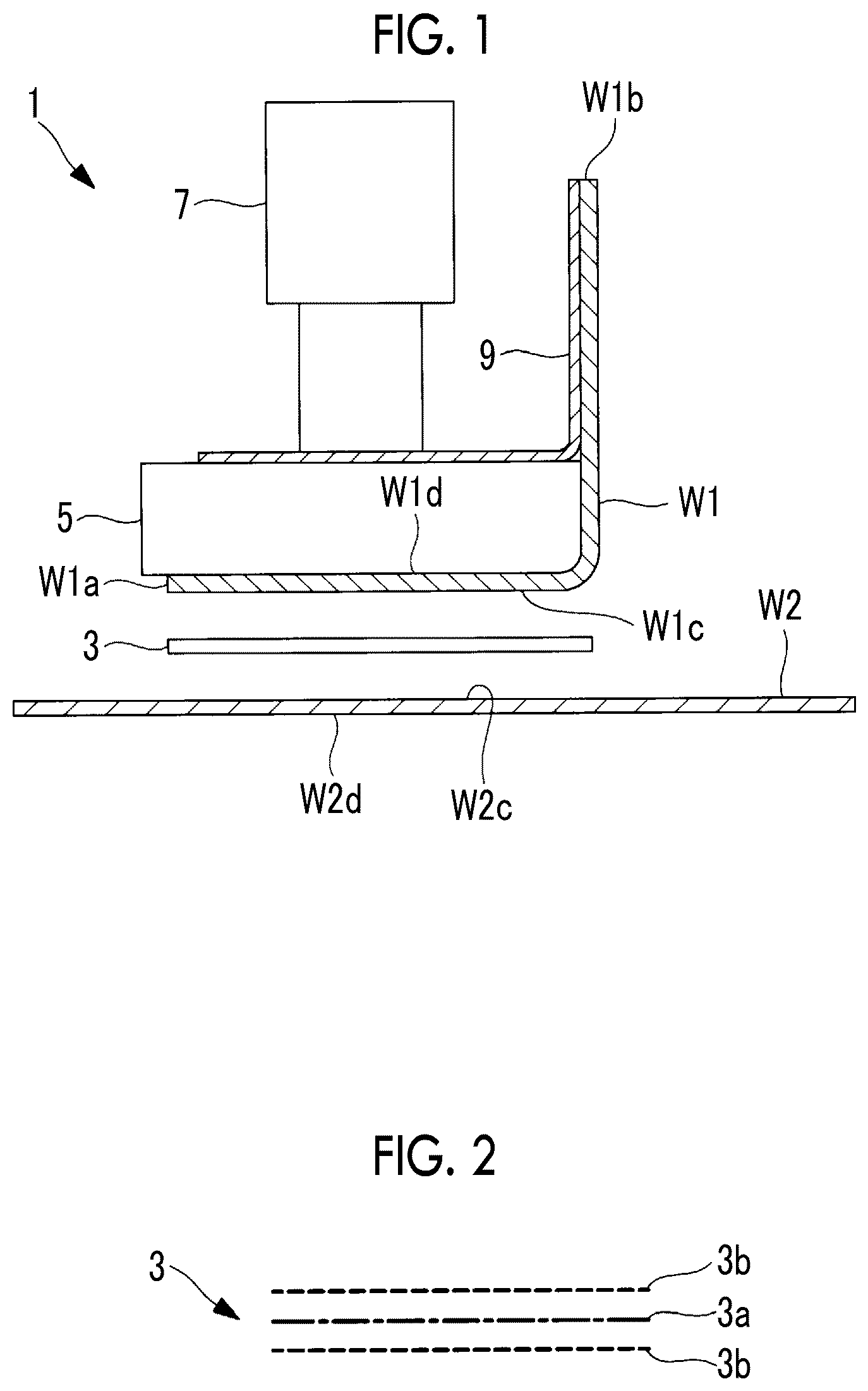
is a cross-sectional view showing a composite material bonding apparatus according to one aspect of the present disclosure.
is a longitudinal sectional view showing a layer configuration of a graphite heater.
is a plan view schematically showing the graphite heater.
is a cross-sectional view of the composite material bonding apparatus showing a state where the graphite heater is located at a retract position.
is a cross-sectional view of the composite material bonding apparatus showing a heating step using the graphite heater.
is a cross-sectional view of the composite material bonding apparatus showing a state where the graphite heater is retracted from an insertion position to the retract position.
is a cross-sectional view of the composite material bonding apparatus showing a state where pressurization is performed by a pressurizing plate.
is a cross-sectional view of the composite material bonding apparatus showing a state where the pressurizing plate is separated from a first composite member after bonding.
is a cross-sectional view of a composite material bonding apparatus according to a modification example.
DESCRIPTION OF EMBODIMENTS
Hereinafter, one embodiment according to the present disclosure will be described with reference to the drawings.
shows a schematic configuration of a composite material bonding apparatus 1 according to the present embodiment. The composite material bonding apparatus 1 is used to bond a first composite member W 1 and a second composite member W 2 to each other.
The composite members W 1 and W 2 are made of a composite material containing a resin and fibers such as carbon fibers. The composite members W 1 and W 2 can be used as, for example, a structural member for an aircraft, a ship, a vehicle, or the like. The composite members W 1 and W 2 have already been shaped and solidified.
A thermoplastic resin is preferably used for the composite members W 1 and W 2 . Examples of the composite material used for the composite members W 1 and W 2 include carbon fiber reinforced plastic (CFRP), glass fiber reinforced plastic (GFRP), aramid fiber reinforced plastic (AFRP), and the like.
The first composite member W 1 includes a bottom portion W 1 a and a side portion W 1 b standing from one side of the bottom portion W 1 a , and has an L-shaped cross section. The first composite member W 1 is a long member extending in a direction perpendicular to the paper surface of . A first bonding surface W 1 c that is a lower surface of the bottom portion W 1 a of the first composite member W 1 is bonded to a second bonding surface W 2 c that is an upper surface of the second composite member W 2 .
The second composite member W 2 is a long plate extending in the direction perpendicular to the paper surface of . A second back surface W 2 d that is a lower surface of the second composite member W 2 is installed on a table (not shown).
The composite material bonding apparatus 1 includes a graphite heater (sheet heater) 3 , a pressurizing plate (pressurizing means) 5 , a pressurizing actuator (pressurizing means) 7 , and a component holding stay (approaching and separating device) 9 .
As shown in , the graphite heater 3 has a structure in which a heat generating unit 3 a made of graphite and insulating layers 3 b are integrated with a front surface and a back surface of the heat generating unit 3 a sandwiched between the insulating layers 3 b . In the graphite heater 3 , a thickness of a main portion of the graphite heater 3 is, for example, 0.2 mm or more and 0.5 mm or less. However, although not shown, a frame, a rigid layer, or the like is appropriately provided to maintain a plate shape of the graphite heater 3 .
As shown in , the graphite heater 3 has a width substantially equal to or larger than or equal to a width (dimension in a horizontal direction in the same drawing) of the first bonding surface W 1 c . An area of a surface of the graphite heater 3 facing the bonding surfaces W 1 c and W 2 c is equal to or larger than or equal to an area of each of the bonding surfaces W 1 c and W 2 c . Accordingly, the entirety of both the bonding surfaces W 1 c and W 2 c can be uniformly heated in a short time.
The graphite heater 3 is connected to a graphite heater moving device (sheet heater moving device) (not shown). As shown in , the graphite heater moving device moves the graphite heater 3 between an insertion position between the first bonding surface W 1 c of the first composite member W 1 and the second bonding surface W 2 c of the second composite member W 2 and a retract position where the graphite heater 3 is retracted sideways from the insertion position.
As shown in , the heat generating unit 3 a of the graphite heater 3 is made of graphite. The graphite can be obtained, for example, by sintering polyimide films. A short heating time and a high reaching temperature can be realized by using graphite for the heat generating unit 3 a . For example, the heat generating unit 3 a can reach 1300° C. in a heating time of approximately 0.2 seconds.
The insulating layers 3 b are made of a material having electrical insulation, and for example, a resin having heat resistance, preferably a polyimide film is used. In addition, heat-resistant glass having heat resistance around 1000° C. may be used.
schematically shows the graphite heater 3 having a planar shape. Each of the insulating layers 3 b has a rectangular shape. In the heat generating unit 3 a , one wire-shaped unit is disposed in a meandering and folding manner, so as to be provided over the entire surface of the insulating layer 3 b having a rectangular shape. Both end portions of the heat generating unit 3 a are connected to a direct power supply 11 with variable current and/or voltage. The direct power supply is controlled by a control unit (not shown).
The control unit includes, for example, a central processing unit (CPU), a random access memory (RAM), a read only memory (ROM), a computer-readable storage medium, and the like. Furthermore, as one example, a series of processing for realizing various functions are stored in the storage medium or the like in the form of a program, and the CPU realizes the various functions by reading the program into the RAM or the like, and by executing information processing and arithmetic processing. Incidentally, a form in which the program is installed in the ROM or in other storage media in advance, a form in which the program is stored and provided in the computer-readable storage medium, a form in which the program is distributed via wired or wireless communication means, and the like may be applied. Examples of the computer-readable storage medium include magnetic disks, magneto-optical disks, CD-ROMs, DVD-ROMs, semiconductor memories, and the like.
The pressurizing plate 5 is, for example, a rectangular parallelepiped body made of metal, and is disposed such that a lower surface of the pressurizing plate 5 is in contact with a first back surface W 1 d that is an upper surface of the first composite member W 1 . The pressurizing actuator 7 is fixed to an upper portion of the pressurizing plate 5 . The pressurizing plate 5 has predetermined rigidity to uniformly transmit a pressurizing force of the pressurizing actuator 7 to the first composite member W 1 .
The pressurizing actuator 7 applies a predetermined pressurizing force to the first composite member W 1 via the pressurizing plate 5 according to a command from the control unit. As a driving force of the pressurizing actuator 7 , an electric motor, air pressure, hydraulic pressure, or the like is used.
The component holding stay 9 holds the first composite member W 1 , and causes the first composite member W 1 to approach and separate from the second composite member W 2 . The component holding stay 9 can hold the side portion W 1 b of the first composite member W 1 , for example, through vacuum suctioning. The pressurizing plate 5 and the pressurizing actuator 7 move up and down with operation of the component holding stay 9 .
Next, an operation of the composite material bonding apparatus 1 described above will be described.
First, as shown in , the first composite member W 1 is suctioned and held by the component holding stay 9 , and a predetermined spacing is provided between the first bonding surface W 1 c of the first composite member W 1 and the second bonding surface W 2 c of the second composite member W 2 with the first bonding surface W 1 c and the second bonding surface W 2 c facing each other. The pressurizing plate 5 is disposed to be in contact with an upper surface of the bottom portion W 1 a of the first composite member W 1 . At this time, the graphite heater 3 is located at the retract position where the graphite heater 3 is retracted sideways from the insertion position between the first bonding surface W 1 c and the second bonding surface W 2 c.
Then, the graphite heater 3 is moved in a lateral direction as indicated by arrow A 1 by the graphite heater moving device (not shown). Accordingly, the graphite heater 3 is located at the insertion position between the first bonding surface W 1 c and the second bonding surface W 2 c , as indicated by a chain double-dashed line. At this time, an upper surface and a lower surface of the graphite heater 3 are disposed at positions to be parallel to the first bonding surface W 1 c and to the second bonding surface W 2 c facing each other, and to cover entireties thereof.
In a state where the graphite heater 3 is located at the insertion position, the graphite heater 3 generates heat according to a command from the control unit. The heat to be generated from the graphite heater 3 is generated from both the upper and lower surfaces of the graphite heater 3 , and heats the first bonding surface W 1 c and the second bonding surface W 2 c facing each other, as indicated by arrows in (heating step). Accordingly, the resin located on the first bonding surface W 1 c and on the second bonding surface W 2 c are melted. Incidentally, heating may be performed by radiant heat in a state where the graphite heater 3 and each of the first bonding surface W 1 c and the second bonding surface W 2 c are spaced apart from each other as shown in , or heating may be performed by heat conduction in a state where the graphite heater 3 and each of the first bonding surface W 1 c and the second bonding surface W 2 c are in contact with each other.
A heating time and an output (current and/or voltage) of the graphite heater 3 are determined in advance according to the first composite member W 1 and to the second composite member W 2 to be heated, and are stored in, for example, a storage unit of the control unit.
When the heating by the graphite heater 3 is completed, as indicated by arrow A 2 of , the graphite heater 3 is moved from the insertion position to the retract position by the graphite heater moving device (retracting step).
Next, as shown in , while the first bonding surface W 1 c and the second bonding surface W 2 c are melted (namely, before solidification), the first composite member W 1 is lowered by the component holding stay 9 to bring the first bonding surface W 1 c and the second bonding surface W 2 c into contact with each other. Then, the pressurizing actuator 7 is operated according to a command from the control unit to press the pressurizing plate 5 downward and to hold the pressurizing plate 5 for a certain time while pressurizing the bottom portion W 1 a of the first composite member W 1 against the second composite member W 2 (bonding step). Accordingly, the first composite member W 1 and the second composite member W 2 are bonded to each other at the bonding surfaces W 1 c and W 2 c . Temperatures on the bonding surfaces W 1 c and W 2 c during the bonding step can be adjusted by heat dissipation using a heat capacity of the pressurizing plate 5 .
Thereafter, as shown in , after the pressurization by the pressurizing actuator 7 is released, the component holding stay 9 is raised with the suctioning of the first composite member W 1 by the component holding stay 9 released. Accordingly, the pressurizing plate 5 is separated from the first back surface W 1 d of the first composite member W 1 .
In such a manner, the predetermined step of bonding the first bonding surface W 1 c and the second bonding surface W 2 c to each other is completed. When another first bonding surface W 1 c and another second bonding surface W 2 c in a longitudinal direction of the first composite member W 1 and the second composite member W 2 are next bonded to each other, a transfer device that moves a relative position of the graphite heater 3 with respect to the first composite member W 1 and to the second composite member W 2 locates the graphite heater 3 at a different position corresponding to the first bonding surface W 1 c and to the second bonding surface W 2 c . In this case, the graphite heater 3 may be transferred, or the first composite member W 1 and the second composite member W 2 may be transferred.
The actions and effects of the present embodiment described above are as follows.
The first bonding surface W 1 c and the second bonding surface W 2 c can be uniformly heated simultaneously in a short time by locating the graphite heater 3 at the insertion position and by disposing the graphite heater 3 to be parallel to the first bonding surface W 1 c and to the second bonding surface W 2 c . Then, the first bonding surface W 1 c and the second bonding surface W 2 c can be brought into contact with and bonded to each other by retracting the graphite heater 3 to the retract position. In such a manner, the graphite heater 3 is moved between the insertion position and the retract position to heat the first bonding surface W 1 c and the second bonding surface W 2 c facing each other, and the first bonding surface W 1 c and the second bonding surface W 2 c can be immediately bonded to each other by retracting the graphite heater 3 after heating, so that cycle time can be shortened.
Since the first bonding surface W 1 c and the second bonding surface W 2 c are pressurized after the graphite heater 3 is retracted from the insertion position to the retract position, pressurization bonding can be immediately performed after the retraction of the graphite heater 3 , and cycle time can be shortened.
Since the pressurizing plate 5 is provided to be in contact with the first back surface W 1 d and/or with the second back surface W 2 d , the first bonding surface W 1 c and the second bonding surface W 2 c can be uniformly pressurized.
The graphite heater 3 is provided over one direction (left-right width direction in ) of the first bonding surface W 1 c and the second bonding surface W 2 c . Accordingly, heating can be performed at once in a range in the width direction of the first bonding surface W 1 c and the second bonding surface W 2 c.
Heating is performed using the graphite heater 3 . Namely, the graphite heater 3 is structured to include the heat generating unit 3 a made of graphite, and the insulating layers 3 b that sandwich and fix the heat generating unit 3 a . A short heating time and a high reaching temperature can be realized by using graphite for the heat generating unit 3 a.
The present embodiment described above can be modified as follows.
In the embodiment, the temperatures of the bonding surfaces W 1 c and W 2 c during the bonding step are adjusted by heat dissipation using the heat capacity of the pressurizing plate 5 , but as shown in , the pressurizing plate may be provided with a temperature adjustment unit 15 that performs heating and/or cooling. A temperature of the temperature adjustment unit 15 is controlled by the control unit. As the temperature adjustment unit 15 , an electric heater, a heat medium flow path through which a heating medium flows, or the like can be used for heating. In addition, a cooling element such as a Peltier element, a heat medium flow path through which a cooling medium flows, or the like can be used for cooling.
Since the temperature adjustment unit 15 is provided on the pressurizing plate 5 , the bonding surfaces W 1 c and W 2 c can be heated and/or cooled by the pressurizing plate 5 . Accordingly, a predetermined temperature suitable for bonding the bonding surfaces W 1 c and W 2 c to each other can be maintained during the bonding step, and proper bonding can be realized.
In addition, in the present embodiment, a case has been described in which the first composite member W 1 having an L-shaped cross section and the second composite member W 2 having a plate shape are bonded to each other, but the present disclosure is not limited to the shapes of the composite members, and can be widely used when composite members are connected to each other.
In addition, in the present embodiment, the graphite heater 3 is used, but an electric heater having a planar shape such as a stainless steel sheet heater may be used instead of the graphite heater 3 .
In addition, in the present embodiment, a configuration has been employed in which the first composite member W 1 is moved to approach and separate from the second composite member W 2 that is fixed, but the present disclosure is not limited to the configuration, and the first composite member W 1 may be fixed and the second composite member W 2 may be moved, or both the first composite member W 1 and the second composite member W 2 may be moved.
The composite material bonding apparatus and the composite material bonding method described above in each of the embodiments are understood, for example, as follows.
A composite material bonding apparatus ( 1 ) according to one aspect of the present disclosure includes: a sheet heater ( 3 ) having a planar shape; a sheet heater moving device that locates the sheet heater at an insertion position between a first bonding surface (W 1 c ) of a first composite member (W 1 ) and a second bonding surface (W 2 c ) of a second composite member (W 2 ) facing the first bonding surface, so as to be parallel to the first bonding surface and to the second bonding surface, and that retracts the sheet heater to a retract position to be retracted from the insertion position; and a control unit that controls the sheet heater moving device. The control unit causes the sheet heater to heat the first bonding surface and the second bonding surface at the insertion position, and then causes the sheet heater moving device to move the sheet heater to the retract position.
The first bonding surface and the second bonding surface can be uniformly heated simultaneously in a short time by locating the sheet heater at the insertion position and by disposing the sheet heater to be parallel to the first bonding surface and to the second bonding surface. Then, the first bonding surface and the second bonding surface can be brought into contact with and bonded to each other by retracting the sheet heater to the retract position. In such a manner, the sheet heater is moved between the insertion position and the retract position to heat the first bonding surface and the second bonding surface facing each other, and the first bonding surface and the second bonding surface can be immediately bonded to each other by retracting the sheet heater after heating, so that cycle time can be shortened.
The sheet heater and the first bonding surface and/or the second bonding surface may be in contact with or separated from each other at the insertion position.
Further, the composite material bonding apparatus according to one aspect of the present disclosure further includes pressurizing means ( 5 and 7 ) for pressurizing the first composite member and/or the second composite member in a direction in which the first bonding surface and the second bonding surface approach each other. After the sheet heater is retracted from the insertion position to the retract position, the control unit causes the pressurizing means to pressurize the first bonding surface and the second bonding surface.
Since the first bonding surface and the second bonding surface are pressurized after the sheet heater is retracted from the insertion position to the retract position, pressurization bonding can be immediately performed after the retraction of the sheet heater, and cycle time can be shortened.
Further, the composite material bonding apparatus according to one aspect of the present disclosure further includes an approaching and separating device ( 9 ) that causes the first bonding surface and the second bonding surface to approach and separate from each other. After the first bonding surface and the second bonding surface are pressurized by the pressurizing means, the control unit causes the approaching and separating device to separate the first bonding surface and the second bonding surface from each other.
Since the first bonding surface and the second bonding surface are separated from each other after pressurization, the process can quickly proceed to the next step.
Further, the composite material bonding apparatus according to one aspect of the present disclosure further includes a transfer device that moves a relative position of the sheet heater with respect to the first composite member and to the second composite member. After the first bonding surface and the second bonding surface are separated from each other by the approaching and separating device, the control unit causes the transfer device to move a relative position between the sheet heater and each of the first composite member and the second composite member, and causes the transfer device to move the sheet heater to the insertion position between the first bonding surface and the second bonding surface that is a position different from a position of the first bonding surface and the second bonding surface that are pressurized.
The transfer device moves the relative position between the sheet heater and each of the first composite member and the second composite member, and moves the sheet heater to the insertion position between the first bonding surface and the second bonding surface that is a position different from the position of the first bonding surface and the second bonding surface that are pressurized. Accordingly, the bonding surfaces can be sequentially bonded to each other at different positions.
Further, in the composite material bonding apparatus according to one aspect of the present disclosure, the pressurizing means includes a pressurizing plate ( 5 ) provided to be in contact with a first back surface of the first composite member that is a back surface side of the first bonding surface and/or with a second back surface of the second composite member that is a back surface side of the second bonding surface.
Since the pressurizing plate is provided to be in contact with the first back surface and/or with the second back surface, the first bonding surface and the second bonding surface can be uniformly pressurized.
Further, in the composite material bonding apparatus according to one aspect of the present disclosure, the pressurizing plate includes a temperature adjustment unit ( 15 ) that performs heating and/or cooling.
Since the temperature adjustment unit is provided on the pressurizing plate, the bonding surfaces can be heated and/or cooled by the pressurizing plate. Accordingly, a predetermined temperature can be maintained during pressurization, and proper bonding can be realized.
Further, in the composite material bonding apparatus according to one aspect of the present disclosure, the sheet heater is provided over a predetermined one direction of the first bonding surface and the second bonding surface.
The sheet heater is provided over one direction of the first bonding surface and the second bonding surface. Accordingly, heating can be uniformly performed in a range in the one direction of the first bonding surface and the second bonding surface. For example, when the first composite member and/or the second composite member is long, heating can be performed at once in a width direction (one direction).
The sheet heater includes a heat generating unit ( 3 a ) made of graphite, and insulating layers ( 3 b ) that sandwich and fix the heat generating unit.
The sheet heater is a graphite heater. Namely, the sheet heater is structured to include the heat generating unit made of graphite, and the insulating layers that sandwich and fix the heat generating unit. A short heating time and a high reaching temperature can be realized by using graphite for the heat generating unit. For example, the heat generating unit made of graphite can reach 1300° C. in a heating time of approximately 0.2 seconds.
A composite material bonding method according to one aspect of the present disclosure includes: a heating step of locating a sheet heater having a planar shape at an insertion position between a first bonding surface of a first composite member and a second bonding surface of a second composite member facing the first bonding surface, so as to be parallel to the first bonding surface and to the second bonding surface, and of causing the sheet heater to heat the first bonding surface and the second bonding surface; a retracting step of retracting the sheet heater to a retract position to be retracted from the insertion position; and a bonding step of causing the first bonding surface and the second bonding surface to approach each other, and of bonding the first bonding surface and the second bonding surface to each other.
REFERENCE SIGNS LIST
•
• 1 composite material bonding apparatus • 3 graphite heater (sheet heater) • 3 a heat generating unit • 3 b insulating layer • 5 pressurizing plate (pressurizing means) • 7 pressurizing actuator (pressurizing means) • 9 component holding stay (approaching and separating device) • 11 direct power supply • 15 temperature adjustment unit • W 1 first composite member • W 1 a bottom portion • W 1 b side portion • W 1 c first bonding surface • W 1 d first back surface • W 2 second composite member • W 2 c second bonding surface • W 2 d second back surface
Figures (5)
Citations
This patent cites (17)
- US3016085
- US3316687
- US4971639
- US5035045
- US5151149
- US5628859
- US11458720
- US2017/0368761
- US2018/0125155
- US106785232
- US2578381
- US3859321
- US2007-245458
- US4697909
- US2012-232564
- US2017-205960
- US2016/102292