Developer Cartridge and Image Forming Apparatus
Abstract
A developer cartridge includes a developing roller, a developer housing supporting the developing roller, and a toner storage unit including a first storage chamber capable of storing toner, and a second storage chamber storing the developer housing. The toner storage unit supports the developer housing such that the developer housing is movable with respect to the first storage chamber.
Claims (20)
1. A developer cartridge, comprising: a developing roller rotatable around a developer axis extending in a first direction; a developer housing supporting the developing roller; and a toner storage unit including a storage chamber capable of storing toner; wherein the developer housing is connected to the toner storage unit such that the developer housing is movable with respect to the storage chamber in a direction intersecting the first direction, and wherein the developer housing is moveable with respect to the storage chamber in the direction intersecting the first direction in a state in which the developer housing is located above the storage chamber.
11. An image forming apparatus, comprising; a body housing; a transfer unit; a drum cartridge including a photoconductive drum and located below the transfer unit in a state in which the drum cartridge is mounted on the body housing; a developer cartridge including: a developing roller rotatable around a developer axis extending in a first direction; a developer housing supporting the developing roller; and a toner storage unit including a storage chamber capable of storing toner, the developer housing being connected to the toner storage unit such that the developer housing is movable with respect to the storage chamber in a direction intersecting the first direction; a support frame supporting the toner storage unit in a state in which the developer cartridge is mounted on the body housing, wherein the developer housing is moveable with respect to the storage chamber in the direction intersecting the first direction in a state in which the developer housing is located above the storage chamber.
18. A developer cartridge, comprising: a developing roller rotatable around a developer axis extending in a first direction; a developer housing supporting the developing roller; and a toner storage unit including a storage chamber capable of storing toner, wherein the developer housing is connected to the toner storage unit such that the developer housing is moveable with respect to the storage chamber in a direction intersecting the first direction, and wherein an inlet opening of the developer housing and an opening of the storage chamber are communicated with each other, and the communication between the inlet opening of the developer housing and the opening of the storage chamber is kept during the relative movement of the developer housing with respect to the storage chamber in the direction intersecting the first direction.
Show 17 dependent claims
2. The developer cartridge according to claim 1 , further comprising a seal member configured to seal an area between the developer housing and the toner storage unit, wherein the toner storage unit includes an opening, wherein the developer housing includes an inlet opening that communicates with the opening of the toner storage unit, and wherein the developer housing is movable with respect to the storage chamber in the direction intersecting the first direction in a state in which the seal member is interposed between the developer housing and the toner storage unit.
3. The developer cartridge according to claim 2 , wherein the toner storage unit includes: a first support surface located on a first side with respect to the opening in the first direction and supporting a first end of the developer housing in the first direction; a second support surface located on a second side with respect to the opening in the first direction and supporting a second end of the developer housing in the first direction; a third support surface located on a first side with respect to the opening in a second direction and supporting a first end of the developer housing in the second direction; and a cover side wall located on a second side with respect to the opening in the second direction and covering a second end of the developer housing in the second direction.
4. The developer cartridge according to claim 3 , wherein the seal member is a first seal member and first seal member includes: a first seal portion sealing an area between the first end of the developer housing in the first direction and the first support surface; a second seal portion sealing an area between the second end of the developer housing in the first direction and the second support surface; and a third seal portion sealing an area between the first end of the developer housing in the second direction and the third support surface.
5. The developer cartridge according to claim 4 , further comprising a second seal member configured to seal an area between the second end of the developer housing in the second direction and the cover side wall.
6. The developer cartridge according to claim 5 , wherein the first seal member is a sponge, and wherein the second seal is a film.
7. The developer cartridge according to claim 1 , wherein the developer cartridge further comprises a shaft protruding in the first direction from an outer surface of the developer housing in the first direction, and wherein the toner storage unit further includes a tubular receiver configured to receive the shaft in the second storage chamber.
8. The developer cartridge according to claim 7 , wherein the developer housing is rotatable around the shaft with respect to the toner storage unit.
9. The developer cartridge according to claim 1 , wherein the toner storage unit further includes a shaft extending in the first direction such that the developer housing is connected to the toner storage unit.
10. The developer cartridge according to claim 1 , wherein the developer housing is connected to the toner storage unit such that the developer housing is movable together with the developing roller with respect to the storage chamber in the direction intersecting the first direction.
12. The image forming apparatus according to claim 11 , wherein the developer cartridge includes: a first engaging portion located at a first end of the developer housing in the first direction; a second engaging portion located at a second end of the developer housing in the first direction, wherein the drum cartridge includes: a first engaged portion located at a first end of the drum cartridge in the first direction and with which the first engaging portion engages in a state in which the drum cartridge and the developer cartridge are mounted on the body housing; and a second engaged portion located at a second end of the drum cartridge in the first direction and with which the second engaging portion engages in the state in which the drum cartridge and the developer cartridge are mounted on the body housing.
13. The image forming apparatus according to claim 11 , wherein the developer cartridge is movable between a first position at which the developing roller is in contact with the photoconductive drum and a second position at which the developing roller is spaced apart from the photoconductive drum in the state in which the drum cartridge and the developer cartridge are mounted on the body housing.
14. The image forming apparatus according to claim 11 , wherein the developing roller is movable with respect to the photoconductive drum in a state in which the developer housing is connected to the toner storage unit.
15. The image forming apparatus according to claim 11 , wherein the storage chamber is supported by the body frame of the image forming apparatus through the support frame in the state in which the developer cartridge is mounted on the body housing.
16. The image forming apparatus according to claim 11 , wherein the photoconductive drum is located above the toner storage unit in the state in which the drum cartridge and the developer cartridge are mounted on the body housing.
17. The image forming apparatus according to claim 11 , wherein the developer housing is connected to the toner storage unit such that the developer housing is movable together with the developing roller with respect to the storage chamber in the direction intersecting the first direction.
19. The developer cartridge according to claim 18 , further comprising a seal member configured to seal an area between the developer housing and the toner storage unit, and wherein the developer housing is moveable with respect to the storage chamber in the direction intersecting the first direction in a state in which the seal member is interposed between the developer housing and the toner storage unit.
20. The developer cartridge according to claim 18 , wherein the developer housing is connected to the toner storage unit such that the communication between the inlet opening of the developer housing and the opening of the storage chamber is kept during the movement of the developer housing together with the developing roller with respect to the storage chamber in the direction intersecting the first direction.
Full Description
Show full text →
REFERENCE TO RELATED APPLICATIONS
The present application is a continuation of U.S. patent application Ser. No. 18/050,649, filed Oct. 28, 2022, which claims priority from Japanese Patent Application No. 2021-179840, which was filed on Nov. 2, 2021, the disclosures of which are herein incorporated by reference in their entirety.
BACKGROUND ART
The following disclosure relates to a developer cartridge and an image forming apparatus.
There has been known a conventional image forming apparatus including an apparatus body having an opening, a cartridge and an intermediate transfer unit located above the cartridge. The cartridge includes, as one body, a photoconductive drum and a developing unit. The developing unit includes a developing roller. The cartridge is mountable on and removable from the apparatus body in an axis direction of the photoconductive drum through the opening.
DESCRIPTION
In the image forming apparatus, there is a case in which the cartridge is configured such that the cartridge is dividable into a drum cartridge including the photoconductive drum and a developer cartridge including the developing roller.
In the conventional image forming apparatus, however, the opening through which the cartridge passes is located on a first side with respect to the cartridge in the axis direction of the photoconductive drum. Accordingly, it is hard to provide a member supporting a first end of the drum cartridge in the axis direction of the photoconductive drum and supporting a first end of the developer cartridge in the axis direction of the photoconductive drum.
Accordingly, it is hard to secure degree of parallelization of the developing roller with respect to the photoconductive drum while the developing roller is configured to be movable with respect to the photoconductive drum.
An aspect of the disclosure relates to a developer cartridge and an image forming apparatus capable of securing degree of parallelization of a developing roller with respect to a photoconductive drum while the developing roller is movable with respect to the photoconductive drum.
In one aspect of the disclosure, a developer cartridge includes a developing roller, a developer housing supporting the developing roller, and a toner storage unit including a first storage chamber capable of storing toner, and a second storage chamber storing the developer housing. The toner storage unit supports the developer housing such that the developer housing is movable with respect to the first storage chamber.
In another aspect of the disclosure, an image forming apparatus includes a body housing, a transfer unit, a drum cartridge including a photoconductive drum and located below the transfer unit in a state in which the drum cartridge is mounted on the body housing, a developer cartridge including a developing roller, a developer housing supporting the developing roller, and a toner storage unit including a first storage chamber capable of storing toner and a second storage chamber storing the developer housing, the toner storage unit supporting the developer housing such that the developer housing is movable with respect to the first storage chamber, a support frame supporting the toner storage unit in a state in which the developer cartridge is mounted on the body housing.
The objects, features, advantages, and technical and industrial significance of the present disclosure will be better understood by reading the following detailed description of the embodiments, when considered in connection with the accompanying drawings, in which:
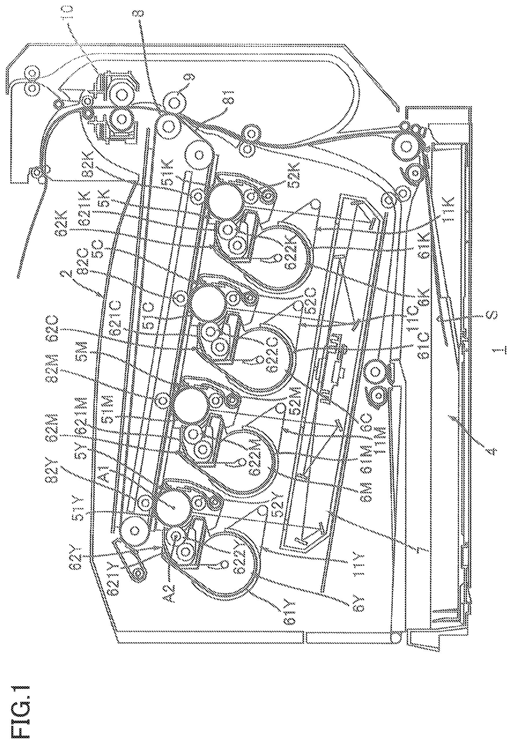
is a schematic view of a configuration of an image forming apparatus;
is a view for explaining mounting and removing of a drum cartridge and a developer cartridge illustrated in in a state in which a cover is positioned at a closed position;
is a state in which the cover illustrated in is positioned at an open position;
is a cross-sectional view of a central part of the developer cartridge illustrated in ;
is a disassembled perspective view of the developer cartridge illustrated in ;
is a view for explaining a movement of the developer cartridge in a state in which a support frame is positioned at a frame first position and the developer cartridge is positioned at a first position;
is a view for explaining of a movement of the developer cartridge in a state in which the support frame is positioned at a frame second position and the developer cartridge is positioned at a second position;
is a disassembled perspective view of a developer cartridge;
is a side view of the developer cartridge illustrated in ;
is a disassembled perspective view of a developer cartridge; and
is a side view of the developer cartridge illustrated in ;
is a disassembled perspective view of a developer cartridge; and
is a cross-sectional view of the developer cartridge illustrated in illustrating a cross section passing a developer rib and a toner rib.
OVERVIEW OF IMAGE FORMING APPARATUS
There will be described an overview of an image forming apparatus 1 in detail with reference to to .
It is noted that an up and down direction in the following description is an up and down direction defined when the image forming apparatus 1 is placed on a horizontal plane. Moreover, a first direction in the description of the image forming apparatus 1 is a first direction defined when a developer cartridge 6 Y is mounted on the image forming apparatus 1 .
As illustrated in , the image forming apparatus 1 includes a body housing 2 , a cover 3 (see ), a sheet tray 4 , a plurality of drum cartridges 5 Y, 5 M, 5 C, 5 K, a plurality of developer cartridges 6 Y, 6 M, 6 C, 6 K, an exposing unit 7 , a transfer unit 8 , a transfer roller 9 and a fixing unit 10 .
Body Housing
The body housing 2 accommodates the sheet tray 4 , the plurality of drum cartridges 5 Y, 5 M, 5 C, 5 K, the plurality of developer cartridges 6 Y, 6 M, 6 C, 6 K, the exposing unit 7 , the transfer unit 8 , the transfer roller 9 and the fixing unit 10 . The body housing 2 has an opening 21 (see ). The opening 21 is located at a first end of the body housing 2 in the first direction.
Cover
As illustrated in and , the cover 3 is movable between a closed position (see ) and an open position (see ). In a state in which the cover 3 is positioned at the closed position, the cover 3 closes the opening 21 . In a state in which the cover 3 is positioned at the open position, the opening 21 is open.
Sheet Tray
As illustrated in , the sheet tray 4 is capable of accommodating a sheet S. The sheet S in the sheet tray 4 is conveyed toward the transfer roller 9 .
Drum Cartridges
As illustrated in , in the state in which the cover 3 is positioned at the open position, each of the plurality of drum cartridges 5 Y, 5 M, 5 C, 5 K is mountable on and removable from the body housing 2 through the opening 21 . Each of the plurality of drum cartridges 5 Y, 5 M, 5 C, 5 K is mountable on and removable from the body housing 2 in the first direction. As illustrated in , in a state in which the plurality of drum cartridges 5 Y, 5 M, 5 C, 5 K are mounted on the body housing 2 , the plurality of drum cartridges 5 Y, 5 M, 5 C, 5 K are located below the transfer unit 8 . The drum cartridge 5 Y includes a photoconductive drum 51 Y and a charging unit 52 Y.
The photoconductive drum 51 Y extends in the first direction. The photoconductive drum 51 Y has a cylindrical shape. The photoconductive drum 51 Y is rotatable around a drum axis A 1 . The drum axis A 1 extends in the first direction.
The charging unit 52 Y charges the photoconductive drum 51 Y. In the present embodiment, the charging unit 52 Y is a charging roller. The charging unit 52 Y may be a scorotron type charging unit.
It is noted that each of the drum cartridges 5 M, 5 C, 5 K has the same configuration as the drum cartridge 5 Y. Accordingly, an explanation of the drum cartridges 5 M, 5 C, 5 K is dispensed with.
Developer Cartridges
As illustrated in , in the state in which the cover 3 is positioned at the open position, the plurality of developer cartridges 6 Y, 6 M, 6 C, 6 K are mountable on and removable from the body housing 2 through the opening 21 . As illustrated in , in a state in which the plurality of developer cartridges 6 Y, 6 M, 6 C, 6 K are mounted on the body housing 2 , the plurality of developer cartridges 6 Y, 6 M, 6 C, 6 K are located below the transfer unit 8 . The developer cartridge 6 Y includes a toner storage unit 61 Y and a developing unit 62 Y.
The toner storage unit 61 Y is capable of storing toner.
The developing unit 62 Y is supported by the toner storage unit 61 Y. The developing unit 62 Y includes a developer housing 621 Y and a developing roller 622 Y. In other words, the developer cartridge 6 Y includes the developer housing 621 Y and the developing roller 622 Y.
The developer housing 621 Y supports the developing roller 622 Y. The developer housing 621 Y is capable of receiving toner from the toner storage unit 61 Y. The developer housing 621 Y is capable of storing the toner from the toner storage unit 61 Y.
The developing roller 622 Y is capable of supplying the toner in the developer housing 621 Y to the photoconductive drum 51 Y. The developing roller 622 Y is in contact with the photoconductive drum 51 Y. The developing roller 622 Y may be capable of being spaced apart from the photoconductive drum 51 Y. The developing roller 622 Y extends in the first direction. The developing roller 622 Y is rotatable around a developer axis A 2 . The developer axis A 2 extends in the first direction.
It is noted that each of the developer cartridges 6 M, 6 C, 6 K has the same configuration as the developer cartridge 6 Y. Accordingly, an explanation of the developer cartridges 6 M, 6 C, 6 K is dispensed with.
Exposing Unit
In a state in which the plurality of drum cartridges 5 Y, 5 M, 5 C, 5 K are mounted on the image forming apparatus 1 , the exposing unit 7 is capable of exposing a circumferential surface of each of the photoconductive drums 51 Y, 51 M, 51 C, 51 K. In the present embodiment, the exposing unit 7 is a laser scanning unit.
Transfer Unit
In the state in which the plurality of drum cartridges 5 Y, 5 M, 5 C, 5 K are mounted on the image forming apparatus 1 , the transfer unit 8 is located above the plurality of drum cartridges 5 Y, 5 M, 5 C, 5 K. The transfer unit 8 includes an intermediate belt 81 and transfer rollers 82 Y, 82 M, 82 C, 82 K.
In the state in which the plurality of drum cartridges 5 Y, 5 M, 5 C, 5 K are mounted on the image forming apparatus 1 , the intermediate belt 81 is in contact with each of the photoconductive drums 51 Y, 51 M, 51 C, 51 K.
The transfer roller 82 Y transfers toner on the photoconductive drum 51 Y to the intermediate belt 81 . The transfer roller 82 M transfers toner on the photoconductive drum 51 M to the intermediate belt 81 . The transfer roller 82 C transfers toner on the photoconductive drum 51 C to the intermediate belt 81 . The transfer roller 82 K transfers toner on the photoconductive drum 51 K to the intermediate belt 81 .
Transfer Roller
The transfer roller 9 transfers the toner on the intermediate belt 81 to the sheet S. More specifically, the sheet S conveyed from the sheet tray 4 toward the transfer roller 9 is conveyed to the fixing unit 10 between the transfer roller 9 and the intermediate belt 81 . At this time, the transfer roller 9 transfers the toner on the intermediate belt 81 to the sheet S.
Fixing Unit
The fixing unit 10 heats and presses the sheet S to which the toner is transferred, and causes the toner to be fixed onto the sheet S. The sheet S having passed through the fixing unit 10 is discharged to an upper surface of the body housing 2 .
Details of Developer Cartridge
Next, there will be described the developer cartridge 6 Y in detail with reference to to . As illustrated in and , the developer cartridge 6 Y includes a first seal member 63 , a second seal member 64 , an agitator 65 (see ) in addition to the toner storage unit 61 Y and the developing unit 62 Y.
Details of Toner Storage Unit
As illustrated in , the toner storage unit 61 Y extends in the first direction. The toner storage unit 61 Y includes a first storage chamber 611 and a second storage chamber 612 .
First Storage Chamber
The first storage chamber 611 is capable of storing toner. The first storage chamber 611 extends in the first direction. The first storage chamber 611 has a cylindrical shape. As illustrated in , in a state in which the developer cartridge 6 Y is mounted on the image forming apparatus 1 , an upper surface T of the toner in the first storage chamber 611 indicating an amount of the toner in the first storage chamber 611 is located at a position lower than the developer housing 621 Y. In other words, in the state in which the developer cartridge 6 Y is mounted on the image forming apparatus 1 , the upper surface T of the toner in the toner storage unit 61 Y indicating the amount of the toner in the toner storage unit 61 Y is located at the position lower than the developer housing 621 Y.
As illustrated in , the first storage chamber 611 includes an opening 6111 , a first support surface 6112 A, a second support surface 6112 B (see ), a third support surface 6112 C, a fourth support surface 6112 D and a fifth support surface 6112 E (see ). In other words, the toner storage unit 61 Y includes the opening 6111 , the first support surface 6112 A, the second support surface 6112 B and the third support surface 6112 C.
The opening 6111 allows the first storage chamber 611 and the second storage chamber 612 to be communicated with each other. The opening 6111 is located at a boundary position between the first storage chamber 611 and the second storage chamber 612 . In the state in which the developer cartridge 6 Y is mounted on the image forming apparatus 1 , the opening 6111 is located at an upper end of the first storage chamber 611 . The opening 6111 extends in the first direction. The opening 6111 communicates with an inlet opening 6211 of the developer housing 621 Y (see ). The inlet opening 6211 will be described below. The toner is permitted to pass through the opening 6111 from the toner storage unit 61 Y to the developer housing 621 Y.
The first support surface 6112 A is located on a first side with respect to the opening 6111 in the first direction. The first support surface 6112 A supports a first end of the developer housing 621 Y in the first direction. The first support surface 6112 A has a width in the first direction and extends in a second direction. The second direction intersects the first direction. It is preferable that the second direction is orthogonal to the first direction.
The second support surface 6112 B illustrated in is located on a second side with respect to the opening 6111 in the first direction (see ). In other words, the second support surface 6112 B is located on an opposite side of the first support surface 6112 A with respect to the opening 6111 in the first direction. The second support surface 6112 B supports a second end of the developer housing 621 Y in the first direction. As similar to the first support surface 6112 A, the second support surface 6112 B has a width in the first direction and extends in the second direction.
The third support surface 6112 C is located on a first side with respect to the opening 6111 in the second direction. The third support surface 6112 C supports a first end of the developer housing 621 Y in the second direction. The third support surface 6112 C has a width in the second direction and extends in the first direction. A first end of the third support surface 6112 C in the first direction continues to the first support surface 6112 A. A second end of the third support surface 6112 C in the first direction continues to the second support surface 6112 B.
The fourth support surface 6112 D is located on the first side with respect to the opening 6111 in the first direction. The fourth support surface 6112 D supports the first end of the developer housing 621 Y in the first direction together with the first support surface 6112 A. The fourth support surface 6112 D has a width in the first direction and extends in a third direction. The third direction intersects the first direction and the second direction. It is preferable that the third direction is orthogonal to the first direction and intersects the second direction. In the state in which the developer cartridge 6 Y is mounted on the image forming apparatus 1 , the third direction is an up and down direction. A first end of the fourth support surface 6112 D in the third direction continues to the first support surface 6112 A. A second end of the fourth support surface 6112 D in the third direction continues to an inner surface of a cover side wall 6122 .
The fifth support surface 6112 E illustrated in is located on the second side with respect to the opening 6111 in the first direction. The fifth support surface 6112 E supports the second end of the developer housing 621 Y in the first direction together with the second support surface 6112 B. As similar to the fourth support surface 6112 D (see ), the fifth support surface 6112 E has a width in the first direction and extends in the third direction. A first end of the fifth support surface 6112 E in the third direction continues to the second support surface 6112 B. A second end of the fifth support surface 6112 E in the third direction continues to the inner surface of the cover side wall 6122 .
Second Storage Chamber
The second storage chamber 612 stores the developer housing 621 Y. The second storage chamber 612 is located on a second side with respect to the first storage chamber 611 in the third direction. In the state in which the developer cartridge 6 Y is mounted on the image forming apparatus 1 , the second storage chamber 612 is located above the first storage chamber 611 .
As illustrated in , the second storage chamber 612 includes two support side walls 6121 A, 6121 B, the cover side wall 6122 and two receiving portions 6123 A, 6123 B. In other words, the toner storage unit 61 Y includes the cover side wall 6122 and the two receiving portions 6123 A, 6123 B.
The support side wall 6121 A is located on a first end of the toner storage unit 61 Y in the first direction. The support side wall 6121 A is located on a first side with respect to the first support surface 6112 A in the first direction. In other words, the support side wall 6121 A is located on an outer side with respect to the first support surface 6112 A in the first direction. The support side wall 6121 A is located on an opposite side of the opening 6111 in the first direction with respect to the first support surface 6112 A. The support side wall 6121 A extends in the second direction and the third direction. The support side wall 6121 A supports the first end of the developer housing 621 Y in the first direction. The support side wall 6121 A has a hole 61211 A and a hole 61212 A. In other words, the second storage chamber 612 of the toner storage unit 61 Y has the hole 61212 A.
The hole 61211 A is located at a first end of the support side wall 6121 A in the second direction. The hole 61212 A is located on an opposite side of the cover side wall 6122 in the second direction with respect to the opening 6111 . The hole 61211 A has a circular shape. A shaft 623 A of the developing unit 62 Y is fitted into the hole 61211 A. The shaft 623 A will be described below.
The hole 61212 A is spaced apart from the hole 61211 A. In the present embodiment, the hole 61212 A is located between the hole 61211 A and the cover side wall 6122 in the second direction. The hole 61212 A extends in a direction intersecting the first direction. More specifically, the hole 61212 A extends in a circumferential direction of a circle centered around the hole 61211 A. A protrusion 624 A of the developing unit 62 Y is fitted into the hole 61212 A. The protrusion 624 A will be described below.
The support side wall 6121 B is located at a second end of the toner storage unit 61 Y in the first direction. The support side wall 6121 B is located on a second side with respect to the second support surface 6112 B (see ) in the first direction. In other words, the support side wall 6121 B is located on an outer side with respect to the second support surface 6112 B in the first direction. The support side wall 6121 B is located on an opposite side of the opening 6111 in the first direction with respect to the second support surface 6112 B. The support side wall 6121 B extends in the second direction and the third direction. The support side wall 6121 B supports the second end of the developer housing 621 Y in the first direction. The support side wall 6121 B has a hole 61211 B and a hole 61212 B.
The hole 61211 B is located at a first end of the support side wall 6121 B in the second direction. The hole 61212 B is located on an opposite side of the cover side wall 6122 in the second direction with respect to the opening 6111 . The hole 61211 B has a circular shape. A shaft 623 B of the developing unit 62 Y is fitted into the hole 61211 B. The shaft 623 B will be described below.
The hole 61212 B is spaced apart from the hole 61211 B. In the present embodiment, the hole 61212 B is located between the hole 61211 B and the cover side wall 6122 in the second direction. The hole 61212 B extends in a direction in which the hole 61212 A extends. That is, the hole 61212 B extends in a circumferential direction of a circle centered around the hole 61211 B. A protrusion 624 B of the developing unit 62 Y is fitted into the hole 61212 B. The protrusion 624 B will be described below.
The cover side wall 6122 is located on the second side with respect to the opening 6111 in the second direction. The cover side wall 6122 covers the second end of the developer housing 621 Y in the second direction. The cover side wall 6122 extends in the first direction. The cover side wall 6122 is inclined with respect to the third direction. As illustrated in , the cover side wall 6122 is inclined so as to be apart from the developer housing 621 Y in the second direction as approaching the first storage chamber 611 in the third direction. As illustrated in , a first end of the cover side wall 6122 in the first direction is connected to the support side wall 6121 A. A second end of the cover side wall 6122 in the first direction is connected to the support side wall 6121 B.
The receiving portion 6123 A is located on an outer side with respect to the support side wall 6121 A in the first direction. In other words, the receiving portion 6123 A is located on an opposite side of the opening 6111 in the first direction with respect to the support side wall 6121 A. In the present embodiment, the receiving portion 6123 A protrudes outwardly, in the first direction, from an outer surface of the support side wall 6121 A in the first direction. In other words, the receiving portion 6123 A protrudes outwardly, in the first direction, from an outer surface of the second storage chamber 612 in the first direction. It is noted that the receiving portion 6123 A may be attached to the outer surface of the support side wall 6121 A. The receiving portion 6123 A has a tubular shape. In the present embodiment, the receiving portion 6123 A has a cylindrical shape. An inner space of the receiving portion 6123 A communicates with the hole 61211 A. The shaft 623 A is fitted into the receiving portion 6123 A. The receiving portion 6123 A receives the shaft 623 A.
The receiving portion 6123 B is located on an outer side with respect to the support side wall 6121 B in the first direction. In other words, the receiving portion 6123 B is located on an opposite side of the opening 6111 in the first direction with respect to the support side wall 6121 B. In the present embodiment, the receiving portion 6123 B protrudes outwardly, in the first direction, from an outer surface of the support side wall 6121 B in the first direction. In other words, the receiving portion 6123 B protrudes outwardly, in the first direction, from the outer surface of the second storage chamber 612 in the first direction. It is noted that the receiving portion 6123 B may be attached to the outer surface of the support side wall 6121 B. The receiving portion 6123 B has a tubular shape. In the present embodiment, the receiving portion 6123 B has a cylindrical shape. An inner space of the receiving portion 6123 B communicates with the hole 61211 B. The shaft 623 B is fitted into the receiving portion 6123 B. The receiving portion 6123 B receives the shaft 623 B.
Details of Developing Unit
The developing unit 62 Y includes the two shafts 623 A, 623 B and the two protrusions 624 A, 624 B in addition to the developer housing 621 Y and the developing roller 622 Y. In other words, the developer cartridge 6 Y includes the two shafts 623 A, 623 B. In the present embodiment, the shaft 623 A functions as a first engaging portion, and the shaft 623 B functions as a second engaging portion.
Details of Developer Housing
The developer housing 621 Y extends in the first direction. The developer housing 621 Y has a tubular shape. As illustrated in , the second end of the developer housing 621 Y in the second direction is opposed to the cover side wall 6122 . The developer housing 621 Y has the inlet opening 6211 .
The inlet opening 6211 is capable of receiving toner from the toner storage unit 61 Y. The toner from the toner storage unit 61 Y enters into the developer housing 621 Y passing between the cover side wall 6122 and the developer housing 621 Y, and through the inlet opening 6211 . The inlet opening 6211 is located at the second end of the developer housing 621 Y in the second direction.
Shaft
As illustrated in , the shaft 623 A is located at the first end of the developer housing 621 Y in the first direction. The shaft 623 A protrudes outwardly, in the first direction, from a first side surface of the developer housing 621 Y in the first direction. It is noted that the shaft 623 A may be attached to the first side surface of the developer housing 621 Y in the first direction. The shaft 623 A is spaced apart from the developer axis A 2 . The shaft 623 A has a column shape. The shaft 623 A is fitted into the receiving portion 6123 A of the toner storage unit 61 Y through the hole 61211 A of the toner storage unit 61 Y.
The shaft 623 B is located at the second end of the developer housing 621 Y in the first direction. The shaft 623 B protrudes outwardly, in the first direction, from a second side surface of the developer housing 621 Y in the first direction. It is noted that the shaft 623 B may be attached to the second side surface of the developer housing 621 Y in the first direction. The shaft 623 B is spaced apart from the developer axis A 2 . The shaft 623 B has a column shape. The shaft 623 B is fitted into the receiving portion 6123 B of the toner storage unit 61 Y through the hole 61211 B of the toner storage unit 61 Y.
Protrusion
The protrusion 624 A protrudes outwardly, in the first direction, from the first side surface of the developer housing 621 Y in the first direction. It is noted that the protrusion 624 A may be attached to the first side surface of the developer housing 621 Y in the first direction. The protrusion 624 A is spaced apart from the shaft 623 A. The protrusion 624 A has a cylindrical shape. In the present embodiment, the protrusion 624 A receives a shaft of the developing roller 622 Y. The protrusion 624 A is fitted into the hole 61212 A of the toner storage unit 61 Y.
The protrusion 624 B protrudes outwardly, in the first direction, from the second side surface of the developer housing 621 Y in the first direction. It is noted that the protrusion 624 B may be attached to the second side surface of the developer housing 621 Y of the first direction. The protrusion 624 B is spaced apart from the shaft 623 B. The protrusion 624 B has a cylindrical shape. In the present embodiment, the protrusion 624 B receives the shaft of the developing roller 622 Y. The protrusion 624 B is fitted into the hole 61212 B of the toner storage unit 61 Y.
When the shaft 623 A is fitted into the receiving portion 6123 A, the shaft 623 B is fitted into the receiving portion 6123 B, the protrusion 624 A is fitted into the hole 61212 A and the protrusion 624 B is fitted into the hole 61212 B, the developer housing 621 Y is supported by the toner storage unit 61 Y so as to be movable. The developer housing 621 Y is movable with respect to the toner storage unit 61 Y in a direction in which each of the hole 61212 A and the hole 61212 B extends. In the present embodiment, the developer housing 621 Y is rotatable around the shaft 623 A and the shaft 623 B with respect to the toner storage unit 61 Y.
First Seal Member
As illustrated in , the first seal member 63 seals an area between the toner storage unit 61 Y and the developer housing 621 Y. The first seal member 63 is elastically deformable in accordance with a movement of the developer housing 621 Y. The first seal member 63 is, for example, a sponge. As illustrated in , the first seal member 63 includes a first seal portion 63 A, a second seal portion 63 B, a third seal portion 63 C, a fourth seal portion 63 D and a fifth seal portion 63 E.
The first seal portion 63 A is located at a first end of the first seal member 63 in the first direction. The first seal portion 63 A has a width in the first direction and extends in the second direction. The first seal portion 63 A is located between the first end of the developer housing 621 Y in the first direction and the first support surface 6112 A of the toner storage unit 61 Y. The first seal portion 63 A is in contact with the first end of the developer housing 621 Y in the first direction and the first support surface 6112 A of the toner storage unit 61 Y. The first seal portion 63 A seals an area between the first end of the developer housing 621 Y and the first support surface 6112 A in the first direction.
The second seal portion 63 B is located at a second end of the first seal member 63 in the first direction. The second seal portion 63 B is spaced apart from the first seal portion 63 A in the first direction. The second seal portion 63 B has a width in the first direction and extends in the second direction. The second seal portion 63 B is located between the second end of the developer housing 621 Y in the first direction and the second support surface 6112 B of the toner storage unit 61 Y (see ). The second seal portion 63 B is in contact with the second end of the developer housing 621 Y in the first direction and the second support surface 6112 B of the toner storage unit 61 Y. The second seal portion 63 B seals an area between the second end of the developer housing 621 Y in the first direction and the second support surface 6112 B.
The third seal portion 63 C is located between the first seal portion 63 A and the second seal portion 63 B in the first direction. The third seal portion 63 C has a width in the second direction and extends in the first direction. A first end of the third seal portion 63 C in the first direction continues to the first seal portion 63 A. A second end of the third seal portion 63 C in the first direction continues to the second seal portion 63 B. The third seal portion 63 C is located between the first end of the developer housing 621 Y in the second direction and the third support surface 6112 C of the toner storage unit 61 Y. The third seal portion 63 C is in contact with the first end of the developer housing 621 Y in the second direction and the third support surface 6112 C of the toner storage unit 61 Y. The third seal portion 63 C seals an area between the first end of the developer housing 621 Y in the second direction and the third support surface 6112 C.
The fourth seal portion 63 D is located at the first end of the first seal member 63 in the first direction. The fourth seal portion 63 D is located at a second end of the first seal portion 63 A in the second direction. The fourth seal portion 63 D has a width in the first direction. The fourth seal portion 63 D extends, in the third direction, from the second end of the first seal portion 63 A in the second direction. The fourth seal portion 63 D is located between the first end of the developer housing 621 Y the first direction and the fourth support surface 6112 D of the toner storage unit 61 Y. The fourth seal portion 63 D is in contact with the first end of the developer housing 621 Y in the first direction and the fourth support surface 6112 D of the toner storage unit 61 Y. The fourth seal portion 63 D seals an area between the first end of the developer housing 621 Y in the first direction and the fourth support surface 6112 D.
The fifth seal portion 63 E is located at the second end of the first seal member 63 in the first direction. The fifth seal portion 63 E is located at a second end of the second seal portion 63 B in the second direction. The fifth seal portion 63 E has a width in the first direction. The fifth seal portion 63 E extends, in the third direction, from the second end of the second seal portion 63 B in the first direction. The fifth seal portion 63 E is located between the second end of the developer housing 621 Y in the first direction and the fifth support surface 6112 E of the toner storage unit 61 Y (see ). The fifth seal portion 63 E is in contact with the second end of the developer housing 621 Y in the first direction and the fifth support surface 6112 E of the toner storage unit 61 Y. The fifth seal portion 63 E seals an area between the second end of the developer housing 621 Y in the first direction and the fifth support surface 6112 E.
Second Seal Member
As illustrated in , the second seal member 64 is located between the second end of the developer housing 621 Y in the second direction and the cover side wall 6122 of the toner storage unit 61 Y. As illustrated in , the second seal member 64 extends in the first direction. The second seal member 64 extends in the first direction from the fourth seal portion 63 D to the fifth seal portion 63 E. The second seal member 64 is adhered to the second end of the developer housing 621 Y in the second direction and in contact with the cover side wall 6122 of the toner storage unit 61 Y. The second seal member 64 seals an area between the second end of the developer housing 621 Y in the second direction and the cover side wall 6122 . The second seal member 64 is, for example, a film. The second seal member 64 may be a sponge.
Agitator
As illustrated in , the agitator 65 is located in the first storage chamber 611 of the toner storage unit 61 Y. The agitator 65 is capable of agitating the toner in the first storage chamber 611 of the toner storage unit 61 Y. The agitator 65 is capable of conveying the toner in the toner storage unit 61 Y toward the inlet opening 6211 of the developer housing 621 Y. The agitator 65 is rotatable around an agitator axis A 3 . The agitator axis A 3 extends in the first direction. In the state in which the developer cartridge 6 Y is mounted on the image forming apparatus 1 , the agitator axis A 3 is located at a position lower than the developer housing 621 Y. The agitator 65 includes a shaft 651 and a blade 652 .
The shaft 651 extends in the first direction along the agitator axis A 3 .
The blade 652 extends from the shaft 651 . The blade 652 is rotatable together with the shaft 651 . The blade 652 is capable of conveying the toner in the toner storage unit 61 Y toward the inlet opening 6211 . An edge of the blade 652 is reachable to the inlet opening 6211 .
Details of Drum Cartridge There will be described the drum cartridge 5 Y in detail with reference to , and .
As illustrated in , the drum cartridge 5 Y includes two side plates 53 A, 53 B in addition to the photoconductive drum 51 Y and the charging unit 52 Y.
The side plate 53 A is located at a first end of the drum cartridge 5 Y in the first direction. The side plate 53 A supports a first end of the photoconductive drum 51 Y in the first direction. As illustrated in , the side plate 53 A includes a first engaged portion 531 A. In other words, the drum cartridge 5 Y includes the first engaged portion 531 A.
The first engaged portion 531 A is located at the first end of the drum cartridge 5 Y in the first direction. The first engaged portion 531 A is a groove. In a state in which the developer cartridge 6 Y and the drum cartridge 5 Y are mounted on the image forming apparatus 1 , the receiving portion 6123 A of the toner storage unit 61 Y is fitted into the first engaged portion 531 A. As a result of this, in the state in which the developer cartridge 6 Y and the drum cartridge 5 Y are mounted on the image forming apparatus 1 , the shaft 623 A of the developing unit 62 Y (see ) engages with the first engaged portion 531 A via the receiving portion 6123 A.
As illustrated in , the side plate 53 B is spaced apart from the side plate 53 A in the first direction. The side plate 53 B is located at a second end of the drum cartridge 5 Y in the first direction. The side plate 53 B supports a second end of the photoconductive drum 51 Y in the first direction. As illustrated in , the side plate 53 B includes a second engaged portion 531 B. In other words, the drum cartridge 5 Y includes the second engaged portion 531 B.
The second engaged portion 531 B is located at the second end of the drum cartridge 5 Y in the first direction. The second engaged portion 531 B is a groove. In the state in which the developer cartridge 6 Y and the drum cartridge 5 Y are mounted on the image forming apparatus 1 , the receiving portion 6123 B of the toner storage unit 61 Y is fitted into the second engaged portion 531 B. As a result of this, in the state in which the developer cartridge 6 Y and the drum cartridge 5 Y are mounted on the image forming apparatus 1 , the shaft 623 B of the developing unit 62 Y (see ) engages with the second engaged portion 531 B via the receiving portion 6123 B.
Details of Image Forming Apparatus
There will be described next the image forming apparatus 1 in detail with reference to and .
As illustrated in , the image forming apparatus 1 further includes a plurality of support frames 11 Y, 11 M, 11 C, 11 K.
The support frame 11 Y is located in the body housing 2 . In the state in which the developer cartridge 6 Y is mounted on the image forming apparatus 1 , the support frame 11 Y supports the toner storage unit 61 Y.
As illustrated in and , in a state in which the support frame 11 Y supports the toner storage unit 61 Y, the support frame 11 Y is movable between a frame first position (see ) and a frame second position (see ). In the present embodiment, the support frame 11 Y is pivotable around an axis A 4 between the frame first position and the frame second position.
As illustrated in , in a state in which the support frame 11 Y is positioned at the frame first position, the support frame 11 Y positions the developer cartridge 6 Y at a first position. In a state in which the developer cartridge 6 Y is positioned at the first position, the developing roller 622 Y (see ) is in contact with the photoconductive drum 51 Y (see ).
As illustrated in , in a state in which the support frame 11 Y is positioned at the frame second position, the support frame 11 Y positions the developer cartridge 6 Y at a second position. In a state in which the developer cartridge 6 Y is positioned at the second position, the developing roller 622 Y is spaced apart from the photoconductive drum 51 Y.
That is, in the state in which the drum cartridge 5 Y and the developer cartridge 6 Y are mounted on the image forming apparatus 1 , the developer cartridge 6 Y is movable between the first position and the second position.
As illustrated in , the support frame 11 Y includes a supporting portion 111 , an axis portion 112 and an arm portion 113 .
In the state in which the developer cartridge 6 Y is mounted on the image forming apparatus 1 , the supporting portion 111 supports the toner storage unit 61 Y. The supporting portion 111 extends in the first direction. The supporting portion 111 has an arc shape curved along an outer surface of the toner storage unit 61 Y.
The axis portion 112 is spaced apart from the supporting portion 111 . The axis portion 112 extends in the first direction along the axis A 4 .
The arm portion 113 connects the supporting portion 111 with the axis portion 112 .
Effects
According to the developer cartridge 6 Y, as illustrated in and , the toner storage unit 61 Y includes the first storage chamber 611 capable of storing toner and the second storage chamber 612 storing the developer housing 621 Y. And, the developer housing 621 Y is supported by the toner storage unit 61 Y so as to be movable. Accordingly, the developing roller 622 Y is movable with respect to the toner storage unit 61 Y.
And, as illustrated in , in a case where the developer cartridge 6 Y is mounted on the image forming apparatus 1 and the toner storage unit 61 Y of the developer cartridge 6 Y is supported by the image forming apparatus 1 , the developing roller 622 Y movable with respect to the toner storage unit 61 Y is in contact with the photoconductive drum 51 Y. Accordingly, the developing roller 622 Y becomes movable with respect to the photoconductive drum 51 Y.
Moreover, since the toner storage unit 61 Y can support the developer housing 621 Y, it is possible to secure degree of parallelization of the developing roller 622 Y with respect to the photoconductive drum 51 Y.
Accordingly, it is possible to secure the degree of parallelization of the developing roller 622 Y with respect to the photoconductive drum 51 Y while the developing roller 622 Y is movable with respect to the photoconductive drum 51 Y.
As illustrated in , the image forming apparatus 1 includes the support frame 11 Y. In the state in which the developer cartridge 6 Y is mounted on the image forming apparatus 1 , the support frame 11 Y supports the toner storage unit 61 Y of the developer cartridge 6 Y.
Accordingly, it is possible to bring the developing roller 622 Y into contact with the photoconductive drum 51 Y in a state in which the developing roller 622 Y is movable with respect to the toner storage unit 61 Y. Moreover, since the developer housing 621 Y is supported by the toner storage unit 61 Y, it is possible to secure the degree of parallelization of the developing roller 622 Y with respect to the photoconductive drum 51 Y.
Accordingly, it is possible to secure the degree of parallelization of the developing roller 622 Y with respect to the photoconductive drum 51 Y while the developing roller 622 Y is movable with respect to the photoconductive drum 51 Y.
According to the image forming apparatus 1 , as illustrated in , in a state in which the drum cartridge 5 Y and the developer cartridge 6 Y are mounted on the body housing 2 , the shaft 623 A of the developing unit 62 Y engages with the first engaged portion 531 A of the drum cartridge 5 Y via the receiving portion 6123 A. Moreover, in the state in which the drum cartridge 5 Y and the developer cartridge 6 Y are mounted on the body housing 2 , the shaft 623 B of the developing unit 62 Y (see ) engages with the second engaged portion 531 B of the drum cartridge 5 Y (see ) via the receiving portion 6123 B (see ).
As a result of this, in the state in which the drum cartridge 5 Y and the developer cartridge 6 Y are mounted on the body housing 2 , it is possible to support ends of the developer housing 621 Y in the first direction by the drum cartridge 5 Y.
Accordingly, it is possible to secure the degree of the parallelization of the developing roller 622 Y with respect to the photoconductive drum 51 Y more.
While the disclosure has been described in conjunction with various example structures outlined above and illustrated in the figures, various alternatives, modifications, variations, improvements, and/or substantial equivalents, whether known or that may be presently unforeseen, may become apparent to those having at least ordinary skill in the art. Accordingly, the example embodiments of the disclosure, as set forth above, are intended to be illustrative of the disclosure, and not limiting the disclosure. Various changes may be made without departing from the spirit and scope of the disclosure. Therefore, the disclosure is intended to embrace all known or later developed alternatives, modifications, variations, improvements, and/or substantial equivalents. Some specific examples of potential alternatives, modifications, or variations in the described disclosure are provided below.
Modifications
There will be described modifications of the developer cartridge 6 Y with reference to to . It is noted that the same reference numerals as used in the above-described embodiment are used to designate the corresponding elements of the modifications, and an explanation of which is dispensed with or simplified.
As illustrated in , the toner storage unit 61 Y may include a shaft 100 . In this case, the toner storage unit 61 Y does not include the receiving portions 6123 A, 6123 B.
The shaft 100 extends in the first direction. A first end of the shaft 100 in the first direction is supported by the support side wall 6121 A of the second storage chamber 612 . A second end of the shaft 100 in the first direction is supported by the support side wall 6121 B of the second storage chamber 612 .
The developer housing 621 Y has a hole 101 . It is noted that the developer housing 621 Y does not include the shafts 623 A, 623 B.
As illustrated in , the shaft 100 is fitted into the hole 101 . As a result of this, the shaft 100 supports the developer housing 621 Y.
Moreover, the support side wall 6121 A may have a cutout 102 A, and the support side wall 6121 B may have a cutout 102 B. The protrusion 624 A of the developing unit 62 Y is located in the cutout 102 A. The protrusion 624 B of the developing unit 62 Y is located in the cutout 102 B.
In the present modification, it is possible to achieve the same effects as achieved in the above-described embodiment.
The movement of the developer housing 621 Y with respect to the toner storage unit 61 Y is not limited to the rotation of the developer housing 621 Y with respect to the toner storage unit 61 Y. The developer housing 621 Y may be movable in a straight line with respect to the toner storage unit 61 Y.
In this case, as illustrated in , the support side wall 6121 A has a hole 201 A and a hole 202 A.
The hole 201 A is spaced apart from the cover side wall 6122 in the second direction.
The hole 201 A extends in a direction intersecting the first direction. More specifically, in a state in which the drum cartridge 5 Y and the developer cartridge 6 Y are mounted on the image forming apparatus 1 and the developing roller 622 Y is in contact with the photoconductive drum 51 Y, the hole 201 A extends in a direction directed from the drum axis A 1 (see ) toward the developer axis A 2 (see ). The protrusion 624 A of the developing unit 62 Y is fitted into the hole 201 A.
The hole 202 A is spaced apart from the hole 201 A. The hole 202 A is located between the hole 201 A and the cover side wall 6122 in the second direction. The hole 202 A extends in a direction in which the hole 201 A extends. A protrusion 200 A of the developing unit 62 Y is fitted into the hole 202 A. It is noted that the protrusion 200 A is not illustrated. The protrusion 200 A will be described below.
The support side wall 6121 B has a hole 201 B and a hole 202 B.
The hole 201 B is spaced apart from the cover side wall 6122 in the second direction. The hole 201 B extends in a direction in which the hole 201 A extends. The protrusion 624 B of the developing unit 62 Y is fitted into the hole 201 B.
The hole 202 B is spaced apart from the hole 201 B. The hole 202 B is located between the hole 201 B and the cover side wall 6122 in the second direction. The hole 202 B extends in a direction in which the hole 201 A extends. A protrusion 200 B of the developing unit 62 Y is fitted into the hole 202 B. The protrusion 200 B will be described below.
The developing unit 62 Y includes the two protrusions 200 A, 200 B. The developing unit 62 Y does not include the shafts 623 A, 623 B.
The protrusion 200 A is spaced apart from the protrusion 624 A in the second direction. The protrusion 200 A protrudes outwardly, in the first direction, from the first side surface of the developer housing 621 Y in the first direction. It is noted that the protrusion 200 A may be attached to the first side surface of the developer housing 621 Y in the first direction. The protrusion 200 A is fitted to the hole 202 A of the toner storage unit 61 Y.
The protrusion 200 B is spaced apart from the protrusion 624 B in the second direction. The protrusion 200 B protrudes outwardly, in the first direction, from the second side surface of the developer housing 621 Y in the first direction. It is noted that the protrusion 200 B may be attached to the second side surface of the developer housing 621 Y in the first direction. The protrusion 200 B is fitted into the hole 202 B of the toner storage unit 61 Y.
As illustrated in , when the protrusion 624 A is fitted into the hole 201 A, the protrusion 624 B is fitted into the hole 201 B, the protrusion 200 A is fitted into the hole 202 A and the protrusion 200 B is fitted into the hole 202 B, the developer housing 621 Y is supported by the toner storage unit 61 Y so as to be movable. The developer housing 621 Y is movable with respect to the toner storage unit 61 Y in a direction in which each of the holes 201 A, 201 B, 202 A, 202 B extends.
Moreover, as illustrated in , the developer cartridge 6 Y may not include the second seal member 64 (see ). The developer cartridge 6 Y may include a seal member 203 .
The seal member 203 seals an area between the toner storage unit 61 Y and the developer housing 621 Y. The seal member 203 is elastically deformable in accordance with the movement of the developer housing 621 Y. The seal member 203 is, for example, a sponge. The seal member 203 includes a first seal portion 203 A, a second seal portion 203 B, a third seal portion 203 C, a fourth seal portion 203 D, a fifth seal portion 203 E and a sixth seal portion 203 F.
The first seal portion 203 A is located at a first end of the seal member 203 in the first direction. The first seal portion 203 A has a width in the first direction and extends in the second direction. The first seal portion 203 A is located between the first end of the developer housing 621 Y in the first direction and the first support surface 6112 A of the toner storage unit 61 Y. The first seal portion 203 A is in contact with the first end of the developer housing 621 Y in the first direction and the first support surface 6112 A of the toner storage unit 61 Y. The first seal portion 203 A seals an area between the first end of the developer housing 621 Y in the first direction and the first support surface 6112 A.
The second seal portion 63 B is located at a second end of the seal member 203 in the first direction. The second seal portion 203 B is spaced apart from the first seal portion 203 A in the first direction. The second seal portion 203 B has a width in the first direction and extends in the second direction. The second seal portion 203 B is located between the second end of the developer housing 621 Y in the first direction and the second support surface 6112 B of the toner storage unit 61 Y (see ). The second seal portion 203 B is in contact with the second end of the developer housing 621 Y in the first direction and the second support surface 6112 B of the toner storage unit 61 Y. The second seal portion 203 B seals an area between the second end of the developer housing 621 Y in the first direction and the second support surface 6112 B.
The third seal portion 203 C is located between the first seal portion 203 A and the second seal portion 203 B in the first direction. The third seal portion 203 C has a width in the second direction and extends in the first direction. A first end of the third seal portion 203 C in the first direction continues to the first seal portion 203 A. A second end of the third seal portion 203 C in the first direction continues to the second seal portion 203 B. The third seal portion 203 C is located between the first end of the developer housing 621 Y in the second direction and the third support surface 6112 C of the toner storage unit 61 Y. The third seal portion 203 C is in contact with the first end of the developer housing 621 Y in the second direction and the third support surface 6112 C of the toner storage unit 61 Y. The third seal portion 203 C seals an area between the first end of the developer housing 621 Y the second direction and the third support surface 6112 C.
The fourth seal portion 203 D is located between the second end of the developer housing 621 Y in the second direction and the cover side wall 6122 of the toner storage unit 61 Y. The fourth seal portion 203 D extends in the first direction. The fourth seal portion 203 D is in contact with the second end of the developer housing 621 Y in the second direction and the cover side wall 6122 of the toner storage unit 61 Y. The fourth seal portion 203 D seals an area between the second end of the developer housing 621 Y in the second direction and the cover side wall 6122 .
The fifth seal portion 203 E is located at the first end of the seal member 203 in the first direction. The fifth seal portion 203 E is located at a second end of the first seal portion 203 A in the second direction. The fifth seal portion 203 E has a width in the first direction. The fifth seal portion 203 E extends in the third direction. A first end of the fifth seal portion 203 E in the third direction continues to the first seal portion 203 A. A second end of the fifth seal portion 203 E in the third direction continues to the fourth seal portion 203 D. The fifth seal portion 203 E is located between the first end of the developer housing 621 Y in the first direction and the fourth support surface 6112 D of the toner storage unit 61 Y. The fifth seal portion 203 E is in contact with the first end of the developer housing 621 Y in the first direction and the fourth support surface 6112 D of the toner storage unit 61 Y. The fifth seal portion 203 E seals an area between the first end of the developer housing 621 Y in the first direction and the fourth support surface 6112 D.
The sixth seal portion 203 F is located at the second end of the seal member 203 in the first direction. The sixth seal portion 203 F is located at the second end of the second seal portion 203 B in the second direction. The sixth seal portion 203 F has a width in the first direction. The sixth seal portion 203 F extends in the third direction. A first end of the sixth seal portion 203 F in the third direction continues to the second seal portion 203 B. A second end of the sixth seal portion 203 F in the third direction continues to the fourth seal portion 203 D. The sixth seal portion 203 F is located between the second end of the developer housing 621 Y in the first direction and the fifth support surface 6112 E of the toner storage unit 61 Y (see ). The sixth seal portion 203 F is in contact with the second end of the developer housing 621 Y in the first direction and the fifth support surface 6112 E of the toner storage unit 61 Y. The sixth seal portion 203 F seals an area between the second end of the developer housing 621 Y in the first direction and the fifth support surface 6112 E.
In the present modification, it is possible to achieve the same effects as achieved in the above-described embodiment. In a case where the developing unit 62 Y is movable with respect to the toner storage unit 61 Y, the configuration supporting the developing unit 62 Y by the toner storage unit 61 Y is not limited to the above described configuration.
For example, as illustrated in , the developing unit 62 Y may include developer ribs 300 A, 300 B. In other words, the developer cartridge 6 Y may include the developer ribs 300 A, 300 B. It is noted that the developer rib 300 A is not illustrated.
The developer rib 300 A protrudes outwardly, in the first direction, from the first side surface of the developer housing 621 Y in the first direction. The developer rib 300 A has the same shape as the developer rib 300 B.
The developer rib 300 B protrudes outwardly, in the first direction, from the second side surface of the developer housing 621 Y in the first direction. The developer rib 300 B has a L-shape.
The toner storage unit 61 Y includes toner ribs 301 A, 301 B.
The toner rib 301 A protrudes inwardly, in the first direction, from an inner surface of the support side wall 6121 A in the first direction. The toner rib 301 A protrudes toward the developer rib 300 A from the inner surface of the support side wall 6121 A in the first direction. In other words, the toner rib 301 A protrudes toward the developer rib 300 A from an inner surface of the second storage chamber 612 in the first direction. The toner rib 301 A has a L-shape. The toner rib 301 A engages with the developer rib 300 A.
The toner rib 301 B protrudes inwardly, in the first direction, from an inner surface of the support side wall 6121 B in the first direction. The toner rib 301 B protrudes toward the developer rib 300 B from the inner surface of the support side wall 6121 B in the first direction. In other words, the toner rib 301 B protrudes toward the developer rib 300 B from the inner surface of the second storage chamber 612 in the first direction. The toner rib 301 B has a L-shape. As illustrated in , the toner rib 301 B engages with the developer rib 300 B. More specifically, the developer rib 300 B is located between the toner rib 301 B and the seal member 203 .
In the present modification, it is possible to achieve the same effects as achieved in the above-described embodiment.
Figures (13)
Citations
This patent cites (4)
- US2017/0261921
- US2020/0341423
- US2021/0080861
- US2017-167522