Cartridge Having Rotatable Reception Shutter, Cartridge Having Lever for Opening and Closing Reception Shutter, and Method of Supplying Toner
Abstract
A toner housing extends in a first direction. The toner housing stores toner. The toner housing includes a reception portion and a discharge port. The reception portion is located at an end surface of the toner housing at one end in the first direction. The reception portion has a reception port for receiving toner into the toner housing. The discharge port is located between the one end of the toner housing and an other end of the toner housing in the first direction. The discharge port is located on a surface crossing the end surface. The discharge port is for discharging toner in the toner housing. A reception shutter is attached to the reception portion. The reception shutter is movable between a reception shutter closed position at which the reception port is closed and a reception shutter open position at which the reception port is open.
Claims (20)
1. A cartridge comprising: a toner housing extending in a first direction, the toner housing being configured to store toner, the toner housing including: a reception portion located at an end surface of the toner housing at one end in the first direction, the reception portion having a reception port for receiving toner into the toner housing; and a discharge port located between the one end of the toner housing and an other end of the toner housing in the first direction, the discharge port being located on a surface crossing the end surface, the discharge port being for discharging toner in the toner housing; and a reception shutter attached to the reception portion, the reception shutter being rotatable about an axis extending in the first direction between a reception shutter closed position at which the reception port is closed and a reception shutter open position at which the reception port is open.
13. A cartridge comprising: a toner housing extending in a first direction, the toner housing being configured to store toner, the toner housing including: a reception portion located at an end surface of the toner housing at one end in the first direction, the reception portion having a reception port for receiving toner into the toner housing; and a discharge port located between the one end of the toner housing and an other end of the toner housing in the first direction, the discharge port being located on a surface crossing the end surface, the discharge port being for discharging toner in the toner housing; a reception shutter attached to the reception portion, the reception shutter being movable between a reception shutter closed portion at which the reception port is closed and a reception shutter open position at which the reception port is open; and
20. A method of supplying toner to a cartridge, the method comprising: connecting, to a cartridge, a toner container storing toner to be supplied to a toner housing of the cartridge in a state where a reception shutter of the cartridge is located at a reception shutter closed position, the toner housing extending in a first direction, the toner housing including: a reception portion located at an end surface of the toner housing at one end in the first direction, the reception portion having a reception port for receiving toner into the toner housing; and a discharge port located between the one end of the toner housing and an other end of the toner housing in the first direction, the discharge port being located on a surface crossing the end surface, the discharge port being for discharging toner in the toner housing, the reception shutter being attached to the reception portion, the reception shutter being movable between the reception shutter closed position at which the reception port is closed and a reception shutter open position at which the reception port is open; moving the reception shutter from the reception shutter closed position to the reception shutter open position in a state where the toner container is connected to the reception portion; and supplying toner in the toner container into the toner housing in a state where the toner container is connected to the reception portion and the reception shutter is located at the reception shutter open position and the toner container is located above the cartridge.
Show 17 dependent claims
2. The cartridge according to claim 1 , wherein the reception portion is connectable to a toner container configured to store toner that is supplied to the toner housing; and wherein the reception port is configured to receive toner from the toner container in a state where the toner container is connected to the reception portion and the reception shutter is located at the reception shutter open position.
3. The cartridge according to claim 2 , wherein the reception shutter is rotatable, together with the toner container, between the reception shutter closed position and the reception shutter open position in a state where the toner container is connected to the reception portion.
4. The cartridge according to claim 1 , wherein the toner housing includes: a first storage chamber located away from the discharge port; and a second storage chamber located between the first storage chamber and the discharge port; wherein the reception port communicates with the first storage chamber; and wherein the discharge port communicates with the second storage chamber.
5. The cartridge according to claim 4 , wherein a volume of the first storage chamber is larger than a volume of the second storage chamber.
6. The cartridge according to claim 1 , further comprising a development roller, the development roller being configured to supply toner in the toner housing to a photosensitive drum, the development roller being rotatable about a development axis extending in the first direction.
7. The cartridge according to claim 1 , further comprising a photosensitive drum rotatable about a drum axis extending in the first direction.
8. The cartridge according to claim 2 , wherein the toner container is detachable from the cartridge in a state where the toner container is connected to the reception portion and the reception shutter is located at the reception shutter closed position; and wherein the toner container is undetachable from the cartridge in a state where the toner container is connected to the reception portion and the reception shutter is located at the reception shutter open position.
9. The cartridge according to claim 2 , wherein the toner container includes: a container main body configured to store toner, the container main body having a container discharge port configured to discharge toner in the container main body; and a container shutter configured to open and close the container discharge port of the container main body; wherein the container shutter closes the container discharge port of the container main body in a state where the toner container is connected to the reception portion and the reception shutter is located at the reception shutter closed position; and wherein the container shutter opens the discharge port of the container main body in a state where the toner container is connected to the reception portion and the reception shutter is located at the reception shutter open position.
10. The cartridge according to claim 9 , further comprising a lever rotatable between: a first position at which the lever causes the reception shutter to be located at the reception shutter closed position; and a second position at which the lever causes the reception shutter to be located at the reception shutter open position; wherein, in a state where the toner container is not connected to the reception portion, the lever and the reception shutter are rotatable separately; and wherein, in a state where the toner container is connected to the reception portion, a part of the container shutter engages with a part of the lever and a part of the reception shutter, and the container shutter, the lever, and the reception shutter are rotatable together.
11. The cartridge according to claim 10 , wherein, in a state where the toner container is connected to the reception portion and the reception shutter is located at the reception shutter open position and the container shutter opens the container discharge port of the container main body, a part of the container shutter engages with a frame of the reception portion and the toner container is undetachable from the reception portion.
12. The cartridge according to claim 9 , wherein, when the toner container is connected to the cartridge, the container shutter is fixed to the reception portion and the container main body is fixed to the reception shutter; and wherein, when the container main body is rotated relative to the reception portion in a state where the toner container is connected to the cartridge, the reception shutter is rotated, together with the container main body, from the reception shutter closed position to the reception shutter open position, and the reception port of the reception portion and the container discharge port of the container main body communicate with each other.
14. The cartridge according to claim 13 , wherein the reception portion is connectable to a toner container configured to store toner that is supplied to the toner housing; and wherein the reception port is configured to receive toner from the toner container in a state where the toner container is connected to the reception portion and the reception shutter is located at the reception shutter open position.
15. The cartridge according to claim 14 , wherein the reception shutter is rotatable, together with the toner container, between the reception shutter closed position and the reception shutter open position in a state where the toner container is connected to the reception portion.
16. The cartridge according to claim 13 , wherein the toner housing includes: a first storage chamber located away from the discharge port; and a second storage chamber located between the first storage chamber and the discharge port; wherein the reception port communicates with the first storage chamber; and wherein the discharge port communicates with the second storage chamber.
17. The cartridge according to claim 16 , wherein a volume of the first storage chamber is larger than a volume of the second storage chamber.
18. The cartridge according to claim 13 , further comprising a development roller, the development roller being configured to supply toner in the toner housing to a photosensitive drum, the development roller being rotatable about a development axis extending in the first direction.
19. The cartridge according to claim 13 , further comprising a photosensitive drum rotatable about a drum axis extending in the first direction.
Full Description
Show full text →
REFERENCE TO RELATED APPLICATIONS
This application claims priority from Japanese Patent Application No. 2022-188708 filed on Nov. 25, 2022. The entire content of the priority application is incorporated herein by reference.
BACKGROUND ART
An image forming apparatus including a photosensitive drum and a development device is known.
SUMMARY
In an image forming apparatus, a development container can be supplied with toner. Specifically, the development container has a supply port. The supply port receives toner from a toner pouch containing toner to be supplied to the development container.
In the image forming apparatus described above, after toner is supplied to the development container, an agitator extending in the longitudinal direction of the development container is driven to spread the supplied toner over the entire development container.
Thus, there is a problem that it takes time for the supplied toner to spread over the entire development container and a supplying operation of toner takes time.
In view of the foregoing, an example of an object of this disclosure is to provide a cartridge configured to smoothly supply toner and a method of supplying toner.
According to one aspect, this specification discloses a cartridge. The cartridge includes a toner housing and a reception shutter. The toner housing extends in a first direction. The toner housing is configured to store toner. The toner housing includes a reception portion and a discharge port. The reception portion is located at an end surface of the toner housing at one end in the first direction. The reception portion has a reception port for receiving toner into the toner housing. Thus, toner is supplied from the reception portion located on the end surface in the first direction of the toner housing extending in the first direction. Thus, by supplying toner into the toner housing in a state where the one end of the toner housing in the first direction faces upward, the supplied toner is distributed in the first direction by gravity inside the toner housing. Further, by shaking the cartridge in a state where the reception shutter is located at the reception shutter closed position, the toner supplied in the toner housing is made uniform in the first direction. Thus, the toner is smoothly supplied without requiring time for the supplied toner to spread over the entirety of the toner housing. Further, even if there is no member for conveying the supplied toner in the toner housing in the first direction, the supplied toner is distributed over the entirety of the toner housing. The discharge port is located between the one end of the toner housing and an other end of the toner housing in the first direction. The discharge port is located on a surface crossing the end surface. The discharge port is for discharging toner in the toner housing. The reception shutter is attached to the reception portion. The reception shutter is movable between a reception shutter closed position at which the reception port is closed and a reception shutter open position at which the reception port is open. This suppresses the toner moving toward the discharge port when the toner supplied from the reception portion located at the end surface flows in the first direction. As a result, spilling of the supplied toner from the discharge port is suppressed. Thus, toner is supplied smoothly.
According to another aspect, this specification also discloses a method of supplying toner to a cartridge. The method includes: connecting, to a cartridge, a toner container storing toner to be supplied to a toner housing of the cartridge in a state where a reception shutter of the cartridge is located at a reception shutter closed position; moving the reception shutter from the reception shutter closed position to the reception shutter open position in a state where the toner container is connected to the reception portion; and supplying toner in the toner container into the toner housing in a state where the toner container is connected to the reception portion and the reception shutter is located at the reception shutter open position and the toner container is located above the cartridge. Thus, in a state where the toner container is connected to the reception portion, the reception shutter is moved from the reception shutter closed position to the reception shutter open position. Thus, while suppressing spilling of the toner in the toner container, the toner in the toner container is smoothly supplied to the cartridge by using gravity. If the toner container is to be connected to the cartridge in a state where one end of the toner housing faces upward in the first direction, there is a possibility that toner spills out when the toner container is connected to the cartridge. In this regard, the toner container is placed above the cartridge in a state where the toner container is connected to the reception portion and the reception shutter is located at the reception shutter open position. This suppresses spilling of toner when the toner container and the cartridge are connected. Thus, toner is supplied smoothly.
BRIEF DESCRIPTION OF DRAWINGS
is a perspective view of a toner cartridge.
is a plan view of the toner cartridge shown in
is a cross-sectional view of the toner cartridge shown in , taken along a line III-III.
is a cross-sectional view of the toner cartridge shown in , taken along a line IV-IV, and showing a state where a lever is located at a first position and a reception shutter is located at a reception shutter closed position.
shows the toner cartridge shown in in a state where a discharge shutter is located at a discharge shutter open position.
shows the toner cartridge shown in in a state where the lever is located at a second position and the reception shutter is located at a reception shutter open position.
shows the toner cartridge shown in , and shows a state where the lever is located at the second position while a toner container is not connected to the toner cartridge, and the reception shutter remains at the reception shutter closed position.
is a perspective view of the toner container.
shows a state where the toner container is connected to a reception portion of the toner cartridge and the lever is located at the first position.
shows a state where the toner container is connected to the reception portion of the toner cartridge and the lever is located at the second position.
shows a state where the toner container is connected to the reception portion of the toner cartridge, the lever is located at the second position, and the toner container is located above the toner cartridge.
is an exploded perspective view of the toner container shown in , showing a base, a container shutter, and a seal member.
is a plan view of the toner cartridge shown in .
is a cross-sectional view of the toner cartridge shown in , taken along a line XIV-XIV, showing a state where the lever is located at the first position, the reception shutter is located at the reception shutter closed position, and the container shutter is located at a container shutter closed position.
is a cross-sectional view corresponding to , showing a state where the lever is located at the second position, the reception shutter is located at the reception shutter open position, and the container shutter is located at a container shutter open position.
is a schematic configuration diagram of an image forming apparatus to which the toner cartridge shown in is attached.
shows a state where a drum cartridge shown in is detached from the image forming apparatus.
is a plan view of the drum cartridge shown in .
is a cross-sectional view of the drum cartridge shown in , taken along a line XIX-XIX.
is a side view of the drum cartridge shown in .
shows a state where a second storage portion of the toner cartridge is supported by a drum cartridge, the discharge shutter is located at a discharge shutter closed position, and a development shutter is located at a development shutter closed position.
is a cross-sectional view of the drum cartridge shown in , taken along a line XXII-XXII.
shows a state where a toner housing is rotated about the second storage portion, the discharge shutter is located at the discharge shutter open position, and the development shutter is located at the development shutter open position, continuing from .
is a perspective view of a process cartridge.
shows a state where a toner container is connected to the process cartridge shown in .
is a side view of a development cartridge.
is a cross-sectional view of the development cartridge shown in .
is a cross-sectional view of a reception portion to which a toner container is connected (a cross-sectional view corresponding to a line XXVIII-XXVIII in ), showing a state where a reception shutter is located at a reception shutter closed position and a container shutter is located at a container shutter closed position.
is a cross-sectional view corresponding to , showing a state where the reception shutter is located at a reception shutter open position and the container shutter is located at a container shutter open position.
is a perspective view of a toner container.
is a side view of a toner cartridge.
is a cross-sectional view of the toner cartridge shown in , taken along a line XXXII-XXXII.
is a cross-sectional view showing a state where the toner container shown in is connected to a reception portion of the toner cartridge shown in .
DESCRIPTION
1. Toner Cartridge 1
A toner cartridge 1 as one embodiment of a cartridge of the present disclosure will be described with reference to to 7 .
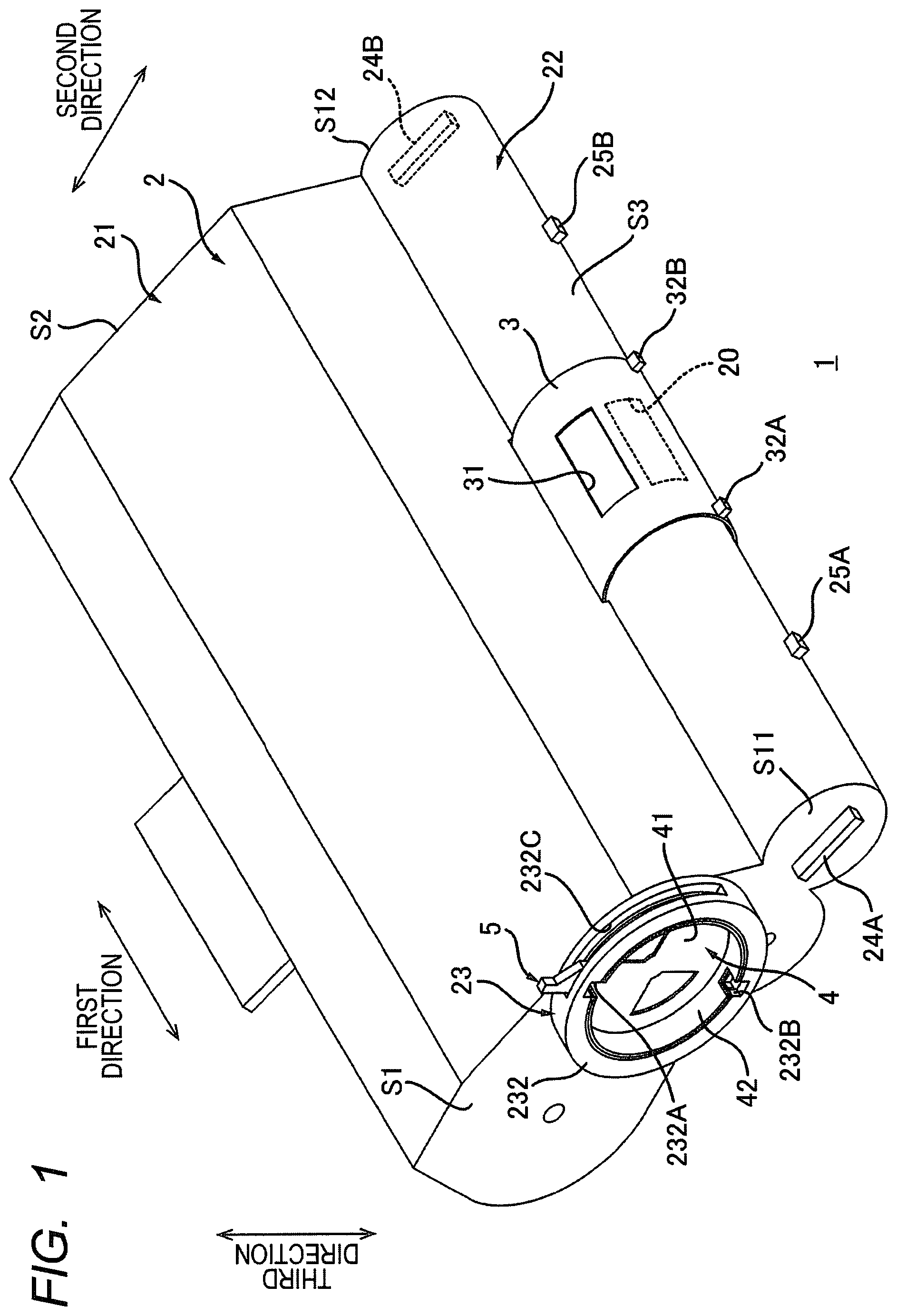
As shown in , the toner cartridge 1 includes a toner housing 2 , a discharge shutter 3 , a reception shutter 4 (see ), and a lever 5 . As shown in , the toner cartridge 1 further includes a plurality of agitators 6 A, 6 B, and 6 C.
1.1 Toner Housing 2
As shown in , the toner housing 2 extends in a first direction. The toner housing 2 has a cylindrical shape. The toner housing 2 stores toner. The toner housing 2 has a discharge port 20 .
The discharge port 20 is located at one end of the toner housing 2 in a second direction. The second direction crosses the first direction. For example, the second direction is perpendicular to the first direction. The discharge port 20 is located between one end of the toner housing 2 and the other end of the toner housing 2 in the first direction. The discharge port 20 is located at a center portion of the toner housing 2 in the first direction. The discharge port 20 discharges the toner inside the toner housing 2 .
Specifically, as shown in , the toner housing 2 includes a first storage portion 21 , a second storage portion 22 , a reception portion 23 , two ribs 24 A and 24 B, and two protrusions 25 A and 25 B.
1.1.1 First Storage Portion 21
The first storage portion 21 is located away from the discharge port 20 in the second direction. The first storage portion 21 extends in the first direction. The first storage portion 21 has a cylindrical shape. The first storage portion 21 has an end surface S 1 at one end and an end surface S 2 at the other end in the first direction. The end surface S 1 extends in a direction crossing the first direction. For example, the end surface S 1 extends in a direction perpendicular to the first direction. The end surface S 2 extends in a direction crossing the first direction. For example, the end surface S 2 extends in a direction perpendicular to the first direction. As shown in , the first storage portion 21 has a first storage chamber 21 A. In other words, the toner housing 2 has the first storage chamber 21 A.
The first storage chamber 21 A is an internal space of the first storage portion 21 . The first storage portion 21 stores toner in the first storage chamber 21 A. The first storage chamber 21 A is located away from the discharge port 20 in the second direction. The volume of the first storage chamber 21 A is larger than the volume of a second storage chamber 22 A of the second storage portion 22 . The second storage chamber 22 A will be described later.
1.1.2 Second Storage Portion 22
As shown in , the second storage portion 22 is located at one end of the toner housing 2 in the second direction. The second storage portion 22 is connected to one end of the first storage portion 21 in the second direction. The second storage portion 22 extends in the first direction. The second storage portion 22 has a cylindrical shape. A circumferential surface S 3 of the second storage portion 22 crosses the end surface S 1 of the toner housing 2 in the first direction. For example, the circumferential surface S 3 of the second storage portion 22 is perpendicular to the end surface S 1 of the toner housing 2 in the first direction. As shown in , the second storage portion 22 has the second storage chamber 22 A and the discharge port 20 described above. In other words, the toner housing 2 has the second storage chamber 22 A.
The second storage chamber 22 A is an internal space of the second storage portion 22 . The second storage portion 22 stores toner in the second storage chamber 22 A. The second storage chamber 22 A is located between the first storage chamber 21 A and the discharge port 20 in the second direction. The second storage chamber 22 A communicates with the first storage chamber 21 A. The volume of the second storage chamber 22 A is smaller than the volume of the first storage chamber 21 A of the first storage portion 21 .
As shown in , the discharge port 20 is located at a center portion of the second storage portion 22 in the first direction. The discharge port 20 is located on the circumferential surface S 3 of the second storage portion 22 . That is, the discharge port 20 is located on the surface that crosses the end surface S 1 of the toner housing 2 in the first direction. The discharge port 20 communicates with the second storage chamber 22 A.
1.1.3 Reception Portion 23
The reception portion 23 is located at one end of the toner housing 2 in the first direction. The reception portion 23 is located at the end surface S 1 of the toner housing 2 at one end in the first direction. Specifically, the reception portion 23 is located on the end surface S 1 of the first storage portion 21 at one end in the first direction. The reception portion 23 is connectable to a toner container 10 (see ). The toner container 10 will be described later. The reception portion 23 has a circular shape. As shown in , the reception portion 23 has a plurality of reception ports 231 A and 231 B and a frame 232 .
1.1.3.1 Reception Ports 231 A and 231 B
The reception port 231 A is located on the end surface S 1 of the first storage portion 21 at one end in the first direction. The reception port 231 A communicates with the first storage chamber 21 A (see ). The reception port 231 A receives toner into the toner housing 2 .
The reception port 231 B is located at the end surface S 1 of the first storage portion 21 at one end in the first direction. The reception port 231 B is located away from the reception port 231 A in the radial direction of the reception portion 23 . The reception port 231 B is located on the opposite side of the reception port 231 A with respect to a center C of the reception portion 23 in the radial direction of the reception portion 23 . The reception port 231 B communicates with the first storage chamber 21 A (see ). The reception port 231 B receives toner into the toner housing 2 together with the reception port 231 A.
1.1.3.2 Frame 232
As shown in , the frame 232 supports the reception shutter 4 and the lever 5 . The frame 232 protrudes from the end surface S 1 of the first storage portion 21 at one end in the first direction. The frame 232 extends in the first direction. The frame 232 has a cylindrical shape. The frame 232 surrounds the reception ports 231 A and 231 B (see ). The frame 232 has a plurality of grooves 232 A, 232 B and a through hole 232 C.
The groove 232 A is located at one end of the frame 232 in a third direction. The third direction crosses the first direction and the second direction. For example, the third direction is perpendicular to the first direction and the second direction. The groove 232 A is located on the inner circumferential edge of the frame 232 . The groove 232 A is recessed outward from the inner circumferential edge of the frame 232 in the third direction.
The groove 232 B is located at the other end of the frame 232 in the third direction. The groove 232 B is located on the opposite side of the groove 232 A with respect to the center C of the reception portion 23 (see ) in the third direction. The groove 232 B is located at the inner circumferential edge of the frame 232 . The groove 232 B is recessed outward from the inner circumferential edge of the frame 232 in the third direction.
The through hole 232 C is located on the circumferential surface of the frame 232 . The through hole 232 C extends in the circumferential direction of the frame 232 .
1.1.4 Ribs 24 A and 24 B
As shown in , the rib 24 A is located on an end surface S 11 of the second storage portion 22 at one end in the first direction. The rib 24 A protrudes from the end surface S 11 of the second storage portion 22 at one end in the first direction. As shown in , the rib 24 A extends in a fourth direction.
As shown in , the rib 24 B is located on an end surface S 12 of the second storage portion 22 at the other end in the first direction. The rib 24 B protrudes from the end surface S 12 of the second storage portion 22 at the other end in the first direction. The rib 24 B extends in the same direction as the rib 24 A.
1.1.5 Protrusions 25 A and 25 B
As shown in , the protrusion 25 A is located between the discharge shutter 3 and the rib 24 A in the first direction. The protrusion 25 A is located on the circumferential surface S 3 of the second storage portion 22 . As shown in , the protrusion 25 A is located on the opposite side of the first storage portion 21 with respect to the second storage portion 22 in the fourth direction. The protrusion 25 A protrudes from the circumferential surface S 3 of the second storage portion 22 . The protrusion 25 A extends in the same direction as the rib 24 A.
As shown in , the protrusion 25 B is located between the discharge shutter 3 and the rib 24 B in the first direction. The protrusion 25 B is located on the circumferential surface S 3 of the second storage portion 22 . The protrusion 25 B is located on the opposite side of the first storage portion 21 with respect to the second storage portion 22 in the fourth direction (see ). The protrusion 25 B protrudes from the circumferential surface S 3 of the second storage portion 22 . The protrusion 25 B extends in the same direction as the rib 24 A.
1.2 Discharge shutter 3
The discharge shutter 3 opens and closes the discharge port 20 . The discharge shutter 3 is located on the circumferential surface S 3 of the second storage portion 22 . The discharge shutter 3 is located at a center portion of the second storage portion 22 in the first direction. The discharge shutter 3 extends in the first direction and in the circumferential direction of the second storage portion 22 . The discharge shutter 3 has a cylindrical shape.
As shown in , the discharge shutter 3 is movable between a discharge shutter closed position (see ) and a discharge shutter open position (see ) in the circumferential direction of the second storage portion 22 . As shown in , the discharge shutter 3 closes the discharge port 20 in a state where the discharge shutter 3 is located at the discharge shutter closed position. As shown in , the discharge port 20 is opened in a state where the discharge shutter 3 is located at the discharge shutter open position.
Specifically, as shown in , the discharge shutter 3 has an opening 31 and two protrusions 32 A and 32 B.
The opening 31 is located at a center portion of the discharge shutter 3 in the first direction. The opening 31 is located between the protrusion 32 A and the protrusion 32 B in the first direction. As shown in , in a state where the discharge shutter 3 is located at the discharge shutter closed position, the opening 31 is located away from the discharge port 20 . As shown in , in a state where the discharge shutter 3 is located at the discharge shutter open position, at least part of the opening 31 communicates with the discharge port 20 .
As shown in , the protrusion 32 A is located at one end of the discharge shutter 3 in the first direction. The protrusion 32 A is located on one side of the opening 31 in the first direction. The protrusion 32 A extends from the outer circumferential surface of the discharge shutter 3 . The protrusion 32 A extends in a direction crossing the first direction. For example, the protrusion 32 A extends in a direction perpendicular to the first direction. Specifically, the protrusion 32 A extends in a radial direction of the discharge shutter 3 . The protrusion 32 A has a prismatic shape.
The protrusion 32 B is located at the other end of the discharge shutter 3 in the first direction. The protrusion 32 B is located on the other side of the opening 31 in the first direction. The protrusion 32 B is located on the opposite side of the protrusion 32 A with respect to the opening 31 in the first direction. The protrusion 32 B extends from the outer circumferential surface of the discharge shutter 3 . The protrusion 32 B extends in a direction crossing the first direction. For example, the protrusion 32 B extends in a direction perpendicular to the first direction. Specifically, the protrusion 32 B extends in the radial direction of the discharge shutter 3 . The protrusion 32 B has a prismatic shape.
1.3 Reception Shutter 4
The reception shutter 4 opens and closes reception ports 231 A and 231 B (see ). The reception shutter 4 is attached to the reception portion 23 . The reception shutter 4 is located inside the frame 232 in the radial direction of the reception portion 23 .
As shown in , the reception shutter 4 is movable between a reception shutter closed position (see ) and a reception shutter open position (see ). As shown in , the reception shutter 4 closes the reception ports 231 A and 231 B in a state where the reception shutter 4 is located at the reception shutter closed position. As shown in , the reception shutter 4 opens the reception ports 231 A and 231 B in a state where the reception shutter 4 is located at the reception shutter open position. The reception shutter 4 is rotatable about an axis A 1 between the reception shutter closed position and the reception shutter open position. The axis A 1 extends in the first direction. For example, the axis A 1 is the same as the center C of the reception portion 23 .
Specifically, as shown in , the reception shutter 4 includes a shutter main body 41 and a rib 42 .
The shutter main body 41 has a disk shape. The shutter main body 41 has a plurality of openings 411 A and 411 B.
As shown in , in a state where the reception shutter 4 is located at the reception shutter closed position, the opening 411 A is located away from the reception port 231 A. As shown in , in a state where the reception shutter 4 is located at the reception shutter open position, at least part of the opening 411 A communicates with the reception port 231 A.
As shown in , the opening 411 B is located away from the opening 411 A in the radial direction of the shutter main body 41 . The opening 411 B is located on the opposite side of the opening 411 A with respect to the axis A 1 in the radial direction of the shutter main body 41 . In a state where the reception shutter 4 is located at the reception shutter closed position, the opening 411 B is located away from the reception port 231 B. As shown in , in a state where the reception shutter 4 is located at the reception shutter open position, at least part of the opening 411 B communicates with the reception port 231 B.
As shown in , the rib 42 is located on the edge of the shutter main body 41 . The rib 42 protrudes from the shutter main body 41 in the first direction. The rib 42 extends in the circumferential direction of the shutter main body 41 . The rib 42 has a plurality of grooves 421 A and 421 B.
The groove 421 A is recessed from one end edge of the rib 42 in the first direction toward the shutter main body 41 . In a state where the reception shutter 4 is located at the reception shutter closed position, the groove 421 A communicates with the groove 232 A of the frame 232 (see ).
The groove 421 B is located on the opposite side of the groove 421 A with respect to the axis A 1 in the radial direction of the shutter main body 41 . The groove 421 B is recessed from one end edge of the rib 42 in the first direction toward the shutter main body 41 . In a state where the reception shutter 4 is located at the reception shutter closed position, the groove 421 B communicates with the groove 232 B of the frame 232 (see ).
1.4 Lever 5
As shown in , the lever 5 is movable between a first position (see ) and a second position (see ). The lever 5 is rotatable about an axis A 2 between the first position and the second position. The axis A 2 extends in the first direction. For example, the axis A 2 is the same as the center C of the reception portion 23 .
As shown in , in a state where the toner container 10 is detached from the toner cartridge 1 , the lever 5 is rotatable relative to the reception shutter 4 . Thus, even if the lever 5 moves from the first position to the second position in a state where the reception shutter 4 is located at the reception shutter closed position and the toner container 10 is detached from the toner cartridge 1 , the reception shutter 4 does not move from the reception shutter closed position.
As shown in , the lever 5 includes an engaging portion 51 and a protruding portion 52 .
In a state where the toner container 10 (see ) is connected to the reception portion 23 , the engaging portion 51 , together with the reception shutter 4 , engages with a container shutter 12 (see ) of the toner container 10 . The container shutter 12 will be described later. The engaging portion 51 has a ring shape. The engaging portion 51 is located inside the frame 232 in the radial direction of the reception portion 23 . The engaging portion 51 is located outside the reception shutter 4 in the radial direction of the reception portion 23 . The engaging portion 51 has a plurality of grooves 511 A and 511 B.
The groove 511 A is recessed from one end edge of the engaging portion 51 toward the other side in the first direction. In a state where the reception shutter 4 is located at the reception shutter closed position and the lever 5 is located at the first position, the groove 511 A communicates with the groove 421 A of the reception shutter 4 and the groove 232 A of the frame 232 (see ).
The groove 511 B is located on the opposite side of the groove 511 A with respect to the axis A 2 in the radial direction of the engaging portion 51 . The groove 511 B is recessed from one end edge of the engaging portion 51 toward the other side in the first direction. In a state where the reception shutter 4 is located at the reception shutter closed position and the lever 5 is located at the first position, the groove 511 B communicates with the groove 421 B of the reception shutter 4 and the groove 232 B of the frame 232 (see ).
The protruding portion 52 is located outside the engaging portion 51 in the radial direction of the engaging portion 51 . The protruding portion 52 extends in the radial direction of the engaging portion 51 . The protruding portion 52 extends from the engaging portion 51 . The protruding portion 52 protrudes outside the frame 232 through the through hole 232 C of the frame 232 .
1.5 Agitators 6 A, 6 B, and 6 C
As shown in , the agitator 6 A is located inside the first storage chamber 21 A. The agitator 6 A is located away from the second storage chamber 22 A in the second direction. The agitator 6 A conveys the toner in the first storage chamber 21 A toward the second storage chamber 22 A. The agitator 6 A is rotatable about an agitator axis A 11 . The agitator axis A 11 extends in the first direction. The agitator axis A 11 is located on one side of the second storage portion 22 in the third direction.
The agitator 6 B is located inside the first storage chamber 21 A. The agitator 6 B is located between the agitator 6 A and the second storage chamber 22 A in the second direction. The agitator 6 B conveys, together with the agitator 6 A, the toner in the first storage chamber 21 A toward the second storage chamber 22 A. The agitator 6 B is rotatable about an agitator axis A 12 . The agitator axis A 12 extends in the first direction. The agitator axis A 12 is located on the other side of the agitator axis A 11 in the third direction.
The agitator 6 C is located in the second storage chamber 22 A. The agitator 6 C conveys the toner in the second storage chamber 22 A toward the discharge port 20 . The agitator 6 C is rotatable about an agitator axis A 13 . The agitator axis A 13 extends in the first direction. The agitator axis A 13 is aligned with the agitator axis A 12 in the second direction. The second direction is the direction connecting the agitator axis A 12 and the agitator axis A 13 .
2. Toner Container 10
Next, details of the toner container 10 will be described with reference to to 15 .
The toner container 10 shown in is configured to contain toner. The toner in the toner container 10 is supplied to the toner housing 2 (see ) of the toner cartridge 1 described above.
Specifically, as shown in , in order to supply toner to the toner cartridge 1 , in a state where the toner cartridge 1 is detached from the image forming apparatus and the reception shutter 4 (see ) is located at the reception shutter closed position, the user connects the toner container 10 containing toner to the reception portion 23 of the toner cartridge 1 (connecting step).
Next, as shown in , in a state where the toner container 10 is connected to the reception portion 23 , the user moves the lever 5 from the first position to the second position, thereby moving the reception shutter 4 from the reception shutter closed position to the reception shutter open position (shutter opening step). In a state where the toner container 10 is connected to the reception portion 23 and the reception shutter 4 is located at the reception shutter open position, the reception ports 231 A and 231 B (see ) is configured to receive toner from the toner container 10 . In a state where the toner container 10 is connected to the reception portion 23 and the reception shutter 4 is located at the reception shutter open position, the toner container 10 is undetachable from the toner cartridge 1 .
Next, as shown in , in a state where the toner container 10 is connected to the reception portion 23 and the reception shutter 4 is located at the reception shutter open position, the user causes the toner container 10 to be located above the toner cartridge 1 and supplies the toner in the toner container 10 into the toner housing 2 .
At this time, since the toner container 10 is undetachable from the toner cartridge 1 , the user shakes the toner cartridge 1 in a state where the toner container 10 is connected to the reception portion 23 . Thus, the toner in the toner container 10 is smoothly supplied into the toner housing 2 .
Next, as shown in , in a state where the toner container 10 is connected to the reception portion 23 , the user moves the lever 5 from the second position to the first position, thereby moving the reception shutter 4 from the reception shutter open position to the reception shutter closed position (shutter closing step). In a state where the toner container 10 is connected to the reception portion 23 and the reception shutter 4 is located at the reception shutter closed position, the toner container 10 is detachable from the toner cartridge 1 .
After that, the user detaches the toner container 10 from the toner cartridge 1 . This completes supply of toner.
Specifically, as shown in , the toner container 10 includes a container main body 11 , the container shutter 12 , and a seal member 13 .
In the following description, the “first direction” of the toner container 10 is the “first direction” in a state where the toner container 10 is connected to the reception portion 23 of the toner cartridge 1 .
2.1 Container Main Body 11
As shown in , the container main body 11 is configured to contain toner. In this embodiment, the container main body 11 includes a pouch 111 and a connection member 112 .
The pouch 111 is made of a soft resin, for example. The pouch 111 is configured to contain toner therein. The pouch 111 extends in the first direction. The pouch 111 has one end 111 A and an other end 111 B in the first direction. The one end 111 A has an opening (not shown). The other end 111 B is located away from the one end 111 A in the first direction.
The connection member 112 is connected to the one end 111 A of the pouch 111 .
The connection member 112 closes an opening (not shown) of the pouch 111 . As shown in , in a state where the toner container 10 is connected to the reception portion 23 of the toner cartridge 1 , the connection member 112 is connected to the reception portion 23 . The connection member 112 is made of hard resin, for example. As shown in , the connection member 112 includes a base 1121 and a protruding portion 1122 .
The base 1121 is connected to the one end 111 A of the pouch 111 . The base 1121 extends in the first direction. The base 1121 has a cylindrical shape. The base 1121 has a plurality of discharge ports 110 A and 110 B. That is, the container main body 11 has the discharge ports 110 A and 110 B.
The discharge port 110 A is located at the end surface of the base 1121 in the first direction. The discharge port 110 A communicates with the inner space of the pouch 111 . The discharge port 110 A discharges the toner inside the container main body 11 .
The discharge port 110 B is located at the end surface of the base 1121 in the first direction. The discharge port 110 B is located away from the discharge port 110 A in the radial direction of the base 1121 . The discharge port 110 B is located on the opposite side of the discharge port 110 A with respect to a center C 2 of the base 1121 in the radial direction of the base 1121 . The discharge port 110 B communicates with the inner space of the pouch 111 . The discharge port 110 B discharges the toner in the container main body 11 together with the discharge port 110 A.
The protruding portion 1122 extends from the end surface of the base 1121 in the first direction. The protruding portion 1122 extends in the first direction. The protruding portion 1122 has a cylindrical shape. The protruding portion 1122 supports the container shutter 12 . The protruding portion 1122 surrounds the discharge ports 110 A and 110 B. The protruding portion 1122 has a plurality of through holes 1122 A and 1122 B.
The through hole 1122 A is located on the circumferential surface of the protruding portion 1122 . The through hole 1122 A extends in the circumferential direction of the protruding portion 1122 .
The through hole 1122 B is located on the circumferential surface of protruding portion 1122 . The through hole 1122 B is located away from the through hole 1122 A in the circumferential direction of the protruding portion 1122 . The through hole 1122 B is located on the opposite side of the through hole 1122 A with respect to the center C 2 of the base 1121 in the radial direction of the base 1121 . The through hole 1122 B extends in the circumferential direction of the protruding portion 1122 .
2.2 Container Shutter 12
As shown in , the container shutter 12 is attached to the protruding portion 1122 . The container shutter 12 is located inside the protruding portion 1122 in the radial direction of the protruding portion 1122 . The container shutter 12 opens and closes the discharge ports 110 A and 110 B of the container main body 11 .
As shown in , 14 and 15 , the container shutter 12 is movable between a container shutter closed position (see ) and a container shutter open position (see ). As shown in , in a state where the container shutter 12 is located at the container shutter closed position, the container shutter 12 closes the discharge ports 110 A and 110 B (see ). As shown in , in a state where the container shutter 12 is located at the container shutter open position, the container shutter 12 opens the discharge ports 110 A and 110 B. The container shutter 12 is rotatable about an axis A 21 between the container shutter closed position and the container shutter open position. The axis A 21 extends in the first direction. For example, the axis A 21 is the same as the center C 2 of base 1121 (see ).
Specifically, as shown in , the container shutter 12 includes a shutter main body 121 and a plurality of protrusions 122 A and 122 B.
The shutter main body 121 has a cylindrical shape. The shutter main body 121 has
a plurality of openings 120 A and 120 B.
As shown in , in a state where the container shutter 12 is located at the container shutter closed position, the opening 120 A is located away from the discharge port 110 A. In a state where the container shutter 12 is located at the container shutter open position (see ), at least part of the opening 120 A communicates with the discharge port 110 A.
As shown in , the opening 120 B is located away from the opening 120 A in the radial direction of the shutter main body 121 . As shown in , the opening 120 B is located on the opposite side of the opening 120 A with respect to the axis A 21 in the radial direction of the shutter main body 121 . In a state where the container shutter 12 is located at the container shutter closed position, the opening 120 B is located away from the discharge port 110 B. In a state where the container shutter 12 is located at the container shutter open position (see ), at least part of the opening 120 B communicates with the discharge port 110 B.
As shown in , the protrusion 122 A is located on the circumferential surface of the shutter main body 121 . The protrusion 122 A protrudes from the circumferential surface of the shutter main body 121 . The protrusion 122 A extends in a radial direction of the shutter main body 121 . As shown in , the protrusion 122 A protrudes outside the protruding portion 1122 through the through hole 1122 A of the protruding portion 1122 .
The protrusion 122 B is located on the opposite side of the protrusion 122 A with respect to the axis A 21 (see ) in the radial direction of the shutter main body 121 . The protrusion 122 B is located on the circumferential surface of the shutter main body 121 . The protrusion 122 B protrudes from the circumferential surface of the shutter main body 121 . The protrusion 122 B extends in a radial direction of the shutter main body 121 . The protrusion 122 B protrudes outside the protruding portion 1122 through the through hole 1122 B (see ) of the protruding portion 1122 .
As shown in , when the toner container 10 is connected to the reception portion 23 of the toner cartridge 1 in a state where the reception shutter 4 of the toner cartridge 1 is located at the reception shutter closed position, the lever 5 of the toner cartridge 1 is located at the first position, and the container shutter 12 of the toner container 10 is located at the container shutter closed position, the protrusion 122 A fits into the groove 421 A of the reception shutter 4 and the groove 511 A of the lever 5 through the groove 232 A (see ) of the frame 232 . Further, the protrusion 122 B fits into the groove 421 B of the reception shutter 4 and the groove 511 B of the lever 5 through the groove 232 B (see ) of the frame 232 . In a state where the protrusion 122 A fits in the groove 421 A and the groove 511 A and the protrusion 122 B fits in the groove 421 B and the groove 511 B, the container shutter 12 is movable together with the reception shutter 4 and the lever 5 .
Thus, as shown in , when the user moves the lever 5 from the first position (see ) to the second position (see ) in the shutter opening step, the container shutter 12 moves from the container shutter closed position (see ) to the container shutter open position (see ), and the reception shutter 4 moves from the reception shutter closed position (see ) to the reception shutter open position (see )
That is, as shown in , in a state where the toner container 10 is connected to the reception portion 23 and the lever 5 is located at the second position, the lever 5 causes the container shutter 12 to be located at the container shutter open position and causes the reception shutter 4 to be located at the reception shutter open position. Thus, in a state where the toner container 10 is connected to the reception portion 23 and the reception shutter 4 is located at the reception shutter open position, the container shutter 12 opens the discharge ports 110 A and 110 B (see ) of the container main body 11 .
In a state where the toner container 10 is connected to the reception portion 23 and the container shutter 12 is located at the container shutter open position, the protrusions 122 A and 122 B of the container shutter 12 engages with the inner circumferential edge of the frame 232 (see ). Thus, as described above and shown in , in a state where the toner container 10 is connected to the reception portion 23 and the reception shutter 4 is located at the reception shutter open position, the toner container 10 is undetachable from the toner cartridge 1 .
In the shutter closing step described above, when the user moves the lever 5 from the second position (see ) to the first position (see ), the container shutter 12 moves from the container shutter open position to the container shutter closed position, and the reception shutter 4 moves from the reception shutter open position to the reception shutter closed position.
That is, as shown in , in a state where the toner container 10 is connected to the reception portion 23 and the lever 5 is located at the first position, the lever 5 causes the container shutter 12 to be located at the container shutter closed position and causes the reception shutter 4 to be located at the reception shutter closed position. In a state where the toner container 10 is connected to the reception portion 23 and the reception shutter 4 is located at the reception shutter closed position, the container shutter 12 closes the discharge ports 110 A and 110 B (see ) of the container main body 11 .
In a state where the toner container 10 is connected to the reception portion 23 and the container shutter 12 is located at the container shutter closed position, the protrusion 122 A of the container shutter 12 overlaps the groove 232 A of the frame 232 (see ), and the protrusion 122 B of the container shutter 12 overlaps the groove 232 B of the frame 232 (see ). Thus, as described above and shown in , in a state where the toner container 10 is connected to the reception portion 23 and the reception shutter 4 is located at the reception shutter closed position, the toner container 10 is detachable from the toner cartridge 1 .
2.3 Seal Member 13
As shown in , the seal member 13 seals between the base 1121 of the connection member 112 and the shutter main body 121 of the container shutter 12 . The seal member 13 is located between the base 1121 of the connection member 112 and the shutter main body 121 of the container shutter 12 in the first direction. The seal member 13 is fixed to the base 1121 of the connection member 112 . As shown in , the seal member 13 is located inside the shutter main body 121 in the radial direction of the shutter main body 121 . The seal member 13 has a disc shape. The seal member 13 is made of sponge, for example. The seal member 13 has a plurality of openings 130 A and 130 B. At least part of the opening 130 A communicates with the discharge port 110 A (see ). At least part of the opening 130 B communicates with the discharge port 110 B (see ).
4. Image Forming Apparatus 100
Next, an image forming apparatus 100 to which the toner cartridge 1 is attached will be described with reference to to 23 .
In the following description of the image forming apparatus 100 , “first direction,” “second direction,” and “third direction” mean “first direction”, “second direction” and “third direction” in a state where the toner cartridge 1 is attached to the image forming apparatus 100 .
4.1 Outline of Image Forming Apparatus 100
As shown in , the image forming apparatus 100 includes a main housing 101 , a cover 102 , a sheet storage section 103 , a drum cartridge 104 , the toner cartridge 1 described above, an exposure device 105 , and a fuser (fixing device) 106 .
4.1.1 Main Housing 101
The main housing 101 accommodates the sheet storage section 103 , the drum cartridge 104 , the exposure device 105 , and the fuser 106 . The main housing 101 has an opening 101 A (see ).
4.1.2 Cover 102
The cover 102 is movable between a cover closed position (see ) and a cover open position (see ). As shown in , the cover 102 closes the opening 101 A in a state where the cover 102 is located at the cover closed position. As shown in , the opening 101 A is opened in a state where the cover 102 is located at the cover open position.
4.1.3 Sheet Storage Section 103
As shown in , the sheet storage section 103 is configured to store sheets S therein.
The sheet S in the sheet storage section 103 is conveyed toward a transfer roller 1044 . The transfer roller 1044 will be described later.
4.1.4 Drum Cartridge 104
The drum cartridge 104 is attached to the image forming apparatus 100 . In a state where the drum cartridge 104 is attached to the image forming apparatus 100 , the drum cartridge 104 is located inside the main housing 101 . As shown in , in a state where the cover 102 is located at the cover open position, the drum cartridge 104 is attachable to and detachable from the image forming apparatus 100 through the opening 101 A. The drum cartridge 104 is detached from the image forming apparatus 100 , for example, when replacement of the drum cartridge 104 is required.
As shown in , the drum cartridge 104 includes a photosensitive drum 1041 , a charging roller 1042 , a development unit 1043 , and the transfer roller 1044 .
4.1.4.1 Photosensitive Drum 1041
The photosensitive drum 1041 is rotatable about a drum axis A 101 . The drum axis A 101 extends in the first direction. The photosensitive drum 1041 extends in the first direction. The photosensitive drum 1041 has a cylindrical shape.
4.1.4.2 Charging Roller 1042
The charging roller 1042 charges the photosensitive drum 1041 . The image forming apparatus 100 may include a scorotron charger instead of the charging roller 1042 .
4.1.4.3 Development Unit 1043
The development unit 1043 supplies toner to the photosensitive drum 1041 . The development unit 1043 includes a development housing 1043 A and a development roller 1043 B.
The development housing 1043 A is configured to store toner. The development housing 1043 A supports the development roller 1043 B.
The development roller 1043 B supplies toner in the development housing 1043 A to the photosensitive drum 1041 . The development roller 1043 B contacts the photosensitive drum 1041 . The development roller 1043 B may be separable from the photosensitive drum 1041 . The development roller 1043 B is rotatable about a development axis A 102 . The development axis A 102 extends in the first direction.
4.1.4.4 Transfer Roller 1044
The transfer roller 1044 transfers the toner on the photosensitive drum 1041 onto the sheet S. Specifically, the sheet S from the sheet storage section 103 passes between the transfer roller 1044 and the photosensitive drum 1041 . At this time, the transfer roller 1044 transfers the toner on the photosensitive drum 1041 onto the sheet S. The transfer roller 1044 contacts the photosensitive drum 1041 .
4.1.5 Toner Cartridge 1
The toner cartridge 1 is attachable to and detachable from the drum cartridge 104 . Specifically, the toner cartridge 1 is attachable to and detachable from the development unit 1043 of the drum cartridge 104 . In a state where the toner cartridge 1 is attached to the drum cartridge 104 , the toner cartridge 1 supplies toner to the development housing 1043 A.
In a state where the toner cartridge 1 is attached to the drum cartridge 104 , the drum cartridge 104 is attached to the image forming apparatus 100 , and the image forming apparatus 100 is placed on a horizontal surface, the third direction is the same as the upper-lower direction. In a state where the toner cartridge 1 is attached to the drum cartridge 104 , the drum cartridge 104 is attached to the image forming apparatus 100 , and the image forming apparatus 100 is placed on a horizontal surface, one side in the third direction is the upper side and the other side in the third direction is the lower side. In a state where the toner cartridge 1 is attached to the drum cartridge 104 , the drum cartridge 104 is attached to the image forming apparatus 100 , and the image forming apparatus 100 is placed on a horizontal surface, the first direction and the second direction are horizontal directions.
4.1.6 Exposure Device 105
The exposure device 105 exposes the photosensitive drum 1041 . Specifically, in a state where the drum cartridge 104 is attached to the main housing 101 , the exposure device 105 exposes the surface of the photosensitive drum 1041 charged by the charging roller 1042 . The development unit 1043 supplies toner to the exposed surface of the photosensitive drum 1041 . In this embodiment, the exposure device 105 is a laser scanning unit. The exposure device 105 may be an LED head.
4.1.7 Fuser 106
The fuser 106 fixes the toner transferred on the sheet S onto the sheet S. In this embodiment, the fuser 106 fixes the toner onto the sheet S by heating and pressurizing the sheet S on which the toner has been transferred. The sheet S that has passed through the fuser 106 is discharged onto the upper surface of the main housing 101 .
4.2 Details of Drum Cartridge 104
As shown in , the drum cartridge 104 includes a frame 1040 , a waste toner pipe 1045 , and a conveyance member 1046 , in addition to the above-described photosensitive drum 1041 , the charging roller 1042 (see ), the development unit 1043 , and the transfer roller 1044 (see ).
4.2.1 Frame 1040
The frame 1040 supports the photosensitive drum 1041 , the charging roller 1042 , the development unit 1043 , and the transfer roller 1044 . The frame 1040 includes two drum side plates 1040 A and 1040 B, a waste toner storage portion 1047 , and a drum cleaning member 1048 (see ). In other words, the drum cartridge 104 includes the waste toner storage portion 1047 and the drum cleaning member 1048 .
4.2.1.1 Drum Side Plates 1040 A and 1040 B
As shown in , the drum side plate 1040 A is located at one end of the frame 1040 in the first direction. The drum side plate 1040 A supports one end of the photosensitive drum 1041 and one end of the development unit 1043 . The drum side plate 1040 A extends in the second direction and the third direction.
The drum side plate 1040 A has two through holes 10401 A and 10402 A.
The through hole 10401 A is located away from the photosensitive drum 1041 in a fifth direction (see ). The fifth direction is the direction connecting the drum axis A 101 and the development axis A 102 . The through hole 10401 A extends in the fifth direction. The through hole 10401 A is an elongated hole. A protrusion 10432 A of the development unit 1043 fits into the through hole 10401 A. The protrusion 10432 A will be described later.
The through hole 10402 A is located away from the through hole 10401 A in the fifth direction. The through hole 10402 A is located between the photosensitive drum 1041 and the through hole 10401 A in the fifth direction. The through hole 10402 A extends in the fifth direction. The through hole 10402 A is an elongated hole. A protrusion 10433 A of the development unit 1043 fits into the through hole 10402 A. The protrusion 10433 A will be described later.
The drum side plate 1040 B is located at the other end of the frame 1040 in the first direction. The drum side plate 1040 B is located away from the drum side plate 1040 A in the first direction. The drum side plate 1040 B extends in the second direction and the third direction. The drum side plate 1040 B supports the other end of the photosensitive drum 1041 and the other end of the development unit 1043 . The drum side plate 1040 B has two through holes 10401 B and 10402 B.
As shown in , the through hole 10401 B is located away from the photosensitive drum 1041 in the fifth direction. The through hole 10401 B extends in the fifth direction. The through hole 10401 B is an elongated hole. A protrusion 10432 B of the development unit 1043 fits into the through hole 10401 B. The protrusion 10432 B will be described later.
The through hole 10402 B is located away from the through hole 10401 B in the fifth direction. The through hole 10402 B is located between the photosensitive drum 1041 and the through hole 10401 B in the fifth direction. The through hole 10402 B extends in the fifth direction. The through hole 10402 B is an elongated hole. A protrusion 10433 B of the development unit 1043 fits into the through hole 10402 B. The protrusion 10433 B will be described later.
4.2.1.2 Waste Toner Storage Portion 1047
As shown in , the waste toner storage portion 1047 is located between the drum side plate 1040 A and the drum side plate 1040 B in the first direction. The waste toner storage portion 1047 extends in the first direction. One end of the waste toner storage portion 1047 in the first direction is connected to the drum side plate 1040 A. The other end of the waste toner storage portion 1047 in the first direction is connected to the drum side plate 1040 B. As shown in , the waste toner storage portion 1047 has an opening 1047 A. The waste toner storage portion 1047 stores waste toner.
4.2.1.3 Drum Cleaning Member 1048
The drum cleaning member 1048 is attached to the waste toner storage portion 1047 . The drum cleaning member 1048 extends in the first direction. The drum cleaning member 1048 has a plate shape. The drum cleaning member 1048 cleans the circumferential surface of the photosensitive drum 1041 . Specifically, an edge of the drum cleaning member 1048 contacts the surface of the photosensitive drum 1041 . As the photosensitive drum 1041 rotates, waste toner on the surface of the photosensitive drum 1041 contacts the edge of the drum cleaning member 1048 and is removed from the surface of the photosensitive drum 1041 . The removed waste toner is stored in the waste toner storage portion 1047 through the opening 1047 A.
4.2.2 Details of Development Unit 1043
As shown in , the development unit 1043 is located between the drum side plate 1040 A and the drum side plate 1040 B in the first direction. Specifically, the development housing 1043 A is located between the drum side plate 1040 A and the drum side plate 1040 B in the first direction. The development unit 1043 includes two development side plates 10431 A and 10431 B, two protrusions 10432 A and 10433 A, two protrusions 10432 B and 10433 B, a development shutter 10434 , a first screw 10435 (see ), and a second screw 10436 (see ), in addition to the development housing 1043 A and the development roller 1043 B described above.
4.2.2.1 Development Side Plates 10431 A and 10431 B
The development side plate 10431 A is located at one end of the development unit 1043 in the first direction. The development side plate 10431 A supports one end of the development roller 1043 B. The development side plate 10431 A extends in the second direction and the third direction. The development side plate 10431 A has a groove 10437 A. As shown in , when the toner cartridge 1 is attached to the drum cartridge 104 , the groove 10437 A (see ) receives the rib 24 A (see ) of the toner cartridge 1 .
As shown in , the development side plate 10431 B is located at the other end of the development unit 1043 in the first direction. The development side plate 10431 B is located away from the development side plate 10431 A in the first direction. The development side plate 10431 B supports the other end of the development roller 1043 B. The development side plate 10431 B extends in the second direction and the third direction. The development side plate 10431 B has a groove 10437 B. As shown in , when the toner cartridge 1 is attached to the drum cartridge 104 , the groove 10437 B (see ) receives the rib 24 B (see ) of the toner cartridge 1 .
4.2.2.2 Details of Development Housing 1043 A
As shown in , the development housing 1043 A is located between the development side plate 10431 A and the development side plate 10431 B in the first direction. The development housing 1043 A extends in the first direction. One end of the development housing 1043 A in the first direction is connected to the development side plate 10431 A. The other end of the development housing 1043 A in the first direction is connected to the development side plate 10431 B. As shown in , the development housing 1043 A has a partition wall 10438 . The development housing 1043 A has a development reception port 10439 and two recesses 10440 A and 10440 B (see ).
The partition wall 10438 is located inside the development housing 1043 A. The partition wall 10438 partitions the internal space of the development housing 1043 A into a first development chamber 10430 A and a second development chamber 10430 B. The first development chamber 10430 A is located on one side of the second development chamber 10430 B in the third direction. A part of the development roller 1043 B is located inside the second development chamber 10430 B. The development roller 1043 B supplies the toner in the second development chamber 10430 B to the photosensitive drum 1041 . As shown in , the partition wall 10438 extends in the first direction. The partition wall 10438 has two passages 10438 A and 10438 B.
The passage 10438 A is located at one end of the partition wall 10438 in the first direction. The passage 10438 A allows communication between the first development chamber 10430 A and the second development chamber 10430 B.
The passage 10438 B is located at the other end of the partition wall 10438 in the first direction. The passage 10438 B allows communication between the first development chamber 10430 A and the second development chamber 10430 B.
As shown in , the development reception port 10439 is located at a center portion of the development housing 1043 A in the first direction. The development reception port 10439 is located between the recess 10440 A and the recess 10440 B in the first direction. In a state where the toner cartridge 1 is attached to the drum cartridge 104 , the development reception port 10439 receives toner from the toner cartridge 1 . As shown in , the development reception port 10439 overlaps the partition wall 10438 in the second direction.
As shown in , the recess 10440 A is located between the development reception port 10439 and the development side plate 10431 A in the first direction.
The recess 10440 B is located between the development reception port 10439 and the development side plate 10431 B in the first direction. The recess 10440 B is located on the opposite side of the recess 10440 A with respect to the development reception port 10439 in the first direction.
As shown in , when the toner cartridge 1 is attached to the drum cartridge 104 in a state where the discharge shutter 3 of the toner cartridge 1 is located at the discharge shutter closed position (see ), the protrusion 32 A (see ) of the discharge shutter 3 of the toner cartridge 1 fits into the recess 10440 A (see ), and the protrusion 32 B (see ) of the discharge shutter 3 of the toner cartridge 1 fits into the recess 10440 B (see ). Thus, the discharge shutter 3 of the toner cartridge 1 is fixed to the development housing 1043 A.
Then, as shown in , when the toner housing 2 of the toner cartridge 1 is rotated about the second storage portion 22 in a state where the discharge shutter 3 is fixed to the development housing 1043 A, the toner housing 2 rotates relative to the discharge shutter 3 . As a result, the discharge shutter 3 moves from the discharge shutter closed position to the discharge shutter open position relative to the second storage portion 22 of the toner housing 2 .
4.2.2.3 Protrusions 10432 A and 10433 A
As shown in , the protrusion 10432 A is located away from the photosensitive drum 1041 in the fifth direction (see ). The protrusion 10432 A is located at one end of the development unit 1043 in the first direction. The protrusion 10432 A extends in the first direction from the development side plate 10431 A. The protrusion 10432 A has a cylindrical shape. The protrusion 10432 A fits into the through hole 10401 A of the drum side plate 1040 A.
The protrusion 10433 A is located between the photosensitive drum 1041 and the protrusion 10432 A in the fifth direction. The protrusion 10433 A is located at one end of the development unit 1043 in the first direction. The protrusion 10433 A extends in the first direction from the development side plate 10431 A. The protrusion 10433 A has a cylindrical shape. The protrusion 10433 A may be one end of a shaft of the development roller 1043 B. The protrusion 10433 A fits into the through hole 10402 A of the drum side plate 1040 A.
4.2.2.4 Protrusions 10432 B and 10433 B
The protrusion 10432 B is located away from the photosensitive drum 1041 in the fifth direction. The protrusion 10432 B is located at the other end of the development unit 1043 in the first direction. The protrusion 10432 B extends in the first direction from the development side plate 10431 B. The protrusion 10432 B has a cylindrical shape. The protrusion 10432 B fits into the through hole 10401 B of the drum side plate 1040 B.
The protrusion 10433 B is located between the photosensitive drum 1041 and the protrusion 10432 B in the fifth direction. The protrusion 10433 B is located at the other end of the development unit 1043 in the first direction. The protrusion 10433 B extends in the first direction from the development side plate 10431 B. The protrusion 10433 B has a cylindrical shape. The protrusion 10433 B may be the other end of the shaft of the development roller 1043 B. The protrusion 10433 B fits into the through hole 10402 B of the drum side plate 1040 B.
In a state where the protrusion 10432 A fits into the through hole 10401 A of the drum side plate 1040 A, the protrusion 10433 A fits into the through hole 10402 A of the drum side plate 1040 A, the protrusion 10432 B fits into the through hole 10401 B of the drum side plate 1040 B, and the protrusion 10433 B fits into the through hole 10402 B of the drum side plate 1040 B, the development unit 1043 is movable in the fifth direction relative to the photosensitive drum 1041 .
4.2.2.5 Development Shutter 10434
As shown in , the development shutter 10434 is located between the development side plate 10431 A and the development side plate 10431 B in the first direction. The development shutter 10434 extends in the first direction. The development shutter 10434 opens and closes the development reception port 10439 . The development shutter 10434 has two through holes 10434 A, 10434 B and an opening 10434 C.
The through hole 10434 A is located between the recess 10440 A of the development housing 1043 A and the development side plate 10431 A in the first direction.
The through hole 10434 B is located between the recess 10440 B of the development housing 1043 A and the development side plate 10431 B in the first direction.
The opening 10434 C is located at a center portion of the development shutter 10434 in the first direction. The opening 10434 C is located between the through hole 10434 A and the through hole 10434 B in the first direction.
As shown in , when the toner cartridge 1 is attached to the drum cartridge 104 , the protrusion 25 A (see ) of the toner housing 2 of the toner cartridge 1 fits into the through hole 10434 A (see ), and the protrusion 25 B (see ) of the toner housing 2 of the toner cartridge 1 fits into the through hole 10434 B (see ). Thereby, the development shutter 10434 is fixed to the toner housing 2 of the toner cartridge 1 .
Then, as shown in , when the toner housing 2 of the toner cartridge 1 is rotated about the second storage portion 22 in a state where the development shutter 10434 is fixed to the toner housing 2 , the development shutter 10434 moves together with the toner housing 2 from the development shutter closed position (see ) to the development shutter open position (see ).
As shown in , in a state where the development shutter 10434 is located at the development shutter closed position, the development shutter 10434 closes the development reception port 10439 . In a state where the development shutter 10434 is located at the development shutter closed position, the opening 10434 C of the development shutter 10434 is located away from the development reception port 10439 .
As shown in , in a state where the development shutter 10434 is located at the development shutter open position, at least part of the opening 10434 C of the development shutter 10434 overlaps the development reception port 10439 . Thus, in a state where the development shutter 10434 is located at the development shutter open position, the development shutter 10434 opens the development reception port 10439 .
4.2.2.6 First Screw 10435
As shown in , the first screw 10435 is located inside the first development chamber 10430 A of the development housing 1043 A. The first screw 10435 conveys the toner in the first development chamber 10430 A toward the development reception port 10439 in the first direction. The first screw 10435 extends in the first direction. The first screw 10435 is an auger screw.
4.2.2.7 Second Screw 10436
The second screw 10436 is located inside the second development chamber 10430 B of the development housing 1043 A. The second screw 10436 conveys toner in the second development chamber 10430 B toward the passages 10438 A and 10438 B in the first direction. The second screw 10436 extends in the first direction. The second screw 10436 is an auger screw.
4.2.3 Waste Toner Pipe 1045
As shown in , one end of the waste toner pipe 1045 is connected to the waste toner storage portion 1047 . The other end of the waste toner pipe 1045 is connected to a center portion of the development housing 1043 A in the first direction via a seal member 1045 A (see ). As shown in , the seal member 1045 A is located between the other end of the waste toner pipe 1045 and the development housing 1043 A. The seal member 1045 A seals between the other end of the waste toner pipe 1045 and the development housing 1043 A. The other end of the waste toner pipe 1045 communicates with the first development chamber 10430 A. The waste toner in the waste toner storage portion 1047 enters the development housing 1043 A through the waste toner pipe 1045 .
4.2.4 Conveyance Member 1046
As shown in , the conveyance member 1046 is located inside the waste toner storage portion 1047 and the waste toner pipe 1045 . The conveyance member 1046 conveys waste toner in the waste toner storage portion 1047 toward the development housing 1043 A. The conveyance member 1046 is a shaftless screw.
5. Operations and Effects
(1) According to the toner cartridge 1 , as shown in , toner is supplied from the reception portion 23 located on the end surface S 1 in the first direction of the toner housing 2 extending in the first direction.
Thus, as shown in , by supplying toner into the toner housing 2 in a state where one end of the toner housing 2 in the first direction faces upward, the supplied toner is distributed in the first direction by gravity inside the toner housing 2 .
Further, as shown in , by shaking the toner cartridge 1 in a state where the reception shutter 4 is located at the reception shutter closed position, the toner supplied in the toner housing 2 is made uniform in the first direction.
Thus, the toner is smoothly supplied without requiring time for the supplied toner to spread over the entirety of the toner housing 2 .
Further, even if there is no member for conveying the supplied toner in the toner housing 2 in the first direction, the supplied toner is distributed over the entirety of the toner housing 2 .
Further, as shown in , the discharge port 20 is located on the surface S 3 crossing the end surface S 1 .
This suppresses the toner moving toward the discharge port 20 when the toner supplied from the reception portion 23 located at the end surface S 1 flows in the first direction.
As a result, spilling of the supplied toner from the discharge port 20 is suppressed.
(2) According to the toner cartridge 1 , as shown in , the reception portion 23 is connectable to the toner container 10 .
Thus, as shown in , the toner in the toner container 10 is supplied to the toner housing 2 in a state where the toner container 10 is connected to the reception portion 23 of the toner cartridge 1 .
This suppresses spilling of the toner supplied from the toner container 10 to the toner housing 2 .
(3) According to the toner cartridge 1 , as shown in , the toner housing 2 has the first storage chamber 21 A and the second storage chamber 22 A. The first storage chamber 21 A is located away from the discharge port 20 . The reception ports 231 A and 231 B (see ) communicate with the first storage chamber 21 A.
With this configuration, the toner supplied through the reception ports 231 A and 231 B is stored in the first storage chamber 21 A located away from the discharge port 20 .
The second storage chamber 22 A is located between the first storage chamber 21 A and the discharge port 20 . The discharge port 20 communicates with the second storage chamber 22 A.
Thus, the movement of the supplied toner to the discharge port 20 is suppressed by the second storage chamber 22 A.
As a result, spilling of the supplied toner from the discharge port 20 is further suppressed.
(4) According to the toner cartridge 1 , as shown in , in a state where the toner container 10 is connected to the reception portion 23 and the reception shutter 4 is located at the reception shutter open position, the toner container 10 is undetachable from the toner cartridge 1 .
Thus, in a state where the toner container 10 is connected to the reception portion 23 and the reception shutter 4 is located at the reception shutter open position, as shown in , even if the attitude of the toner cartridge 1 is changed and shaken, the toner container 10 does not come off from the toner cartridge 1 .
Thus, in a state where the toner container 10 is connected to the reception portion 23 of the toner cartridge 1 , the attitude of the toner cartridge 1 may be changed, and all the toner in the toner container 10 may be supplied to the toner housing 2 while shaking the toner cartridge 1 .
(5) According to the toner cartridge 1 , as shown in , the toner container 10 includes the container main body 11 and the container shutter 12 .
As shown in , in a state where the toner container 10 is connected to the reception portion 23 and the reception shutter 4 is located at the reception shutter closed position, the container shutter 12 closes the discharge ports 110 A and 110 B of the container main body 11 .
As shown in , in a state where the toner container 10 is connected to the reception portion 23 and the reception shutter 4 is located at the reception shutter open position, the container shutter 12 opens the discharge ports 110 A and 110 B of the container main body 11 .
That is, in a state where the toner container 10 is connected to the reception portion 23 , the container shutter 12 is also opened by an operation of moving the reception shutter 4 from the reception shutter closed position to the reception shutter open position.
Thus, compared to the case where the toner container 10 is connected to the reception portion 23 in a state where the discharge ports 110 A and 110 B of the toner container 10 are open, spilling of the toner in the toner container 10 is suppressed when the toner container 10 is connected to the reception portion 23 .
(6) According to the method of supplying toner, as shown in , first, in a state where the reception shutter 4 is located at the reception shutter closed position, the toner container 10 is connected to the toner cartridge 1 (connecting step). Next, as shown in , in a state where the toner container 10 is connected to the reception portion 23 , the reception shutter 4 is moved from the reception shutter closed position to the reception shutter open position. Next, as shown in , in a state where the toner container 10 is connected to the reception portion 23 and the reception shutter 4 is located at the reception shutter open position, the toner container 10 is located above the toner cartridge 1 and the toner in the toner container 10 is supplied into the toner housing 2 .
With this method, while suppressing spilling of the toner in the toner container 10 , the toner in the toner container 10 is smoothly supplied to the toner cartridge 1 by using gravity.
If the toner container 10 is to be connected to the toner cartridge 1 in a state where one end of the toner housing 2 faces upward in the first direction, there is a possibility that toner spills out when the toner container 10 is connected to the toner cartridge 1 .
In this regard, as shown in , the toner container 10 is placed above the toner cartridge 1 in a state where the toner container 10 is connected to the reception portion 23 and the reception shutter 4 is located at the reception shutter open position.
This suppresses spilling of toner when the toner container 10 and the toner cartridge 1 are connected.
6. Modifications
While the invention has been described in conjunction with various example structures outlined above and illustrated in the figures, various alternatives, modifications, variations, improvements, and/or substantial equivalents, whether known or that may be presently unforeseen, may become apparent to those having at least ordinary skill in the art. Accordingly, the example embodiments of the disclosure, as set forth above, are intended to be illustrative of the invention, and not limiting the invention. Various changes may be made without departing from the spirit and scope of the disclosure. Thus, the disclosure is intended to embrace all known or later developed alternatives, modifications, variations, improvements, and/or substantial equivalents. Some specific examples of potential alternatives, modifications, or variations in the described invention are provided below.
Modifications will be described with reference to to 33 . In the modifications, members similar to those of the embodiment described above are denoted by the same reference numerals, and descriptions thereof are omitted.
(1) As shown in , the cartridge may be a process cartridge 200 . The process cartridge 200 is composed of the toner cartridge 1 and the drum cartridge 104 by attaching the toner cartridge 1 to the drum cartridge 104 . That is, the cartridge further includes the photosensitive drum 1041 . As shown in , the toner container 10 may be connectable to the reception portion 23 of the toner cartridge 1 in a state where the toner cartridge 1 is attached to the drum cartridge 104 . In this case, the drum side plate 1040 A of the drum cartridge 104 may have a concave portion 201 configured to receive the toner container 10 connected to the reception portion 23 of the toner cartridge 1 .
(2) As shown in , the cartridge may be a development cartridge 300 . As shown in , the development cartridge 300 includes a toner housing 301 and a development roller 1043 B. That is, the cartridge includes the development roller 1043 B.
The toner housing 301 has a discharge port 3010 . The discharge port 3010 is located at one end of the toner housing 301 in the second direction. As the development roller 1043 B rotates, the toner in the toner housing 301 is discharged to outside the toner housing 301 through the discharge port 3010 . That is, in a state where the development roller 1043 B is rotating, the toner in the toner housing 301 is discharged through the discharge port 3010 .
Specifically, the toner housing 301 has a first storage portion 3011 , a second storage portion 3012 , and the reception portion 23 (see ).
The first storage portion 3011 is located away from the discharge port 3010 in the second direction. The first storage portion 3011 has a first storage chamber 3011 A. In other words, the toner housing 301 has the first storage chamber 3011 A.
The first storage chamber 3011 A is an internal space of the first storage portion 3011 . The first storage portion 3011 stores toner in the first storage chamber 3011 A. The first storage chamber 3011 A is located away from the discharge port 3010 in the second direction. The volume of the first storage chamber 3011 A is larger than the volume of a second storage chamber 3012 A of the second storage portion 3012 . The second storage chamber 3012 A will be described later.
The second storage portion 3012 is located at one end of the toner housing 301 in the second direction. The second storage portion 3012 is connected to one end of the first storage portion 3011 in the second direction. The second storage portion 3012 has the second storage chamber 3012 A and the discharge port 3010 described above. In other words, the toner housing 301 has the second storage chamber 3012 A.
The second storage chamber 3012 A is an internal space of the second storage portion 3012 . The second storage portion 3012 stores toner in the second storage chamber 3012 A. The second storage chamber 3012 A is located between the first storage chamber 3011 A and the discharge port 3010 in the second direction. The second storage chamber 3012 A communicates with the first storage chamber 3011 A through a passage 3013 . The volume of the second storage chamber 3012 A is smaller than the volume of the first storage chamber 3011 A of the first storage portion 3011 . The discharge port 3010 communicates with the second storage chamber 3012 A.
The development roller 1043 B is supported at one end of the toner housing 301 in the second direction. A part of the development roller 1043 B is located inside the discharge port 3010 .
(3) As shown in , in a state where a toner container 400 is connected to a reception portion 501 , a reception shutter 510 may be rotatable together with the toner container 400 between a reception shutter closed position (see ) and a reception shutter open position (see ).
Specifically, as shown in , the toner container 400 has a cylindrical shape. The toner container 400 extends in the first direction. The toner container 400 includes a container main body 401 and the container shutter 12 .
The container main body 401 stores toner. The container main body 401 includes a bottle 4011 and a connection member 4012 .
The bottle 4011 is made of paper, for example. The bottle 4011 stores toner inside. The bottle 4011 extends in the first direction. The bottle 4011 has one end 4011 A and an other end 4011 B in the first direction. The one end 4011 A has an opening. The other end 4011 B is located away from the one end 4011 A in the first direction. The bottle 4011 has a notch 4011 C. The notch 4011 C is located at the one end 4011 A. The notch 4011 C extends in the first direction.
The connection member 4012 is connected to the one end 4011 A of the bottle 4011 . The connection member 4012 closes the opening of the bottle 4011 . The connection member 4012 extends in the first direction. The connection member 4012 has a cylindrical shape. The connection member 4012 is made of hard resin, for example. The connection member 4012 has a plurality of discharge ports 4010 A, 4010 B, a protrusion 40121 , a plurality of through holes 40122 A, 40122 B, and a plurality of protrusions 40123 A, 40123 B (see ). That is, the container main body 401 has the discharge ports 4010 A and 4010 B.
The discharge ports 4010 A and 4010 B communicate with the inner space of the bottle 4011 . The discharge ports 4010 A and 4010 B discharge the toner inside the container main body 401 . The discharge port 4010 B is located away from the discharge port 4010 A in the radial direction of the connection member 4012 .
The protrusion 40121 fits into the notch 4011 C of the bottle 4011 . Thus, the connection member 4012 rotates about an axis A 401 together with the bottle 4011 . The axis A 401 extends in the first direction.
The through holes 40122 A and 40122 B are located on the circumferential surface of connection member 4012 . The through hole 40122 B is located away from the through hole 40122 A in the circumferential direction of the connection member 4012 . Each of the through holes 40122 A and 40122 B extends in the circumferential direction of connection member 4012 . The protrusion 122 A of the container shutter 12 protrudes outside the connection member 4012 through the through hole 40122 A. The protrusion 122 B of the container shutter 12 protrudes outside the connection member 4012 through the through hole 40122 B.
The protrusion 40123 A is located on the circumferential surface of the connection member 4012 . The protrusion 40123 A extends from the circumferential surface of the connection member 4012 . The protrusion 40123 A extends in a radial direction of the connection member 4012 . In a state where the container shutter 12 is located at the container shutter closed position, the protrusion 40123 A is aligned with the protrusion 122 A of the container shutter 12 in the first direction.
As shown in , the protrusion 40123 B is located on the opposite side of the protrusion 40123 A with respect to the axis A 401 in the radial direction of the connection member 4012 . The protrusion 40123 B is located on the circumferential surface of the connection member 4012 . The protrusion 40123 B extends from the circumferential surface of the connection member 4012 . The protrusion 40123 B extends in the radial direction of the connection member 4012 . In a state where the container shutter 12 is located at the container shutter closed position, the protrusion 40123 B is aligned with the protrusion 122 B (see ) of the container shutter 12 in the first direction.
In this modification, as shown in , the reception portion 501 of the toner cartridge 500 does not have the lever 5 . The reception portion 501 has a plurality of reception ports 231 A and 231 B and a frame 5011 .
As shown in , the frame 5011 supports the reception shutter 510 . The frame 5011 protrudes from the end surface S 1 of the first storage portion 21 at one end in the first direction. The frame 5011 extends in the first direction. The frame 5011 has a cylindrical shape. The frame 5011 surrounds the reception ports 231 A and 231 B (see ). The frame 5011 has a plurality of grooves 5012 A, 5012 B and a plurality of grooves 5013 A, 5013 B (see ).
The groove 5012 A is located at one end of the frame 5011 in the third direction. The groove 5012 A is located at the inner circumferential edge of the frame 5011 . The groove 5012 A is recessed outward from the inner circumferential edge of the frame 5011 in the third direction. The groove 5012 A extends in the first direction (see ).
The groove 5012 B is located at the other end of the frame 5011 in the third direction. The groove 5012 B is located on the opposite side of the groove 5012 A with respect to a center C 3 (see ) of the reception portion 501 in the third direction. The groove 5012 B is located at the inner circumferential edge of the frame 5011 . The groove 5012 B is recessed outward from the inner circumferential edge of the frame 5011 in the third direction. The groove 5012 B extends in the first direction (see ).
As shown in , the groove 5013 A is located on the inner circumferential surface of the frame 5011 . The groove 5013 A extends in the circumferential direction of the frame 5011 from the middle of the groove 5012 A.
As shown in , the groove 5013 B is located away from the groove 5013 A on the inner circumferential surface of the frame 5011 . The groove 5013 B extends in the circumferential direction of the frame 5011 from the middle of the groove 5012 B.
As shown in , the reception shutter 510 has a shutter main body 5101 and a rib 5102 .
The shutter main body 5101 has a disc shape. The shutter main body 5101 has a plurality of openings 5101 A and 5101 B.
In a state where the reception shutter 510 is located at the reception shutter closed position (see ), the opening 5101 A is located away from the reception port 231 A. As shown in , in a state where the reception shutter 510 is located at the reception shutter open position, at least part of the opening 5101 A communicates with the reception port 231 A.
As shown in , the opening 5101 B is located away from the opening 5101 A in the radial direction of the shutter main body 5101 . The opening 5101 B is located on the opposite side of the opening 5101 A with respect to the center C 3 in the radial direction of the shutter main body 5101 . In a state where the reception shutter 510 is located at the reception shutter closed position, the opening 5101 B is located away from the reception port 231 B. As shown in , in a state where the reception shutter 510 is located at the reception shutter open position, at least part of the opening 5101 B communicates with the reception port 231 B.
As shown in , the rib 5102 is located on the edge of the shutter main body 5101 . The rib 5102 protrudes from the shutter main body 5101 in the first direction. The rib 5102 extends in the circumferential direction of the shutter main body 5101 . The rib 5102 has a plurality of grooves 5102 A, 5102 B and a plurality of grooves 5103 A, 5103 B (see ).
As shown in , the groove 5102 A is recessed toward the shutter main body 5101 from one edge of the rib 5102 in the first direction. In a state where the reception shutter 510 is located at the reception shutter closed position, the groove 5102 A communicates with the groove 5012 A of the frame 5011 .
The groove 5102 B is located on the opposite side of the groove 5102 A with respect to the center C 3 in the radial direction of the shutter main body 5101 . The groove 5102 B is recessed toward the shutter main body 5101 from one edge of the rib 5102 in the first direction. In a state where the reception shutter 510 is located at the reception shutter closed position, the groove 5102 B communicates with the groove 5012 B of the frame 5011 .
As shown in , the groove 5103 A extends from the middle of the groove 5102 A in a direction opposite to the rotational direction of the reception shutter 510 from the reception shutter closed position to the reception shutter open position.
As shown in , the groove 5103 B is located away from the groove 5103 A in the direction of rotation of the reception shutter 510 . The groove 5103 B extends from the middle of the groove 5102 B in the direction opposite to the rotation direction of the reception shutter 510 from the reception shutter closed position to the reception shutter open position.
As shown in , in a state where the toner container 400 is connected to the reception portion 501 , the protrusion 122 A of the container shutter 12 fits into the groove 5012 A of the frame 5011 , and the protrusion 122 B of the container shutter 12 fits into the groove 5012 B of the frame 5011 . Thereby, the container shutter 12 is fixed to the frame 5011 of the reception portion 501 .
Further, in a state where toner container 400 is connected to reception portion 501 , the protrusion 40123 A of the toner container 400 fits into the groove 5102 A of the reception shutter 510 , and the protrusion 40123 B of toner container 400 fits into the groove 5102 B of the reception shutter 510 . Thus, the reception shutter 510 rotates together with the container main body 401 .
When the user rotates the container main body 401 about the axis A 401 in a state where the toner container 400 is connected to the reception portion 501 , as shown in , the reception shutter 510 rotates together with the container main body 401 from the reception shutter closed position toward the reception shutter open position in a state where the container shutter 12 is fixed to the frame 5011 of the reception portion 501 .
At this time, the protrusion 122 A of the container shutter 12 is received in the groove 5103 A of the reception shutter 510 (see ), and the protrusion 122 B of the container shutter 12 is received in the groove 5103 B of the reception shutter 510 (see ). Thus, even in a state where the container shutter 12 is fixed to the frame 5011 , the reception shutter 510 is rotated without hitting the protrusions 122 A and 122 B of the container shutter 12 .
At this time, as shown in , the protrusion 40123 A of the toner container 400 is received in the groove 5013 A of the frame 5011 , and the protrusion 40123 B of the toner container 400 is received in the groove 5013 B of the frame 5011 . In this state, the reception ports 231 A, 231 B of the reception portion 501 and the discharge ports 4010 A, 4010 B of the container main body 401 communicate with each other, and toner is supplied from the toner container 400 to the toner housing 2 .
(4) In the modifications (1) to (3), the same effects as those of the above-described embodiment are obtained.
Figures (20)
Citations
This patent cites (22)
- US9360799
- US2008/0170889
- US2008/0317511
- US2009/0097886
- US2016/0313670
- US2017/0219960
- US2019/0094753
- US2022/0155708
- US2023/0017354
- US2024/0241465
- US2024/0241475
- US60-19174
- US7-333964
- US2006-235046
- US2008-241771
- US2009-20302
- US2013137429
- US2015-111211
- US2017-138388
- US2019-61214
- US2021-26202
- US2022-90641