Abstract
A striker mounting structure is configured to mount a striker on a vehicle body. A hook fixed to a door is hooked to the striker. A reinforcement formed with an insertion hole may be attached to the vehicle body. An outer panel covering a reinforcement may include a striker mounting surface spaced from the reinforcement. A reinforcement member may be fixed to the striker and the striker mounting surface. Two or more connecting rods may extend from the reinforcement member. Each of the connecting rods may include locking portions, which are inserted in the insertion hole formed in the reinforcement.
Claims (19)
1. A striker mounting structure, comprising: a reinforcement provided on a vehicle body and formed with one or more insertion hole; an outer panel for covering the reinforcement that has a striker mounting surface arranged to be spaced apart from the reinforcement; a reinforcement member fixed to the striker mounting surface and a striker; and a first connecting rod connected to the reinforcement member, the first connecting rod having a first locking portion extending from the reinforcement member so as to extend into one of the one or more insertion hole formed in the reinforcement; and a second connecting rod connected to the reinforcement member, the second connecting rod having a second locking portion extending from the reinforcement member so as to extend into one of the one or more insertion hole formed in the reinforcement,
15. A striker mounting structure, comprising: a reinforcement provided on a vehicle body and formed with one or more insertion hole; an outer panel for covering the reinforcement that has a striker mounting surface arranged to be spaced apart from the reinforcement; a reinforcement member fixed to the striker mounting surface and a striker; and a first connecting rod connected to the reinforcement member extending toward the one or more insertion hole; and a second connecting rod connected to the reinforcement member extending toward the one of more insertion hole, wherein: the first and second connecting rod are tilted with respect to each other.
19. A striker mounting structure, comprising: a reinforcement provided on a vehicle body and formed with one or more insertion hole; an outer panel for covering the reinforcement that has a striker mounting surface arranged to be spaced apart from the reinforcement; a reinforcement member fixed to the striker mounting surface and a striker; and a first connecting rod connected to the reinforcement member, the first connecting rod having a first locking portion extending from the reinforcement member so as to extend into the one or more insertion hole formed in the reinforcement, wherein: the first locking portion is spaced apart from an opening edge of the one or more insertion hole,
Show 16 dependent claims
2. The striker mounting structure according to claim 1 , wherein: a hook is provided on a rear end of a vehicle door and is configured to hook the striker, and the striker mounting surface is located in front of the reinforcement.
3. The striker mounting structure according to claim 1 , wherein: the one or more insertion hole opens in a direction away from a passenger compartment, each of the first and second connecting rods includes a rod portion extending in a forward/rearward direction of a vehicle, and the first and second locking portions extend from the rod portion in a direction toward the passenger compartment.
4. The striker mounting structure according to claim 1 , wherein the first and second connecting rods are aligned in an upward/downward direction.
5. The striker mounting structure according to claim 1 , wherein an interval between the first and second connecting rods increases or reduces in a direction toward the one or more insertion hole.
6. The striker mounting structure according to claim 1 , further comprising a reinforcement plate extending from the reinforcement member toward the reinforcement.
7. The striker mounting structure according to claim 6 , wherein the connecting rods are fixed to the reinforcement plate.
8. The striker mounting structure according to claim 7 , wherein: the first connecting rod extends along an upper end of the reinforcement plate, the second connecting rod extends along a lower end of the reinforcement plate, and an interval between the first connecting rod and the second connecting rod increases or reduces in a direction toward the reinforcement member.
9. The striker mounting structure according to claim 6 , wherein: the reinforcement plate is a separate component from the reinforcement member, and the reinforcement plate is attached to the reinforcement member.
10. The striker mounting structure according to claim 6 , wherein the reinforcement plate includes a ridge line extending in a forward/backward direction so as to form a convex shape a direction away from a passenger compartment or a direction toward the passenger compartment.
11. The striker mounting structure according to claim 1 , wherein the first and second locking portions extend into the same insertion hole.
12. The striker mounting structure according to claim 1 , wherein the first and second locking portions extend into different insertion holes.
13. The striker mounting structure according to claim 1 , wherein an interval between the first and second locking portions is smaller than a longest length of a striker plate of the striker.
14. The striker mounting structure according to claim 1 , wherein the first and second locking portions are configured to move in opposite directions within the one or more insertion hole during a collision.
16. The striker mounting structure according to claim 15 , wherein the first and second connecting rods extend toward the same insertion hole.
17. The striker mounting structure according to claim 15 , wherein the first and second connecting rods extend in a direction away from the reinforcement so as to be tilted toward each other.
18. The striker mounting structure according to claim 15 , wherein the first and second connecting rods extend in a direction away from the reinforcement so as to be tilted away from each other.
Full Description
Show full text →
CROSS-REFERENCE TO RELATED APPLICATIONS
This application claims priority to Japanese patent application serial number 2019-74494 filed Apr. 10, 2019 the contents of which are incorporated herein by reference in its entirety for all purposes.
BACKGROUND
The present invention relates to a striker mounting structure.
A catcher mounting support structure (corresponding to a striker mounting structure) may be provided for vehicle doors. This mounting structure prevents a door from entering a passenger compartment in the event of a side collision with a vehicle body.
The mounting structure includes a reinforcement and a tubular member (corresponding to a connecting rod) mounted to a vehicle body. The reinforcement has, for example, substantially a box shaped cross section with a reinforcement front and a reinforcement rear. One end of the tubular member is fixed to the reinforcement front and the other end to the reinforcement rear.
The mounting structure is provided on a vehicle body side member, for example, a rear wheel arch part (corresponding to a vehicle body). A catcher (corresponding to a striker) is mounted on the tubular member by screw tightening a mounting bolt(s). This mounting structure is very resistive to input of an impact load in the event of a side collision.
The mounting structure is fixed to the rear wheel arch part. Therefore, the impact load generated in the event of a side collision is directly applied to the reinforcement via the mounting structure. As a result, the reinforcement may be easily deformed due to the impact.
SUMMARY
According to one aspect of the present embodiment, the present disclosure relates to a striker mounting structure that is configured to mount a striker on a vehicle body. A hook fixed on a door is hooked to the striker. A reinforcement formed with an insertion hole(s) may be attached to the vehicle body. An outer panel covering the reinforcement may include a striker mounting surface arranged to be spaced apart from the reinforcement. The reinforcement member may be fixed to the striker and the striker mounting surface. Two or more connecting rods may extend from the reinforcement member. Each of the connecting rods may include locking portions, which are inserted in the insertion hole(s) formed in the reinforcement.
Therefore, when an impact is applied to a lateral side of the vehicle body, the door is deformed and the hook of the door pulls the striker. The reinforcement member and the connecting rods move together with the striker, such that the locking portions of the connecting rods strike a hole wall surface of the insertion hole(s) of the reinforcement. Consequently, the force caused by the collision is not directly, but rather indirectly, applied to the reinforcement. In addition, since more than one connecting rod is provided, the force caused by the collision is applied to the reinforcement at a plurality of spots. As a result, the reinforcement is gradually deformed, such that the door is favorably prevented from entering the passenger compartment. Further, movement of the striker is prevented by more than one connecting rod. Therefore, the striker becoming inclined during the collision may be prevented, which is a problem with only one connecting rod.
According to another aspect of the present embodiment, the hook may be provided at a rear end of the door. The striker mounting surface may be located in front of the reinforcement. Therefore, the impact is reliably transmitted to the reinforcement via the striker mounting surface, when the hook of the door moves forward due to the collision with the door.
According to another aspect of the present embodiment, the insertion hole(s) may open away from the passenger compartment. The connecting rod may include a rod portion extending in a forward/backward direction of a vehicle. The locking portions may extend from the rod portion toward the inside of the passenger compartment, so as to be inserted in the insertion hole(s). Consequently, bent portions are formed between the rod and locking portions. The impact applied to the vehicle body may thus be additionally absorbed due to the deformation of the bent portions.
According to another aspect of the present embodiment, a reinforcement member is abutted to a rear surface of the striker mounting surface, the surface facing the reinforcement. The striker is abutted to a front surface, which is an opposite side of the rear surface of the striker mounting surface. The striker and the reinforcement member thus cooperate to clamp the striker mounting surface. In this way, the striker and the reinforcement member can be securely mounted to the striker mounting surface.
According to another aspect of the present embodiment, two or more connecting rods may be arranged in line in an upward/downward direction. Therefore, the impact force is dispersed in the upward/downward direction. The impact force due applied to the lateral side of the vehicle body is further retained in the reinforcement. As a result, the striker is reliably prevented from being inclined in the upward/downward direction.
According to another aspect of the present embodiment, the first and second connecting rods of the two or more connecting rods may extend from the reinforcement member. The second connecting rod extends such that the interval between the first connecting rod increases or reduces in a direction away from the reinforcement member. Therefore, since the angles of the first connecting rod and the second connecting rod with respect to the reinforcement member are respectively different, the force applied to the reinforcement is dispersed. The impact force is thus effectively retained in the reinforcement. Further, the first connecting rod cooperates with the second connecting rod, so as to effectively prevent the striker from rotating or tilting.
According to another aspect of the present embodiment, a reinforcement plate may be provided so as to extend from the reinforcement member toward the reinforcement. Therefore, the reinforcement member is reinforced by the reinforcement plate, such that the impact force can be effectively retained by the reinforcement member.
According to another aspect of the present embodiment, the connecting rods are fixed to the reinforcement plate. Thus, the reinforcement plate and the connecting rods cooperate to reinforce the reinforcement member. As a result, the impact force can be more effectively retained by the reinforcement member.
According to another aspect of the present embodiment, one of the connecting rods extends along the upper edge of the reinforcement plate and is fixed to the reinforcement plate. The other connecting rod extends along the lower edge of the reinforcement plate and is fixed to the reinforcement plate. These two connecting rods are fixed to the reinforcement plate such that the interval between the two connecting rods increases or reduces in a direction away from the reinforcement member.
The two connecting rods are thus reinforced by the reinforcement plate. Additionally, the impact force applied to the lateral side of the vehicle body is dispersed in the upward/downward direction and retained in the reinforcement. As a result, the striker is reliably prevented from being inclined in the upward/downward direction. Furthermore, since the angles of the first connecting rod and the second connecting rod with respect to the reinforcement member are respectively different, the force applied to the reinforcement is more dispersed. The impact force is thus effectively retained in the reinforcement.
According to another aspect of the present embodiment, the reinforcement plate is a separate component from the reinforcement member and is attached to the reinforcement member. Therefore, the shape of the reinforcement plate can be flexibly selected and may be formed, for example, in a shape corresponding to the shape of the reinforcement.
According to another aspect of the present embodiment, the reinforcement plate may have a ridge line extending in the forward/backward direction, so as to form a convex shape in a direction away from the passenger compartment or toward the passenger compartment. Therefore, the strength of the reinforcement plate in the forward/backward direction may be greater. On the other hand, the reinforcement plate may be easily bent about the ridge lines in the upward/downward direction, so that the impact can be further absorbed by the reinforcement plate.
BRIEF DESCRIPTION OF THE DRAWINGS
is a perspective view of an entire striker mounting structure according to a first embodiment.
is an exploded perspective view of the striker mounting unit of .
is an explanatory view illustrating a detailed structure of the striker mounting structure of .
is an explanatory view illustrating a movement of the striker mounting structure of in the event of a side collision.
is an explanatory view illustrating a movement of the striker mounting structure of in the event of the side collision.
is an explanatory view illustrating a movement of the striker mounting structure of in the event of the side collision.
is an explanatory view of a striker mounting structure according to a second embodiment.
is an explanatory view of a striker mounting structure according to a third embodiment.
is an explanatory view illustrating a movement of a striker mounting structure with one connecting rod.
DETAILED DESCRIPTION
A strike mounting structure will be described with reference to drawings. The striker mounting structure may include, for example, a striker mounting unit configured to mount a striker on a vehicle body. The X-axis, Y-axis, and Z-axis illustrated in the drawings intersect orthogonally with each other. For the purposes of the following discussions, with reference to the vehicle body 1 , an X-direction is set as “forward,” a direction opposite to the X-direction as “backward,” a Z-direction as “upward,” and a direction opposite to the Z-direction as “downward.” The Y-direction is set as “left” and a direction opposite to the Y-direction as “right.”
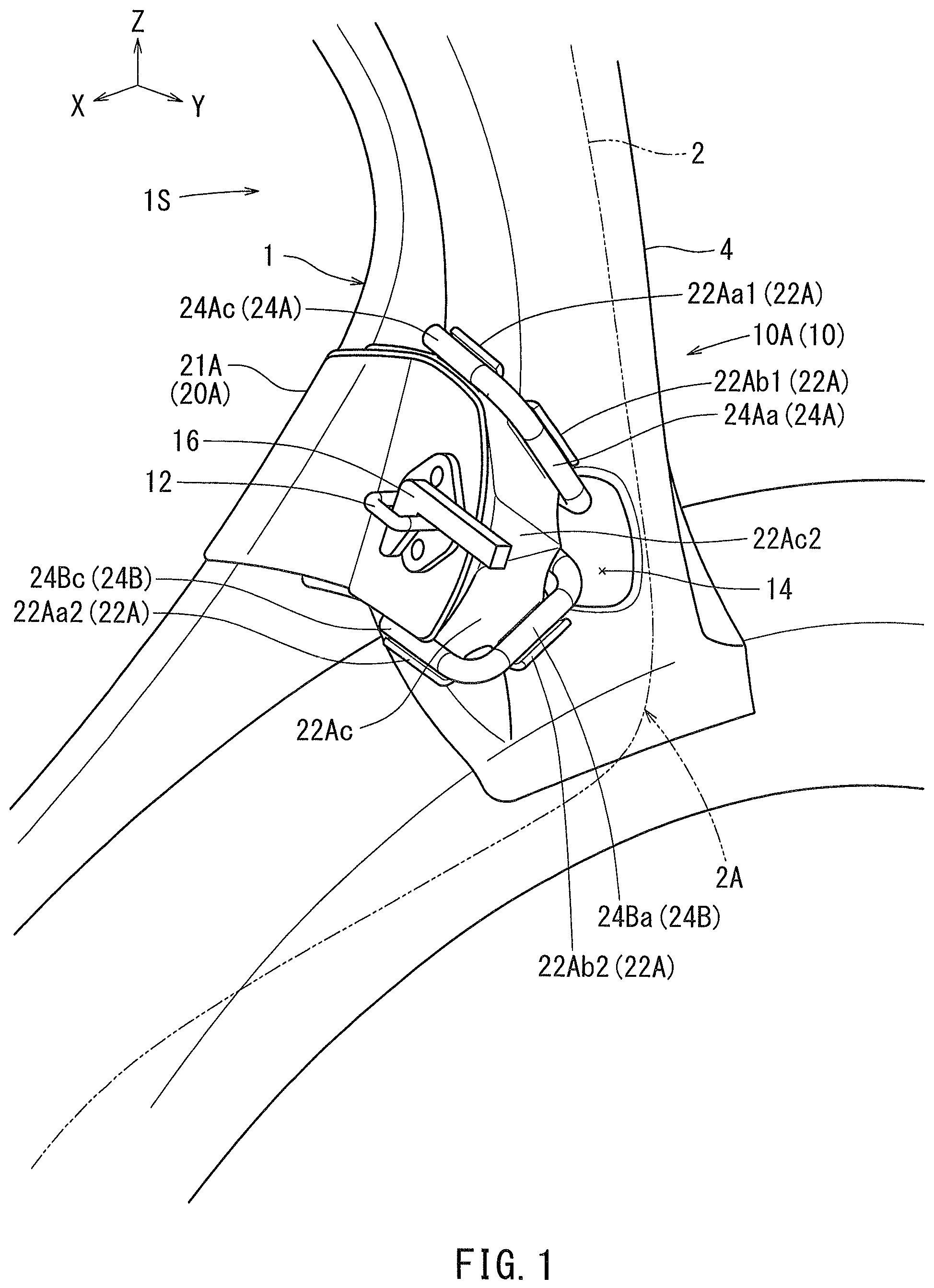
In , an outer panel 18 is not shown. shows a striker mounting structure for a door 2 provided at a left rear side portion 1 S of a vehicle body 1 . A reinforcement 4 may be provided at the rear side portion 1 S of the vehicle body 1 . As shown in , an outer panel 18 may cover the reinforcement 4 , a reinforcement member 20 A, connecting rods 24 A, 24 B, and a reinforcement plate 22 Ac. As also shown in , a striker 12 may not be covered by the outer panel 18 .
A hook 16 may be provided on a door rear end portion 2 A of the door 2 . When the door 2 is closed, the hook 16 may lock in the striker 12 . When the hook 16 is locked in the striker 12 , the striker 12 prevents the door 2 from entering the passenger compartment in the event of a side collision. The below described striker mounting structure 10 A ( 10 ) is configured to allow the striker 12 to be mounted on the vehicle body.
The striker 12 may be mounted on the vehicle body 1 and be one component of a striker mounting unit 10 U. As shown in , the striker mounting unit 10 U may include a striker 12 , a reinforcement member 20 A, connecting rods 24 A, 24 B, bolts BLT, and a nut plate NLT.
As shown in , the reinforcement 4 may be provided with an insertion hole 14 . The insertion hole 14 may open toward a direction away from the passenger compartment, which is the direction opposite to the interior of the passenger compartment. The outer panel 18 may include a striker mounting surface 18 M on the front side thereof.
The striker mounting surface 18 M may be provided so as to be spaced from the reinforcement 4 in the forward/backward direction of the vehicle body.
As shown in , the reinforcement member 20 A may include two reinforcement members 21 A, 22 A. The striker 12 may be fixed to one of the reinforcement members (reinforcement member 20 A in this embodiment). Specifically, the striker 12 may include a striker plate 12 b disposed on the striker mounting surface 18 M (see ) and a striker rod 12 a , which may be substantially U-shaped, projecting from the striker plate 12 b.
A mounting plate portion 21 Aa of the reinforcement member 21 A, shown in , may be disposed on the rear side of the striker mounting surface 18 M, as shown in . The reinforcement member 22 A is disposed on the rear side of the mounting plate portion 21 Aa of the other reinforcement member 21 A. The nut plate NLT is disposed on the rear side of the reinforcement member 22 A. Legs Ba of the bolts BLT are sequentially inserted in holes 12 c in the striker 12 , holes in the striker mounting surface 18 M, and each of the holes 21 Ab, 22 Af in the corresponding reinforcement members 21 A, 22 A. The front ends of the legs Ba of the bolts BLT are screwed into nuts Na provided on the nut plate NLT. In this way, the striker 12 is fixed on the striker mounting surface 18 M, together with the reinforcement member 20 A, using the bolts BLT and nut plate NLT.
Referring to , the reinforcement member 21 A may be formed, for example, in an L-shape in a top view. The reinforcement member 21 A may include a mounting plate portion 21 Aa and a lateral wall 21 Ac rising from one end edge of the mounting plate portion 21 Aa. The mounting plate portion 21 Aa faces the reinforcement 4 , with a gap formed therebetween. The mounting plate portion 21 Aa may have a shape which generally follows a corresponding surface of the reinforcement 4 . Two holes 21 Ab are formed in the mounting plate portion 21 Aa, into which the bolts BLT may be inserted. The reinforcement member 22 A may be formed in a shape to generally conform to the shape of the reinforcement member 21 A. A reinforcement plate 22 Ac may be formed at an end of the reinforcement member 22 A directed toward the outside of the passenger compartment. The reinforcement plate 22 Ac may be oriented in the direction away from the passenger compartment.
As shown in , the connecting rods 24 A, 24 B may have a U-shaped configuration. The connecting rods 24 A, 24 B may respectively include rod portions 24 Aa, 24 Ba, locking portions 24 Ab, 24 Bb, and fixing end portions 24 Ac, 24 Bc. The locking portions 24 Ab, 24 Bb extend from one end of the corresponding rod portions 24 Aa, 24 Ba (for example, ends close to each other, specifically, a lower end of the rod portion 24 Aa and an upper end of the rod portion 24 Ba) in the direction toward the inside of the passenger compartment. The fixing end portions 24 Ac, 24 Bc extend from the other end of the corresponding rod portions 24 Aa, 24 Ba (for example, ends far from each other, specifically, an upper end of the rod portion 24 Aa, a lower end of the rod portion 24 Ba) in the direction toward the inside of the passenger compartment. The locking portions 24 Ab, 24 Bb are inserted in the same insertion hole 14 (see ) formed in the reinforcement 4 . The rod portions 24 Aa, 24 Ba serve to connect the locking portions 24 Ab, 24 Bb with the fixing end portions 24 Ac, 24 Bc.
As shown in , the reinforcement member 22 A may have substantially a Z-shape as viewed from the top. The reinforcement member 22 A may include a plate-like main body 22 Ad, a flange 22 Ae, and a reinforcement plate 22 Ac. The flange 22 Ae extends from an inner edge, which is an edge nearer the passenger compartment, of the plate-like main body 22 Ad in a direction away from the reinforcement 4 (see ), for example, in the forward direction. The flange 22 Ae may be positioned along a passenger compartment inner side of the lateral wall 2 lAc of the reinforcement member 21 A. The reinforcement plate 22 Ac extends from a passenger compartment outer edge of the plate-like main body 22 Ad in a direction toward the reinforcement 4 , for example, in the backward direction.
As shown in , the reinforcement member 22 A may include fixing portions 22 Aa 1 , 22 Aa 2 , 22 Ab 1 , and 22 Ab 2 , to which the connecting rods 24 A, 24 B are configured to be attached. The fixing portions 22 Aa 1 , 22 Aa 2 may extend from opposite ends of the plate-like main body 22 Ad, for example, the upper and lower ends. The fixing portions 22 Aa 1 , 22 Aa 2 may have, for example, a semicircular bottom surface, which conforms to the shape of the fixing end portions 24 Ac, 24 Bc of the connecting rods 24 A, 24 B. The fixing end portions 24 Ac, 24 Bc of the connecting rods 24 A, 24 B are welded to the inner peripheral surfaces of the fixing portions 22 Aa 1 , 22 Aa 2 . The fixing portions 22 Ab 1 , 22 Ab 2 extend from opposite ends of the reinforcement plate 22 Ac, for example, upper and lower ends. The fixing end portions 22 Ab 1 , 22 Ab 2 may have, for example, a semicircular bottom surface, which conforms to the shape of the rod portions 24 Aa, 24 Ba of the connecting rods 24 A, 24 B. The rod portions 24 Aa, 24 Ba of the connecting rods 24 A, 24 B are welded to the inner peripheral surfaces of the fixing portions 22 Ab 1 , 22 Ab 2 .
As shown in , the connecting rods 24 A, 24 B are attached to the reinforcement member 20 A. The locking portions 24 Ab, 24 Bb of the connecting rods 24 A, 24 B project from the reinforcement member 20 A toward the reinforcement 4 . The locking portions 24 Ab, 24 Bb are inserted into the insertion hole 14 formed in the reinforcement 4 . The connecting rods 24 A, 24 B are arranged vertically in the upward/downward direction with respect to each other. The rod portions 24 Aa, 24 Ba of the connecting rods 24 A, 24 B extend in the forward/backward direction. The spacing between the rod portions 24 Aa, 24 Ba gradually reduces in the backward direction.
As shown in , the reinforcement plate 22 Ac may include two ridge lines 22 Ac 1 extending in the forward/backward direction. The reinforcement plate 22 Ac may also include a top portion 22 Ac 2 formed, for example, to have substantially a triangular shape between the ridge lines 22 Ac 1 . The reinforcement plate 22 Ac is raised in the thickness direction, such that the top portion 22 Ac 2 faces away from the passenger compartment. As an alternative to the two ridge lines 22 Ac 1 and the top portion 22 Ac 2 , only one ridge line 22 Ac 1 may be provided. The reinforcement plate 22 Ac is raised in the thickness direction, such that the ridge lines 22 Ac 1 are located outside of the passenger compartment.
, 5 , and 6 illustrate movement of the striker mounting structure 10 A during a side collision. The two-dotted chain lines in indicate the position of the striker 12 before the side collision; the solid lines indicate the position of the striker 12 during a side collision.
As shown in and , in the event of a side collision, the door rear end portion moves toward the front of the vehicle body when, for example, the door is deformed. As a result, the hook 16 (see ) on the door moves forward (in a direction indicated by an arrow). As a result, the hook 16 pulls the striker 12 in the forward direction. The movement of the striker 12 causes the entire reinforcement member 20 A to move in the forward direction of the vehicle body. As the reinforcement member 20 A moves forward, the locking portions 24 Ab, 24 Bb of the connecting rods 24 A, 24 B are moved to abut the edges of the insertion hole 14 formed in the reinforcement 4 . This abutment with the reinforcement 4 prevents the connecting rods 24 A, 24 B from further moving in the forward direction. As indicated in , a reaction force (indicated by the semi-transparent (grey) arrows) in the backward direction of the vehicle body is applied to the connecting rods 24 A, 24 B from the reinforcement 4 . This, plus the abutment with the insertion hole 14 , causes a rotational force to act on the connecting rods 24 A, 24 B, in particular rotation about the fixing end portions 24 Ac, 24 Bc. This and subsequent movements are described in greater detail below.
As shown in , the rod portions 24 Aa, 24 Ba of the connecting rods 24 A, 24 B are angled with respect to the direction in which the load is being applied. The connecting rods 24 A, 24 B thus receive rotational forces about their respective fixing end portions 24 Ac, 24 Bc. These rotational forces enable the locking portions 24 Ab, 24 Bb to move along the front wall edge of the insertion hole 14 of the reinforcement 4 . For instance, one of the locking portions 24 Ab of the connecting rod 24 A moves in the upward direction, so as to be abutted to the upper portion of the hole edge of the insertion hole 14 . The other locking portion 24 Bb of the other connecting rod 24 B moves in the downward direction and is abutted to the lower portion of the hole edge of the insertion hole 14 . As the locking portions 24 Ab, 24 Bb move along the front wall edge of the insertion hole 14 , the fixing portions 22 Ab 1 , 22 Bb 1 begin to be bent by the respective rod portions 24 Aa, 24 Ba. Alternatively or additionally, the top portion 22 Ac 2 of the reinforcement plate 22 Ac may be bent toward the passenger compartment, for instance about the ridge lines 22 Ac 1 . These bending movements help further absorb some of the impact force before it is applied with greater strength to reinforcement member 21 A and/or the reinforcement 4 . When the door further deforms and the striker 12 moves further forward, the reinforcement member 21 A or/and the reinforcement 4 gradually deform(s).
The use of a plurality of connecting rods 24 A, 24 B prevents the striker 12 from being inclined, for instance in the up or down direction, during the side collision. In contrast, if only one connecting rod is provided, as shown in , a striker 112 may be inclined/bent during a side collision about the portion where the striker 112 is locked in the insertion hole 114 , for example due to rotation of the connecting rod 124 . The present embodiment, on the other hand, may prevent such a bending movement of the striker 12 with respect to the insertion hole 14 of the reinforcement 4 . The hook 16 is therefore prevented from being removed from the striker 12 . Accordingly, entry of the door into the passenger compartment may be prevented or delayed, as the reinforcement member 21 A and the reinforcement 4 are gradually deformed during the side collision.
shows a striker mounting structure 10 B ( 10 ) according to a second embodiment. The striker mounting structure 10 B according to the second embodiment may include a reinforcement member 20 B ( 21 A, 22 B) alternative to the reinforcement member 20 A ( 21 A, 22 A) shown in . Additionally, the reinforcement 4 may include two insertion holes 14 A, 14 B, as shown in , in contrast to the one insertion hole 14 shown in .
As shown in , the reinforcement member 22 B may have substantially a Z-shaped configuration in the top view. The reinforcement member 22 B may also include a plate-like main body 22 Bd, a flange 22 Be, and a reinforcement plate 22 Bc. The flange 22 Be extends from the inner edge, closer to the passenger compartment, of the plate-like main body 22 Bd in a direction away from the reinforcement 4 , for example, in the forward direction. The reinforcement plate 22 Bc extends from the outer edge, away from the passenger compartment, of the plate-like main body 22 Bd in a direction toward the reinforcement 4 , for example, in the backward direction.
As shown in , two connecting rods 24 A, 24 B may be attached to the reinforcement member 20 B. The rod portion 24 Aa of the first connecting rod 24 A is fixed along the upper edge of the reinforcement plate 22 Bc. The rod portion 24 Ba of the second connecting rod 24 B is fixed along the lower edge of the reinforcement plate 22 Bc. The interval between the rod portions 24 Aa, 24 Ba gradually increases toward the backward direction. The locking portions 24 Ab, 24 Bb extend from the rear ends of the rod portions 24 Aa, 24 Ba toward the inside of the passenger compartment. The locking portions 24 Ab, 24 Bb are inserted in respective insertion holes 14 A, 14 B of the reinforcement 4 .
As shown in , the locking portions 24 Ab, 24 Bb may be provided at the rear portions of respective connecting rods 24 A, 24 B. The first locking portion 24 Ab is inserted in the first insertion hole 14 A formed in the reinforcement 4 . The second locking portion 24 Bb is inserted in the second insertion hole 14 B formed in the reinforcement 4 .
As shown in , the first and second connecting rods 24 A, 24 B are fixed to an upper portion and a lower portion of the reinforcement plate 22 Bc, respectively. The interval between the rod portions 24 Aa, 24 Ba of the connecting rods 24 A, 24 B gradually increases toward the backward direction. Alternatively, as shown in , the interval between the rod portions 24 Aa, 24 Ba may become smaller toward the backward direction. At least one part of the interval changing part 24 SA of each of the rod portions 24 Aa, 24 Ba, where the interval therebetween changes, are fixed to the reinforcement plate 22 Bc.
As shown in , in the event of a side collision, the door rear end portion may move in the forward direction when the door is deformed. In this case, the hook 16 (see ) formed on the door pulls the reinforcement member 20 B in the forward direction via the striker 12 . This allows the connecting rod 24 A attached to the reinforcement member 20 B to move in the forward direction. The locking portion 24 Ab of the connecting rod 24 A accordingly moves in the forward and downward direction so as to abut a lower front edge of the insertion hole 14 A. The other locking portion 24 Bb of the other connecting rod 24 B accordingly moves in a forward and upward direction so as to abut an upper front edge of the insertion hole 14 B. Further, when the door deforms and the hook 16 pulls the striker 12 still further in the forward direction, the reinforcement member 20 B and/or the reinforcement 4 is/are gradually deformed.
The reinforcement 4 shown in may include two insertion holes 14 A, 14 B. Therefore, the force to be applied to the reinforcement 4 may be dispersed in two spots, as compared with the reinforcement 4 having only one insertion hole 14 as shown in . As a result, the deformation of the reinforcement 4 may be further delayed and the entry of the door in the passenger compartment may be prevented or delayed
shows a striker mounting structure 10 C ( 10 ) according to a third embodiment. The striker mounting structure 10 C may include a reinforcement member 20 C ( 21 A, 22 C), shown in , alternative to the reinforcement members 20 A ( 21 A, 22 A) shown in , 4 .
As shown in , the reinforcement member 22 C may include a plate-like main body 22 Cd, a flange 22 Ce, and a reinforcement plate 22 Cc. The flange 22 Ce extends from the inner edge, the edge nearer the passenger compartment, of the plate-like main body 22 Cd in a direction away from the reinforcement 4 , for example, in the forward direction. In this embodiment, the reinforcement plate 22 Cc is a separate component from the plate-like main body 22 Cd and is attached to the plate-like main body 22 Cd. The reinforcement plate 22 Cc may extend, for example, from an area near the inner edge, an edge nearer the passenger compartment, of the plate-like main body 22 Cd in the direction toward the reinforcement 4 , for example, in the backward direction.
As shown in , the fixing portions 22 Cb 1 , 22 Cb 2 are formed at both of the upper and lower ends of the reinforcement plate 22 Cc. The fixing portions 22 Cb 1 , 22 Cb 2 may include, for example, a semicircular bottom surface, which confoinis to the shape of the rod portions 24 Aa, 24 Ba of the connecting rods 24 A, 24 B. The rod portions 24 Aa, 24 Ba are welded to the inner peripheral surfaces of the fixing portions 22 Cb 1 , 22 Cb 2 .
As shown in , the rod portion 24 Aa of the first connecting rod 24 A extends along the upper edge of the reinforcement plate 22 Cc in the forward/backward direction. The rod portion 24 Ba of the second connecting rod 24 B extends along the lower edge of the reinforcement plate 22 Cc in the forward/backward direction. The interval between the rod portions 24 Aa and 24 Ba, generally located at the interval changing portion 24 SB, gradually becomes smaller in the backward direction. The locking portions 24 Ab, 24 Bb extend from the rear ends of the rod portions 24 Aa, 24 Ba toward the inside of the passenger compartment. The locking portions 24 Ab, 24 Bb are inserted in the insertion hole 14 of the reinforcement 4 .
The shapes of the striker 12 and the hook 16 are not limited to those illustrated in , and may have different shapes as long as the hook can be locked by the striker.
The striker mounting structure 10 may include two connecting rods 24 A, 24 B as shown, for example, in . Alternatively, the striker mounting structure 10 may have three or more connecting rods. One end of each of the three connecting rods may be inserted in one insertion hole formed in the reinforcement 4 . Alternatively, the one end of each of the three connecting rods may be inserted in a plurality of insertion holes formed in the reinforcement 4 .
The reinforcement member 22 A illustrated in , 4 and the reinforcement member 22 B illustrated in may have the plate-like main bodies 22 Ad, 22 Bd and the reinforcement plates 22 Ac, 22 Bc integrally formed as a single member. Alternatively, the reinforcement plates 22 Ac, 22 Bc may be separate components from the plate-like main bodies 22 Ad, 22 Bd and may be attached to the plate-like main bodies 22 Ad, 22 Bd.
The various examples described above in detail with reference to the attached drawings are intended to be representative of the present disclosure and are thus non-limiting embodiments. The detailed description is intended to teach a person of skill in the art to make, use, and/or practice various aspects of the present teachings, and thus does not limit the scope of the disclosure in any manner. Furthermore, each of the additional features and teachings disclosed above may be applied and/or used separately or with other features and teachings in any combination thereof, to provide an improved striker mounting structure, and/or methods of making and using the same.
Figures (9)
Citations
This patent cites (33)
- US4323271
- US4470626
- US4602813
- US4756565
- US4946208
- US4998759
- US6038740
- US6735822
- US6814401
- US7909372
- US8226157
- US8371640
- US8439409
- US10532668
- US10882561
- US20010022456
- US20040093917
- US20050218671
- US20080217932
- US20090250947
- US20100320778
- US20110291442
- US20110316294
- US20140053388
- US20190225276
- US20200284071
- US102004034125
- US102018007926
- US6-40259
- US2001-277854
- US2003-081137
- US2018-138408
- US2019-127262