Abstract
A cover opening-closing device comprises a rod, a casing in which at least a portion of the rod is stored, a lock unit, an interlock mechanism, and a connection unit. The lock unit can rotate about a central axis line between a lock position, in which locking with the cover is possible, and a release position, in which locking is not possible. The interlock mechanism is configured so that the rotation of the lock unit and the displacement of the rod are interlocked. The connection unit is configured so as to connect the lock unit to the casing and to restrict displacement of the lock unit in the direction of the central axis line.
Claims (12)
1. A device for opening and closing a cover body that controls opening and closing of an opening portion, which are achieved by the cover body, wherein the device for opening and closing the cover body comprises a rod, wherein the rod is able to be displaced between a first position and a second position; a casing, wherein the casing contains at least a portion of the rod; a locking portion, wherein the locking portion is able to be displaced rotationally between a lock position and a release position, and the locking portion is able to rotate about a central axis parallel to a displacement direction of the rod, wherein the lock position is a position that is able to be locked with the cover body, and the release position is a position that is not able to be locked with the cover body; a linkage mechanism, wherein the linkage mechanism enables a linkage between a rotational displacement of the locking portion and a displacement of the rod; and a connecting portion, wherein the connecting portion connects the locking portion to the casing, so as to allow the locking portion to rotate between the lock position and the release position and to restrict displacement of the locking portion in a direction of the central axis, wherein the device for opening and closing the cover body further comprises a locking component, wherein the locking component is provided with the locking portion and a through hole through which the rod penetrates, wherein an outer peripheral surface of the rod is referred to as a second surface, and an inner peripheral surface of the through hole is referred to as a first surface, the linkage mechanism has a cam groove disposed on the first surface, and a protrusion portion which is disposed on the second surface and in sliding contact with an inner wall of the cam groove, and a detachment groove is disposed on the first surface, and the detachment groove is branched from the cam groove and extends to an end of the first surface.
9. A device for opening and closing a cover body that controls opening and closing of an opening portion, which are achieved by the cover body, wherein the device for opening and closing the cover body comprises a rod, wherein the rod is able to be displaced between a first position and a second position; a casing, wherein the casing contains at least a portion of the rod; a locking portion, wherein the locking portion is able to be displaced rotationally between a lock position and a release position, and the locking portion is able to rotate taking a central axis parallel to a displacement direction of the rod as a center, wherein the lock position is a position that is able to be locked with the cover body, and the release position is a position that is not able to be locked with the cover body; a linkage mechanism, wherein the linkage mechanism enables the locking portion to be displaced rotationally by using a force that enables the rod to be displaced in a direction parallel to the central axis; and a connecting portion, wherein the connecting portion connects the locking portion to the casing, so as to allow the locking portion to rotate between the lock position and the release position and to restrict displacement of the locking portion in a direction of the central axis, wherein the device for opening and closing the cover body further comprises a locking component, wherein the locking component is provided with the locking portion and a through hole through which the rod penetrates, wherein an outer peripheral surface of the rod is referred to as a second surface, and an inner peripheral surface of the through hole is referred to as a first surface, the linkage mechanism has a cam groove disposed on the first surface, and a protrusion portion which is disposed on the second surface and in sliding contact with an inner wall of the cam groove, and a detachment groove is disposed on the first surface, and the detachment groove is branched from the cam groove and extends to an end of the first surface.
Show 10 dependent claims
2. The device for opening and closing a cover body according to claim 1 , wherein when the locking portion is in the release position, an end of the rod close to the locking portion is closer to the cover body than the locking portion.
3. The device for opening and closing a cover body according to claim 2 , further comprising an alternation mechanism, wherein each time a pressing force F acts on the rod, the alternation mechanism enables the rod to be alternately displaced between the first position and the second position.
4. The device for opening and closing a cover body according to claim 2 , wherein the linkage mechanism enables the locking portion to be rotationally displaced when the locking portion is detached from a locked portion of the cover body, wherein the locked portion is a part of the cover body that is in contact with the locking portion located at the lock position.
5. The device for opening and closing a cover body according to claim 1 , further comprising an alternation mechanism, wherein each time a pressing force F acts on the rod, the alternation mechanism enables the rod to be alternately displaced between the first position and the second position.
6. The device for opening and closing a cover body according to claim 5 , wherein the linkage mechanism enables the locking portion to be rotationally displaced when the locking portion is detached from a locked portion of the cover body, wherein the locked portion is a part of the cover body that is in contact with the locking portion located at the lock position.
7. The device for opening and closing a cover body according to claim 1 , wherein the linkage mechanism enables the locking portion to be rotationally displaced when the locking portion is detached from a locked portion of the cover body, wherein the locked portion is a part of the cover body that is in contact with the locking portion located at the lock position.
8. The device for opening and closing a cover body according to claim 1 , wherein a position of the protrusion portion in the cam groove is configured as a lock position of the protrusion portion, when the locking portion is in the lock position, and a position of the protrusion portion in the cam groove is configured as a release position of the protrusion portion, when the locking portion is in the release position, and a branch portion between the detachment groove and the cam groove is disposed at a position in the cam groove and disposed at a position where it deviates from the lock position of the protrusion portion to the release position of the protrusion portion.
10. The device for opening and closing a cover body according to claim 9 , wherein when the locking portion is in the release position, an end of the rod close to the locking portion is closer to the cover body than the locking portion.
11. The device for opening and closing a cover body according to claim 9 , further comprising an alternation mechanism, wherein each time a pressing force F acts on the rod, the alternation mechanism enables the rod to be alternately displaced between the first position and the second position.
12. The device for opening and closing a cover body according to claim 9 , wherein the linkage mechanism enables the locking portion to be rotationally displaced when the locking portion is detached from a locked portion of the cover body, wherein the locked portion is a part of the cover body that is in contact with the locking portion located at the lock position.
Full Description
Show full text →
CROSS-REFERENCE TO RELATED APPLICATIONS
This application is a 371 U.S. national stage of PCT/JP2019/032702, filed Aug. 21, 2019, which claims priority of Japanese Patent Application No. 2018-157303, filed Aug. 24, 2018, contents of each of which are incorporated by reference.
TECHNICAL FIELD OF THE INVENTION
The present disclosure relates to a device for opening and closing a cover body, which controls opening and closing of an opening portion achieved by a cover body.
BACKGROUND OF THE INVENTION
For example, a device for opening and closing a cover body described in Patent Document 1 has a cylinder-shaped rotation axis, a linear motion axis inserted into the rotation axis and others. The rotation axis can rotate relative to the linear motion axis. The linear motion axis can move integrally with the rotation axis back and forth in the length direction.
The front end of the rotation axis is provided with a locking portion that can be locked with the cover body. The rotation axis moves integrally with the linear motion axis back and forth while rotating relative to the linear motion axis. Thereby, the locking portion is displaced rotationally between latch-up position and non-latch-up position. The latch-up position is a position locking with the cover body, and the non-latch-up position is a position where the locking is released.
PRIOR ART DOCUMENT
Patent Document
• Patent Document 1: Japanese Patent Application Publication No. 2017-43893
SUMMARY OF THE INVENTION
The problem to be solved by the present disclosure
In the technique described in Patent Document 1, when the locking portion is locked with the cover body, if an external force in the direction of opening the cover body acts on the cover body, the external force acts on the linear motion axis via the locking portion and the rotation axis.
The above-mentioned external force acts in the same direction as the displacement direction of the linear motion axis. Therefore, when the locking portion is located at the latch-up position, a mechanism is required to limit the displacement of the linear motion axis due to the external force.
Therefore, in the device for opening and closing a cover body described in Patent Document 1, it is difficult to reduce the number of parts and simplify the structure. In one aspect of the present disclosure, it is desirable to reduce the number of parts and simplify the structure.
The means to address the problem
The device for opening and closing a cover body of one aspect of the present disclosure controls the opening and closing of the opening portion achieved by the cover body. The device for opening and closing a cover body comprises: a rod that can be displaced between the first position and the second position; a casing in which at least a portion of the rod is contained; a locking portion that can be displaced between a lock position and a release position, wherein the locking portion can rotate about a central axis parallel to the displacement direction of the rod, wherein the lock position is a position that can be locked with the cover body, and the release position is a position that cannot be locked with the cover body; a linkage mechanism configured to achieve a linkage between the rotational displacement of the locking portion and the displacement of the rod; and a connecting portion configured to connect the locking portion to the casing, so as to allow the locking portion to rotate between the lock position and the release position and to restrict displacement of the locking portion in the direction of the central axis.
This thus promotes most of “external force in the opening direction (hereinafter, referred to as “external force”)” that acts on the cover body, to act on the casing via the locking portion. That is to say, it is possible to suppress the external force from acting on the rod that can be displaced. Therefore, the number of parts of the device for opening and closing a cover body can be reduced and the structure can be simplified.
BRIEF DESCRIPTION OF THE DRAWINGS
is a diagram showing the device for opening and closing a cover body of the first embodiment.
is a diagram showing the device for opening and closing a cover body of the first embodiment.
is an exploded view showing the alternation mechanism of the first embodiment.
is a diagram showing a release position and a protruding position in the first embodiment.
is a diagram showing a lock position and a containing position in the first embodiment.
is an operation explanatory diagram of the alternation mechanism of the first embodiment.
is an operation explanatory diagram of the alternation mechanism of the first embodiment.
is an operation explanatory diagram of the alternation mechanism of the first embodiment.
is an operation explanatory diagram of the device for opening and closing a cover body of the first embodiment.
is an operation explanatory diagram of the device for opening and closing a cover body of the first embodiment.
is a diagram showing the structure of the connecting portion of the first embodiment.
is a diagram showing a cam groove and a protrusion portion of the first embodiment.
is a diagram showing a cam groove and a protrusion portion of the first embodiment.
is an operation explanatory diagram of the linkage mechanism of the first embodiment.
is an operation explanatory diagram of the linkage mechanism of the second embodiment.
is an operation explanatory diagram of the linkage mechanism of the third embodiment.
REFERENCE SIGNS
•
• 1 : Device for opening and closing a cover body, • 3 : Cover body, • 5 : Rod device, • 7 : Locking device, • 51 : Push rod, • 52 : Rod casing, • 53 : Locking portion, • 53 A: Connecting portion, • 53 B: Locking component, • 53 C: Through hole, • 53 D: Fitting portion, • 53 E: Fitted portion, • 54 : Linkage mechanism, • 54 A: Cam groove, • 54 B: Protrusion portion, • 54 C: Detachment groove, • 55 : Alternation mechanism.
DETAILED DESCRIPTION OF THE INVENTION
The following description shows an example of an embodiment within the technical scope of the present disclosure. That is to say, the present disclosure is not limited to the specific structures, constructions, or others shown in the following embodiments.
In addition, arrows indicating directions marked in each figure are described for easy understanding of the relationship among the figures. The present disclosure is not limited to the directions marked in each figure.
For the components or sites described at least with reference signs, at least one is provided except for the case where “one” is expressed. That is to say, in the cases where “one” is not expressed, two or more of these components may be provided.
The First Embodiment
1. Overview of the Device for Opening and Closing a Cover Body
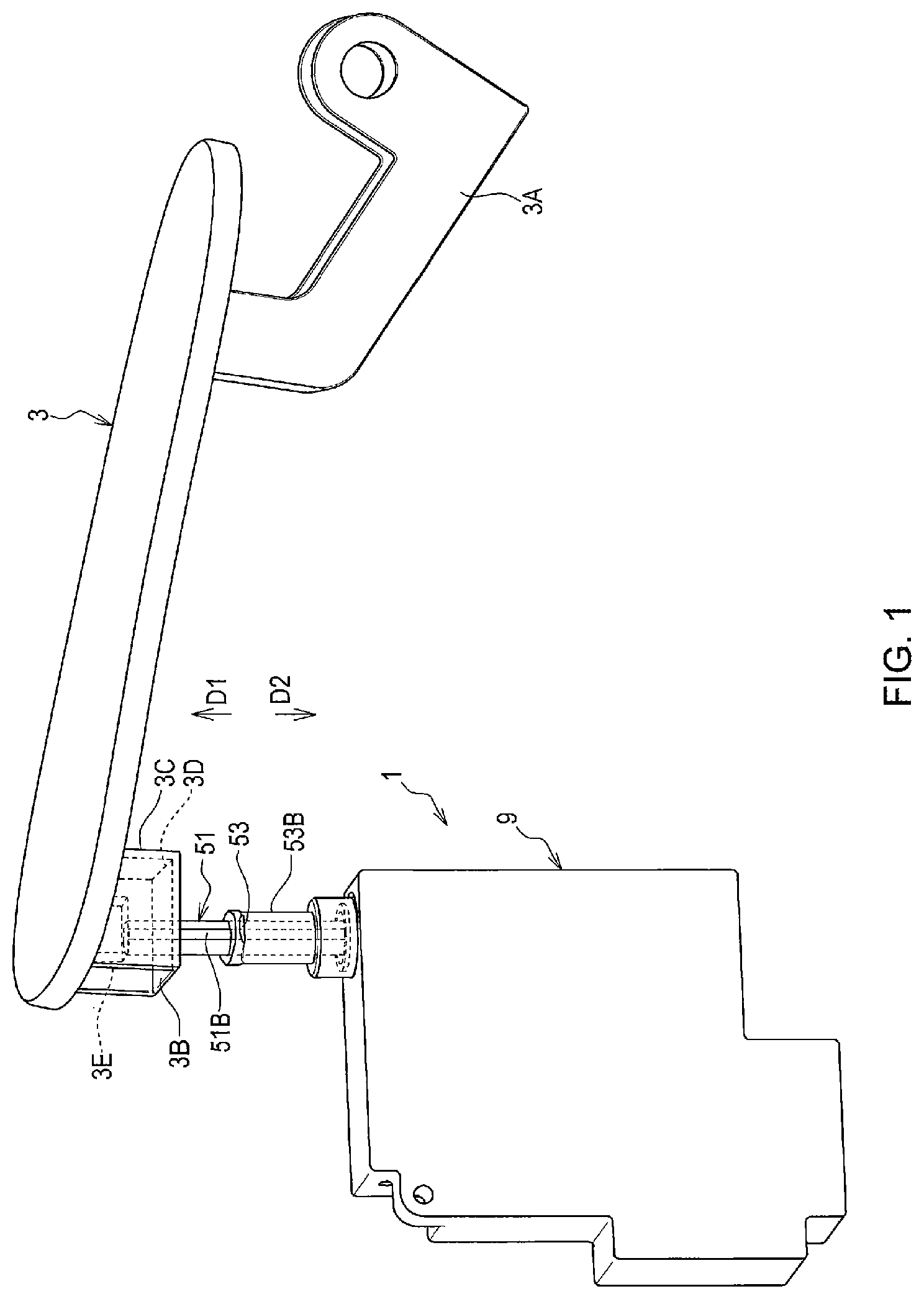
In the first embodiment, an example of the device for opening and closing a cover body of the present disclosure is applicable to a vehicle. Specifically, as shown in , the device for opening and closing a cover body 1 , as an example, controls the opening and closing actions of the cover body 3 .
The cover body 3 is an example of a closing body that opens and closes a fuel filler (not shown in drawings) of a vehicle. The fuel filler is an example of the opening portion. The fuel filler is disposed on the outer panel (not shown in drawings) of the vehicle. The cover body 3 is mounted on the outer plate through the hinge portion 3 A. The cover body 3 can be rotated relative to the outer plate centering on an imaginary line perpendicular to the paper surface of .
2. Structure of the Device for Opening and Closing a Cover Body
2.1 Overview of the Device for Opening and Closing a Cover Body
As shown in , the device for opening and closing a cover body 1 at least has a rod device 5 and a locking device 7 . The rod device 5 controls the opening and closing actions of the cover body 3 . The locking device 7 restricts the movement of the rod device 5 .
2.2 the Structure of the Rod Device
As shown in , the rod device 5 at least has a push rod 51 , a rod casing 52 , a locking portion 53 , a linkage mechanism 54 (refer to ), an alternation mechanism 55 , and the like.
<Push Rod>
The push rod 51 is a rod-shaped component that is displaced between the protruding position (refer to ) and the containing position (refer to ). Each time when receiving a pressing force F (refer to ), the push rod 51 is alternately displaced between the protruding position and the containing position (hereinafter, also referred to as alternate displacement).
That is to say, if the push rod 51 receives the pressing force F when it is in the protruding position, it will be displaced to the containing position due to the action of the pressing force F. If the push rod 51 receives the pressing force F when it is in the containing position, it will be displaced to the protruding position due to the action of the elastic force of the spring 55 A (refer to ).
As shown in , in the protruding position, the part 51 A of the push rod 51 protrudes from the rod casing 52 . As shown in , in the containing position, at least a part of the part 51 A is contained in the rod casing 52 .
In addition, the protruding position is an example of the first position. The containing position is an example of the second position. The pressing force F is, for example, a force acting in the length direction of the push rod 51 .
The rod casing 52 is a cylindrical component having an insertion hole (not shown in drawings), and the push rod 51 can be inserted into the insertion hole by going in and out. The sectional shape of the insertion hole can enable the push rod 51 only to rotate around the central axis Lp (refer to ).
The sectional shape is, for example, substantially D-shaped. The substantially D-shaped shape has an arc portion and a straight-line portion, and the straight-line portion connects both ends of the arc portion. Moreover, a flat portion 51 B (refer to ) is disposed at a site corresponding to the straight-line portion on the push rod 51 .
Therefore, each time the pressing force F is received, the push rod 51 , parallel to the central axis Lp, is displaced back and forth between the protruding position and the containing position, without rotating around the central axis Lp. In other words, the flat portion 51 B constitutes a restriction portion that restricts the rotation of the push rod 51 . In addition, the central axis Lp coincides with the central axis of the push rod 51 .
<Alternation Mechanism>
The alternation mechanism 55 enable the push rod 51 to be alternately displaced. As shown in , this alternation mechanism 55 at least has a spring 55 A, a first cam 55 B, a second cam 55 C, a restriction cylinder 55 D and an axis component 55 E, among others.
The spring 55 A can generate an elastic force towards the upper direction of the paper surface in . The “upper direction of the paper surface in ” refers to the direction from the containing position to the protruding position. Hereinafter, this direction is referred to as “protruding direction D 1 ”. The direction opposite to the protruding direction D 1 is referred to as “containing direction D 2 ”.
As shown in , the axis component 55 E can be rotationally inserted in the first cam 55 B and the second cam 55 C. The axis component 55 E rotates around the central axis Lp, and is integrated into the push rod 51 by fixing techniques such as press-fitting.
In other words, the first cam 55 B and the second cam 55 C can be integrated with the push rod 51 by means of rotating about the central axis Lp. At least one (as an example, three) protrusion portion 55 F is disposed on the outer peripheral surface of the first cam 55 B.
At least one protrusion portion 55 G is also disposed on the outer peripheral surface of the second cam 55 C. In the first embodiment, as an example, the number of protrusion portions 55 G is the same as the number of protrusion portions 55 F. Each protrusion portion 55 F and each protrusion portion 55 G respectively protrude from the outer peripheral surface in a direction perpendicular to the central axis Lp.
As shown in , slot portions 55 J of the same number as the number of the protrusion portions 55 G are disposed on the outer peripheral wall 55 H of the restriction cylinder 55 D. These slot portions 55 J extend in parallel with the central axis Lp to one end (hereinafter, referred to as the first end) of the restriction cylinder 55 D. Each slot portion 55 J is open at the first end.
Each protrusion portion 55 F is fitted into each slot portion 55 J, and each protrusion portion 55 F can be displaced within the slot portion 55 J in the extending direction of the slot portion 55 J (refer to to 8 ). That is to say, the first cam 55 B is displaced in the direction of the central axis Lp rather than rotating about the central axis Lp.
Each protrusion portion 55 G can be displaced between a fitting position and a detachment position. The fitting position is the position where each protrusion portion 55 G is fitted into any one of slot portions 55 J (refer to ), and the detachment position is the position where each protrusion portion 55 G is detached from the slot portion 55 J (refer to ). That is to say, when each protrusion portion 55 G is located in a position to fit into any one of the slot portions 55 J, the second cam 55 C is displaced in the direction of the central axis Lp rather than rotating around the central axis Lp.
When each protrusion portion 55 G is detached from the slot portion 55 J, the second cam 55 C can rotate about the central axis Lp. At the first end of the restriction cylinder 55 D, the open end of each slot portion 55 J is disposed, and at least one locking protrusion portion 55 K that can be locked with each protrusion portion 55 G is provided
Each locking protrusion portion 55 K protrudes in the containing direction D 2 from the first end of the restriction cylinder 55 D. Moreover, in a state in which any one of the protrusion portions 55 G is locked with any one of the locking protrusion portions 55 K to be locked (hereinafter referred to as a locking state), the rotation of the second cam 55 C is restricted.
The position of the bottom of each locking protrusion portion 55 K deviates towards the protruding direction D 1 from the open end of each slot portion 55 J. A spring 55 A always presses the second cam 55 C in the protruding direction D 1 . Therefore, in the state shown in , the elastic force of the spring 55 A can maintain the locking state between the protrusion portion 55 G and the locking protrusion portion 55 K.
As shown in , the first cam 55 B and the second cam 55 C can perform a function of converting the pressing force F in the containing direction D 2 into a rotating force Fr. The rotating force Fr enables the second cam 55 C to be rotated in the direction of the arrow in .
In other words, at least one inclined surface 55 L is disposed (in the first embodiment, as an example, several are disposed) in the first cam 55 B. At least one inclined surface 55 M is disposed (in the first embodiment, as an example, several are disposed) in the second cam 55 C.
The inclined surfaces 55 L and 55 M are inclined with respect to the direction of the pressing force F. The inclination direction of each inclined surface 55 L, 55 M is adjusted so that when the inclined surface 55 L is in contact with the inclined surface 55 M, the component force of the pressing force F generated on the inclined surface 55 M becomes the rotating force Fr.
<Locking Portion>
The locking portion 53 can be rotationally displaced between the lock position (refer to ) and the release position (refer to ). As shown in , in the lock position, the locking portion 53 can be locked with a locked portion 3 B. As shown in , in the release position, the locking portion 53 cannot be locked with the locked portion 3 B.
In other words, the locking portion 53 can rotate around a central axis parallel to the displacement direction of the push rod 51 . The displacement direction of the push rod 51 is parallel to the center axis Lp of the push rod 51 .
In addition, in the first embodiment, the rotation central axis of the locking portion 53 coincides with the central axis Lp of the push rod 51 . Therefore, in the following description, the rotation central axis of the locking portion 53 is also referred to as the central axis Lp.
The device for opening and closing a cover body 1 of the first embodiment has two locking portions 53 (first and second locking portion 53 ). The locking portions 53 are disposed at symmetrical positions across the central axis Lp. In other words, relative to the second locking portion 53 , the first locking portion 53 is offset by approximately 180 degrees in the circumferential direction centering on the central axis Lp.
The locked portion 3 B is disposed on the cover body 3 . This locked portion 3 B has a surface intersecting the central axis Lp. In the first embodiment, as an example, the locked portion 3 B is integrated with the cover body 3 by a box-shaped locked body 3 C.
The part of the locked body 3 C facing the push rod 51 is at least provided with a through hole 3 D through which the push rod 51 can penetrate. The locked portion 3 B is disposed at the outer edge of the through hole 3 D. In addition, in the first embodiment, the locked portions 3 B are respectively disposed at two positions across the through hole 3 D.
In other words, in the cover body 3 of the first embodiment, two locked portions 3 B (the first and second locked portions 3 B) are disposed. Relative to the second locked portion 3 B, the first locked portion 3 B is offset by approximately 180 degrees in the circumferential direction centering on the central axis Lp.
As shown in , the two locking portions 53 are connected to the rod casing 52 through the connecting portion 53 A. The connecting portion 53 A allows the two locking portions 53 to rotate between the lock position and the release position, and restricts the displacement of the locking portions 53 in the direction of the central axis Lp.
In other words, the two locking portions 53 are disposed at the second end of the cylindrical locking component 53 B in the axial direction. The locking component 53 B is provided with a through hole 53 C penetrated by the push rod 51 . Furthermore, as an example, the two locking portions 53 and the locking component 53 B are integrated, and they are resin products or metal products.
A fitting portion 53 D is disposed at the first end of the locking component 53 B in the axial direction, and the fitting portion 53 D is included in the connecting portion 53 A. The fitting portion 53 D is locked with the fitted portion 53 E disposed on the rod casing 52 by means of fitting (or imbedding).
Thereby, the two locking portions 53 , namely the locking component 53 B, and the rod casing 52 are connected in a way of being able to rotate. In other words, the two locking portions 53 , namely the locking component 53 B, are supported by the rod casing 52 .
<Linkage Mechanism>
The linkage mechanism 54 enables a linkage between the rotational displacement of the two locking portions 53 and the reciprocation displacement of the push rod 51 . As shown in , the linkage mechanism 54 of the first embodiment has a cam groove 54 A, a protrusion portion 54 B, and the like.
The cam groove 54 A is a guide groove, and the cam groove 54 A is disposed on either surface of the outer peripheral surface of the push rod 51 and the inner peripheral surface of the through hole 53 C (in the first embodiment, on the inner peripheral surface 53 F of the through hole 53 C). The protrusion portion 54 B is disposed on the other surface (in the first embodiment, on the outer peripheral surface of the push rod 51 ).
The protrusion portion 54 B protrudes from the outer peripheral surface of the push rod 51 to the inner peripheral surface 53 F, and is in sliding contact with the inner wall of the cam groove 54 A. The protrusion portion 54 B of the first embodiment is a hemispherical protrusion.
As shown in , the cam groove 54 A constitutes a closed annular guide groove. In other words, if the protrusion portion 54 B is displaced in one direction within the cam groove 54 A, the protrusion portion 54 B is displaced by means of surrounding the inner peripheral surface 53 F.
The vertical direction of the paper surface in is a direction parallel to the central axis Lp (hereinafter referred to as the axial direction). When the protrusion portion 54 B moves in a part of the cam groove 54 A that is parallel to the vertical direction of the paper surface (hereinafter referred to as the axial groove), the push rod 51 moves in the axial direction, and the locking component 53 B does not rotate relative to the push rod 51 .
When the protrusion portion 54 B moves in a part of the cam groove 54 A that is inclined with respect to the vertical direction of the paper surface (hereinafter referred to as a radial groove), the push rod 51 moves in the axial direction, and the locking component 53 B rotates relative to the push rod 51 .
Therefore, when the protrusion portion 54 B is in the radial groove, if the push rod 51 performs reciprocation displacement, the locking component 53 B, namely the two locking portions 53 , performs rotational displacement interlocked with the reciprocation displacement of the push rod 51 . In other words, the linkage mechanism 54 enables the two locking portions 53 to be rotationally displaced by using the force that enables the push rod 51 to be displaced in the axial direction.
As shown in , the cam groove 54 A, namely the linkage mechanism 54 , is configured to enable the locking portion 53 to be rotationally displaced when the locking portion 53 is away from the locked portion 3 B. In addition, “when the locking portion 53 is away from the locked portion 3 B” refers to the time when the contact surface pressure of the locking portion 53 and the locked portion 3 B is lower than the preset upper limit.
Therefore, even if the locking portion 53 is in contact with the locked portion 3 B, when the contact surface pressure of the locking portion 53 and the locked portion 3 B is lower than the upper limit, it is equivalent to “when the locking portion 53 is away from the locked portion 3 B”.
Furthermore, as shown in , at least when the locking portion 53 is in the release position, the second end 51 C of the push rod 51 is located closer to the cover body 3 than the locking portion 53 . In addition, the second end 51 C refers to an end of the push rod 51 on the side of locking portion 53 in the length direction.
That is to say, when the locking portion 53 is in the release position, the push rod 51 penetrates through the through hole 53 C of the locking component 53 B, and the second end 51 C of the push rod 51 contacts or is close to a part 3 E of the cover body 3 .
As shown in , the inner peripheral surface 53 F is provided with a detachment groove 54 C that branches from the cam groove 54 A and extends to the first end (the lower end of the paper surface of ) of the inner peripheral surface 53 F. The first end is the side opposite to the second end of the locking component 53 B where the locking portion 53 is disposed.
In the cam groove 54 A, the branch portion leading to the detachment groove 54 C is disposed at a position deviating from the “lock position of the protrusion portion 54 B” to the side of “release position of the protrusion portion 54 B” (in other words, the side where the protrusion portion 54 performs rotational displacement in response to the application of the pressing force F).
The “lock position of the protrusion portion 54 B” refers to the position of the protrusion portion 54 B in the cam groove 54 A when the two locking portions 53 are in the lock position. The “release position of the protrusion portion 54 B” refers to the position of the protrusion portion 54 B in the cam groove 54 A when the two locking portions 53 are in the release position.
In addition, in the cam groove 54 A, the position of the branch portion of the first embodiment is a position deviating towards the release position compared to that equivalent to the position of the bottom dead center described hereunder. In other words, the branch portion deviates to the release position compared to the “position in the cam groove 54 A of the protrusion portion 54 B that is most displaced in the containing direction D 2 , when the protrusion portion 54 B is displaced from the lock position to the release position”.
<Locking Device>
The locking device 7 functions to keep the push rod 51 in the containing position. Specifically, as shown in , the locking device 7 at least has a lock rod 7 A and the like.
The lock rod 7 A penetrates the rod casing 52 and is fitted into the push rod 51 . The push rod 51 is provided therein with a recess 51 D into which the lock rod 7 A is fitted (see ). If the lock rod 7 A is fitted into the recess 51 D, the push rod 51 does not move.
That is, as shown in , the rod casing 52 is fixed to the main casing 9 . The main casing 9 is fixed to a vehicle. The lock rod 7 A can be displaced between the position where it is fitted into the recess 51 D and the position where it is detached from the recess 51 D.
The lock rod 7 A is integrated with a helical rack 7 B. The helical rack 7 B can be displaced in a direction perpendicular to the length direction of the rod casing 52 . The helical rack 7 B performs displacement by receiving a force from a helical gear 7 C.
The helical gear 7 C can be rotated by a rotational force from a worm rod 7 D. The worm rod 7 D is driven to rotate by an electric motor 7 E. In the first embodiment, the electric motor 7 E, namely the locking device 7 , operates interlocked with a lockup device (not shown in drawings) of a door (not shown in drawings) for alighting and boarding.
Specifically, the electric motor 7 E operates in such a manner that if the lockup device becomes into a locked state, the lock rod 7 A is fitted into the recess 51 D, and if the lockup device becomes into an unlocked state, the lock rod 7 A is detached from the recess 51 D.
3. Action of Device for Opening and Closing
3.1 Action of the Alternation Mechanism
Each time the pressing force F acts on the push rod 51 , the alternation mechanism 55 enables the push rod 51 to be displaced alternately between the protruding position and the containing position. shows the alternation mechanism 55 in the case where the push rod 51 is in the protruding position.
If the pressing force F acts on the push rod 51 which is in the protruding position (refer to ), each protrusion portion 55 F and each protrusion portion 55 G are respectively fitted into any one of the multiple slot portions 55 J, and are displaced in the direction of the pressing force F, namely the containing direction D 2 .
When each protrusion portion 55 G reaches the open end of each slot portion 55 J (see ), each protrusion portion 55 G rotates about the central axis Lp by means of the rotational force Fr acting on the second cam 55 C.
Thereby, each protrusion portion 55 G is clamped with any one of the locking protrusion portions 55 K, to become into a clamped state (refer to ). At this time, since this clamped state is maintained by the elastic force of the spring 55 A, the push rod 51 is maintained in the containing position.
If the pressing force F acts on the push rod 51 (refer to ) located in the containing position, the second cam 55 C is displaced in the containing direction D 2 , and each protrusion portion 55 G is detached from each locking protrusion portion 55 K.
At this time, by means of the rotational force Fr acting on the second cam 55 C, each protrusion portion 55 G rotates about the central axis Lp along the guiding portion 55 N. Therefore, each protrusion portion 55 G is guided to the open end of any one of the slot portions 55 J.
Furthermore, if the pressing force F disappears, each protrusion portion 55 F and each protrusion portion 55 G are fitted into any one of the multiple slot portions 55 J, and are displaced in the protrusion direction D 1 by the elastic force of the spring 55 A, and thus the push rod 51 returns to the protrusion position.
In addition, the guiding portion 55 N is an inclined surface disposed at the first end of the restriction cylinder 55 D. The guiding portion 55 N is inclined in the same direction as the inclined surfaces 55 L and 55 M. As shown in , the top portion 55 P of each protrusion portion 55 G is a smooth curved surface.
That is to say, as shown in to 8 , after the push rod 51 is displaced in the containing direction D 2 when receiving the pressing force F, the push rod 51 is in the containing position or the protruding position. Hereinafter, the following moment is defined as “the push rod 51 is located at the bottom dead center”, that is, when the push rod 51 is displaced between the containing position and the protruding position, the moment at which the push rod 51 is most displaced toward the containing direction D 2 .
3.2 Action of the Locking Portion and the Locking Component
As shown in , when the push rod 51 is at the protruding position, the two locking portions 53 are located at the release position. Meanwhile, the linkage mechanism 54 and the locking component 53 B are shown by A in .
When the push rod 51 is located at the protruding position, if the pressing force F acts on the push rod 51 , the protrusion portion 54 B and the push rod 51 are integrally displaced towards the containing direction D 2 . In other words, the protrusion portion 54 B is displaced in the axial groove of the cam groove 54 A (refer to B in ).
The source of the pressing force F is the force of a user such as a driver pressing towards the direction of closing the cover body 3 . Therefore, when the push rod 51 is at the protruding position, when the pressing force F acts on the push rod 51 , generally, the cover body 3 together with the push rod 51 is displaced towards a direction of closing the fuel filler.
In addition, the force of a user pressing the cover body 3 is transmitted to the push rod 51 via a pressing portion 3 E which is a part of the cover body 3 . The pressing portion 3 E is disposed on the side of the push rod 51 of the cover body 3 . The pressing portion 3 E of the first embodiment is located in the locked body 3 C.
If the push rod 51 approaches the bottom dead center, the two locking portions 53 approach the cover body 3 by penetrating the through hole 3 D, and the two locking portions 53 are separated from the two locked portions 3 B. At this time, since the protrusion portion 54 B enters the radial groove of the cam groove 54 A, the two locking portions 53 , namely the locking component 53 B, start rotational displacement (refer to C in ).
In addition, in the first embodiment, during the period when the two locking portions 53 are separated from the two locked portions 3 B, the locking component 53 B rotates from before the push rod 51 reaches the bottom dead center to after the push rod 51 reaches the bottom dead center.
After the push rod 51 reaches the bottom dead center, the push rod 51 is displaced in the protruding direction D 1 and is in the containing position (refer to D in ). As shown in , if the push rod 51 is in the containing position, the cover body 3 remains in a position of closing the fuel filler because the two locking portions 53 are in the locking position, and the two locking portions 53 and the two locked portions 3 B become into a locked state.
If the pressing force F acts on the push rod 51 shown in , the push rod 51 is displaced towards the protruding position after being displaced to the bottom dead center. At this time, since the protrusion portion 54 B moves in the radial groove of the cam groove 54 A, the two locking portions 53 are rotationally displaced.
In other words, during the separation period, from before the push rod 51 reaches the bottom dead center to after the push rod 51 reaches the bottom dead center, the locking component 53 B rotates (refer to E in and F in ).
As a result, the two locking portions 53 are restored from the lock position to the release position. At this time, since the protrusion portion 54 B is displaced towards the protruding direction D 1 inside the axial groove of the cam groove 54 A, the cover body 3 is pressed by the push rod 51 towards the direction of opening the fuel filler.
Furthermore, in the first embodiment, every time the pressing force F acts, the locking component 53 B rotates by 90 degrees in the same direction. That is to say, every time the pressing force F acts, the locking component 53 B is alternately displaced between the release position and the lock position while rotating in one direction.
4. Features of the Device for Opening and Closing a Cover Body of the First Embodiment
The device for opening and closing a cover body 1 has a connecting portion 53 A that connects the two locking portions 53 with the rod casing 52 . As a result, the external force acting on the cover body 3 in the opening direction acts on the rod casing 52 via the two locking portions 53 and does not directly act on the push rod 51 . In other words, the external force does not directly act on the push rod 51 that can be displaced. Therefore, the number of components of the device for opening and closing a cover body 1 can be reduced and the structure can be simplified.
When the two locking portions 53 are located at the release position, the second end 51 C of the push rod 51 is closer to the cover body 3 than the two locking portions 53 . Thereby, the cover body 3 can be pressed in the direction of opening the cover body 3 by the push rod 51 .
The device for opening and closing a cover body 1 has an alternate mechanism 55 , and each time a pressing force acts on the push rod 51 , the alternate mechanism 55 enables the push rod 51 to be alternately displaced between the first position and the second position. As a result, the push rod 51 can be easily undergo reciprocation displacement.
When the two locking portions 53 are separated from the two locked portions 3 B, the linkage mechanism 54 enables the two locking portions 53 to be rotationally displaced. Thereby, the rotational force required for the rotational displacement of the two locked portions 3 B is reduced, and the wear of the two locking portions 53 and the two locked portions 3 B is suppressed.
Provided that when the two locking portions 53 are in contact with the two locked portions 3 B, i.e., when the contact surface pressure is greater than the upper limit, if the two locking portions 53 are rotationally displaced, the rotational force required for the rotational displacement of the two locked portions 3 B increases, and the two locking portions 53 and the two locked portions 3 B are worn out in advance.
A detachment groove 54 C is disposed in the inner peripheral surface 53 F of the locking component 53 B. The detachment groove 54 C branches from the cam groove 54 A and extends to the first end of the inner peripheral surface 53 F. Thus, when the two locking portions 53 are in the lock position, users can forcibly open the cover body 3 even if the linkage mechanism 54 , the alternation mechanism 55 , or the locking device 7 fails.
In other words, in order to forcibly open the cover body 3 , it is necessary that the locking component 53 B can be detached from the push rod 51 . Should the detachment groove 54 C be not provided, the locking component 53 B could not be separated from the push rod 51 since the protrusion portion 54 B of the locking component 53 B was locked on the push rod 51 .
Reversely, in the device for opening and closing a cover body 1 of the first embodiment, since the detachment groove 54 C is provided, the locking component 53 B can be separated from the push rod 51 by means of the protrusion portion 54 B passing through the detachment groove 54 C. Therefore, the cover body 3 can be forcibly opened. In addition, the connection strength of the connecting portion 53 A is set so that when a force with a magnitude larger than preset value is applied to the locking component 53 B, the connection between the locking component 53 B and the rod casing 52 can be released.
The branch portion leading to the detachment groove 54 C is disposed at a position deviating from the “lock position of the protrusion portion 54 B” to the “release position of the protrusion portion 54 B” in the cam groove 54 A. Therefore, when users forcibly open the cover body 3 , the protrusion portion 54 B can be reliably introduced into the detachment groove 54 C.
The Second Embodiment
In the first embodiment, during the period in which the two locking portions 53 are separated from the two locked portions 3 B, the locking component 53 B rotates from before the push rod 51 reaches the bottom dead center to after the push rod 51 reaches the bottom dead center.
Compared to the above case, as shown in , in the second embodiment, when the push rod 51 is displaced from the protruding position to the containing position, during the separation period, the locking component 53 B rotates after the push rod 51 reaches the bottom dead center.
<Action of the Locking Portion and the Locking Component>
When the push rod 51 is at the protruding position (refer to A in ), if the pressing force F acts on the push rod 51 , the protrusion portion 54 B and the push rod 51 are displaced in the containing direction D 2 integrally.
Before the push rod 51 reaches the bottom dead center, the protrusion portion 54 B is displaced inside the axial groove of the cam groove 54 A (refer to B in and C in ). After the push rod 51 reaches the bottom dead center, the protrusion portion 54 B enters the radial groove of the cam groove 54 A (refer to D in ).
In other words, during the separation period, before the push rod 51 reaches the bottom dead center, the locking component 53 B does not rotate, while the locking component 53 B rotates after the push rod 51 reaches the bottom dead center.
After the push rod 51 reaches the bottom dead center, the push rod 51 is displaced in the protruding direction D 1 and is in the containing position. If the push rod 51 is in the containing position, the cover body 3 can be maintained in the position of closing the fuel filler since the two locking portions 53 are in locked position and the two locking portions 53 and the two locked portions 3 B become into a locked state.
When the push rod 51 is in the containing position, if the pressing force F acts on the push rod 51 , the push rod 51 is displaced to the protruding position after displaced to the bottom dead center. At this time, since the protrusion portion 54 B moves in the radial groove of the cam groove 54 A, the two locking portions 53 are rotationally displaced.
That is to say, during the separation period, from before the push rod 51 reaches the bottom dead center to after the push rod 51 reaches the bottom dead center, the locking component 53 B rotates (refer to E in and F in ).
As a result, the two locking portions 53 are restored from the lock position to the release position. At this time, since the protrusion portion 54 B is displaced in the protruding direction D 2 inside the axial groove of the cam groove 54 A, the cover body 3 is pressed by the push rod 51 in the direction of opening the fuel filler.
In addition, the same constituent elements as those in the first embodiment are denoted by the same reference signs as those in the first embodiment, and descriptions of the same structures as those in the first embodiment are omitted.
The Third Embodiment
In the first embodiment, during the separation period in which the two locking portions 53 are separated from the two locked portions 3 B, from before the push rod 51 reaches the bottom dead center to after the push rod 51 reaches the bottom dead center, the locking component 53 B rotates.
Compared to the above case, as shown in , in the third embodiment, when the push rod 51 is displaced from the protruding position to the containing position, the locking component 53 B rotates, during the separation period, before the push rod 51 reaches the bottom dead center.
<Actions of the Locking Portion and the Locking Component>
When the push rod 51 is at the protruding position (refer to A in ), if the pressing force F acts on the push rod 51 , the protrusion portion 54 B and the push rod 51 are integrally displaced in the containing direction D 2 .
The protrusion portion 54 B is displaced inside the radial groove (refer to C in ) after the protrusion portion is displaced in axial groove of the cam groove 54 A (refer to B in ) and before the push rod 51 reaches the bottom dead center. After the push rod 51 reaches the bottom dead center, the protrusion portion 54 B is displaced in the protrusion direction D 1 inside the axial groove.
That is to say, during the separation period, the locking component 53 B rotates before the push rod 51 reaches the bottom dead center, and does not rotate after the push rod 51 reaches the bottom dead center.
After the push rod 51 reaches the bottom dead center, the push rod 51 is displaced in the protruding direction D 1 and is in the containing position. If the push rod 51 is in the containing position, the two locking portions 53 are in the lock position, and the cover body 3 can be maintained in the position of closing the fuel filler since the two locking portions 53 and the two locked portions 3 B become into a locked state.
When the push rod 51 is in the containing position, if the pressing force F acts on the push rod 51 , the push rod 51 is displaced to the protruding position after being displaced to the bottom dead center. At this time, since the protrusion portion 54 B moves inside the radial groove of the cam groove 54 A, the two locking portions 53 are rotationally displaced.
In other words, during the separation period, from before the push rod 51 reaches the bottom dead center to after the push rod 51 reaches the bottom dead center, the locking component 53 B rotates (refer to E in and F in ).
As a result, the two locking portions 53 are restored from the lock position to the release position. At this time, since the protrusion portion 54 B is displaced towards the protruding direction D 2 inside the axial groove of the cam groove 54 A, the cover body 3 is pressed by the push rod 51 in the direction of opening the fuel filler.
In addition, the same constituent elements as those of the first and second embodiments are denoted by the same reference signs as those of the first and second embodiments, and descriptions of the same structures as those of the first and second embodiments are omitted.
Other Embodiments
In the first to third embodiments, the device for opening and closing a cover body 1 has two locking portions 53 . However, the present disclosure is not limited to this, i.e., the device for opening and closing a cover body 1 may have, for example, one or three or more locking portions 53 .
In the first to third embodiments, the pressing portion 3 E is in contact with the push rod 51 . However, the present disclosure is not limited to this. That is, for example, the pressing portion 3 E may not be provided.
In the first to third embodiments, when the two locking portions 53 are in the release position, the second end 51 C of the push rod 51 is closer to the cover body 3 than the two locking portions 53 .
However, the present disclosure is not limited to this. That is, for example, when the two locking portions 53 are in the release position, the second end 51 C of the push rod 51 may be closer to the rod casing 52 than the two locking portions 53 .
In the first to third embodiments, the push rod 51 penetrates the through hole 53 C of the locking component 53 B. However, the present disclosure is not limited to this. That is, for example, the push rod 51 may not penetrate the locking component 53 B, but may be located at a position where the central axis of the push rod 51 is deviated from the central axis of the locking component 53 B.
The linkage mechanism 54 of the first to third embodiments uses a force that enables the push rod 51 to be displaced parallel to the central axis Lp, to enable the two locking portions 53 to be rotationally displaced. However, the present disclosure is not limited to this.
In other words, the linkage mechanism 54 of the first to third embodiments is a reversible mechanism. That is to say, when the protrusion portion 54 B is located in the radial groove and when the locking component 53 B is forcibly rotationally displaced, the linkage mechanism 54 enables the push rod 51 to be displaced in the axial direction interlocked with the rotational displacement.
Therefore, the linkage mechanism 54 enables the push rod 51 to be displaced by utilizing the force applied to the locking component 53 B to rotate the locking component 53 B.
The connecting portion 53 A of the first to third embodiments connects the locking portion 53 , namely the locking component 53 B, and the rod casing 52 . However, the present disclosure is not limited to this.
That is, for example, the connecting portion 53 A may connect the locking component 53 B and the main case 9 , and the connecting portion 53 A may be constituted by parts other than the fitting portion 53 D and the fitted portion 53 E.
In the second embodiment, when the push rod 51 is displaced from the protruding position to the containing position, the locking component 53 B rotates after the push rod 51 reaches the bottom dead center.
However, the present disclosure is not limited to this. That is, for example, the locking component 53 B may also rotate after the push rod 51 reaches the bottom dead center, under the condition that the push rod 51 is displaced from the containing position to the protruding position.
In the third embodiment, when the push rod 51 is displaced from the protruding position to the containing position, the locking component 53 B rotates before the push rod 51 reaches the bottom dead center.
However, the present disclosure is not limited to this. That is, for example, the locking component 53 B may also rotate before the push rod 51 reaches the bottom dead center, under the condition that the push rod 51 is displaced from the containing position to the protruding position.
That is to say, it is sufficient that the linkage mechanism 54 enables the two locking portions 53 to be displaced rotationally when the two locking portions 53 are separated from the two locked portions 3 B, and the timing of the rotational displacement of the two locking portions 53 is not limited to before or after the bottom dead center.
In the first to third embodiments, the cam groove 54 A is disposed on the inner peripheral surface 53 F of the locking component 53 B, and the protrusion portion 54 B is disposed on the outer peripheral surface of the push rod 51 . However, the present disclosure is not limited to this. That is, for example, the protrusion portion 54 B may be disposed on the inner peripheral surface 53 F of the locking component 53 B, and the cam groove 54 A may be disposed on the outer peripheral surface of the push rod 51 .
In the first to third embodiments, a detachment groove 54 C is provided, and the detachment groove 54 C extends to the first end of the locking component 53 B. However, the present disclosure is not limited to this. That is, for example, a detachment groove 54 C extending to the second end, provided with the locking portion 53 , in the locking component 53 B may be provided, or the detachment groove 54 C may not be provided.
The linkage mechanism 54 of the first to third embodiments has a cam groove 54 A and a protrusion portion 54 B. However, the present disclosure is not limited to this. That is, for example, the linkage mechanism 54 may be a gear mechanism comprising a rack, pinion, helical gear, and the like.
In the linkage mechanism 54 of the first to third embodiments, the protrusion portion 54 B is displaced in one direction inside the cam groove 54 A. However, the present disclosure is not limited to this. That is, in the linkage mechanism 54 , for example, the protrusion portion 54 B may undergo reciprocation displacement in the cam groove 54 A.
The device for opening and closing a cover body 1 of the first to third embodiments is an opening-closing device that opens and closes a closing body of a fuel filler of a vehicle. However, the present disclosure is not limited to this. That is, for example, the present disclosure can also be applied to other devices for opening and closing a cover body (including those other than vehicles) such as opening-closing devices for opening and closing a closing body of a charging portion of an electric vehicle.
The electric motor 7 E of the first to third embodiments operates in such a manner that if the lockup device becomes into a locked state, the lock rod 7 A is fitted into a recess, and if the lockup device becomes into an unlocked state, the lock rod 7 A is separated from the recess. However, the present disclosure is not limited to this.
On the push rod 51 of the first to third embodiments, a flat portion 51 B is disposed as a restriction portion that prevents the push rod 51 from rotating about the central axis Lp. However, the present disclosure is not limited to this.
That is, for example, the restriction portion may also have: a groove portion, on the outer peripheral surface of the push rod 51 , extending in the direction of the central axis Lp; and a protrusion portion, protruding from the inner peripheral surface of the rod casing 52 to the groove portion. In addition, this restriction portion may not be provided.
The device for opening and closing a cover body 1 of the first to third embodiments enables the push rod 51 to be displaced by means of the alternation mechanism 55 . However, the present disclosure is not limited to this.
In other words, for example, in the present disclosure, (a) the alternation mechanism 55 may not be provided, (b) an actuator such as an electric motor may be provided instead of the alternation mechanism 55 , to enable the push rod 51 to be displaced, and (c) an operation cable may also be provided instead of the alternation mechanism 55 , to enables the push rod 51 to be displaced.
Meanwhile, it is sufficient that the present disclosure only complies with the purposes described in the above embodiments and the present disclosure is not limited by the above embodiments. Therefore, for example, at least two of the multiple embodiments described above may be combined. In addition, for example, in the above embodiments, any one of the illustrated structural elements or the structural elements denoted by reference signs may be omitted.
Figures (16)
Citations
This patent cites (18)
- US8292113
- US9038499
- US10683685
- US20090307869
- US20100045049
- US20140251036
- US20170362863
- US20190184819
- US20210245598
- US102656044
- US202831888
- US103872519
- US104074414
- US3001489
- US57407
- US201743893
- US3219522
- USWO-2016098851