Claims (1)
Claim 1 (Independent)
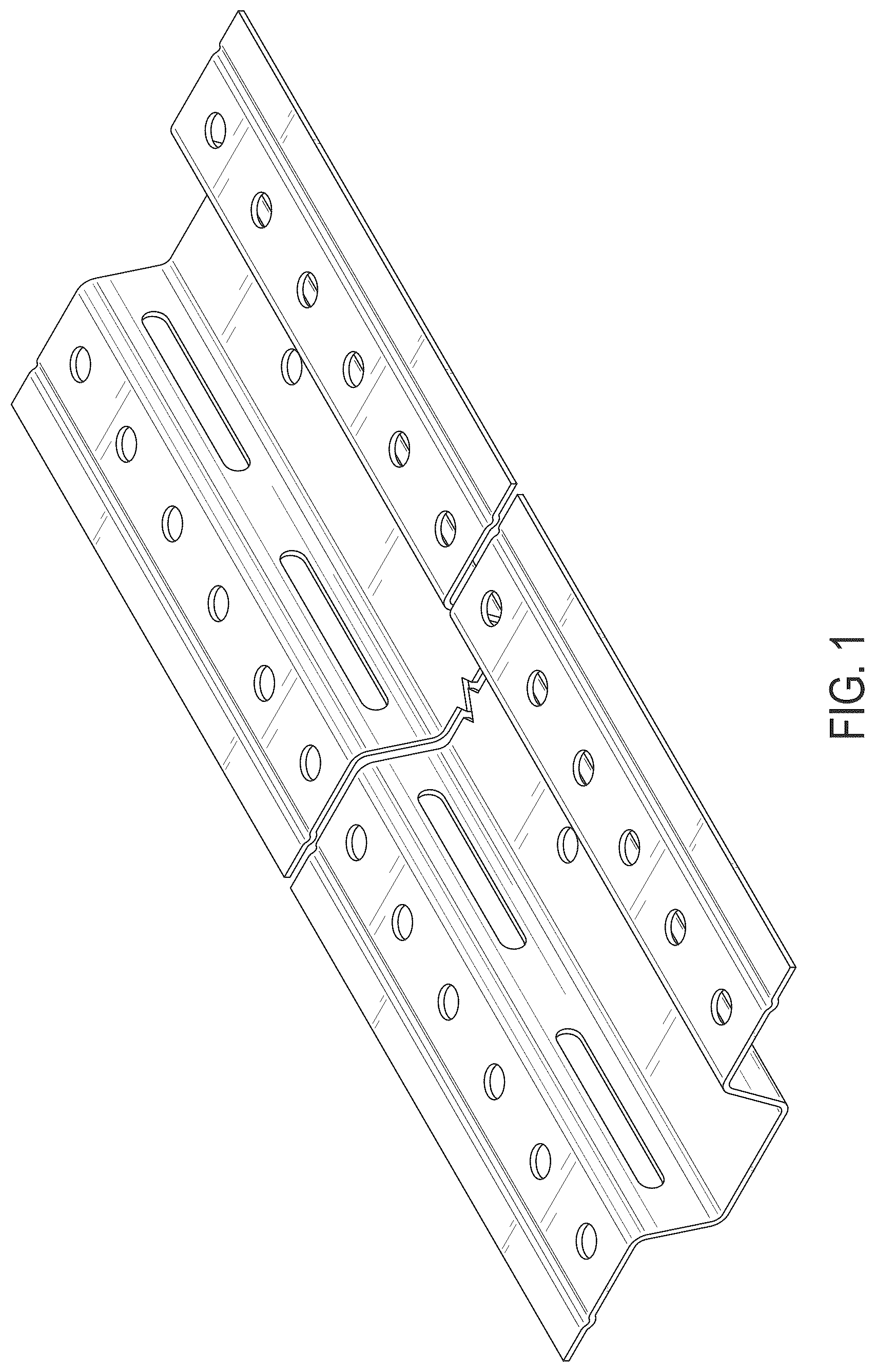
The ornamental design for a furring channel, as shown and described.
Full Description
Show full text →
is a backside perspective view of a furring channel showing an embodiment of the design;
is a rear plan view of the furring channel of ;
is a front plan view of the furring channel of ;
is an end elevation view of the furring channel of ;
is an end elevation view of the furring channel of opposite from the end shown in ;
is a side elevation view of the furring channel of ; and,
is a side elevation view of the furring channel of opposite from the side shown in .
In the drawings, , 6 and 7 show a symbolic break. Portions omitted between the break lines indicating indeterminate length form no part of the claimed design.
Figures (6)
Citations
This patent cites (13)
- USD245019
- USD537536
- USD543284
- USD767795
- US10060460
- USD929610
- US11885138
- USD1015497
- USD1025402
- US12000153
- US2013/0042571
- US2016/0273706
- US2023/0304281
Cited by (0)
- USD1117657: Screen Assembly for a Gutter Guard System
- USD1117658: Screen Assembly for a Gutter Guard System
- USD1107187: Screen Corner Assembly for a Gutter Guard System
- USD1107188: Screen Corner Assembly for a Gutter Guard System
- USD1107191: Screen Corner Assembly for a Gutter Guard System
- USD1107195: Screen Corner Assembly for a Gutter Guard System
- USD1106401: Screen Corner Assembly for a Gutter Guard System
- USD1097217: Connector for Elongated Ceiling Grid Members
- USD1091778: Gutter Guard
- USD1091779: Gutter Guard