Claims (1)
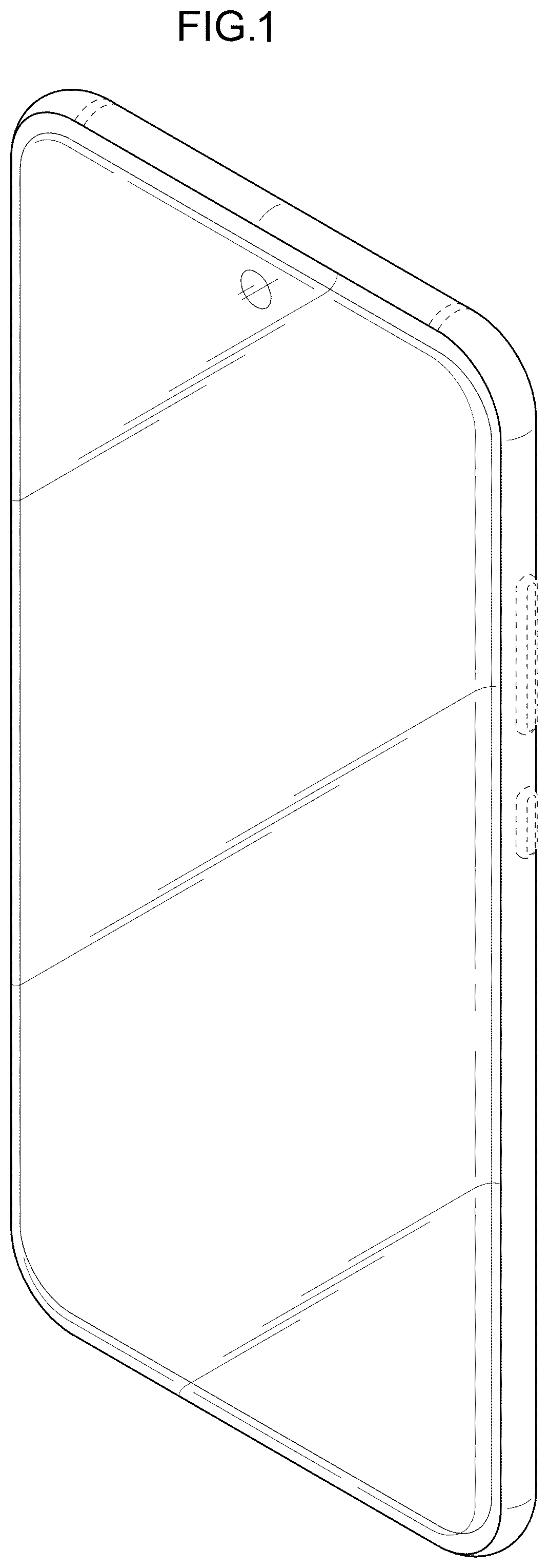
The ornamental design for an electronic device, as shown and described.
Full Description
Show full text →
is a front perspective view of a first embodiment of an electronic device showing my new design;
is a front view thereof;
is a rear view thereof;
is a left-side view thereof;
is a right-side view thereof;
is a top view thereof;
is a bottom view thereof;
is a rear perspective view thereof;
is a front perspective view of a second embodiment of an electronic device showing my new design;
is a front view thereof;
is a rear view thereof;
is a left-side view thereof;
is a right-side view thereof;
is a top view thereof;
is a bottom view thereof;
is a rear perspective view thereof;
is a front perspective view of a third embodiment of an electronic device showing my new design;
is a front view thereof;
is a rear view thereof;
is a left-side view thereof;
is a right-side view thereof;
is a top view thereof;
is a bottom view thereof;
is a rear perspective view thereof;
is a front perspective view of a fourth embodiment of an electronic device showing my new design;
is a front view thereof;
is a rear view thereof;
is a left-side view thereof;
is a right-side view thereof;
is a top view thereof;
is a bottom view thereof;
is a rear perspective view thereof;
is a front perspective view of a fifth embodiment of an electronic device showing my new design;
is a front view thereof;
is a rear view thereof;
is a left-side view thereof;
is a right-side view thereof;
is a top view thereof;
is a bottom view thereof;
is a rear perspective view thereof;
is a front perspective view of a sixth embodiment of an electronic device showing my new design;
is a front view thereof;
is a rear view thereof;
is a left-side view thereof;
is a right-side view thereof;
is a top view thereof;
is a bottom view thereof; and,
is a rear perspective view thereof.
The evenly-dashed broken lines in the drawings illustrate portions of the electronic device that form no part of the claimed design.
Figures (20)
Citations
This patent cites (112)
- USD613722
- USD654464
- USD665762
- USD695255
- USD722038
- USD723492
- USD746247
- USD756951
- USD765068
- USD783565
- USD784281
- USD788735
- USD796469
- USD800710
- USD802553
- USD816055
- USD822017
- USD825516
- USD828322
- USD829677
- USD830987
- USD837176
- USD840964
- USD846539
- USD848390
- USD849707
- USD849708
- USD852769
- USD856293
- USD856955
- USD858475
- USD859343
- USD859382
- USD859383
- USD861630
- USD863307
- USD863308
- USD864140
- USD866496
- USD876415
- USD879736
- USD886754
- USD890112
- USD890152
- USD890712
- USD891386
- USD894858
- USD894859
- USD896198
- USD897303
- USD897980
- USD897981
- USD900779
- USD901421
- USD903617
- USD903644
- USD904380
- USD908104
- USD910586
- USD911996
- USD911997
- USD911998
- USD911999
- USD912000
- USD912001
- USD912002
- USD912003
- USD916672
- USD916673
- USD916674
- USD916675
- USD916676
- USD916677
- USD919589
- USD922975
- USD922976
- USD924191
- USD929356
- USD929955
- USD931248
- USD933052
- USD940093
- USD941793
- USD950511
- USD951897
- USD954670
- USD958104
- USD958105
- USD959424
- USD960857
- USD961540
- USD962187
- USD962887
- USD963602
- USD965544
- USD965548
- USD966224
- USD966225
- USD967789
- USD973618
- USD976860
- USD978814
- USD978817
- USD978818
- USD978819
- USD981386
- USD981387
- US20110186345
- US20120175506
- US20180180866
- US20190293976
- US306236557