Abstract
A drive device includes a motor, a transmission, a housing, and a flow path. The transmission includes first to third shafts, and first to third bearings supporting the first to third shafts, respectively. The housing includes a side wall covering a gear chamber from one side in an axial direction, and having first to third bearing holding portions for holding the first to third bearings, respectively. The flow path includes a supply flow path portion that supplies a fluid to the inside of the second bearing holding portion, a first flow path portion that connects the inside of the second bearing holding portion and the inside of the first bearing holding portion, and a second flow path portion that connects the inside of the second bearing holding portion and the inside of the third bearing holding portion.
Claims (12)
1 . A drive device comprising: a motor; a transmission mechanism configured to transmit power of the motor; a housing provided with a gear chamber that accommodates the transmission mechanism; and a flow path at least a part of which is provided in the housing and through which a fluid can flow, wherein the transmission mechanism includes: a first shaft rotatable about a first axis extending in an axial direction; a second shaft rotatable about a second axis extending in parallel with the first axis; a third shaft rotatable about a third axis extending in parallel with the first axis and the second axis; a first bearing that supports the first shaft; a second bearing that supports the second shaft; and a third bearing that supports the third shaft, the housing includes: a side wall covering the gear chamber from one side in the axial direction; a first bearing holding portion that is provided in the side wall and holds the first bearing; a second bearing holding portion that is provided in the side wall and holds the second bearing; and a third bearing holding portion that is provided in the side wall and holds the third bearing, and the flow path includes: a supply flow path portion that supplies the fluid to an inside of the second bearing holding portion; a first flow path portion connecting the inside of the second bearing holding portion and an inside of the first bearing holding portion; and a second flow path portion connecting the inside of the second bearing holding portion and an inside of the third bearing holding portion.
Show 11 dependent claims
2 . The drive device according to claim 1 , wherein the second bearing holding portion includes: a facing surface positioned on one side in an axial direction with respect to an end portion on one side in the axial direction of the second shaft and extending in a direction orthogonal to the axial direction; and an inner side surface that extends in the axial direction and supports the second bearing from radially outside, and the inner side surface is provided with: a first opening that is an end portion of the first flow path portion; a second opening that is an end portion of the second flow path portion; and a wall that is positioned between the first opening and the second opening and protrudes radially inward.
3 . The drive device according to claim 2 , wherein the inner side surface is provided with a third opening that is an end portion of the supply flow path portion, a direction intersecting both an up-down direction and the axial direction is defined as a first direction, the first opening is positioned on one side in a first direction with respect to the wall, the second opening is positioned on an other side in the first direction with respect to the wall, and the third opening is positioned on one side in the first direction with respect to the wall.
4 . The drive device according to claim 3 , wherein the transmission mechanism includes a differential device including the third shaft.
5 . The drive device according to claim 2 , wherein the inner side surface is provided with a third opening that is an end portion of the supply flow path portion, a direction intersecting both an up-down direction and the axial direction is defined as a first direction, the first opening is positioned on one side in a first direction with respect to the wall, the second opening is positioned on an other side in the first direction with respect to the wall, and the third opening is positioned on the other side in the first direction with respect to the wall.
6 . The drive device according to claim 1 , wherein a cross-sectional area of the first flow path portion is larger than a cross-sectional area of the second flow path portion.
7 . The drive device according to claim 1 , wherein a cross-sectional area of the second flow path portion is larger than a cross-sectional area of the first flow path portion.
8 . The drive device according to claim 1 , wherein the second bearing holding portion has a facing surface located on one side in the axial direction with respect to the end portion on one side in the axial direction of the second shaft and extending in the direction orthogonal to the axial direction, the facing surface is provided with a recess recessed to one side in the axial direction, and the first flow path portion and the second flow path portion are connected to an inside of the recess.
9 . The drive device according to claim 8 , wherein the second bearing holding portion has an inner side surface extending in the axial direction and supporting the second bearing from a radially outer side, and the inner side surface is provided with: the first opening that is the end portion of the first flow path portion; the second opening that is the end portion of the second flow path portion; the wall that is positioned between the first opening and the second opening and protrudes radially inward, and the wall extends to an inside of the recess and is disposed on a side of the second opening with respect to a circumferential center of the recess.
10 . The drive device according to claim 8 , wherein the second bearing holding portion has an inner side surface extending from the facing surface to an other side in the axial direction and supporting the second bearing from a radially outer side, the inner side surface is provided with: the first opening that is the end portion of the first flow path portion; the second opening that is the end portion of the second flow path portion; and the wall that is positioned between the first opening and the second opening and protrudes radially inward, and the wall extends to the inside of the recess and is disposed on a side of the first opening with respect to a circumferential center of the recess.
11 . The drive device according to claim 1 , wherein the second bearing holding portion includes: a facing surface positioned on one side in the axial direction with respect to an end portion on one side in the axial direction of the second shaft and extending in a direction orthogonal to the axial direction; and an inner side surface that extends in the axial direction and supports the second bearing from radially outside, the inner side surface is provided with: a first opening that is an end portion of the first flow path portion; a second opening that is an end portion of the second flow path portion; and a third opening that is an end portion of the supply flow path portion, the facing surface is provided with a rib that protrudes to an other side in an axial direction and covers at least a part of the third opening, a direction intersecting both an up-down direction and an axial direction is defined as a first direction, the first opening and the second opening are positioned on one side in the first direction with respect to the second opening, and at least a part of the rib is provided on one side in the first direction with respect to the second opening.
12 . The drive device according to claim 11 , wherein the facing surface is provided with a recess recessed to one side in the axial direction, and the rib extends toward the recess.
Full Description
Show full text →
CROSS-REFERENCE TO RELATED APPLICATIONS
The present invention claims priority under 35 U.S.C. § 119 to Japanese Patent Application No. 2023-058151 filed on Mar. 31, 2023 and Japanese Patent Application No. 2024-013441 filed on Jan. 31, 2024, the entire contents of which are incorporated herein by reference.
FIELD OF THE INVENTION
The present invention relates to a drive device.
BACKGROUND
A drive device is mounted on a vehicle such as an electric vehicle and a hybrid vehicle. A fluid such as oil is stored in such a drive device, and the fluid lubricates gears and bearings in the drive device.
The bearing is held by a bearing holding portion provided in the housing. When a plurality of bearings are provided, it is required to stably supply fluid to each bearing and to suppress shortage of supply to some of the bearings.
SUMMARY
A drive device according to an embodiment of the present invention includes a motor, a transmission mechanism configured to transmit power of the motor, a housing provided with a gear chamber that accommodates the transmission mechanism, and a flow path at least a part of which is provided in the housing and through which a fluid can flow. The transmission mechanism includes a first shaft rotatable about a first axis extending in an axial direction, a second shaft rotatable about a second axis extending in parallel with the first axis, a third shaft rotatable about a third axis extending in parallel with the first axis and the second axis, a first bearing that supports the first shaft, a second bearing that supports the second shaft, and a third bearing that supports the third shaft. The housing includes a side wall covering the gear chamber from one side in an axial direction, and a first bearing holding portion that is provided on the side wall and holds the first bearing. A second bearing holding portion that is provided on the side wall and holds the second bearing is provided. A third bearing holding portion that is provided on the side wall and holds the third bearing is provided. The flow path includes a supply flow path portion that supplies a fluid to the inside of the second bearing holding portion, a first flow path portion that connects the inside of the second bearing holding portion and the inside of the first bearing holding portion, and a second flow path portion that connects the inside of the second bearing holding portion and the inside of the third bearing holding portion.
The above and other elements, features, steps, characteristics and advantages of the present disclosure will become more apparent from the following detailed description of the preferred embodiments with reference to the attached drawings.
BRIEF DESCRIPTION OF THE DRAWINGS
is a conceptual diagram of a drive device of an embodiment;
is a front view of a side wall according to a drive device of an embodiment;
is a front view of a second bearing holding portion according to an embodiment;
is a schematic cross-sectional view of the second bearing holding portion taken along line IV-IV in ;
is a schematic view of a second bearing holding portion according to a first modification;
is a schematic view of a second bearing holding portion according to a second modification;
is a schematic view of a second bearing holding portion according to a third modification;
is a schematic view of a second bearing holding portion according to a fourth modification;
is a schematic view of a second bearing holding portion according to a fifth modification;
is a schematic view of a second bearing holding portion of a sixth modification;
is a schematic view of a second bearing holding portion of a seventh modification; and
is a schematic cross-sectional view of the second bearing holding portion taken along line XII-XII in .
DETAILED DESCRIPTION
A drive device according to an embodiment of the present invention will be described below with reference to the drawings. In description below, an up-down direction is defined based on a positional relationship when a drive device 1 of the present embodiment is mounted on a vehicle (not illustrated) positioned on a horizontal road surface.
In the drawings, an XYZ coordinate system is illustrated appropriately as a three-dimensional orthogonal coordinate system. In the XYZ coordinate system, a Z-axis direction corresponds to the up-down direction. The up-down direction is, for example, a vertical direction. A +Z side corresponds to an upper side in the vertical direction, while a −Z side corresponds to a lower side in the vertical direction. In the present embodiment, the upper side in the vertical direction will be referred to simply as the “upper side” and the lower side in the vertical direction will be simply referred to as the “lower side”. An X-axis direction is a direction orthogonal to the Z-axis direction and is a vehicle front-rear direction on which the drive device 1 is mounted. In the present embodiment, a +X side is a front side of the vehicle, and a-X side is a rear side of the vehicle. A Y-axis direction corresponds to a left-right direction of the vehicle, i.e., a width direction of the vehicle, and is a direction perpendicular to both the X-axis direction and the Z-axis direction. The Y-axis direction corresponds to the axial directions of a first axis J 1 , a second axis J 2 , and a third axis J 3 , which will be described later. Each of the front-rear direction and the left-right direction is a horizontal direction perpendicular to the vertical direction.
The first axis J 1 , the second axis J 2 , and the third axis J 3 , which are appropriately shown in each figure, are parallel to each other and extend in the Y-axis direction (that is, the left-right direction of the vehicle and the direction along the horizontal plane). In the present specification, unless otherwise specified, a direction parallel to the axes J 1 , J 2 , and J 3 is simply referred to as an “axial direction”, a radial direction with the axis J 1 as a center is simply referred to as a “radial direction”, and a circumferential direction with the axis J 1 as a center, that is, around the axis J 1 is simply referred to as a “circumferential direction”. “Extending in the axial direction” means extending in a direction in which the first axis J 1 , the second axis J 2 , and the third axis J 3 extend. In the following description, one side in the axial direction means a +Y side in the direction along the Y axis, and the other side in the axial direction means a-Y side in the direction along the Y axis. Note that, in the present embodiment, the “parallel direction” also includes a substantially parallel direction, and the “perpendicular direction” also includes a substantially perpendicular direction. In addition, in the present specification, “facing the axial direction” means facing a direction parallel to the axial direction or a direction having an axial component.
In the following description, a vehicle front-rear direction which is a direction parallel to the X axis is simply referred to as a “first direction”. The front side (+X side) of the vehicle is simply referred to as one side in the first direction, and the rear side (−X side) of the vehicle is simply referred to as the other side in the first direction. The first direction is a direction intersecting both the up-down direction and the axial direction.
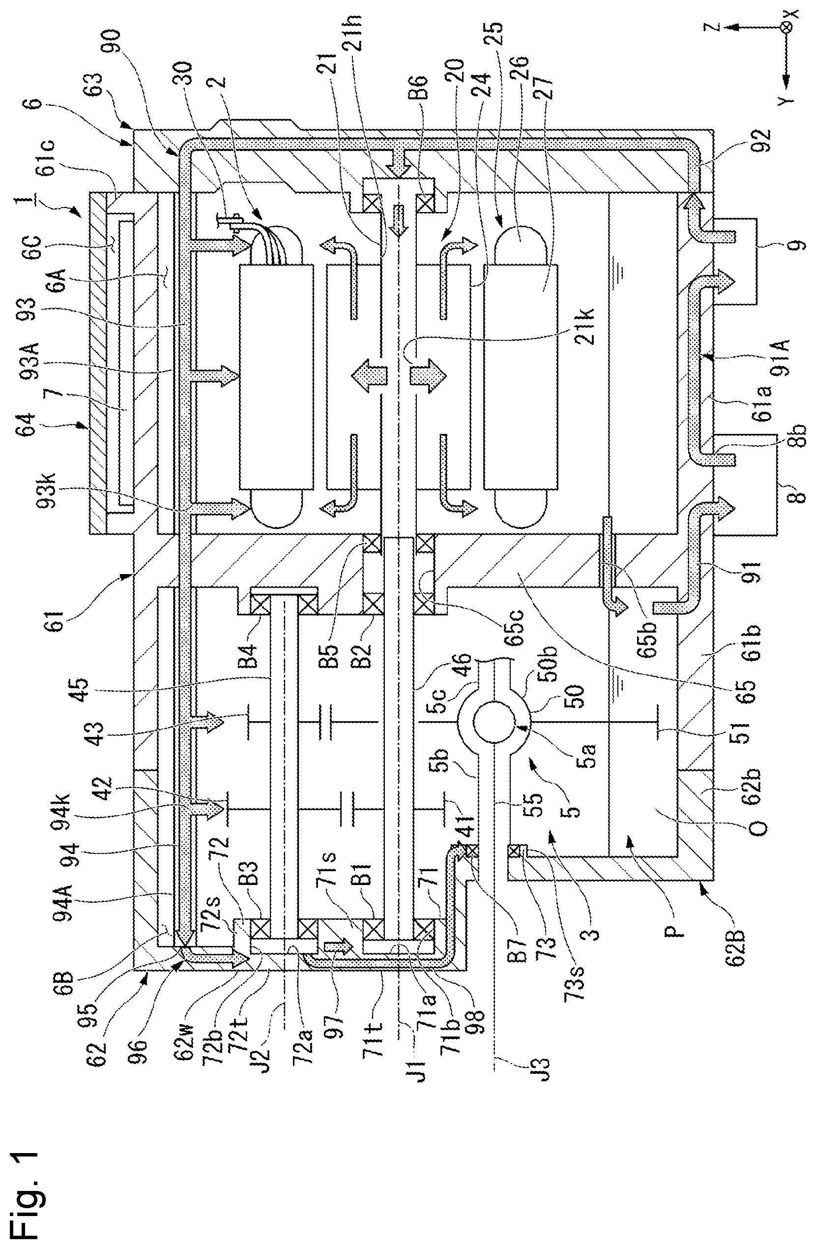
is a conceptual diagram of the drive device 1 according to the embodiment.
The drive device 1 of the present embodiment is mounted on an electric vehicle (EV) and is used as a power source thereof. Note that, the drive device 1 may be mounted on a vehicle including a motor as a power source, such as a hybrid electric car (HEV) or a plug-in hybrid electric car (PHV).
As illustrated in , the drive device 1 includes a motor 2 , a transmission mechanism 3 , an inverter 7 , a housing 6 , a fluid O, a pump 8 , and a cooler 9 . The motor 2 , the transmission mechanism 3 , and the inverter 7 are accommodated in the housing 6 . The fluid O is stored in the housing 6 . The pump 8 and the cooler 9 are fixed to the outer side surface of the housing 6 .
The motor 2 of the present embodiment is a three-phase AC motor. The motor 2 has both a function as an electric motor and a function as a generator. The motor 2 is located on the other side (−Y side) of the transmission mechanism 3 in the axial direction. The motor 2 includes a rotor 20 arranged to rotate about the first axis (motor axis) J 1 , which extends in a horizontal direction, and a stator 25 arranged radially outside of the rotor 20 . The motor 2 of the present embodiment is an inner rotor type motor in which the rotor 20 is arranged inside the stator 25 . The configuration of the motor 2 is not limited to the present embodiment.
The rotor 20 rotates about the first axis J 1 extending in the horizontal direction. The rotor 20 includes a motor shaft 21 , a rotor core 24 fixed to an outer peripheral surface of the motor shaft 21 , and a rotor magnet (not illustrated) fixed to the rotor core.
The motor shaft 21 extends along the axial direction about the first axis J 1 . The motor shaft 21 rotates about the first axis J 1 . A first shaft 46 of the transmission mechanism 3 is connected to an end portion of the motor shaft 21 on one side (+Y side) in the axial direction. As a result, a torque of the rotor 20 is transmitted to the transmission mechanism 3 . The motor shaft 21 is a hollow shaft. The motor shaft 21 is provided with a hole 21 k extending radially outside from a hollow portion 21 h . The motor shaft 21 is rotatably supported by the housing 6 via bearings B 5 and B 6 .
The stator 25 is held by the housing 6 . The stator 25 surrounds the rotor 20 from the radially outer side. The stator 25 includes a stator core 27 having a substantially annular shape centered on the first axis J 1 and a coil 26 attached to the stator core 27 . The stator core 27 is fixed to the housing 6 .
The coil 26 is attached to each tooth portion of the stator core 27 with an insulator (not illustrated) therebetween. The coil 26 includes a plurality of coil wires. In addition, the coil 26 may be configured by connecting a plurality of rod-shaped conductors. A bus bar 30 is connected to the coil 26 . An alternating current is supplied to the coil 26 via the bus bar 30 .
The inverter 7 converts direct current supplied from a battery (not illustrated) into alternating current. The inverter 7 is connected to the coil 26 of the stator 25 via the bus bar 30 . The inverter 7 supplies power to the motor 2 via the bus bar 30 to control the motor 2 .
The transmission mechanism 3 is located on one side (−Y side) of the motor 2 in the axial direction. The transmission mechanism 3 transmits power of the motor 2 to output the power from an output shaft 55 . The transmission mechanism 3 includes a first shaft 46 , a first gear 41 , a second shaft 45 , a second gear 42 , a third gear 43 , a differential device 5 , an output shaft 55 , and a plurality of bearings B 1 , B 2 , B 3 , B 4 , and B 7 .
The first shaft 46 and the first gear 41 are disposed around the first axis J 1 . The first shaft 46 and the first gear 41 are rotatable about the first axis J 1 . The first shaft 46 extends in the axial direction of the first axis J 1 . The end portion on the other side (−Y side) in the axial direction of the motor shaft 21 is connected to the first shaft 46 . The first shaft 46 rotates in synchronization with the motor shaft 21 . The first gear 41 is provided on an outer peripheral surface of the first shaft 46 . The first gear 41 rotates about the first axis J 1 together with the first shaft 46 . The first shaft 46 is rotatably supported by the housing 6 via the bearings B 1 and B 2 .
The second shaft 45 , the second gear 42 , and the third gear 43 are disposed about the second axis J 2 extending in parallel with the first axis J 1 . The second shaft 45 , the second gear 42 , and the third gear 43 are rotatable about the second axis J 2 . The second shaft 45 extends along the axial direction of the second axis J 2 . The second shaft 45 is rotatably supported by the housing 6 the via bearings B 3 and B 4 . The second gear 42 and the third gear 43 are provided on the outer peripheral surface of the second shaft 45 . The second gear 42 and the third gear 43 are disposed at intervals in the axial direction. The second gear 42 and the third gear 43 rotate around the second axis J 2 together with the second shaft 45 . The second gear 42 meshes with the first gear 41 . The third gear 43 meshes with a ring gear 51 of the differential device 5 described below.
The differential device 5 includes a ring gear 51 , a differential case 50 , and a differential mechanism 5 a . The differential device 5 is disposed about the third axis J 3 extending in parallel with the first axis J 1 and the second axis J 2 . The differential device 5 is rotatable about the third axis J 3 . The ring gear 51 meshes with the third gear 43 . The ring gear 51 rotates about the third axis J 3 . The ring gear 51 is fixed to the differential case 50 .
The differential case 50 includes a case portion 50 b that accommodates the differential mechanism 5 a therein, and a third shaft 5 b and a fourth shaft 5 c . The third shaft 5 b protrudes from the outer side surface of the case portion 50 b to one side (+Y side) in the axial direction. The fourth shaft 5 c protrudes from the outer side surface of the case portion 50 b to the other side (−Y side) in the axial direction. The third shaft 5 b and the fourth shaft 5 c have a cylindrical shape extending along the axial direction about the third axis J 3 . The output shaft 55 is disposed inside each of the third shaft 5 b and the fourth shaft 5 c . The third shaft 5 b and the fourth shaft 5 c rotate together with the ring gear 51 about the third axis J 3 . The third shaft 5 b is rotatably supported by the housing 6 via the bearing B 7 . The fourth shaft 5 c is rotatably supported by the housing 6 via a bearing (not illustrated). That is, the transmission mechanism 3 includes the third shaft 5 b and the fourth shaft 5 c that are rotatable about the third axis J 3 . The differential device 5 includes a third shaft 5 b and a fourth shaft 5 c.
The differential mechanism 5 a is disposed inside the differential case 50 . The rotation of the ring gear 51 is transmitted to the differential mechanism 5 a via the differential case 50 . A pair of output shafts 55 is connected to the differential mechanism 5 a . The differential mechanism 5 a transfers the torque to the output shafts 55 of the left and right wheels while absorbing a difference in speed between the left and right wheels when the vehicle turns.
The pair of output shafts 55 extends from the differential mechanism 5 a to one side and the other side in the axial direction about the third axis J 3 . The pair of output shafts 55 is rotatably supported by the housing 6 about the third axis J 3 via bearings (not illustrated) arranged on the inner peripheral surface of the third shaft 5 b or the fourth shaft 5 c . A wheel (not illustrated) is connected to each of the pair of output shafts 55 .
The torque output from the motor 2 is transmitted to the ring gear 51 of the differential device 5 via the motor shaft 21 , the first shaft 46 , the first gear 41 , the second gear 42 , the second shaft 45 and the third gear 43 , and further, is transmitted to the wheel via the differential mechanism 5 a , and the output shaft 55 . In this manner, the transmission mechanism 3 transmits the torque of the motor 2 to the wheels of the vehicle.
The plurality of bearings B 1 , B 2 , B 3 , B 4 , B 5 , B 6 , and B 7 are held by the housing 6 . The bearings B 1 and B 2 are arranged around the first axis J 1 . The bearing B 1 supports the end portion of the first shaft 46 on one side (+Y side) in the axial direction, and the bearing B 2 supports the end portion of the first shaft 46 on the other side (−Y side) in the axial direction. The bearings B 3 and B 4 are disposed around the second axis J 2 . The bearing B 3 supports the end portion of the second shaft 45 on one side (+Y side) in the axial direction, and the bearing B 4 supports the end portion of the second shaft 45 on the other side (−Y side) in the axial direction. The bearings B 5 and B 6 are disposed around the first axis J 1 . The bearing B 5 supports the end portion of the motor shaft 21 on one side (+Y side) in the axial direction, and the bearing B 6 supports the end portion of the motor shaft 21 on the other side (−Y side) in the axial direction. The bearing B 7 is disposed about the third axis J 3 . The bearing B 7 supports the end portion of the third shaft 5 b on one side (+Y side) in the axial direction. In the description of the present embodiment, the bearing B 1 is referred to as a first bearing, the bearing B 3 is referred to as a second bearing, and the bearing B 7 is referred to as a third bearing.
The housing 6 is provided with a motor chamber 6 A that accommodates the motor 2 , a gear chamber 6 B that accommodates the transmission mechanism 3 , and an inverter chamber 6 C that accommodates the inverter 7 . The gear chamber 6 B is located on one side (+Y side) of the motor chamber 6 A in the axial direction. The inverter chamber 6 C is located on the upper side (+Z side) of the motor chamber 6 A.
The fluid O is stored in the housing 6 . The housing 6 is provided with a flow path 90 through which the fluid O flows. That is, the drive device 1 includes the flow path 90 through which the fluid O can flow. The fluid O passes through the flow path 90 and circulates in the housing 6 . The fluid O serves as a cooling refrigerant for the motor 2 and a lubricating oil for the transmission mechanism 3 . An oil equivalent to a lubricating oil (ATF: Automatic Transmission Fluid) for an automatic transmission having a relatively low viscosity is preferably used as the fluid O in order to perform functions of a lubricating oil and a cooling oil.
The fluid O is accumulated in a lower region inside the housing 6 . That is, the fluid O accumulates in the lower region in the housing 6 . Hereinafter, the lower region in the housing 6 where the fluid O is stored is referred to as a reservoir P. In the housing 6 of the present embodiment, the bottom surface of the motor chamber 6 A and the bottom surface of the gear chamber 6 B are substantially aligned in the up-down direction. Therefore, the reservoir P is provided across the lower region of the motor chamber 6 A and the lower region of the housing 6 .
The ring gear 51 is immersed in the fluid O in the reservoir P. The ring gear 51 lifts up the fluid O in the reservoir P and scatters the fluid O into the gear chamber 6 B as the ring gear rotates about the third axis J 3 . The fluid O scraped up by the ring gear 51 is supplied to each gear in the gear chamber 6 B and used for lubrication of a tooth surface or the like of the gear.
The fluid O in the reservoir P passes through the flow path 90 and is sent to the upper region of the motor chamber 6 A and the upper region of the gear chamber 6 B. The fluid O sent to the upper region of the motor chamber 6 A drops into the reservoir P in the lower region of the motor chamber 6 A after cooling the motor 2 along the surface of the motor 2 . The fluid O sent to the upper region of the gear chamber 6 B lubricates each gear of the transmission mechanism 3 and a bearing supporting the transmission mechanism 3 , and then returns to the reservoir P in the lower region of the gear chamber 6 B.
The housing 6 is configured by combining a plurality of members. The housing 6 includes a housing body (first member) 61 , a motor cover 63 located on the other side (−Y side) in the axial direction of the housing body 61 , a gear cover (second member) 62 located on one side (+Y side) in the axial direction of the housing body 61 , and an inverter cover 64 located on the upper side (+Z side) of the housing body 61 .
The housing body 61 includes a partition wall 65 , a first cylindrical portion 61 a , a second cylindrical portion 61 b , and a box-shaped portion 61 c . The partition wall 65 extends along a plane orthogonal to the first axis J 1 . The first cylindrical portion 61 a protrudes from the partition wall 65 to the other side (−Y side) in the axial direction. The first cylindrical portion 61 a has a cylindrical shape surrounding the first axis J 1 . The second cylindrical portion 61 b protrudes from the partition wall 65 to one side (+Y side) in the axial direction. The second cylindrical portion 61 b has a cylindrical shape surrounding the first axis J 1 , the second axis J 2 , and the third axis J 3 . The box-shaped portion 61 c has a box shape that is open upward with a part of the outer side surface of the first cylindrical portion 61 a as a bottom surface. The opening of the box-shaped portion 61 c is covered by the inverter cover 64 . The inverter chamber 6 C is provided in a space surrounded by the inner side surface of the box-shaped portion 61 c and the inverter cover 64 .
The partition wall 65 partitions the motor chamber 6 A and the gear chamber 6 B. The partition wall 65 is provided with a shaft insertion hole 65 c and a partition wall opening 65 b . The shaft insertion hole 65 c and the partition wall opening 65 b pass through the partition wall 65 in the axial direction. The shaft insertion hole 65 c and the partition wall opening 65 b connect the motor chamber 6 A and the gear chamber 6 B, and allow them to communicate with each other. The inner side surface of the shaft insertion hole 65 c supports the motor shaft 21 and the first shaft 46 via bearings B 5 and B 2 . In the present embodiment, the motor shaft 21 and the first shaft 46 are connected to each other inside the shaft insertion hole 65 c . However, the motor shaft 21 and the first shaft 46 may be connected to each other outside the shaft insertion hole 65 c . The partition wall opening 65 b is positioned below the shaft insertion hole 65 c . The partition wall opening 65 b constitutes a flow path of the fluid O flowing from the motor chamber 6 A to the gear chamber 6 B.
The motor cover 63 has a plate shape extends along a plane orthogonal to the first axis J 1 . The motor cover 63 covers the opening on the other side (−Y side) in the axial direction of the first cylindrical portion 61 a . The motor chamber 6 A is provided in a space radially inside the first cylindrical portion 61 a , on the other side (−Y side) in the axial direction of the partition wall 65 , and on one side (+Y side) in the axial direction of the motor cover 63 .
The gear cover 62 has a concave shape that is open to the other side (−Y side) in the axial direction. The gear cover 62 includes a plate-shaped side wall 62 w extending along a plane orthogonal to the first axis J 1 and a third cylindrical portion 62 b protruding from the side wall 62 w to the other side (−Y side) in the axial direction. The gear cover 62 covers an opening on one side (+Y side) in the axial direction of the second cylindrical portion 61 b . An end surface on the other side (−Y side) in the axial direction of the third cylindrical portion 62 b is connected to an end surface on one side (+Y side) in the axial direction of the second cylindrical portion 61 b . The gear chamber 6 B is provided in a space radially inside the second cylindrical portion 61 b and the third cylindrical portion 62 b , on one side (+Y side) in the axial direction of the partition wall 65 , and on the other side (−Y side) in the axial direction of the side wall 62 w . That is, the side wall 62 w covers the gear chamber 6 B from one side (+Y side) in the axial direction.
is a front view of the side wall 62 w according to the drive device 1 of the present embodiment.
The side wall 62 w is provided with a first bearing holding portion 71 , a second bearing holding portion 72 , and a third bearing holding portion 73 . That is, the housing 6 includes the first bearing holding portion 71 , the second bearing holding portion 72 , and the third bearing holding portion 73 . The first bearing holding portion 71 holds the first bearing B 1 . The second bearing holding portion 72 holds the second bearing B 3 . The third bearing holding portion 73 holds the third bearing B 7 .
is a front view of the second bearing holding portion 72 . is a schematic cross-sectional view of the second bearing holding portion 72 taken along line IV-IV in .
As illustrated in , the second bearing holding portion 72 includes a second cylindrical portion (second wall) 72 s and a second facing wall 72 t . The second cylindrical portion 72 s has a cylindrical shape centered on the second axis J 2 . The second cylindrical portion 72 s surrounds the second bearing B 3 from the radially outer side of the second axis J 2 . The second facing wall 72 t extends along a plane orthogonal to the second axis J 2 . The second facing wall 72 t is a part of the side wall 62 w , and is a region surrounded by the second cylindrical portion 72 s when viewed from the axial direction.
The second facing wall 72 t has a second facing surface (facing surface) 72 a facing the other side (−Y side) in the axial direction. That is, the second bearing holding portion 72 has the second facing surface 72 a . The second facing surface 72 a extends in a direction orthogonal to the axial direction. The second facing surface 72 a is located on one side in the axial direction with respect to the end portion on one side (+Y side) in the axial direction of the second shaft 45 . The second facing surface 72 a faces an end surface 45 f on one side in the axial direction of the second shaft 45 in the axial direction.
The second cylindrical portion 72 s has a second inner side surface (inner side surface) 72 b . That is, the second bearing holding portion 72 has the second inner side surface 72 b . The second inner side surface 72 b includes a stepped surface 72 f facing the other side (−Y side) in the axial direction, a large diameter portion 72 g located on the other side in the axial direction with respect to the stepped surface 72 f , and a small diameter portion 72 h located on one side in the axial direction with respect to the stepped surface 72 f.
The stepped surface 72 f has a substantially annular shape when viewed from the axial direction. A recessed groove 72 i is provided on the outer edge of the stepped surface 72 f . The recessed groove 72 i is recessed from the surface on the other side in the axial direction of the stepped surface 72 f to the one side in the axial direction. The recessed groove 72 i extends in the circumferential direction when viewed from the axial direction. The stepped surface 72 f supports the second bearing B 3 from one side (+Y side) in the axial direction. A shim S having a substantially annular plate shape is disposed between the stepped surface 72 f and the second bearing B 3 in the axial direction.
The large diameter portion 72 g is a cylindrical radially inner side surface extending in the axial direction with the second axis J 2 as the center. The large diameter portion 72 g extends from the outer edge of the stepped surface 72 f to the other side (−Y side) in the axial direction. As described above, since the recessed groove 72 i is provided in the outer edge of the stepped surface 72 f of the present embodiment, the large diameter portion 72 g is connected to the inner side surface of the recessed groove 72 i . The large diameter portion 72 g surrounds the outer side surface of the second bearing B 3 from the radially outer side. The second inner side surface 72 b supports the second bearing B 3 in the large diameter portion 72 g from the radially outer side about the second axis J 2 .
The small diameter portion 72 h extends from the inner edge of the stepped surface 72 f to one side (+Y side) in the axial direction. The small diameter portion 72 h is connected to the second facing surface 72 a . That is, the second inner side surface 72 b extends from the second facing surface 72 a to the other side (−Y side) in the axial direction in the small diameter portion 72 h . The small diameter portion 72 h is a cylindrical radially inner side surface extending in the axial direction with the second axis J 2 as the center. The small diameter portion 72 h has a smaller inner diameter than the large diameter portion 72 g.
As illustrated in , the second inner side surface 72 b is provided with a first concave portion 72 j , a second concave portion 72 k , and a third concave portion 72 m . The first concave portion 72 j and the second concave portion 72 k are recessed radially outside from the small diameter portion 72 h . The stepped surface 72 f and the small diameter portion 72 h are disconnected at the first concave portion 72 j and the second concave portion 72 k . The first concave portion 72 j is disposed immediately below the second axis J 2 . The second concave portion 72 k is disposed above the second axis J 2 .
In the present specification, “arranged immediately below” means arranged on the lower side and overlapping when viewed from the up-down direction.
The third concave portion 72 m is recessed radially outside from the large diameter portion 72 g . The third concave portion 72 m is disposed radially outside the first concave portion 72 j . The circumferential position of the third concave portion 72 m overlaps the circumferential position of the first concave portion 72 j . The third concave portion 72 m overlaps a second opening 98 a described later when viewed from the axial direction. As illustrated in , the bottom surface of the third concave portion 72 m faces the outer peripheral surface of the second bearing B 3 with a gap interposed therebetween. For example, when the fluid O is excessively supplied into the second bearing holding portion 72 , the fluid O passes through the third concave portion 72 m and flows out from the second bearing holding portion 72 .
As illustrated in , the second facing surface 72 a is provided with a recess 77 recessed to one side (+Y side) in the axial direction. In the present embodiment, the recess 77 is located immediately below the second axis J 2 . However, at least a part of the recess 77 may be located above the second axis J 2 . The recess 77 is disposed along the circumferential direction in a part of the large diameter portion 72 g . The recess 77 is disposed inside the first concave portion 72 j of the second inner side surface 72 b . That is, the first concave portion 72 j overlaps the recess 77 to be described later when viewed from the axial direction.
As illustrated in , the recess 77 has a side wall surface 77 a , a bottom wall surface 77 b , and an inclined surface 77 c . The bottom wall surface 77 b is a surface facing the other side (−Y side) in the axial direction. The bottom wall surface 77 b extends along a plane orthogonal to the axial direction.
The side wall surface 77 a is a surface facing radially inward. The side wall surface 77 a extends from the bottom wall surface 77 b to the other side (−Y side) in the axial direction. The side wall surface 77 a extends in a substantially arc shape when viewed from the axial direction. The side wall surface 77 a is connected to the small diameter portion 72 h of the second inner side surface 72 b . The side wall surface 77 a can be regarded as a part of the second inner side surface 72 b.
As illustrated in , the inclined surface 77 c extends to both sides in the first direction (X-axis direction) on the upper side of the bottom wall surface 77 b when viewed in the axial direction. That is, the inclined surface 77 c surrounds the bottom wall surface 77 b from three directions when viewed from the axial direction. As illustrated in , the inclined surface 77 c is connected to the bottom wall surface 77 b . In the direction orthogonal to the axial direction, the dimension between the inclined surface 77 c and the bottom wall surface 77 b gradually increases toward the other side (−Y side) in the axial direction.
A wall 76 is provided on the second inner side surface 72 b . The wall 76 protrudes radially inward from the small diameter portion 72 h of the second inner side surface 72 b . The wall 76 overlaps the recess 77 when viewed from the axial direction. As illustrated in , the wall 76 extends along the axial direction. The wall 76 extends to the inside of the recess 77 . That is, a portion on one side in the axial direction of the wall 76 protrudes radially inward from the side wall surface 77 a of the recess 77 . The wall 76 is connected to the bottom wall surface 77 b of the recess 77 .
As illustrated in , the first bearing holding portion 71 includes a first cylindrical portion (first wall) 71 s and a first facing wall 71 t . The first cylindrical portion 71 s has a substantially cylindrical shape centered on the first axis J 1 . The first cylindrical portion 71 s surrounds the first bearing B 1 from the radially outer side of the first axis J 1 . As illustrated in , the first cylindrical portion 71 s has a first inner side surface 71 b . The first inner side surface 71 b supports the first bearing B 1 from the radial outside about the first axis J 1 . Although not illustrated, the first cylindrical portion 71 s has substantially the same configuration as the second cylindrical portion 72 s described above. That is, the first inner side surface 71 b is provided with a stepped portion, a large diameter portion, and a small diameter portion similar to those of the second inner side surface 72 b . The first facing wall 71 t extends along a plane orthogonal to the first axis J 1 . The first facing wall 71 t is a part of the side wall 62 w , and is a region surrounded by the first cylindrical portion 71 s when viewed from the axial direction. The first facing wall 71 t has a first facing surface 71 a facing the other side (−Y side) in the axial direction. The first facing surface 71 a extends in a direction orthogonal to the axial direction. The first facing surface 71 a is located on one side in the axial direction with respect to an end portion on one side (+Y side) in the axial direction of the first shaft 46 . The first facing surface 71 a faces the end surface on one side in the axial direction of the first shaft 46 in the axial direction. The first facing surface 71 a is connected to the first inner side surface 71 b . That is, the first inner side surface 71 b extends from the first facing surface 71 a to the other side (−Y side) in the axial direction.
As illustrated in , the third bearing holding portion 73 has a third cylindrical portion (third wall) 73 s . The third cylindrical portion 73 s has a substantially cylindrical shape centered on the third axis J 3 . The third cylindrical portion 73 s surrounds the third bearing B 7 from the radially outer side of the third axis J 3 . The third cylindrical portion 73 s extends from the side wall 62 w to the other side (−Y side) in the axial direction. The third cylindrical portion 73 s has a third inner side surface 73 b . The third inner side surface 73 b supports the third bearing B 7 from the radial outside about the third axis J 3 . Although not illustrated, the third cylindrical portion 73 s has substantially the same configuration as the second cylindrical portion 72 s described above. That is, the third inner side surface 73 b is provided with a stepped portion, a large diameter portion, and a small diameter portion similar to those of the second inner side surface 72 b.
As illustrated in , the gear chamber 6 B is provided with a guide wall 67 extending in a curved manner along the tooth tip of the ring gear 51 . In the present embodiment, the guide wall 67 is a rib protruding from the side wall 62 w to the other side (−Y side) in the axial direction. The guide wall 67 extends in a substantially arc shape about the third axis J 3 . The guide wall 67 is curved along the tooth tip of the ring gear 51 . The guide wall 67 guides the fluid O in the reservoir P in the circumferential direction around the third axis J 3 along the tooth tip of the ring gear 51 by the surface facing the radial inside of the third axis J 3 . The fluid O is efficiently scraped up by the ring gear 51 by providing the guide wall 67 . Note that the guide wall 67 may be a member separate from the side wall 62 w . The partition wall 65 may be provided as a rib protruding to one side in the axial direction. The guide wall 67 may be configured by combining a rib provided on the side wall 62 w and protruding to the other side (−Y side) in the axial direction and a rib provided on the partition wall 65 and protruding to one side (+Y side) in the axial direction.
The flow path 90 illustrated in is a circulation path through which the fluid O flows. That is, the fluid O flows through the flow path 90 provided in the housing 6 . At least a part of the flow path 90 may be provided in the housing 6 . The flow path 90 is a path of the fluid O that is fed to the fluid O from the fluid reservoir P to the motor 2 and the transmission mechanism 3 . In the present specification, the concept of the “flow path” is not only a path that constantly generates a flow of the fluid O directed in one direction, but also a path that temporarily retains the fluid O and a path in which the fluid O drips.
The pump 8 , the cooler 9 , the first supply pipe 93 A, and the second supply pipe 94 A are disposed in the flow path 90 . The first supply pipe 93 A and the second supply pipe 94 A are disposed inside the housing 6 .
The pump 8 sucks and pressure-feeds the fluid O from the reservoir P of the gear chamber 6 B. The pump 8 supplies the fluid O to the motor 2 and the transmission mechanism 3 . In the present embodiment, the pump 8 is an electric pump driven by electricity.
The cooler 9 cools the fluid O in the flow path 90 . A refrigerant (not illustrated) flows inside the oil cooler 9 . The cooler 9 is a heat exchanger that transfers the heat of fluid O to the refrigerant. The fluid O pumped from the pump 8 flows into the cooler 9 . The flowed fluid O is cooled by heat exchange with the refrigerant in the cooler 9 . The refrigerant is separately cooled by a radiator (not illustrated).
The first supply pipe 93 A is disposed in the motor chamber 6 A. In the present embodiment, two first supply pipes 93 A are provided. The two first supply pipes 93 A extend along the axial direction on the radially outer side of the stator 25 . The end portion on one side (+Y side) in the axial direction of the first supply pipe 93 A is supported by the partition wall 65 , and the end portion on the other side (−Y side) in the axial direction is supported by the motor cover 63 . The first supply pipe 93 A is provided with a plurality of ejection holes 93 k opened toward the stator 25 . The number of first supply pipes 93 A is not limited to two. For example, one first supply pipe 93 A may be provided, or three or more first supply pipes may be provided.
The second supply pipe 94 A is disposed in the gear chamber 6 B. The second supply pipe 94 A extends along the axial direction. The end portion on one side (+Y side) in the axial direction of the second supply pipe 94 A is supported by the gear cover 62 , and the end portion on the other side (−Y side) in the axial direction is supported by the partition wall 65 . The second supply pipe 94 A of the present embodiment is arranged side by side with the first supply pipe 93 A in the axial direction. The second supply pipe 94 A is provided with a plurality of ejection holes 94 k opened toward the transmission mechanism 3 . The first supply pipe 93 A and the second supply pipe 94 A may not be arranged side by side in the axial direction.
The flow path 90 of the present embodiment includes a suction flow path portion 91 , a first pressure feed flow path portion 91 A, a second pressure feed flow path portion 92 , a third pressure feed flow path portion 93 , a fourth pressure feed flow path portion 94 , a feed portion 95 , a supply flow path portion 96 , a first flow path portion 97 , and a second flow path portion 98 . The third pressure feed flow path portion 93 and the fourth pressure feed flow path portion 94 are flow paths passing through the inside of the first supply pipe 93 A and the second supply pipe 94 A, respectively.
The suction flow path portion 91 is a flow path connecting the reservoir P and the pump 8 . The first pressure feed flow path portion 91 A extends from the pump 8 to the motor cover 63 . The cooler 9 is disposed in the path of the first pressure feed flow path portion 91 A. The second pressure feed flow path portion 92 is provided in the motor cover 63 . The second pressure feed flow path portion 92 is connected to the first pressure feed flow path portion 91 A at the upstream end portion. The second pressure feed flow path portion 92 branches into two on the way, is connected to the hollow portion 21 h of the motor shaft 21 through a first branch path, and is connected to the first supply pipe 93 A through a second branch path. Part of the fluid O flowing into the second pressure feed flow path portion 92 flows into the hollow portion 21 h and the first supply pipe 93 A. Part of the fluid O supplied to the hollow portion 21 h is supplied to the bearings B 5 and B 6 supporting the motor shaft 21 to lubricate the bearings B 5 and B 6 . The other part of the fluid O supplied to the hollow portion 21 h passes through the hole 21 k by centrifugal force, scatters radially outside from the rotor 20 , and is supplied to the stator 25 .
The fluid O supplied to the first supply pipe 93 A flows through the third pressure feed flow path portion 93 provided inside the first supply pipe 93 A. Part of the fluid O flowing through the third pressure feed flow path portion 93 is supplied to the motor 2 via the ejection hole 93 k . The downstream end portion of the third pressure feed flow path portion 93 is connected to the fourth pressure feed flow path portion 94 . The fourth pressure feed flow path portion 94 is provided inside the second supply pipe 94 A. Part of the fluid O flowing into the fourth pressure feed flow path portion 94 is supplied to the transmission mechanism 3 via the ejection hole 94 k.
As illustrated in , the side wall 62 w of the gear cover 62 is provided with a support recess 62 h recessed to one side (+Y side) in the axial direction. The end portion on one side (+Y side) in the axial direction of the second supply pipe 94 A is inserted into the support recess 62 h . The end portion on one side (+Y side) in the axial direction of the second supply pipe 94 A functions as a feed portion 95 that supplies the fluid O to the gear chamber 6 B.
The supply flow path portion 96 extends linearly when viewed from the axial direction. The supply flow path portion 96 is inclined downward toward the other side (−Y side) in the first direction. The supply flow path portion 96 extends from the support recess 62 h to the inside of the second bearing holding portion 72 . The supply flow path portion 96 has a groove portion 96 g and a hole 96 h . The groove portion 96 g is connected to the feed portion 95 . The groove portion 96 g is provided on a surface facing the other side (−Y side) in the axial direction of the side wall 62 w and is recessed to one side (+Y side) in the axial direction. The hole 96 h is connected to the downstream side of the groove portion 96 g . The hole 96 h penetrates the second cylindrical portion 72 s of the second bearing holding portion 72 in the radial direction. The fluid O flowing out from the end portion of the second supply pipe 94 A reaches the inside of the second bearing holding portion 72 through the supply flow path portion 96 and lubricates the second bearing B 3 . That is, the supply flow path portion 96 supplies the fluid O to the inside of the second bearing holding portion 72 . The groove portion 96 g may be a hole provided inside the side wall 62 w . The hole 96 h may be a groove formed by notching the second cylindrical portion 72 s.
The first flow path portion 97 is a hole portion connecting the inside of the second bearing holding portion 72 and the inside of the first bearing holding portion 71 . In the present embodiment, the first flow path portion 97 extends linearly over the entire length. The first flow path portion 97 is inclined in a direction positioned downward toward one side (+Y side) in the first direction. The fluid O inside the second bearing holding portion 72 reaches the inside of the first bearing holding portion 71 through the first flow path portion 97 and lubricates the first bearing B 1 .
The second flow path portion 98 is a hole portion connecting the inside of the second bearing holding portion 72 and the inside of the third bearing holding portion 73 . In the present embodiment, the second flow path portion 98 extends linearly over the entire length. The second flow path portion 98 is inclined in a direction positioned downward toward the other side (−Y side) in the first direction. The fluid O inside the second bearing holding portion 72 reaches the inside of the third bearing holding portion 73 through the second flow path portion 98 and lubricates the third bearing B 7 . Note that the second flow path portion 98 may not extend linearly over the entire length. For example, it may be bent or curved.
The flow path 90 of the present embodiment includes a supply flow path portion 96 that supplies the fluid O to the second bearing holding portion 72 . A part of the fluid O supplied to the second bearing holding portion 72 is used for lubrication of the second bearing B 3 . The flow path 90 of the present embodiment includes a first flow path portion 97 and a second flow path portion 98 . The fluid O that has not been used for lubrication of the second bearing B 3 in the second bearing holding portion 72 moves to the first bearing holding portion 71 and the third bearing holding portion 73 via the first flow path portion 97 and the second flow path portion 98 , respectively. As a result, the fluid O can be used for lubricating the first bearing B 1 and the third bearing. According to the flow path 90 of the present embodiment, the fluid O can be supplied to the plurality of bearings B 1 , B 3 , and B 7 , and seizure of these bearings B 1 , B 3 , and B 7 can be suppressed.
The first flow path portion 97 and the second flow path portion 98 of the present embodiment branch and extend from the second bearing holding portion 72 , and are connected to the inside of the first bearing holding portion 71 and the third bearing holding portion 73 , respectively. According to the present embodiment, the fluid O can flow from the inside of the second bearing holding portion 72 to the first flow path portion 97 and the second flow path portion 98 , and can be supplied to the first bearing holding portion 71 and the third bearing holding portion 73 , respectively. According to the flow path 90 of the present embodiment, by connecting the first bearing holding portion 71 and the third bearing holding portion 73 in parallel to the second bearing holding portion 72 , the fluid O can be stably supplied to the first bearing B 1 and the third bearing B 7 as compared with the flow path connecting three or more bearing holding portions in series.
The fluid O in each of the flow path portions (supply flow path portion 96 , first flow path portion 97 , and second flow path portion 98 ) in the gear chamber 6 B moves downward by gravity. Therefore, when the fluid O is moved between the plurality of bearing holding portions, one bearing holding portion on the upstream side needs to be disposed above the bearing holding portions on the downstream side. However, when a flow path connecting three or more bearing holding portions in series is configured, it is necessary to arrange three or more bearing holding portions side by side in the up-down direction, and thus the gear chamber 6 B becomes large in the up-down direction. In the flow path 90 of the present embodiment, the first bearing holding portion 71 and the third bearing holding portion 73 are connected in parallel to the second bearing holding portion 72 . As a result, the first bearing holding portion 71 and the third bearing holding portion 73 can be arranged side by side in the first direction (X-axis direction). According to the present embodiment, upsizing of the gear chamber 6 B in the up-down direction can be suppressed, and as a result, downsizing of the drive device 1 can be achieved.
As illustrated in , the second inner side surface 72 b of the second bearing holding portion 72 is provided with a first opening 97 a , a second opening 98 a , and a third opening 96 b . The first opening 97 a and the second opening 98 a are located below the second axis J 2 . The third opening 96 b is located above the second axis J 2 . At least a part of the third opening 96 b may be located below the second axis J 2 .
The third opening 96 b is an end portion of the supply flow path portion 96 . The third opening 96 b is connected to the second concave portion 72 k . The third opening 96 b is located at the lower end of the supply flow path portion 96 . The third opening 96 b is located above the second axis J 2 . The third opening 96 b is located above the first opening 97 a and the second opening 98 a . The fluid O flows into the second bearing holding portion 72 from the third opening 96 b.
The first opening 97 a is an end portion of the first flow path portion 97 . The first opening 97 a is located at an upper end of the first flow path portion 97 . The second opening 98 a is an end portion of the second flow path portion 98 . The second opening 98 a is located at an upper end of the second flow path portion 98 . The first opening 97 a and the second opening 98 a are located below the second axis J 2 . The first opening 97 a and the second opening 98 a are arranged side by side in the first direction (X-axis direction) in the vicinity of the lower end of the second inner side surface 72 b . The first opening 97 a is located on one side (+X side) in the first direction with respect to the second opening 98 a . The fluid O flows out of the second bearing holding portion 72 through the first opening 97 a and the second opening 98 a.
As illustrated in , the first opening 97 a and the second opening 98 a are open toward the recess 77 . Therefore, the first flow path portion 97 and the second flow path portion 98 are connected to the inside of recess 77 via the first opening 97 a and the second opening 98 a , respectively. According to the present embodiment, since the recess 77 is provided in the second facing surface 72 a , the fluid O flowing into the second bearing holding portion 72 can be stored in the recess 77 . As a result, it is possible to suppress that the fluid O flows out from the inside of the second bearing holding portion 72 to the outside and the supply to the first bearing holding portion 71 and the third bearing holding portion 73 becomes insufficient. According to the present embodiment, the first flow path portion 97 and the second flow path portion 98 are connected to the recess 77 , so that the fluid O stored in the recess 77 can be sufficiently supplied to the first bearing holding portion 71 and the third bearing holding portion 73 .
As illustrated in , the wall 76 divides a lower region in the second bearing holding portion 72 into two regions in the circumferential direction. Here, two regions partitioned by the wall 76 are referred to as a first region A 1 and a second region A 2 . The first region A 1 and the second region A 2 are arranged in the circumferential direction with the wall 76 interposed therebetween. The first region A 1 is located on one side (+X side) in the first direction with respect to the second region A 2 . The wall 76 of the present embodiment extends to the inside of the recess 77 . Therefore, each of the first region A 1 and the second region A 2 also includes a region partitioned by the wall 76 inside the recess 77 . The fluid O is accumulated in each of the first region A 1 and the second region A 2 . According to the present embodiment, since the wall 76 partitions the first region A 1 and the second region A 2 , even when the vehicle on which the drive device 1 is mounted is inclined, it is possible to suppress the storage amount of the fluid O from being biased to one of the first region A 1 and the second region A 2 .
In the present embodiment, the second opening 98 a is located below the first opening 97 a . Therefore, the fluid O flowing in from the third opening 96 b easily flows into the second opening 98 a before the first opening 97 a and is supplied to the second flow path portion 98 . The fluid O supplied from the supply flow path portion 96 flows into the first region A 1 and comes into contact with the surface on one side (+X side) in the first direction of the wall. Since the oil in contact with the wall flows into the first opening 97 a before the second opening 98 a , the fluid O can be stably supplied to the first flow path portion 97 . The second opening 98 a may be located above the first opening 97 a.
The wall 76 is located between the first opening 97 a and the second opening 98 a in the circumferential direction. The first opening 97 a is located on one side in the circumferential direction with respect to the wall 76 , and the second opening 98 a is located on the other side in the circumferential direction with respect to the wall 76 . The first opening 97 a is open in the first region A 1 , and the second opening 98 a is open in the second region A 2 . The fluid O accumulated in the first region A 1 is supplied to the first bearing holding portion 71 via the first flow path portion 97 . The fluid O accumulated in the second region A 2 is supplied to the third bearing holding portion 73 via the second flow path portion 98 . According to the present embodiment, even when the vehicle on which the drive device 1 is mounted is inclined, it is possible to suppress supply of the fluid O to only one of the first bearing holding portion 71 and the third bearing holding portion 73 , and it is easy to stably supply the fluid O to each bearing holding portion.
In the present embodiment, the first opening 97 a is located on one side (+X side) in the first direction with respect to the wall 76 . The second opening 98 a is located on the other side (−X side) in the first direction with respect to the wall 76 . Further, the third opening 96 b is located on one side (+X side) in the first direction with respect to the wall 76 . That is, the first opening 97 a and the third opening 96 b are disposed on the same side in the first direction (X-axis direction) with respect to the wall 76 , and the second opening 98 a is disposed on the opposite side. The fluid O flowing from the third opening 96 b into the second bearing holding portion 72 easily flows along a region on one side (+X side) in the first direction of the second inner side surface 72 b and first flows into the first region A 1 where the first opening 97 a is open. According to the present embodiment, the fluid O in the second bearing holding portion 72 easily flows to the first flow path portion 97 earlier than the second flow path portion 98 , and the fluid O can be supplied to the first bearing B 1 earlier than the third bearing B 7 .
As in the present embodiment, when the third shaft 5 b is a part of the differential device 5 , the first shaft 46 has a larger rotation speed than the third shaft 5 b . Therefore, in the first bearing B 1 supporting the first shaft 46 , the fluid O is likely to be insufficient as compared with the third bearing B 7 , and lubrication may be insufficient. According to the present embodiment, it is possible to suppress insufficient lubrication of the first bearing B 1 by first supplying the fluid O to the first bearing B 1 in which the fluid O is likely to be insufficient.
As illustrated in , when the recess 77 is viewed from the axial direction, a first virtual line L 1 connecting the end portion 77 p on one side in the circumferential direction of the recess 77 and the second axis J 2 is assumed. When the recess 77 is viewed from the axial direction, a second virtual line L 2 connecting the end portion 77 q of the recess 77 on the other side in the circumferential direction and the second axis J 2 is assumed. Further, a bisector of the first virtual line L 1 and the second virtual line L 2 is defined as a center line CL. In the present specification, the center line CL is referred to as a circumferential center of the recess 77 .
In the present embodiment, both the wall 76 and the first opening 97 a are arranged on one side in the circumferential direction with respect to the center line CL, and the second opening 98 a is arranged on the other side in the circumferential direction with respect to the center line CL. That is, the wall 76 of the present embodiment is disposed on the first opening 97 a side with respect to the circumferential center (center line CL) of the recess 77 . According to the present embodiment, the volume of the second region A 2 can be made larger than the volume of the first region A 1 . As a result, the second region A 2 can store more fluid O than the first region A 1 .
As in the present embodiment, when the third shaft 5 b is a part of the differential device 5 , the third shaft 5 b has a smaller rotation speed than the first shaft 46 . Therefore, the third bearing B 7 can reduce the amount of the fluid O required for lubrication as compared with the first bearing B 1 . According to the present embodiment, by storing a larger amount of the fluid O in the second region A 2 where the second opening 98 a is open, the fluid O can be stably supplied to the third bearing B 7 . When the third shaft 5 b is a part of the differential device 5 , a load is applied to the third bearing B 7 more than the load applied to the first bearing B 1 , so that the fluid O tends to be insufficient. According to the present embodiment, the fluid O can be stably supplied to the second bearing B 3 , seizure of the third bearing B 7 can be suppressed, and reliability of the drive device 1 can be enhanced.
In the present embodiment, the third bearing B 7 is a tapered roller bearing. In this case, for example, lubrication is required more than ball bearings. According to the present embodiment, by storing more fluid O in the second region A 2 , more fluid O can be supplied to the third bearing B 7 which is a tapered roller bearing, and seizure of the third bearing B 7 can be suppressed. The third bearing B 7 is not limited to a tapered roller bearing. The third bearing B 7 may be, for example, a ball bearing. At least one of the first bearing B 1 and the second bearing B 3 may be a tapered roller bearing.
In the present embodiment, the cross-sectional area S 2 of the second flow path portion 98 is larger than the cross-sectional area S 1 of the first flow path portion 97 . In the present embodiment, since the second flow path portion 98 has a longer flow path length than the first flow path portion 97 , the flow path resistance tends to increase. According to the present embodiment, by making the cross-sectional area S 2 of the second flow path portion 98 larger than the cross-sectional area S 1 of the first flow path portion 97 , the flow path resistance of the second flow path portion 98 can be reduced, and the fluid O can be smoothly supplied to the third bearing B 7 . Here, the cross-sectional areas S 1 and S 1 of the first flow path portion 97 and the second flow path portion 98 are so-called flow path cross-sectional areas, and mean cross-sectional areas of the respective flow path portions in a cross section orthogonal to the extending direction of the respective flow path portions.
As illustrated in , the first inner side surface 71 b is provided with a fourth opening 97 b . The fourth opening 97 b is an end portion of the first flow path portion 97 , and is located at a lower end of the first flow path portion 97 . The fourth opening 97 b is located above the first axis J 1 . The fluid O flows into the first bearing holding portion 71 from the fourth opening 97 b.
The third inner side surface 73 b is provided with a fifth opening 98 b . The fifth opening 98 b is an end portion of the second flow path portion 98 , and is located at a lower end of the second flow path portion 98 . The fifth opening 98 b is located below the third axis J 3 . The fluid O flows into the third bearing holding portion 73 from the fifth opening 98 b.
The fluid O in the flow path 90 of the present embodiment is pumped by the pump 8 . The pump 8 of the present embodiment is an electrically controlled electric pump. Therefore, the pump 8 can stably supply the fluid O to each of the bearings B 1 and B 3 regardless of the driving state of the transmission mechanism 3 as compared with the case of a mechanical pump that is driven in conjunction with the operation of the transmission mechanism 3 . Specifically, for example, when insufficient lubrication of the bearings B 1 and B 3 is concerned, such as when the drive device 1 is not driven for a long period of time, the pump 8 can be driven in advance before the motor 2 is driven, and the fluid O can be supplied to the gear chamber 6 B. Accordingly, the bearings B 1 and B 3 and the transmission mechanism 3 can be lubricated.
In the present embodiment, on the downstream side of the supply flow path portion 96 , the end portion on one side in the axial direction of the groove portion 96 g is provided on one side in the axial direction with respect to the second facing surface 72 a . As a result, at least a part of the fluid O supplied from the feed portion 95 flows toward one side in the axial direction as flowing downward inside the groove portion 96 g . As a result, it is possible to suppress the fluid O from flowing to the other side in the axial direction before being supplied to the hole 96 h . Therefore, more fluid O can be supplied into the second bearing holding portion 72 .
The second bearing holding portions of first to sixth modifications which can be employed in the drive device of the first embodiment will be described. In the description of each modification described below, the same reference numerals are given to the same components as those of the embodiment or modification described above, and the description thereof will be omitted.
Although the third opening is not illustrated in the third to sixth modifications, a third opening that guides the fluid to the inside of the second bearing holding portion is open on the second inner side surface of the second bearing holding portion. The arrangement of the third opening is not particularly limited, and may be, for example, either the third opening 96 b of the first modification (see ) or the third opening 296 b of the second modification (see ).
is a schematic view of a second bearing holding portion 172 of the first modification.
Similarly to the above-described embodiment, the second bearing holding portion 172 of the present modification has a second facing surface 172 a and a second inner side surface 172 b . The second facing surface 172 a is provided with a recess 77 . The wall 176 is provided on the second inner side surface 172 b . A first opening 197 a , a second opening 198 a , and a third opening 96 b are open in the second inner side surface 172 b . The first opening 197 a is an end portion of a first flow path portion 197 connecting the inside of the second bearing holding portion 172 and the inside of the first bearing holding portion 71 (see ). The second opening 198 a is an end portion of a second flow path portion 198 connecting the inside of the second bearing holding portion 172 and the inside of the third bearing holding portion 73 (see ). The third opening 96 b is an end portion of the supply flow path portion 96 that supplies the fluid O to the inside of the second bearing holding portion 172 . The wall 176 is positioned between the first opening 197 a and the second opening 198 a.
In the present modification, the wall 176 is disposed on the center line CL. That is, the wall 176 is disposed at the circumferential center of the recess 77 . The volumes of the first region A 1 and the second region A 2 are substantially equal. In the present modification, the cross-sectional area S 11 of the first flow path portion 197 is substantially equal to the cross-sectional area S 12 of the second flow path portion 198 .
In the present modification, the first opening 197 a is located on one side (+X side) in the first direction with respect to the wall 176 . The second opening 198 a is located on the other side (−X side) in the first direction with respect to the wall 176 . Further, the third opening 96 b is located on one side (+X side) in the first direction with respect to the wall 176 . That is, the first opening 197 a and the third opening 96 b are disposed on the same side in the first direction (X-axis direction) with respect to the wall 176 , and the second opening 198 a is disposed on the opposite side. Therefore, the fluid O flowing into the second bearing holding portion 172 from the third opening 96 b tends to flow along the region on one side (+X side) in the first direction of the second inner side surface 172 b and to accumulate first in the first region A 1 where the first opening 197 a is open. According to the present modification, the fluid O in the second bearing holding portion 172 can flow to the first flow path portion 197 earlier than the second flow path portion 198 , and the fluid O can be supplied to the first bearing B 1 earlier than the third bearing B 7 . According to the present modification, it is possible to suppress a decrease in driving efficiency of the first bearing B 1 by first supplying the fluid O to the first bearing B 1 in which the fluid O tends to be insufficient.
is a schematic view of a second bearing holding portion 272 of a second modification.
Similarly to the above-described embodiment, the second bearing holding portion 272 of the present modification has a second facing surface 272 a and a second inner side surface 272 b . The second facing surface 272 a is provided with a recess 77 . The wall 176 is provided on the second inner side surface 272 b . A first opening 197 a , a second opening 198 a , and a third opening 296 b are open in the second inner side surface 272 b . The third opening 296 b is an end portion of the supply flow path portion 296 that supplies the fluid O to the inside of the second bearing holding portion 272 .
In the present modification, the first opening 197 a is located on one side (+X side) in the first direction with respect to the wall 176 . The second opening 198 a is located on the other side (−X side) in the first direction with respect to the wall 176 . Further, the third opening 296 b is located on the other side (−X side) in the first direction with respect to the wall 176 . That is, the second opening 198 a and the third opening 296 b are disposed on the same side in the first direction (X-axis direction) with respect to the wall 176 , and the first opening 197 a is disposed on the opposite side. Therefore, the fluid O flowing into the second bearing holding portion 272 from the third opening 296 b tends to flow along the region on the other side (−X side) in the first direction of the second inner side surface 272 b and to accumulate first in the second region A 2 where the second opening 198 a is open. According to the present modification, the fluid O in the second bearing holding portion 272 can flow to the second flow path portion 198 earlier than the first flow path portion 197 , and the fluid O can be supplied to the third bearing B 7 earlier than the first bearing B 1 . According to the present modification, it is possible to suppress seizure of the third bearing B 7 by first supplying the fluid O to the third bearing B 7 to which a load is applied.
is a schematic view of a second bearing holding portion 372 of a third modification.
Similarly to the above-described embodiment, the second bearing holding portion 372 of the present modification has a second facing surface 372 a and a second inner side surface 372 b . The second facing surface 372 a is provided with a recess 77 . The wall 176 is provided on the second inner side surface 372 b . A first opening 397 a , a second opening 398 a , and a third opening (not illustrated) are open in the second inner side surface 372 b . The first opening 397 a is an end portion of a first flow path portion 397 connecting the inside of the second bearing holding portion 372 and the inside of the first bearing holding portion 71 (see ). The second opening 398 a is an end portion of a second flow path portion 398 connecting the inside of the second bearing holding portion 372 and the inside of the third bearing holding portion 73 (see ).
In the present modification, the cross-sectional area S 31 of the first flow path portion 397 is larger than the cross-sectional area S 32 of the second flow path portion 398 . According to the present modification, the fluid O in the second bearing holding portion 372 easily flows to the first flow path portion 397 rather than the second flow path portion 398 , and the fluid O can be preferentially supplied to the first bearing B 1 rather than the third bearing B 7 . According to the present modification, it is possible to suppress insufficient lubrication of the first bearing B 1 by preferentially supplying the fluid O to the first bearing B 1 in which the fluid O tends to be insufficient.
is a schematic view of a second bearing holding portion 472 of a fourth modification.
Similarly to the above-described embodiment, the second bearing holding portion 472 of the present modification has a second facing surface 472 a and a second inner side surface 472 b . The second facing surface 472 a is provided with a recess 77 . The wall 176 is provided on the second inner side surface 472 b . A first opening 497 a , a second opening 498 a , and a third opening (not illustrated) are open in the second inner side surface 472 b . The first opening 497 a is an end portion of a first flow path portion 497 connecting the inside of the second bearing holding portion 472 and the inside of the first bearing holding portion 71 (see ). The second opening 498 a is an end portion of a second flow path portion 498 connecting the inside of the second bearing holding portion 472 and the inside of the third bearing holding portion 73 (see ).
In the present modification, the cross-sectional area S 42 of the second flow path portion 498 is larger than the cross-sectional area S 41 of the first flow path portion 497 . According to the present modification, the fluid O in the second bearing holding portion 472 easily flows to the second flow path portion 498 rather than the first flow path portion 497 , and the fluid O can be preferentially supplied to the third bearing B 7 rather than the first bearing B 1 . According to the present modification, it is possible to suppress seizure of the third bearing B 7 by preferentially supplying the fluid O to the third bearing B 7 to which a load is applied.
is a schematic view of a second bearing holding portion 572 of a fifth modification.
Similarly to the above-described embodiment, the second bearing holding portion 572 of the present modification has a second facing surface 572 a and a second inner side surface 572 b . The second facing surface 572 a is provided with a recess 77 . The wall 576 is provided on the second inner side surface 572 b . A first opening 197 a , a second opening 198 a , and a third opening (not illustrated) are open in the second inner side surface 572 b . The wall 576 is positioned between the first opening 197 a and the second opening 198 a.
In the present modification, the wall 576 extends from the second inner side surface 572 b to the inside of the recess 77 , and is disposed on the first opening 197 a side with respect to the circumferential center of the recess 77 . That is, according to the present modification, both the wall 576 and the first opening 197 a are arranged on one side in the circumferential direction with respect to the center line CL, and the second opening 198 a is arranged on the other side in the circumferential direction with respect to the center line CL. According to the present modification, the volume of the second region A 2 where the second opening 198 a is open can be made larger than the volume of the first region A 1 where the first opening 197 a opens. According to the present modification, it is possible to send more fluid O to the third bearing B 7 from the second opening 198 a , and it is possible to suppress seizure of the third bearing B 7 by preferentially supplying the fluid O to the third bearing B 7 to which a load is applied.
is a schematic view of a second bearing holding portion 672 of a sixth modification.
Similarly to the above-described embodiment, the second bearing holding portion 672 of the present modification has a second facing surface 672 a and a second inner side surface 672 b . The second facing surface 672 a is provided with a recess 77 . The wall 676 is provided on the second inner side surface 672 b . A first opening 197 a , a second opening 198 a , and a third opening (not illustrated) are open in the second inner side surface 672 b . The wall 676 is positioned between the first opening 197 a and the second opening 198 a.
In the present modification, the wall 676 extends to the inside of the recess 77 and is arranged on the second opening 198 a side with respect to the circumferential center of the recess 77 . That is, according to the present modification, the first opening 197 a is disposed on one side in the circumferential direction with respect to the center line CL, and both the wall 676 and the second opening 198 a are disposed on the other side in the circumferential direction with respect to the center line CL. According to the present modification, the volume of the first region A 1 in which the first opening 197 a is open can be made larger than the volume of the second region A 2 in which the second opening 198 a is open. According to the present modification, more fluid O can be sent from the first opening 197 a to the first bearing B 1 , and insufficient lubrication of the first bearing B 1 can be suppressed by first supplying the fluid O to the first bearing B 1 in which the fluid O tends to be insufficient.
is a schematic view of a second bearing holding portion 772 of a seventh modification. is a schematic cross-sectional view of the second bearing holding portion 772 taken along line XII-XII in .
As illustrated in , the second bearing holding portion 772 of the present modification has a second facing surface 772 a and a second inner side surface 72 b similarly to the above-described embodiment. The second facing surface 772 a faces the other side (−Y side) in the axial direction. The second facing surface 772 a is provided with a recess 77 . As illustrated in , the second inner side surface 72 b surrounds and supports the second bearing B 3 from the radially outer side. As illustrated in , the second inner side surface 72 b is provided with a wall 76 . A first opening 97 a , a second opening 98 a , and a third opening 96 b are open in the second inner side surface 72 b . The wall 76 is positioned between the first opening 97 a and the second opening 98 a.
Similarly to the above-described embodiment, the second inner side surface 72 b includes a stepped surface 72 f facing the other side (−Y side) in the axial direction, a large diameter portion 72 g positioned on the other side in the axial direction with respect to the stepped surface 72 f , and a small diameter portion 72 h positioned on one side in the axial direction with respect to the stepped surface 72 f . The stepped surface 72 f supports the shim S and the second bearing B 3 from one side (+Y side) in the axial direction.
As illustrated in , the second inner side surface 72 b is provided with a second concave portion 772 k , and a third concave portion 772 m . The second concave portion 772 k and the third concave portion 772 m are recessed radially outside from the small diameter portion 72 h . In the present modification, the second opening 98 a is opened in the third concave portion 772 m . The third opening 96 b opens in the second concave portion 772 k.
The first opening 97 a and the second opening 98 a are provided in a region below (−X side) the second axis J 2 on the second inner side surface 72 b . The third opening 96 b is provided in a region on one side (+X side) in the first direction with respect to the second axis J 2 on the second inner side surface 72 b . The first opening 97 a and the third opening 96 b are positioned on one side (+X side) in the first direction with respect to the second opening 98 a.
In the second bearing holding portion 772 of the present modification, a rib 775 is provided on the second facing surface 772 a . The rib 775 protrudes from the second facing surface 772 a to the other side (−Y side) in the axial direction. The rib 775 extends along the up-down direction. The rib 775 of the present modification is positioned on one side (+X side) in the first direction with respect to the second axis J 2 , and extends in an arc shape centered on the second axis J 2 . In other words, the rib 775 has a shape protruding toward one side (+X side) in the first direction. The upper end portion and the lower end portion of the rib 775 of the present modification are arranged with a gap from the second inner side surface 72 b . However, one or both end portions of the rib 775 may be connected to the second inner side surface 72 b . The lower end portion of the rib 775 may be connected to the wall 76 , for example. The rib 775 is not limited to an arc shape, and may have a linear shape, a V-shape, or the like. The rib 775 may have a shape recessed toward one side (+X side) in the first direction. A plurality of ribs 775 may be provided. The plurality of ribs 775 may be arranged side by side in at least one of the up-down direction and the first direction.
The rib 775 faces the third opening 96 b in the first direction (X-axis direction). An upper end portion 775 a of the rib 775 of the present modification is positioned below the upper end of the third opening 96 b . The lower end portion 775 b of the rib 775 of the present modification is positioned below the third opening 96 b . That is, the rib 775 covers at least a part of the third opening 96 b . The upper end portion 775 a of the rib 775 may be positioned above the upper end of the third opening 96 b . The lower end portion 775 b of the rib 775 may be positioned above the third opening 96 b.
The upper end portion 775 a of the rib 775 of the present modification overlaps the first opening 97 a in the up-down direction. The lower end portion 775 b of the rib 775 of the present modification is positioned on one side (+X side) in the first direction with respect to the first opening 97 a . Furthermore, the entire rib 775 of the present modification is positioned on one side (+X side) in the first direction with respect to the second opening 98 a . That is, at least a part of the rib 775 is positioned on one side (+X side) in the first direction with respect to the first opening 97 a and the second opening 98 a.
According to the present modification, the rib 775 covers at least a part of the third opening 96 b . Therefore, a part of the fluid O flowing into the second bearing holding portion 772 from the third opening 96 b hits the rib 775 . A part of the fluid O that has hit the rib 775 flows downward along the surface of the rib 775 , and flows downward from the lower end portion 775 b of the rib 775 along the second facing surface 772 a.
According to the present modification, at least a part of the rib 775 is positioned on one side (+X side) in the first direction with respect to the first opening 97 a and the second opening 98 a . Therefore, the fluid O flowing downward from the rib 775 reaches the second inner side surface 72 b on one side (+X side) in the first direction with respect to the first opening 97 a and the second opening 98 a . The fluid that has reached the second inner side surface 72 b flows to the other side (−X side) in the first direction along the second inner side surface 72 b . Since the first opening 97 a is positioned on one side (+X side) in the first direction with respect to the second opening 98 a , the fluid O is more likely to be preferentially supplied to the first opening 97 a than to the second opening 98 a.
In the present modification, the fluid O flowing through the supply flow path portion 96 connected to the third opening 96 b is pumped by the pump 8 and reaches the second bearing holding portion 772 via the second supply pipe 94 A, similarly to the above-described embodiment illustrated in . Therefore, the fluid O may vigorously flow into the second bearing holding portion 772 from the third opening 96 b . When the rib 775 as in the present modification is not provided on the second facing surface 772 a , the fluid O vigorously flowing into the second bearing holding portion 772 may pass through at least the upper side of the first opening 97 a and reach the second inner side surface 72 b on the other side (−X side) in the first direction with respect to the first opening 97 a . Therefore, when the rib 775 is not provided, while the fluid O is supplied to the second opening 98 a , the supply amount of the fluid O to the first opening 97 a may be insufficient. According to the present modification, the rib 775 is provided in the path of the fluid O flowing into the second bearing holding portion 772 , so that the flow of the fluid O can be directed to the first opening 97 a . As a result, even when the force of the fluid O flowing into the second bearing holding portion 772 from the third opening 96 b is strong, the fluid O can be sufficiently supplied to the first opening 97 a.
As illustrated in , the rib 775 of the present modification extends toward the recess 77 . The lower end portion 775 b of the rib 775 of the present modification is positioned immediately above the recess 77 . According to the present modification, the fluid O having hit the rib 775 is easily guided to the recess 77 . As a result, the fluid O flowing into the second bearing holding portion 772 is easily stored in the recess 77 . As a result, it is possible to suppress the fluid O from flowing out from the inside of the second bearing holding portion 772 to the outside. In addition, the first flow path portion 97 of the present modification is connected to the recess 77 via the first opening 97 a , and the second flow path portion 98 is connected to the recess 77 via the second opening 98 a , so that the fluid O stored in the recess 77 can easily flow into the first flow path portion 97 and the second flow path portion 98 . The rib 775 may be provided inside the recess 77 .
As illustrated in , a distal end 775 t of the rib 775 in the protruding direction (axial direction) faces the second bearing B 3 in the axial direction. Of the fluid O flowing into the second bearing holding portion 772 from the third opening 96 b , another part that does not hit the rib 775 passes through the gap between the distal end 775 t of the rib 775 and the second bearing holding portion 772 . The fluid O passing through the gap between the distal end 775 t and the second bearing holding portion 772 reaches the second inner side surface 72 b on the other side (−X side) in the first direction with respect to the second opening 98 a , and is supplied to the second opening 98 a.
According to the present modification, by appropriately setting a protrusion height h 1 of the rib 775 , it is possible to prevent the fluid O from concentratedly flowing into only the first opening 97 a and to appropriately flow the fluid O into the second opening 98 a . In the present modification, the protrusion height h 1 of the rib 775 is preferably half or less of a distance D from the second facing surface 772 a to the end surface on one side (+Y side) in the axial direction of the second bearing B 3 . However, the protrusion height h 1 of the rib 775 may be larger than half of the distance D from the second facing surface 772 a to the end surface on one side (+Y side) in the axial direction of the second bearing B 3 . Here, the protrusion height h 1 of the rib 775 is a distance in the axial direction between the second facing surface 772 a and the distal end 775 t of the rib 775 .
Although the embodiment of the present invention and the modification thereof have been described above, the respective configurations and combinations thereof in the embodiment and the modification are merely examples, and therefore addition, omission, substation and other variations of the configurations can be made within the scope not departing from the gist of the present invention. Also note that the present invention is not limited by the embodiment.
For example, in the above-described embodiment and the modifications thereof, the rib-shaped wall extending linearly when viewed from the axial direction has been exemplified, but the shape of the rib is not limited thereto. Furthermore, in the above-described embodiment and the modifications thereof, the wall protruding from the facing surface integrally with the inner side surface has been exemplified, but the wall and the housing may be separate members. One or a plurality of walls may be provided. A plurality of the walls may be arranged side by side in the axial direction. In addition, the outer side surface of the wall desirably has a shape including a curved surface.
Further, in the above-described embodiment, the case where the first cylindrical portion, the second cylindrical portion, and the third cylindrical portion are provided integrally with the side wall has been described, but these may be configured by separate members fixed to the side wall. Each of the first cylindrical portion, the second cylindrical portion, and the third cylindrical portion may include a plurality of members. For example, the first facing surface and the first inner side surface may be parts of different members, and the second facing surface and the second inner side surface may be parts of different members.
In the above-described embodiment, the case where the first opening, the second opening, and the third opening are open to the inner side surface of the second bearing holding portion has been described. However, the first opening, the second opening, and the third opening may be open to another portion (for example, a facing surface) as long as the fluid can be guided to the inside of the second bearing holding portion.
In the above-described embodiment, the case where the first bearing holding portion, the second bearing holding portion, and the third bearing holding portion are provided on the side wall located on one side in the axial direction of the motor chamber has been described. However, the side wall provided with the first bearing holding portion, the second bearing holding portion, and the third bearing holding portion may be a partition wall that partitions the gear chamber and the motor chamber.
The configuration of each axis of the transmission mechanism of the above-described embodiment is an example. The number of shafts constituting the transmission mechanism is not limited to three. Two of the plurality of shafts may be coaxially arranged such that one passes through the other hollow portion. The fluid O stored in the housing 6 is not particularly limited, and may be a fluid other than oil. The fluid supplied to the motor by the fluid feed portion may be, for example, water.
Note that the present technique can have the following configurations. (1) A drive device including: a motor; a transmission mechanism configured to transmit power of the motor; a housing provided with a gear chamber that accommodates the transmission mechanism; and a flow path at least a part of which is provided in the housing and through which a fluid can flow, in which the transmission mechanism includes: a first shaft rotatable about a first axis extending in an axial direction; a second shaft rotatable about a second axis extending in parallel with the first axis; a third shaft rotatable about a third axis extending in parallel with the first axis and the second axis; a first bearing that supports the first shaft; a second bearing that supports the second shaft; and a third bearing that supports the third shaft, the housing includes: a side wall covering the gear chamber from one side in the axial direction; a first bearing holding portion that is provided in the side wall and holds the first bearing; a second bearing holding portion that is provided in the side wall and holds the second bearing; and a third bearing holding portion that is provided in the side wall and holds the third bearing, and the flow path includes: a supply flow path portion that supplies the fluid to an inside of the second bearing holding portion; a first flow path portion connecting an inside of the second bearing holding portion and an inside of the first bearing holding portion; and a second flow path portion connecting an inside of the second bearing holding portion and an inside of the third bearing holding portion. (2) The drive device according to (1), in which the second bearing holding portion includes: a facing surface positioned on one side in an axial direction with respect to an end portion on one side in an axial direction of the second shaft and extending in a direction orthogonal to the axial direction; and an inner side surface that extends in the axial direction and supports the second bearing from radially outside, and the inner side surface is provided with: a first opening that is an end portion of the first flow path portion; a second opening that is an end portion of the second flow path portion; and a wall that is positioned between the first opening and the second opening and protrudes radially inward. (3) The drive device according to (2), in which the inner side surface is provided with a third opening that is an end portion of the supply flow path portion, a direction intersecting both an up-down direction and the axial direction is defined as a first direction, and the first opening is positioned on one side in a first direction with respect to the wall, the second opening is positioned on an other side in the first direction with respect to the wall, and the third opening is positioned on one side in the first direction with respect to the wall. (4) The drive device according to (2), in which the inner side surface is provided with a third opening that is an end portion of the supply flow path portion, a direction intersecting both an up-down direction and the axial direction is defined as a first direction, and the first opening is positioned on one side in a first direction with respect to the wall, the second opening is positioned on an other side in the first direction with respect to the wall, and the third opening is positioned on an other side in the first direction with respect to the wall. (5) The drive device according to any one of (1) to (4), in which a cross-sectional area of the first flow path portion is larger than a cross-sectional area of the second flow path portion. (6) The drive device according to any one of (1) to (4), in which a cross-sectional area of the second flow path portion is larger than a cross-sectional area of the first flow path portion. (7) The drive device according to any one of (3) to (6), in which the transmission mechanism includes a differential device including the third shaft. (8) The drive device according to any one of (1) to (7), in which the second bearing holding portion has a facing surface positioned on one side in the axial direction with respect to the end portion on one side in the axial direction of the second shaft and extending in the direction orthogonal to the axial direction, the facing surface is provided with a recess recessed to one side in the axial direction, and the first flow path portion and the second flow path portion are connected to an inside of the recess. (9) The drive device according to (8), in which the second bearing holding portion has an inner side surface extending in the axial direction and supporting the second bearing from a radially outer side, the inner side surface is provided with: a first opening that is an end portion of the first flow path portion; a second opening that is an end portion of the second flow path portion; a wall that is positioned between the first opening and the second opening and protrudes radially inward, and the wall extends to an inside of the recess and is disposed on a side of the second opening with respect to a circumferential center of the recess.
(10) The drive device according to (8), in which the second bearing holding portion has an inner side surface extending from the facing surface to an other side in the axial direction and supporting the second bearing from a radially outer side, the inner side surface is provided with: a first opening that is an end portion of the first flow path portion; a second opening that is an end portion of the second flow path portion; a wall that is positioned between the first opening and the second opening and protrudes radially inward, and the wall extends to an inside of the recess and is disposed on a side of the first opening with respect to a circumferential center of the recess. (11) The drive device according to any one of (1) to (10), in which the second bearing holding portion includes: a facing surface positioned on one side in the axial direction with respect to an end portion on one side in the axial direction of the second shaft and extending in a direction orthogonal to the axial direction; and an inner side surface that extends in the axial direction and supports the second bearing from radially outside, the inner side surface is provided with: a first opening that is an end portion of the first flow path portion; a second opening that is an end portion of the second flow path portion; and a third opening that is an end portion of the supply flow path portion, the facing surface is provided with a rib that protrudes to an other side in an axial direction and covers at least a part of the third opening, a direction intersecting both an up-down direction and an axial direction is defined as a first direction, the first opening and the second opening are positioned on one side in the first direction with respect to the second opening, and at least a part of the rib is provided on one side in the first direction with respect to the second opening. (12) The drive device according to (11), in which the facing surface is provided with a recess recessed to one side in an axial direction, and the rib extends toward the recess.
Features of the above-described preferred embodiments and the modifications thereof may be combined appropriately as long as no conflict arises.
While preferred embodiments of the present disclosure have been described above, it is to be understood that variations and modifications will be apparent to those skilled in the art without departing from the scope and spirit of the present disclosure. The scope of the present disclosure, therefore, is to be determined solely by the following claims.
Figures (12)
Citations
This patent cites (3)
- US2022/0094250
- US6295240
- US2019-106776