Abstract
A cover member for a motor unit is disclosed. The cover member is interposed between a motor and a control substrate for controlling operation of the motor. The motor has a bus bar terminal electrically connected to a coil of a stator of the motor. The control substrate has a connection terminal that is fitted to the bus bar terminal and is made to electrically connect the control substrate to the stator. The cover member has a through hole, through which the bus bar terminal pierces, and an enclosing part for enclosing a fitting location for the bus bar terminal and the connection terminal, as seen in a piercing direction of the bus bar terminal.
Claims (15)
1 . A cover member for a motor unit interposed between a motor and a control substrate for controlling operation of the motor, comprising: the motor has a bus bar terminal electrically connected to a stator coil; the control substrate has a connection terminal that is fitted to the bus bar terminal and is structured and arranged to electrically connect the control substrate to a stator; the cover member has a through hole, through which the bus bar terminal pierces, and an enclosing part for enclosing a fitting location for the bus bar terminal and the connection terminal, as seen in a piercing direction of the bus bar terminal; and wherein the enclosing part has an inner radial extent greater than that of the through hole relative to the piercing direction.
7 . A motor unit, comprising: a control substrate, a motor, and a cover member interposed between the control substrate and the motor, the motor having a bus bar terminal electrically connected to a stator coil of the motor, the control substrate having a connection terminal that is fitted to the bus bar terminal and is structured and arranged to electrically connect the control substrate to the stator, the cover member having a through hole, through which the bus bar terminal pierces in a piercing direction, and an enclosing part for enclosing a fitting location for the bus bar terminal and the connection terminal, as seen in the piercing direction of the bus bar terminal; and wherein the enclosing part has an inner radial extent greater than that of the through hole relative to the piercing direction.
Show 13 dependent claims
2 . The cover member according to claim 1 , wherein an inner surface of the through hole has an inclined surface, which is tilted such that, the farther the bus bar terminal proceeds in a direction of insertion, the smaller the width becomes.
3 . The cover member according to claim 1 , wherein the cover member is composed of resin.
4 . The cover member according to claim 1 , wherein the cover member includes a bottom plate, and the enclosing part has a cylindrical shape that projects axially from the bottom plate towards the base substrate.
5 . The cover member according to claim 4 , wherein the through hole has a part projecting perpendicularly from the bottom plate axially away from the base substrate.
6 . The cover member according to claim 5 , wherein the through hole opens into the enclosing part.
8 . The motor unit according to claim 7 , wherein an inner surface of the through hole has an inclined surface.
9 . The motor unit according to claim 8 , wherein the inclined surface is tilted such that, the farther the bus bar terminal proceeds in a direction of insertion, the smaller the width becomes.
10 . The motor unit according to claim 8 , wherein the cover member is composed of resin.
11 . The motor unit according to claim 7 , wherein the cover member is composed of resin.
12 . The motor unit according to claim 7 , wherein the motor is a 3-phase motor.
13 . The motor unit according to claim 7 , wherein the cover member includes a bottom plate, and wherein the enclosing part has a cylindrical shape that projects axially from the bottom plate towards the base substrate.
14 . The motor unit according to claim 13 , wherein the through hole has a part projecting perpendicularly from the bottom plate axially away from the base substrate.
15 . The motor unit according to claim 14 , wherein the through hole opens into the enclosing part.
Full Description
Show full text →
CROSS-REFERENCE TO RELATED APPLICATIONS
This application claims priority to Japanese Patent Application No. JP 2022-144318 filed on Sep. 12, 2022, the contents of which is hereby incorporated by reference in its entirety.
TECHNICAL FIELD
The present invention relates to a cover member for a motor unit, and a motor unit.
BACKGROUND
A bus bar is widely used in order to supply the stator of a motor with electric power. This bus bar extends from the motor side toward a control substrate and is fitted to a contact terminal disposed on the control substrate (see, for example, Patent Literature 1).
CITATION LIST
•
• [Patent Literature 1] JP 2017-157418 A
SUMMARY
In above Patent Literature 1, a fitting location for the bus bar and the contact terminal is exposed. However, when dirt and foreign substances enter the fitting location for the bus bar and the contact terminal, short-circuiting may occur with respect to an adjacent conductor. Therefore, there has been a problem about easily preventing dirt and foreign substances from entering the fitting location for the bus bar and the contact terminal, at low cost.
The present invention is made inconsideration of the above problem and its object is to prevent dirt and foreign substances from entering the fitting location for the bus bar and the contact terminal by means of a simple configuration.
In order to solve the above problem, the cover member for the motor unit according to the present invention is interposed between the motor having a rotor and a stator and the control substrate for controlling operation of the motor. The motor has a bus bar terminal electrically connected to a coil of the stator. The control substrate has a connection terminal, which is fitted to the bus bar terminal and is made to electrically connect the control substrate to the stator. The cover member has a through hole, through which the bus bar terminal pierces, and an enclosing part for enclosing the fitting location for the bus bar terminal and the connection terminal, as seen in the piercing direction of the bus bar terminal. This mode can suppress the entry of dirt and foreign substances into the fitting location. Therefore, the short-circuiting with respect to the adjacent conductor can be avoided.
An inner surface of the through hole may have an inclined surface, which is tilted in such a manner that, the farther the bus bar terminal proceeds in a direction of insertion, the smaller the width becomes. According to this mode, the bus bar terminal can be correctly guided and entanglement at the fitting location for the bus bar terminal and the connection terminal can be suppressed. Due to this, increase of electrical resistance and thermal resistance possibly caused by the entanglement can be avoided, so that reliability can be enhanced.
The cover member may be composed of resin. This mode can reduce a thermal influence between the motor and the control substrate in comparison with a case in which the cover member is composed of metal. Therefore, for example, an expensive element with high thermal resistance does not need to be mounted on the control substrate, so that the costs can be reduced.
BRIEF DESCRIPTION OF THE DRAWINGS
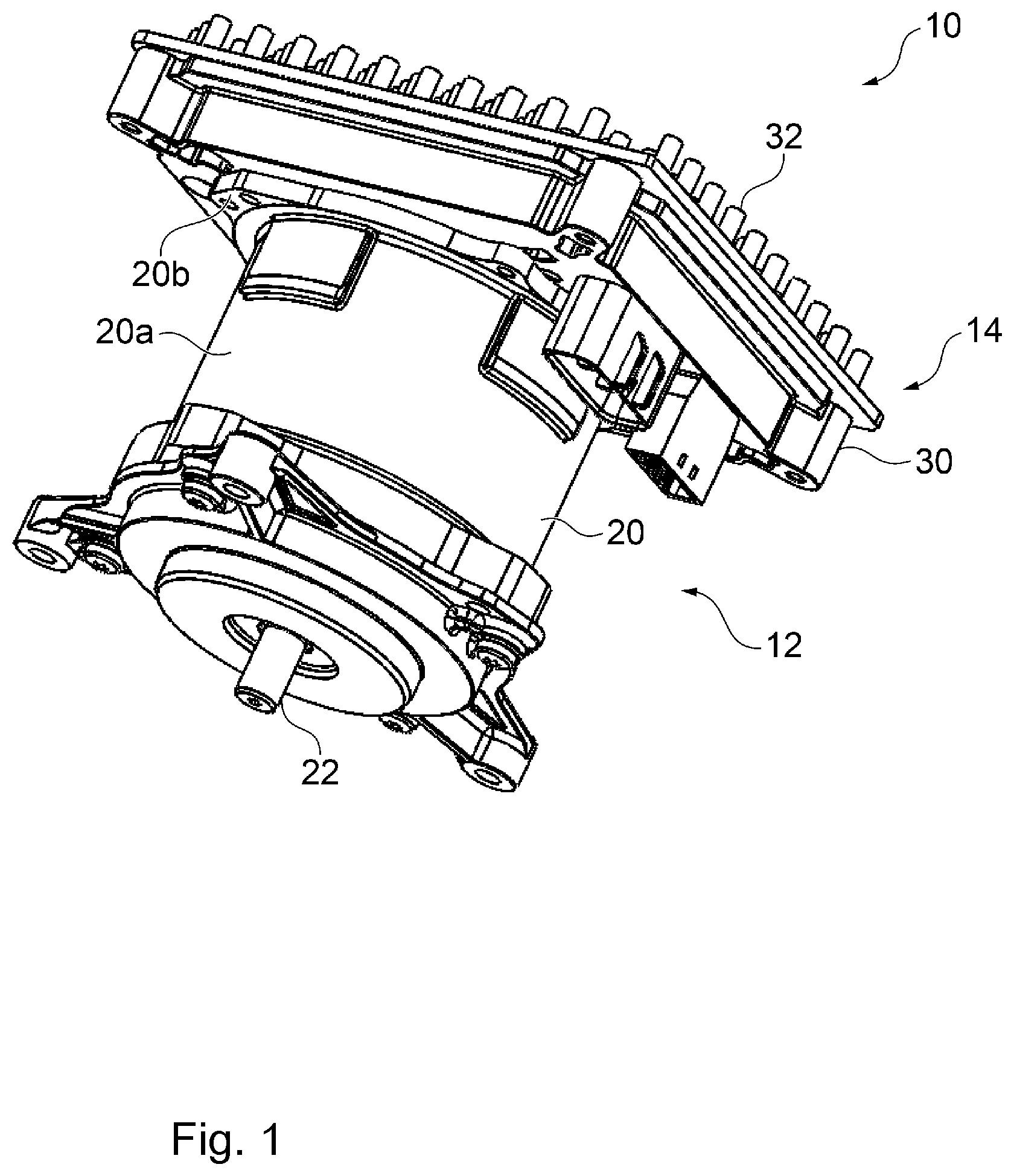
is a perspective view showing a motor unit according to the present embodiment.
is a front view showing the motor unit according to the present embodiment.
is a perspective view showing the cover member.
is a sectional view taken along the P-P line in .
is an enlarged view showing an area Q in .
is a sectional view taken along the R-R line in .
DETAILED DESCRIPTION
is a perspective view showing a motor unit 10 according to the present embodiment. is a front view showing the motor unit 10 according to the present embodiment. The motor unit 10 includes a motor 12 and an electronic control unit 14 . The motor 12 includes a motor housing 20 and a motor shaft 22 . The motor housing 20 has a cylindrical part 20 a . A (non-illustrated) stator composed of a cylindrically wound coil is housed in the cylindrical part 20 a . A (non-illustrated) rotor is further housed in the center of the stator. The rotor is fixed to the motor shaft 22 , which is rotatably supported on the motor housing 20 . The motor shaft 22 has its tip protruding from one end side of the motor housing 20 . A flange 20 b is formed at the other end of the motor housing 20 . An electronic control unit 14 is attached to the flange 20 b by using a fastening tool such as a screw.
The electronic control unit 14 includes a cover member 30 and a heat sink 32 . The below-described control substrate is housed in the interior of the cover member 30 . After the control substrate is housed, the heat sink 32 is attached to the cover member 30 . The heat sink 32 has a large number of fins 32 a for heat radiation. The heat sink 32 externally radiates heat generated by the control substrate housed in the cover member 30 to cool the control substrate.
is a perspective view showing the cover member 30 . In order to make understanding easy, the cover member 30 in a state in which the heat sink 32 and the control substrate are detached is shown. The cover member 30 includes a bottom plate 30 a , a side wall 30 b , a flange 30 c , and an enclosing part 30 d . The bottom plate 30 a is formed to assume a rectangular shape. The side wall 30 b extends from four sides of the bottom plate 30 a perpendicularly to the surface of the bottom plate 30 a . Thus, the cover member 30 is formed to assume a rectangular vessel shape having an opening on a side facing the bottom plate 30 a . The flange 30 c is formed at an end of the side wall 30 b . The heat sink 32 is attached to the flange 30 c.
The bottom plate 30 a has a plurality of (three in the present embodiment) enclosing parts 30 d . The enclosing part 30 d is formed to assume a cylindrical shape perpendicularly extending from the bottom plate 30 a to the same side as the side wall 30 b . The enclosing part 30 d will be described below.
is the sectional view taken along the P-P line in . is the enlarged view showing the area Q in . is the sectional view taken along the R-R line in . The motor 12 further includes a bus bar unit 50 . The bus bar unit 50 has a resin plate 52 and a bus bar 54 . The resin plate 52 extends on a plane perpendicular to the motor shaft 22 . The resin plate 52 is arranged to block the one side of the cylindrical part 20 a of the motor housing 20 in which the stator and the rotor are housed. In the present embodiment, the bus bar 54 is insert-molded in the resin plate 52 . The bus bar 54 may be fixed in the resin plate 52 by another fixing method such as press fitting. The bus bar 54 is formed to assume a shape obtained by bending a long and narrow rectangular sheet metal into an L-shape. The bus bar 54 is fixed on the resin plate 52 in such a manner that the long part is parallel to the motor shaft 22 . The long part of the bus bar 54 is a bus bar terminal 54 a . The bus bar 54 is electrically connected to the coil of the stator. The motor 12 according to the present embodiment is a 3-phase motor and therefore three bus bars 54 are provided. However, needless to say, the number of the bus bars 54 is not limited to three.
The electronic control unit 14 further includes a control substrate 40 . The control substrate 40 controls operation of the motor 12 . The cover member 30 is interposed between the control substrate 40 and the motor 12 . The control substrate 40 has a base substrate 42 and a connection terminal 44 . In the base substrate 42 , various (non-illustrated) electric elements to be used for controlling the motor 12 are mounted. The connection terminal 44 is fitted to the bus bar terminal 54 a and is made to electrically connect the control substrate 40 to the stator. Due to this, the connection terminal 44 is attached to the side, which is opposite to the bus bar unit 50 , of the base substrate 42 . The connection terminal 44 is formed to assume a C-shape whose one end opens. The connection terminal 44 is attached to the base substrate 42 , so that the opening is directed towards the side of the bus bar unit 50 .
A method for assembling the motor unit 10 will be explained. First, the bus bar unit 50 is fixed to the stator and the bus bar 54 is connected to the coil of the stator. The stator, to which the bus bar unit 50 is fixed, is inserted into the motor housing 20 . Then, the rotor fixed to the motor shaft 22 is housed in the center of the stator. The motor 12 is assembled in this manner. At this time, the bus bar terminal 54 a protrudes from the resin plate 52 parallel to the motor shaft 22 .
Meanwhile, the control substrate 40 is fixed to the cover member 30 . The heat sink 32 is attached to the flange 30 c of the cover member 30 . The electronic control unit 14 is assembled in this manner.
Next, the electronic control unit 14 is assembled to the motor 12 . Concretely, the electronic control unit 14 is mounted on the motor 12 , so that the bottom plate 30 a of the cover member 30 faces the resin plate 52 , and the cover member 30 is fixed to the flange 20 b of the motor housing 20 .
The cover member 30 has a through hole 30 e . When the electronic control unit 14 is mounted on the motor 12 , the bus bar terminal 54 a pieces through the through hole 30 e . Then, the bus bar terminal 54 a is inserted into the opening of the connection terminal 44 . In this manner, the connection terminal 44 is fitted to the bus bar terminal 54 a and is made to electrically connect the control substrate 40 to the stator. When dirt and foreign substances enter a fitting location 44 a for the bus bar terminal 54 a and the connection terminal 44 , short-circuiting may occur with respect to the adjacent conductor.
Therefore, the cover member 30 according to the present embodiment has the enclosing part 30 d . The enclosing part 30 d encloses the fitting location 44 a for the bus bar terminal 54 a and the connection terminal 44 , as seen in a piercing direction of the bus bar terminal 54 a , in a state in which the bus bar terminal 54 a is inserted into the connection terminal 44 . The enclosing part 30 d contains the fitting location 44 a in an axial direction. This can thereby suppress entry of dirt and foreign substances into the fitting location 44 a . Therefore, the short-circuiting with respect to the adjacent conductor can be avoided. As described above, the motor 12 according to the present embodiment is a 3-phase motor and therefore three bus bars 54 are provided. Therefore, three enclosing parts 30 d are similarly provided in the cover member 30 according to the present embodiment.
Further, the length of the bus bar terminal 54 a is comparatively long as described above. Therefore, a positional precision of a tip part of the bus bar terminal 54 a becomes worse in a certain case due to a tilt or deformation of the bus bar terminal 54 a . Thus, when the tip part of the bus bar terminal 54 a is inserted as it is into the connection terminal 44 , entanglement may occur between the bus bar terminal 54 a and the connection terminal 44 .
Therefore, the inner surface of the through hole 30 e has a pair of inclined surfaces 30 f . An inclined surface 30 f is tilted in such a manner that, the farther the bus bar terminal 54 a proceeds in a direction of insertion S, the smaller the width becomes. Due to this, the bus bar terminal 54 a can be correctly guided and entanglement at the fitting location 44 a for the bus bar terminal 54 a and the connection terminal 44 can be suppressed. Due to this, increase of electrical resistance and thermal resistance possibly caused by the entanglement can be avoided, so that reliability can be enhanced.
The cover member 30 is composed of resin. This can reduce the thermal influence between the motor 12 and the control substrate 40 in comparison with the case in which the cover member 30 is composed of metal. Therefore, for example, an expensive electric element with high thermal resistance does not need to be mounted on the control substrate 40 , so that the costs can be reduced. The cover member 30 may be composed of metal such as aluminum.
While the present invention has been explained by referring to the embodiment, the present invention is not limited to the above embodiment and appropriately combined or replaced configurations in the embodiment are also included in the present invention. Further, it is also possible to appropriately rearrange the combination and the order of processing in the embodiment as well as to apply modifications such as various design variations based on the skilled person's knowledge. The embodiment, to which the above modifications are applied, can also be included in the scope of the present invention.
Reference signs list: 10 Motor unit, 12 Motor, 14 Electronic control unit, 20 Motor housing, 20 a Cylindrical part, 20 b Flange, 22 Motor shaft, 30 Cover member, 30 a Bottom plate, 30 b Side wall, 30 c Flange, 30 d Enclosing part, 30 e Through hole, 30 f Inclined surface, 32 Heat sink, 32 a Fin, 40 Control substrate, 42 Base substrate, 44 Connection terminal, 44 a Fitting location, 50 Bus bar unit, 52 Resin plate, 54 Bus bar, 54 a Bus bar terminal
Figures (6)
Citations
This patent cites (10)
- US9912208
- US11258330
- US11527935
- US2010/0133935
- US2015/0194857
- US2020/0059141
- US2022/0224195
- US2017157418
- US2020099144
- US2021016222