Abstract
A plurality of electrode conductors included in a first external electrode and a second external electrode of a multilayer coil component includes a first part in a second direction and a second part in a third direction. A first electrode conductor and a third electrode conductor differ in at least any one dimension of four dimensions including a width of the first part, a length of the first part, a width of the second part, and a length of the second part. A second electrode conductor and a fourth electrode conductor differ in at least any one dimension of the four dimensions. The first electrode conductor and the second electrode conductor differ in at least any one dimension of the four dimensions. The third electrode conductor and the fourth electrode conductor differ in at least any one dimension of the four dimensions.
Claims (15)
1 . A multilayer coil component comprising: an element body including a main surface constituting a mounting surface, a first side surface and a second side surface opposing each other in a first direction, and a first end surface and a second end surface opposing each other in a second direction orthogonal to the first direction; a coil disposed inside the element body; and a first external electrode and a second external electrode electrically connected to the coil and disposed on the element body, wherein each of the first external electrode and the second external electrode includes a plurality of electrode conductors arranged in the first direction and connected to each other, wherein each of the plurality of electrode conductors includes a first part extending in the second direction and a second part extending in a third direction orthogonal to the second direction when viewed in the first direction, wherein the plurality of electrode conductors included in the first external electrode include a first electrode conductor and a second electrode conductor adjacent to each other in the first direction, wherein the plurality of electrode conductors included in the second external electrode include a third electrode conductor positioned at the same layer as the first electrode conductor, and a fourth electrode conductor positioned at the same layer as the second electrode conductor, wherein the first electrode conductor and the third electrode conductor differ from each other in at least any one dimension of four dimensions including a width of the first part in the third direction, a length of the first part in the second direction, a width of the second part in the second direction, and a length of the second part in the third direction, wherein the second electrode conductor and the fourth electrode conductor differ from each other in at least any one dimension of the four dimensions, wherein the first electrode conductor and the second electrode conductor differ from each other in at least any one dimension of the four dimensions, and wherein the third electrode conductor and the fourth electrode conductor differ from each other in at least any one dimension of the four dimensions.
Show 14 dependent claims
2 . The multilayer coil component according to claim 1 , wherein the width of the first part of the first electrode conductor is smaller than the width of the first part of the second electrode conductor, wherein the length of the first part of the first electrode conductor is smaller than the length of the first part of the second electrode conductor, wherein the width of the second part of the first electrode conductor is smaller than the width of the second part of the second electrode conductor, and wherein the length of the second part of the first electrode conductor is smaller than the length of the second part of the second electrode conductor.
3 . The multilayer coil component according to claim 1 , wherein the width of the first part of the first electrode conductor is smaller than the width of the first part of the third electrode conductor, wherein the length of the first part of the first electrode conductor is smaller than the length of the first part of the third electrode conductor, wherein the width of the second part of the first electrode conductor is smaller than the width of the second part of the third electrode conductor, and wherein the length of the second part of the first electrode conductor is smaller than the length of the second part of the third electrode conductor.
4 . The multilayer coil component according to claim 2 , wherein the width of the first part of the first electrode conductor is smaller than the width of the first part of the third electrode conductor, wherein the length of the first part of the first electrode conductor is smaller than the length of the first part of the third electrode conductor, wherein the width of the second part of the first electrode conductor is smaller than the width of the second part of the third electrode conductor, and wherein the length of the second part of the first electrode conductor is smaller than the length of the second part of the third electrode conductor.
5 . The multilayer coil component according to claim 1 , wherein the width of the first part of the first electrode conductor is larger than the width of the first part of the second electrode conductor, wherein the length of the first part of the first electrode conductor is larger than the length of the first part of the second electrode conductor, wherein the width of the second part of the first electrode conductor is smaller than the width of the second part of the second electrode conductor, and wherein the length of the second part of the first electrode conductor is smaller than the length of the second part of the second electrode conductor.
6 . The multilayer coil component according to claim 5 , wherein the width of the first part of the first electrode conductor is larger than the width of the first part of the third electrode conductor, wherein the length of the first part of the first electrode conductor is larger than the length of the first part of the third electrode conductor, wherein the width of the second part of the first electrode conductor is smaller than the width of the second part of the third electrode conductor, and wherein the length of the second part of the first electrode conductor is smaller than the length of the second part of the third electrode conductor.
7 . The multilayer coil component according to claim 1 , wherein the plurality of electrode conductors included in the first external electrode include a fifth electrode conductor and a sixth electrode conductor adjacent to each other in the first direction, wherein the plurality of electrode conductors included in the second external electrode include a seventh electrode conductor positioned at the same layer as the fifth electrode conductor, and an eighth electrode conductor positioned at the same layer as the sixth electrode conductor, wherein the first electrode conductor is closest to the first side surface of the plurality of electrode conductors included in the first external electrode, and the fifth electrode conductor is closest to the second side surface of the plurality of electrode conductors included in the first external electrode, wherein the third electrode conductor is closest to the first side surface of the plurality of electrode conductors included in the second external electrode, and the seventh electrode conductor is closest to the second side surface of the plurality of electrode conductors included in the second external electrode, wherein the fifth electrode conductor and the seventh electrode conductor differ from each other in at least any one dimension of the four dimensions, wherein the sixth electrode conductor and the eighth electrode conductor differ from each other in at least any one dimension of the four dimensions, wherein the fifth electrode conductor and the sixth electrode conductor differ from each other in at least any one dimension of the four dimensions, and wherein the seventh electrode conductor and the eighth electrode conductor differ from each other in at least any one dimension of the four dimensions.
8 . The multilayer coil component according to claim 7 , wherein the length of the first part of the first electrode conductor is larger than the length of the first part of the second electrode conductor, wherein the length of the second part of the first electrode conductor is smaller than the length of the second part of the second electrode conductor, wherein the length of the first part of the fifth electrode conductor is smaller than the length of the first part of the sixth electrode conductor, and wherein the length of the second part of the fifth electrode conductor is larger than the length of the second part of the sixth electrode conductor.
9 . The multilayer coil component according to claim 7 , wherein the coil includes a plurality of coil conductors arranged in the first direction and connected to each other, wherein the plurality of coil conductors include a first coil conductor positioned at the same layer as the first electrode conductor and the third electrode conductor, and a second coil conductor positioned at the same layer as the fifth electrode conductor and the seventh electrode conductor, wherein each of the first coil conductor and the second coil conductor includes a third part constituting a portion of an annular trajectory in the coil, and a fourth part being continuous with the third part and protruding to an outward side of the annular trajectory when viewed in the first direction, wherein the fourth part of the first coil conductor is connected to the second part of the third electrode conductor, and the fourth part of the second coil conductor is connected to the second part of the fifth electrode conductor, wherein the length of the second part of the third electrode conductor is smaller than the length of the second part of the fourth electrode conductor, and wherein the length of the second part of the fifth electrode conductor is smaller than the length of the second part of the sixth electrode conductor.
10 . The multilayer coil component according to claim 8 , wherein the coil includes a plurality of coil conductors arranged in the first direction and connected to each other, wherein the plurality of coil conductors include a first coil conductor positioned at the same layer as the first electrode conductor and the third electrode conductor, and a second coil conductor positioned at the same layer as the fifth electrode conductor and the seventh electrode conductor, wherein each of the first coil conductor and the second coil conductor includes a third part constituting a portion of an annular trajectory in the coil, and a fourth part being continuous with the third part and protruding to an outward side of the annular trajectory when viewed in the first direction, wherein the fourth part of the first coil conductor is connected to the second part of the third electrode conductor, and the fourth part of the second coil conductor is connected to the second part of the fifth electrode conductor, wherein the length of the second part of the third electrode conductor is smaller than the length of the second part of the fourth electrode conductor, and wherein the length of the second part of the fifth electrode conductor is smaller than the length of the second part of the sixth electrode conductor.
11 . The multilayer coil component according to claim 1 , wherein the width of the first part of the first electrode conductor is larger than the width of the first part of the second electrode conductor, wherein the length of the first part of the first electrode conductor is smaller than the length of the first part of the second electrode conductor, wherein the width of the second part of the first electrode conductor is smaller than the width of the second part of the second electrode conductor, and wherein the length of the second part of the first electrode conductor is larger than the length of the second part of the second electrode conductor.
12 . The multilayer coil component according to claim 11 , wherein the width of the first part of the first electrode conductor is larger than the width of the first part of the third electrode conductor, wherein the length of the first part of the first electrode conductor is smaller than the length of the first part of the third electrode conductor, wherein the width of the second part of the first electrode conductor is smaller than the width of the second part of the third electrode conductor, and wherein the length of the second part of the first electrode conductor is larger than the length of the second part of the third electrode conductor.
13 . The multilayer coil component according to claim 1 , wherein the coil includes a plurality of coil conductors arranged in the first direction and connected to each other, wherein the plurality of coil conductors include a first coil conductor positioned at the same layer as the first electrode conductor and the third electrode conductor, wherein a shortest separation distance between the second part of the first electrode conductor and the first coil conductor is smaller than a shortest separation distance between the second part of the third electrode conductor and the first coil conductor, wherein the width of the second part of the first electrode conductor is smaller than the width of the second part of the third electrode conductor, and wherein the length of the second part of the first electrode conductor is smaller than the length of the second part of the third electrode conductor.
14 . The multilayer coil component according to claim 13 , wherein the plurality of coil conductors include a third coil conductor positioned at the same layer as the second electrode conductor and the fourth electrode conductor, wherein the shortest separation distance between the second part of the first electrode conductor and the first coil conductor is smaller than a shortest separation distance between the second part of the second electrode conductor and the third coil conductor, wherein the width of the second part of the first electrode conductor is smaller than the width of the second part of the second electrode conductor, and wherein the length of the second part of the first electrode conductor is smaller than the length of the second part of the second electrode conductor.
15 . The multilayer coil component according to claim 1 , wherein the first part of each of the plurality of electrode conductors includes a first end and a second end in the second direction, wherein the second part of each of the plurality of electrode conductors includes a first end and a second end in the third direction, wherein the first end of the first part and the first end of the second part are continuous with each other, and wherein a surface of each of the second end of the first part and the second end of the second part is curved when viewed in the first direction.
Full Description
Show full text →
BACKGROUND OF THE INVENTION
1. Field of the Invention
The present disclosure relates to a multilayer coil component.
2. Description of Related Art
Known multilayer coil components include an element body, a coil that is disposed inside the element body, and a pair of external electrodes that each include a plurality of electrode conductors connected to each other and disposed on the element body (for example, refer to Japanese Unexamined Patent Publication No. 2017-073536).
SUMMARY OF THE INVENTION
A multilayer coil component is mounted on an electronic instrument. For example, an electronic instrument includes a circuit board and an electronic component. When a multilayer coil component is mounted on an electronic instrument, an external force from the electronic instrument may act on an external electrode. In a multilayer coil component in which a fixing strength of an external electrode with respect to an element body is insufficient, when an external force from an electronic instrument acts on the external electrode, the external electrode may peel off from the element body. When an external electrode peels off from an element body, a multilayer coil component tends not to function as a coil.
An object of an aspect of the present disclosure is to provide a multilayer coil component in which a fixing strength of an external electrode with respect to an element body is improved.
A multilayer coil component according to one aspect of the present disclosure includes an element body, a coil, and a first external electrode and a second external electrode. The element body includes a main surface constituting a mounting surface, a first side surface and a second side surface opposing each other in a first direction, and a first end surface and a second end surface opposing each other in a second direction orthogonal to the first direction. The coil is disposed inside the element body. The first external electrode and the second external electrode are electrically connected to the coil and disposed on the element body. Each of the first external electrode and the second external electrode includes a plurality of electrode conductors arranged in the first direction and connected to each other. Each of the plurality of electrode conductors includes a first part extending in the second direction and a second part extending in a third direction orthogonal to the second direction when viewed in the first direction. The plurality of electrode conductors included in the first external electrode include a first electrode conductor and a second electrode conductor adjacent to each other in the first direction. The plurality of electrode conductors included in the second external electrode include a third electrode conductor positioned at the same layer as the first electrode conductor, and a fourth electrode conductor positioned at the same layer as the second electrode conductor. The first electrode conductor and the third electrode conductor differ from each other in at least any one dimension of four dimensions including a width of the first part in the third direction, a length of the first part in the second direction, a width of the second part in the second direction, and a length of the second part in the third direction. The second electrode conductor and the fourth electrode conductor differ from each other in at least any one dimension of the four dimensions. The first electrode conductor and the second electrode conductor differ from each other in at least any one dimension of the four dimensions. The third electrode conductor and the fourth electrode conductor differ from each other in at least any one dimension of the four dimensions.
In the one aspect, the first electrode conductor differs from the third electrode conductor positioned in the same layer and the second electrode conductor adjacent thereto in the first direction in shape. The third electrode conductor differs from the fourth electrode conductor adjacent thereto in the first direction in shape. The second electrode conductor differs from the fourth electrode conductor positioned in the same layer in shape. In this case, surfaces of the first external electrode and the second external electrode opposing the element body have a complicated shape. The surfaces opposing the element body are surfaces coming into contact with the element body. Accordingly, an area of the first external electrode coming into contact with the element body and an area of the second external electrode coming into contact with the element body increase. Therefore, in the one aspect, fixing strengths of the first external electrode and the second external electrode with respect to the element body are improved.
In the one aspect, the width of the first part of the first electrode conductor may be smaller than the width of the first part of the second electrode conductor. The length of the first part of the first electrode conductor may be smaller than the length of the first part of the second electrode conductor. The width of the second part of the first electrode conductor may be smaller than the width of the second part of the second electrode conductor. The length of the second part of the first electrode conductor may be smaller than the length of the second part of the second electrode conductor.
In a constitution in which the width of the first part of the first electrode conductor is smaller than the width of the first part of the second electrode conductor, the length of the first part of the first electrode conductor is smaller than the length of the first part of the second electrode conductor, the width of the second part of the first electrode conductor is smaller than the width of the second part of the second electrode conductor, and the length of the second part of the first electrode conductor is smaller than the length of the second part of the second electrode conductor, the surface of the first external electrode opposing the element body has a more complicated shape, and the area of the first external electrode coming into contact with the element body further increases. As a result, the fixing strength of the first external electrode with respect to the element body is further improved.
In the one aspect, the width of the first part of the first electrode conductor may be smaller than the width of the first part of the third electrode conductor. The length of the first part of the first electrode conductor may be smaller than the length of the first part of the third electrode conductor. The width of the second part of the first electrode conductor may be smaller than the width of the second part of the third electrode conductor. The length of the second part of the first electrode conductor may be smaller than the length of the second part of the third electrode conductor.
In a constitution in which the width of the first part of the first electrode conductor is smaller than the width of the first part of the third electrode conductor, the length of the first part of the first electrode conductor is smaller than the length of the first part of the third electrode conductor, the width of the second part of the first electrode conductor is smaller than the width of the second part of the third electrode conductor, and the length of the second part of the first electrode conductor is smaller than the length of the second part of the third electrode conductor, the surfaces of the first external electrode and the second external electrode opposing the element body may have a more complicated shape. When the surfaces of the first external electrode and the second external electrode opposing the element body have a more complicated shape, the area of the first external electrode coming into contact with the element body and the area of the second external electrode coming into contact with the element body further increase. As a result, the fixing strengths of the first external electrode and the second external electrode with respect to the element body are further improved.
In the one aspect, the width of the first part of the first electrode conductor may be larger than the width of the first part of the second electrode conductor. The length of the first part of the first electrode conductor may be larger than the length of the first part of the second electrode conductor. The width of the second part of the first electrode conductor may be smaller than the width of the second part of the second electrode conductor. The length of the second part of the first electrode conductor may be smaller than the length of the second part of the second electrode conductor.
In a constitution in which the width of the first part of the first electrode conductor is larger than the width of the first part of the second electrode conductor, the length of the first part of the first electrode conductor is larger than the length of the first part of the second electrode conductor, the width of the second part of the first electrode conductor is smaller than the width of the second part of the second electrode conductor, and the length of the second part of the first electrode conductor is smaller than the length of the second part of the second electrode conductor, the surface of the first external electrode opposing the element body has a more complicated shape, and the area of the first external electrode coming into contact with the element body further increases. As a result, the fixing strength of the first external electrode with respect to the element body is further improved.
In the one aspect, the width of the first part of the first electrode conductor may be larger than the width of the first part of the third electrode conductor. The length of the first part of the first electrode conductor may be larger than the length of the first part of the third electrode conductor. The width of the second part of the first electrode conductor may be smaller than the width of the second part of the third electrode conductor. The length of the second part of the first electrode conductor may be smaller than the length of the second part of the third electrode conductor.
In a constitution in which the width of the first part of the first electrode conductor is larger than the width of the first part of the third electrode conductor, the length of the first part of the first electrode conductor is larger than the length of the first part of the third electrode conductor, the width of the second part of the first electrode conductor is smaller than the width of the second part of the third electrode conductor, and the length of the second part of the first electrode conductor is smaller than the length of the second part of the third electrode conductor, the surfaces of the first external electrode and the second external electrode opposing the element body may have a more complicated shape. When the surfaces of the first external electrode and the second external electrode opposing the element body have a more complicated shape, the area of the first external electrode coming into contact with the element body and the area of the second external electrode coming into contact with the element body further increase. As a result, the fixing strengths of the first external electrode and the second external electrode with respect to the element body are further improved.
In the one aspect, the plurality of electrode conductors included in the first external electrode may include a fifth electrode conductor and a sixth electrode conductor adjacent to each other in the first direction. The plurality of electrode conductors included in the second external electrode may include a seventh electrode conductor positioned at the same layer as the fifth electrode conductor, and an eighth electrode conductor positioned at the same layer as the sixth electrode conductor. The first electrode conductor may be closest to the first side surface of the plurality of electrode conductors included in the first external electrode, and the fifth electrode conductor may be closest to the second side surface of the plurality of electrode conductors included in the first external electrode. The third electrode conductor may be closest to the first side surface of the plurality of electrode conductors included in the second external electrode, and the seventh electrode conductor may be closest to the second side surface of the plurality of electrode conductors included in the second external electrode. The fifth electrode conductor and the seventh electrode conductor may differ from each other in at least any one dimension of the four dimensions. The sixth electrode conductor and the eighth electrode conductor may differ from each other in at least any one dimension of the four dimensions. The fifth electrode conductor and the sixth electrode conductor may differ from each other in at least any one dimension of the four dimensions. The seventh electrode conductor and the eighth electrode conductor may differ from each other in at least any one dimension of the four dimensions.
In a constitution in which the fifth electrode conductor and the seventh electrode conductor differ from each other in at least any one dimension of the four dimensions, the sixth electrode conductor and the eighth electrode conductor differ from each other in at least any one dimension of the four dimensions, the fifth electrode conductor and the sixth electrode conductor differ from each other in at least any one dimension of the four dimensions, and the seventh electrode conductor and the eighth electrode conductor differ from each other in at least any one dimension of the four dimensions, the fifth electrode conductor differs from the seventh electrode conductor positioned in the same layer and the sixth electrode conductor adjacent thereto in the first direction in shape. The seventh electrode conductor differs from the eighth electrode conductor adjacent thereto in the first direction in shape. The sixth electrode conductor differs from the eighth electrode conductor positioned in the same layer in shape. In this case, the surfaces of the first external electrode and the second external electrode opposing the element body have a more complicated shape. Accordingly, the area of the first external electrode coming into contact with the element body and the area of the second external electrode coming into contact with the element body further increase. As a result, the fixing strengths of the first external electrode and the second external electrode with respect to the element body are further improved.
In the one aspect, the length of the first part of the first electrode conductor may be larger than the length of the first part of the second electrode conductor. The length of the second part of the first electrode conductor may be smaller than the length of the second part of the second electrode conductor. The length of the first part of the fifth electrode conductor may be smaller than the length of the first part of the sixth electrode conductor. The length of the second part of the fifth electrode conductor may be larger than the length of the second part of the sixth electrode conductor.
In a constitution in which the length of the first part of the first electrode conductor is larger than the length of the first part of the second electrode conductor, the length of the second part of the first electrode conductor is smaller than the length of the second part of the second electrode conductor, the length of the first part of the fifth electrode conductor is smaller than the length of the first part of the sixth electrode conductor, and the length of the second part of the fifth electrode conductor is larger than the length of the second part of the sixth electrode conductor, the surface of the first external electrode opposing the element body has a more complicated shape, and the area of the first external electrode coming into contact with the element body further increases. As a result, the fixing strength of the first external electrode with respect to the element body is further improved.
In the one aspect, the coil may include a plurality of coil conductors arranged in the first direction and connected to each other. The plurality of coil conductors may include a first coil conductor positioned at the same layer as the first electrode conductor and the third electrode conductor, and a second coil conductor positioned at the same layer as the fifth electrode conductor and the seventh electrode conductor. Each of the first coil conductor and the second coil conductor may include a third part constituting a portion of an annular trajectory in the coil, and a fourth part being continuous with the third part and protruding to an outward side of the annular trajectory when viewed in the first direction. The fourth part of the first coil conductor may be connected to the second part of the third electrode conductor, and the fourth part of the second coil conductor may be connected to the second part of the fifth electrode conductor. The length of the second part of the third electrode conductor may be smaller than the length of the second part of the fourth electrode conductor. The length of the second part of the fifth electrode conductor may be smaller than the length of the second part of the sixth electrode conductor.
When the first coil conductor includes the fourth part connected to the third electrode conductor and the second coil conductor includes the fourth part connected to the fifth electrode conductor, a volume of the element body is smaller in a layer in which the first coil conductor is positioned and a layer in which the second coil conductor is positioned than those in other layers by an amount corresponding to the fourth part. However, in the foregoing constitution in which the length of the second part of the third electrode conductor is smaller than the length of the second part of the fourth electrode conductor and the length of the second part of the fifth electrode conductor is smaller than the length of the second part of the sixth electrode conductor, volumes of the third electrode conductor and the fifth electrode conductor are reduced. Therefore, the volume of the element body increases in the layer in which the first coil conductor is positioned and the layer in which the second coil conductor is positioned. As a result of increase in volume of the element body, the strength of the multilayer coil component is improved. Since volumes of the external electrodes are smaller than the volume of the element body, cracking tends not to occur in the element body.
In the one aspect, the width of the first part of the first electrode conductor may be larger than the width of the first part of the second electrode conductor. The length of the first part of the first electrode conductor may be smaller than the length of the first part of the second electrode conductor. The width of the second part of the first electrode conductor may be smaller than the width of the second part of the second electrode conductor. The length of the second part of the first electrode conductor may be larger than the length of the second part of the second electrode conductor.
In a constitution in which the width of the first part of the first electrode conductor is larger than the width of the first part of the second electrode conductor, the length of the first part of the first electrode conductor is smaller than the length of the first part of the second electrode conductor, the width of the second part of the first electrode conductor is smaller than the width of the second part of the second electrode conductor, and the length of the second part of the first electrode conductor is larger than the length of the second part of the second electrode conductor, the surface of the first external electrode opposing the element body has a more complicated shape, and the area of the first external electrode coming into contact with the element body further increases. As a result, the fixing strength of the first external electrode with respect to the element body is further improved.
In the one aspect, the width of the first part of the first electrode conductor may be larger than the width of the first part of the third electrode conductor. The length of the first part of the first electrode conductor may be smaller than the length of the first part of the third electrode conductor. The width of the second part of the first electrode conductor may be smaller than the width of the second part of the third electrode conductor. The length of the second part of the first electrode conductor may be larger than the length of the second part of the third electrode conductor.
In a constitution in which the width of the first part of the first electrode conductor is larger than the width of the first part of the third electrode conductor, the length of the first part of the first electrode conductor is smaller than the length of the first part of the third electrode conductor, the width of the second part of the first electrode conductor is smaller than the width of the second part of the third electrode conductor, and the length of the second part of the first electrode conductor is larger than the length of the second part of the third electrode conductor, the surfaces of the first external electrode and the second external electrode opposing the element body may have a more complicated shape. When the surfaces of the first external electrode and the second external electrode opposing the element body have a more complicated shape, the area of the first external electrode coming into contact with the element body and the area of the second external electrode coming into contact with the element body further increase. As a result, the fixing strengths of the first external electrode and the second external electrode with respect to the element body are further improved.
In the one aspect, the coil may include a plurality of coil conductors arranged in the first direction and connected to each other. The plurality of coil conductors may include a first coil conductor positioned at the same layer as the first electrode conductor and the third electrode conductor. A shortest separation distance between the second part of the first electrode conductor and the first coil conductor may be smaller than a shortest separation distance between the second part of the third electrode conductor and the first coil conductor. The width of the second part of the first electrode conductor may be smaller than the width of the second part of the third electrode conductor. The length of the second part of the first electrode conductor may be smaller than the length of the second part of the third electrode conductor.
In a constitution in which the shortest separation distance between the second part of the first electrode conductor and the first coil conductor is smaller than the shortest separation distance between the second part of the third electrode conductor and the first coil conductor, the width of the second part of the first electrode conductor is smaller than the width of the second part of the third electrode conductor, and the length of the second part of the first electrode conductor is smaller than the length of the second part of the third electrode conductor, a volume of the second part of the first electrode conductor positioned close to the first coil conductor is further reduced than a volume of the second part of the third electrode conductor, and increase in stray capacitance generated between the second part of the first electrode conductor and the first coil conductor is curbed.
In the one aspect, the plurality of coil conductors may include a third coil conductor positioned at the same layer as the second electrode conductor and the fourth electrode conductor. The shortest separation distance between the second part of the first electrode conductor and the first coil conductor may be smaller than a shortest separation distance between the second part of the second electrode conductor and the third coil conductor. The width of the second part of the first electrode conductor may be smaller than the width of the second part of the second electrode conductor. The length of the second part of the first electrode conductor may be smaller than the length of the second part of the second electrode conductor.
In a constitution in which the shortest separation distance between the second part of the first electrode conductor and the first coil conductor is smaller than the shortest separation distance between the second part of the second electrode conductor and the third coil conductor, the width of the second part of the first electrode conductor is smaller than the width of the second part of the second electrode conductor, and the length of the second part of the first electrode conductor is smaller than the length of the second part of the second electrode conductor, the volume of the second part of the first electrode conductor positioned close to the coil conductor in the same layer is further reduced than a volume of the second part of the second electrode conductor, and increase in stray capacitance generated between the second part of the first electrode conductor and the first coil conductor is curbed.
In the one aspect, the first part of each of the plurality of electrode conductors may include a first end and a second end in the second direction. The second part of each of the plurality of electrode conductors may include a first end and a second end in the third direction. The first end of the first part and the first end of the second part may be continuous with each other. A surface of each of the second end of the first part and the second end of the second part may be curved when viewed in the first direction.
In a constitution in which the surface of each of the second end of the first part and the second end of the second part is curved, compared to a constitution in which the surface of each of the second end of the first part and the second end of the second part is not curved and includes corner portions projecting to the inward side of the element body, the volume of each of the electrode conductors may be reduced. When the volume of each of the electrode conductors is reduced, the volume of the element body relatively increases, and the strength of the multilayer coil component is improved. When the volume of each of the electrode conductors is reduced, the stray capacitance generated between each of the electrode conductors and the coil is reduced.
The present invention will become more fully understood from the detailed description given hereinafter and the accompanying drawings which are given by way of illustration only, and thus are not to be considered as limiting the present invention.
Further scope of applicability of the present invention will become apparent from the detailed description given hereinafter. However, it should be understood that the detailed description and specific examples, while indicating embodiments of the invention, are given by way of illustration only, since various changes and modifications within the spirit and scope of the invention will become apparent to those skilled in the art from this detailed description.
BRIEF DESCRIPTION OF THE DRAWINGS
is a perspective view illustrating a multilayer coil component according to a first embodiment;
is a plan view of the multilayer coil component according to the first embodiment viewed from a main surface side;
is a plan view of the multilayer coil component according to the first embodiment viewed from one end surface side;
is a plan view of the multilayer coil component according to the first embodiment viewed from the other end surface side;
is an exploded view illustrating a constitution of the multilayer coil component according to the first embodiment;
is a view illustrating a constitution of a coil conductor and electrode conductors;
is a view illustrating a constitution of another coil conductor and other electrode conductors;
is a plan view of a multilayer coil component according to a second embodiment viewed from the main surface side;
is a plan view of the multilayer coil component according to the second embodiment viewed from one end surface side;
is a plan view of the multilayer coil component according to the second embodiment viewed from the other end surface side;
is an exploded view illustrating a constitution of the multilayer coil component according to the second embodiment;
is a view illustrating a constitution of electrode conductors;
is a view illustrating a constitution of other electrode conductors;
is a view illustrating a constitution of other electrode conductors;
is a view illustrating a constitution of other electrode conductors;
is an exploded view illustrating a constitution of a multilayer coil component according to a third embodiment;
is a view illustrating a constitution of electrode conductors;
is a view illustrating a constitution of other electrode conductors;
is a view illustrating a constitution of other electrode conductors;
is a view illustrating a constitution of other electrode conductors;
is an exploded view illustrating a constitution of a multilayer coil component according to a fourth embodiment;
is a view illustrating a constitution of electrode conductors;
is a view illustrating a constitution of other electrode conductors;
is a view illustrating a constitution of other electrode conductors;
is an exploded view illustrating a constitution of a multilayer coil component according to a sixth embodiment;
is a view illustrating a constitution of electrode conductors; and
is a view illustrating a constitution of other electrode conductors.
DETAILED DESCRIPTION OF EMBODIMENTS
Hereinafter, embodiments of the present invention will be described in detail with reference to the accompanying drawings. In the following description, the same elements or elements having the same functions are denoted with the same reference numerals and overlapped explanation is omitted.
First Embodiment
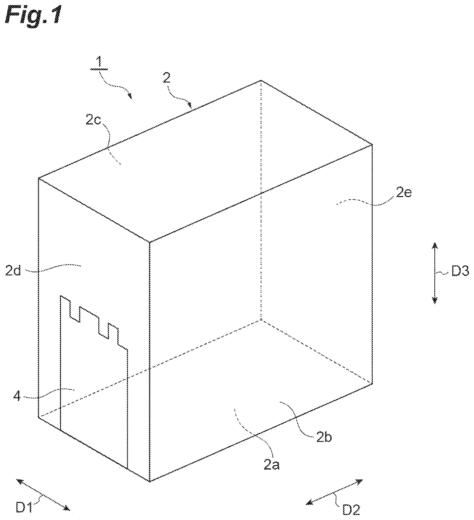
A multilayer coil component 1 according to a first embodiment will be described with reference to to 5 . is a perspective view illustrating the multilayer coil component 1 . is a plan view of the multilayer coil component 1 viewed from a main surface 2 a side. is a plan view of the multilayer coil component 1 viewed from an end surface 2 d side. is a plan view of the multilayer coil component 1 viewed from an end surface 2 e side. is an exploded view illustrating a constitution of the multilayer coil component 1 . The multilayer coil component 1 includes an element body 2 , a coil 3 , and a pair of external electrodes 4 and 5 .
The element body 2 has a rectangular parallelepiped shape. A rectangular parallelepiped shape includes a rectangular shape in which corner portions and ridgeline portions are chamfered, and a rectangular shape in which corner portions and ridgeline portions are rounded. The element body 2 includes a main surface 2 a , side surfaces 2 b and 2 c , and end surfaces 2 d and 2 e . The side surface 2 b and the side surface 2 c oppose each other. For example, when the side surface 2 b constitutes a first side surface, the side surface 2 c constitutes a second side surface. The end surface 2 d and the end surface 2 e oppose each other. For example, when the end surface 2 d constitutes a first end surface, the end surface 2 e constitutes a second end surface. Hereinafter, a direction in which the side surfaces 2 b and 2 c oppose each other will be referred to as a first direction D 1 , a direction in which the end surfaces 2 d and 2 e oppose each other will be referred to as a second direction D 2 , and a direction perpendicular to the main surface 2 a will be referred to as a third direction D 3 . The first direction D 1 , the second direction D 2 , and the third direction D 3 are orthogonal to each other.
The main surface 2 a extends in the first direction D 1 and the second direction D 2 . The pair of side surfaces 2 b and 2 c extend in the second direction D 2 and the third direction D 3 . The pair of end surfaces 2 d and 2 e extend in the first direction D 1 and the third direction D 3 . The main surface 2 a connects the side surface 2 b and the side surface 2 c to each other. The main surface 2 a connects the end surface 2 d and the end surface 2 e to each other. For example, the multilayer coil component 1 is subjected to solder-mounting on an electronic instrument. For example, an electronic instrument is a circuit board or an electronic component. In the multilayer coil component 1 , the main surface 2 a constitutes a mounting surface opposing an electronic instrument.
The element body 2 includes a plurality of insulator layers 21 . The element body 2 includes the plurality of insulator layers 21 stacked in the first direction D 1 . In an actual element body 2 , each of the insulator layers 21 may be integrated to the extent that a boundary between the insulator layers 21 cannot be visually recognized. For example, each of the insulator layers 21 includes a magnetic material. Examples of a magnetic material include a Ni-Cu-Zn-based ferrite material, a Ni-Cu-Zn-Mg-based ferrite material, and a Ni-Cu-based ferrite material. For example, each of the insulator layers 21 is constituted of a sintered body of a green sheet including a magnetic material. A magnetic material constituting each of the insulator layers 21 may include a Fe alloy. Each of the insulator layers 21 may include a non-magnetic material. Examples of a non-magnetic material include a glass-ceramic material and a dielectric material.
The coil 3 is disposed inside the element body 2 . An axial direction of the coil 3 extends in the first direction D 1 . The coil 3 includes a plurality of coil conductors 31 , 32 , 33 , 34 , 35 , 36 , and 37 . The coil 3 includes a plurality of coil conductors 31 to 37 stacked in the first direction D 1 . The coil conductor 31 , the coil conductor 32 , the coil conductor 33 , the coil conductor 34 , the coil conductor 35 , the coil conductor 36 , and the coil conductor 37 are stacked in a direction toward the side surface 2 c from the side surface 2 b in this order. The plurality of coil conductors 31 to 37 are arranged in the first direction D 1 , that is, the coil axis direction of the coil 3 .
The coil conductor 31 and the coil conductor 37 are outermost coil conductors positioned on the outermost sides in the first direction D 1 of the plurality of coil conductors 31 to 37 . The coil conductor 31 and the coil conductor 37 are positioned at the ends of the coil 3 in the coil axis direction of the coil 3 . The coil conductor 31 is closest to the side surface 2 b of the plurality of coil conductors 31 to 37 . The coil conductor 37 is closest to the side surface 2 c of the plurality of coil conductors 31 to 37 . For example, when the coil conductor 31 constitutes a first coil conductor, the coil conductor 37 constitutes a second coil conductor. The plurality of coil conductors 32 to 36 are positioned between the coil conductor 31 and the coil conductor 37 in the first direction D 1 .
The plurality of coil conductors 31 to 37 are connected to each other. The plurality of coil conductors 31 to 37 being connected to each other denote that the plurality of coil conductors 31 to 37 are electrically or physically connected to each other. In an actual coil 3 , the coil conductors 31 to 37 may be integrated to the extent that the boundaries between the respective coil conductors 31 to 37 cannot be visually recognized. Each of the coil conductors 31 to 37 includes an electrically conductive material. For example, an electrically conductive material is Ag or Pd. For example, each of the coil conductors 31 to 37 is constituted as a sintered body of an electrically conductive paste including an electrically conductive material powder. For example, an electrically conductive material powder is Ag powder or Pd powder.
The pair of external electrodes 4 and 5 are electrically connected to the coil 3 and disposed on the element body 2 . The pair of external electrodes 4 and 5 are respectively disposed at both end portions of the element body 2 in the second direction D 2 . The pair of external electrodes 4 and 5 are separated from each other in the second direction D 2 . The external electrode 4 is disposed on the end surface 2 d side of the element body 2 . The external electrode 5 is disposed on the end surface 2 e side of the element body 2 . Each of the external electrodes 4 and 5 is buried in the element body 2 . Each of the external electrodes 4 and 5 has an L-shape when viewed in the first direction D 1 . The external electrode 4 is exposed from the element body 2 on only the main surface 2 a and the end surface 2 d . The surface of the external electrode 4 exposed from the element body 2 is flush with the main surface 2 a and the end surface 2 d . The external electrode 5 is exposed from the element body 2 on only the main surface 2 a and the end surface 2 e . The surface of the external electrode 5 exposed from the element body 2 is flush with the main surface 2 a and the end surface 2 e . For example, when the external electrode 4 constitutes a first external electrode, the external electrode 5 constitutes a second external electrode.
The external electrode 4 includes a plurality of electrode conductors 41 , 42 , 43 , 44 , 45 , 46 , and 47 . The external electrode 4 includes a plurality of electrode conductors 41 to 47 stacked in the first direction D 1 . The electrode conductor 41 , the electrode conductor 42 , the electrode conductor 43 , the electrode conductor 44 , the electrode conductor 45 , the electrode conductor 46 , and the electrode conductor 47 are stacked in a direction toward the side surface 2 c from the side surface 2 b in this order. The plurality of electrode conductors 41 to 47 are arranged in the first direction D 1 , that is, the coil axis direction of the coil 3 . The electrode conductor 41 and the electrode conductor 42 are adjacent to each other in the first direction D 1 . For example, when the electrode conductor 41 constitutes a first electrode conductor, the electrode conductor 42 constitutes a second electrode conductor. The electrode conductor 46 and the electrode conductor 47 are adjacent to each other in the first direction D 1 . For example, when the electrode conductor 46 constitutes a sixth electrode conductor, the electrode conductor 47 constitutes a fifth electrode conductor.
The electrode conductor 41 and the electrode conductor 47 are outermost electrode conductors positioned on the outermost sides in the first direction D 1 of the plurality of electrode conductors 41 to 47 . The electrode conductor 41 and the electrode conductor 47 are positioned at the ends of the external electrode 4 in the first direction D 1 . The electrode conductor 41 is closest to the side surface 2 b of the plurality of electrode conductors 41 to 47 . The electrode conductor 47 is closest to the side surface 2 c of the plurality of electrode conductors 41 to 47 . The electrode conductor 41 is positioned in the same layer as the coil conductor 31 . The electrode conductor 47 is positioned in the same layer as the coil conductor 37 . The plurality of electrode conductors 42 to 46 are positioned between the electrode conductor 41 and the electrode conductor 47 in the first direction D 1 . The plurality of electrode conductors 42 to 46 are positioned in the same layer as the plurality of coil conductors 32 to 36 .
The plurality of electrode conductors 41 to 47 are connected to each other. The plurality of electrode conductors 41 to 47 being connected to each other denote that the plurality of electrode conductors 41 to 47 are electrically or physically connected to each other. In an actual external electrode 4 , the electrode conductors 41 to 47 may be integrated to the extent that the boundaries between the respective electrode conductors 41 to 47 cannot be visually recognized. Each of the electrode conductors 41 to 47 includes an electrically conductive material. For example, an electrically conductive material is Ag or Pd. For example, each of the electrode conductors 41 to 47 is constituted as a sintered body of an electrically conductive paste including an electrically conductive material powder. For example, an electrically conductive material powder is Ag powder or Pd powder. A material of each of the electrode conductors 41 to 47 may be the same as the material of each of the coil conductors 31 to 37 .
The external electrode 5 includes a plurality of electrode conductors 51 , 52 , 53 , 54 , 55 , 56 , and 57 . The external electrode 5 includes a plurality of electrode conductors 51 to 57 stacked in the first direction D 1 . The electrode conductor 51 , the electrode conductor 52 , the electrode conductor 53 , the electrode conductor 54 , the electrode conductor 55 , the electrode conductor 56 , and the electrode conductor 57 are stacked in a direction toward the side surface 2 c from the side surface 2 b in this order. The plurality of electrode conductors 51 to 57 are arranged in the first direction D 1 , that is, the coil axis direction of the coil 3 . The electrode conductor 51 and the electrode conductor 52 are adjacent to each other in the first direction D 1 . The electrode conductor 51 is positioned in the same layer as the electrode conductor 41 , and the electrode conductor 52 is positioned in the same layer as the electrode conductor 42 . For example, when the electrode conductor 51 constitutes a third electrode conductor, the electrode conductor 52 constitutes a fourth electrode conductor. The electrode conductor 56 and the electrode conductor 57 are adjacent to each other in the first direction D 1 . The electrode conductor 56 is positioned in the same layer as the electrode conductor 46 , and the electrode conductor 57 is positioned in the same layer as the electrode conductor 47 . For example, when the electrode conductor 56 constitutes an eighth electrode conductor, the electrode conductor 57 constitutes a seventh electrode conductor.
The electrode conductor 51 and the electrode conductor 57 are outermost electrode conductors positioned on the outermost sides in the first direction D 1 of the plurality of electrode conductors 51 to 57 . The electrode conductor 51 and the electrode conductor 57 are positioned at the ends of the external electrode 5 in the first direction D 1 . The electrode conductor 51 is closest to the side surface 2 b of the plurality of electrode conductors 51 to 57 . The electrode conductor 57 is closest to the side surface 2 c of the plurality of electrode conductors 51 to 57 . The electrode conductor 51 is positioned in the same layer as the coil conductor 31 , and the electrode conductor 57 is positioned in the same layer as the coil conductor 37 . The plurality of electrode conductors 52 to 56 are positioned between the electrode conductor 51 and the electrode conductor 57 in the first direction D 1 . The plurality of electrode conductors 52 to 56 are positioned in the same layer as the plurality of coil conductors 32 to 36 .
The plurality of electrode conductors 51 to 57 are connected to each other. The plurality of electrode conductors 51 to 57 being connected to each other denote that the plurality of electrode conductors 51 to 57 are electrically or physically connected to each other. In an actual external electrode 5 , the electrode conductors 51 to 57 may be integrated to the extent that the boundaries between the respective electrode conductors 51 to 57 cannot be visually recognized. Each of the electrode conductors 51 to 57 includes an electrically conductive material. For example, an electrically conductive material is Ag or Pd. For example, each of the electrode conductors 51 to 57 is constituted as a sintered body of an electrically conductive paste including an electrically conductive material powder. For example, an electrically conductive material powder is Ag powder or Pd powder. A material of each of the electrode conductors 51 to 57 may be the same as the material of each of the coil conductors 31 to 37 .
Constitutions of the coil conductors 31 to 37 , the electrode conductors 41 to 47 , and the electrode conductors 51 to 57 will be described in more detail with reference to . is a view illustrating a constitution of the coil conductor 31 and the electrode conductors 41 and 51 . is a view illustrating a constitution of the coil conductor 32 and the electrode conductors 42 and 52 .
Each of the plurality of coil conductors 31 to 37 includes a conductor part C 3 a . The conductor part C 3 a constitutes a portion of an annular trajectory in the coil 3 and extends to surround the coil axis of the coil 3 . Each of the coil conductor 31 and the coil conductor 37 further includes a conductor part C 3 b . The conductor part C 3 b is continuous with the conductor part C 3 a and protrudes to an outward side of the annular trajectory of the coil 3 when viewed in the first direction D 1 . The conductor part C 3 b extends straight in a direction intersecting the second direction D 2 and the third direction D 3 when viewed in the first direction D 1 . For example, when the conductor part C 3 a constitutes a third part, the conductor part C 3 b constitutes a fourth part.
As illustrated in , one end of the conductor part C 3 b of the coil conductor 31 is continuous with the electrode conductor 51 , and the other end of the conductor part C 3 b of the coil conductor 31 is continuous with one end of the conductor part C 3 a of the coil conductor 31 . The other end of the conductor part C 3 a of the coil conductor 31 is physically directly connected to one end of the conductor part C 3 a of the coil conductor 32 in the first direction D 1 . The other end of the conductor part C 3 a of the coil conductor 32 is physically directly connected to one end of the conductor part C 3 a of the coil conductor 33 in the first direction D 1 . The other end of the conductor part C 3 a of the coil conductor 33 is physically directly connected to one end of the conductor part C 3 a of the coil conductor 34 in the first direction D 1 . The other end of the conductor part C 3 a of the coil conductor 34 is physically directly connected to one end of the conductor part C 3 a of the coil conductor 35 in the first direction D 1 . The other end of the conductor part C 3 a of the coil conductor 35 is physically directly connected to one end of the conductor part C 3 a of the coil conductor 36 in the first direction D 1 . The other end of the conductor part C 3 a of the coil conductor 36 is physically directly connected to one end of the conductor part C 3 a of the coil conductor 37 in the first direction D 1 . The other end of the conductor part C 3 a of the coil conductor 37 is continuous with one end of the conductor part C 3 b of the coil conductor 37 . The other end of the conductor part C 3 b of the coil conductor 37 is continuous with the electrode conductor 47 .
Each of the plurality of electrode conductors 41 to 47 includes a conductor part C 4 a and a conductor part C 4 b . As illustrated in , the conductor part C 4 a extends in the second direction D 2 when viewed in the first direction D 1 . The conductor part C 4 b extends in the third direction D 3 when viewed in the first direction D 1 . For example, when the conductor part C 4 a constitutes a first part, the conductor part C 4 b constitutes a second part. The conductor part C 4 a includes a first end E 1 and a second end E 2 in the second direction D 2 . The conductor part C 4 b includes a first end E 3 and a second end E 4 in the third direction D 3 . The first end E 1 of the conductor part C 4 a and the first end E 3 of the conductor part C 4 b are continuous with each other.
The conductor part C 4 a has a width W 1 in the third direction D 3 and a length L 1 in the second direction D 2 . The width W 1 is the widest width of the conductor part C 4 a in the third direction D 3 . The length L 1 is the longest length of the conductor part C 4 a in the second direction D 2 . The conductor part C 4 b has a width W 2 in the second direction D 2 and a length L 2 in the third direction D 3 . The width W 2 is the widest width of the conductor part C 4 b in the second direction D 2 . The length L 2 is the longest length of the conductor part C 4 b in the third direction D 3 .
Each of the plurality of electrode conductors 51 to 57 includes a conductor part C 5 a and a conductor part C 5 b . The conductor part C 5 a extends in the second direction D 2 when viewed in the first direction D 1 . The conductor part C 5 b extends in the third direction D 3 when viewed in the first direction D 1 . For example, when the conductor part C 5 a constitutes a first part, the conductor part C 5 b constitutes a second part. The conductor part C 5 a includes the first end E 1 and the second end E 2 in the second direction D 2 . The conductor part C 5 b includes the first end E 3 and the second end E 4 in the third direction D 3 . The first end E 1 of the conductor part C 5 a and the first end E 3 of the conductor part C 5 b are continuous with each other.
The conductor part C 5 a has the width W 1 in the third direction D 3 and the length L 1 in the second direction D 2 . The width W 1 is the widest width of the conductor part C 5 a in the third direction D 3 . The length L 1 is the longest length of the conductor part C 5 a in the second direction D 2 . The conductor part C 5 b has the width W 2 in the second direction D 2 and the length L 2 in the third direction D 3 . The width W 2 is the widest width of the conductor part C 5 b in the second direction D 2 . The length L 2 is the longest length of the conductor part C 5 b in the third direction D 3 . Hereinafter, four dimensions including the width W 1 of each of the conductor part C 4 a and the conductor part C 5 a , the length L 1 of each of the conductor part C 4 a and the conductor part C 5 a , the width W 2 of each of the conductor part C 4 b and the conductor part C 5 b , and the length L 2 of each of the conductor part C 4 b and the conductor part C 5 b will be simply referred to as “four dimensions”.
The electrode conductor 41 and the electrode conductor 51 differ from each other in at least any one dimension of the four dimensions. In the present embodiment, the electrode conductor 41 and the electrode conductor 51 differ from each other in all of the four dimensions. As illustrated in , the width W 1 of the conductor part C 4 a of the electrode conductor 41 is smaller than the width W 1 of the conductor part C 5 a of the electrode conductor 51 . As an example, when the element body 2 has a size of 0201, the width W 1 of the conductor part C 4 a of the electrode conductor 41 may be equal to or greater than 10 μm and equal to or less than 25 μm, for example, and the width W 1 of the conductor part C 5 a of the electrode conductor 51 may be equal to or greater than 15 μm and equal to or less than 30 μm, for example. Regarding the size of 0201, the length of the element body 2 in the second direction D 2 may be 0.250 mm, and the length of the element body 2 in the first direction D 1 may be 0.125 mm. The width W 1 may vary in accordance with the size of the element body 2 .
The length L 1 of the conductor part C 4 a of the electrode conductor 41 is smaller than the length L 1 of the conductor part C 5 a of the electrode conductor 51 . As an example, when the element body 2 has a size of 0201, the length L 1 of the conductor part C 4 a of the electrode conductor 41 may be equal to or greater than 105 μm and equal to or less than 150 μm, for example, and the length L 1 of the conductor part C 5 a of the electrode conductor 51 may be equal to or greater than 110 μm and equal to or less than 155 μm, for example. The length L 1 may vary in accordance with the size of the element body 2 .
The width W 2 of the conductor part C 4 b of the electrode conductor 41 is smaller than the width W 2 of the conductor part C 5 b of the electrode conductor 51 . As an example, when the element body 2 has a size of 0201, the width W 2 of the conductor part C 4 b of the electrode conductor 41 may be equal to or greater than 10 μm and equal to or less than 25 μm, for example, and the width W 2 of the conductor part C 5 b of the electrode conductor 51 may be equal to or greater than 15 μm and equal to or less than 30 pin for example. The width W 2 may vary in accordance with the size of the element body 2 .
The length L 2 of the conductor part C 4 b of the electrode conductor 41 is smaller than the length L 2 of the conductor part C 5 b of the electrode conductor 51 . As an example, when the element body 2 has a size of 0201, the length L 2 of the conductor part C 4 b of the electrode conductor 41 may be equal to or greater than 105 μm and equal to or less than 150 μm, for example, and the length L 2 of the conductor part C 5 b of the electrode conductor 51 may be equal to or greater than 110 μm and equal to or less than 155 μm, for example. The length L 2 may vary in accordance with the size of the element body 2 .
The electrode conductor 42 and the electrode conductor 52 differ from each other in at least any one dimension of the four dimensions. In the present embodiment, the electrode conductor 42 and the electrode conductor 52 differ from each other in all of the four dimensions. As illustrated in , the width W 1 of the conductor part C 4 a of the electrode conductor 42 is larger than the width W 1 of the conductor part C 5 a of the electrode conductor 52 . The width W 1 of the conductor part C 4 a of the electrode conductor 42 may be equivalent to the width W 1 of the conductor part C 5 a of the electrode conductor 51 . Hereinafter, “being equivalent” does not necessarily denote only that the values coincide with each other. The values may be considered to be equivalent to each other even when the values include a minute difference, a manufacturing error, or a measurement error within a range set in advance.
The length L 1 of the conductor part C 4 a of the electrode conductor 42 is larger than the length L 1 of the conductor part C 5 a of the electrode conductor 52 . The length L 1 of the conductor part C 4 a of the electrode conductor 42 may be equivalent to the length L 1 of the conductor part C 5 a of the electrode conductor 51 . The width W 2 of the conductor part C 4 b of the electrode conductor 42 is larger than the width W 2 of the conductor part C 5 b of the electrode conductor 52 . The width W 2 of the conductor part C 4 b of the electrode conductor 42 may be equivalent to the width W 2 of the conductor part C 5 b of the electrode conductor 51 . The length L 2 of the conductor part C 4 b of the electrode conductor 42 is larger than the length L 2 of the conductor part C 5 b of the electrode conductor 52 . The length L 2 of the conductor part C 4 b of the electrode conductor 42 may be equivalent to the length L 2 of the conductor part C 5 b of the electrode conductor 51 .
The electrode conductor 41 and the electrode conductor 42 differ from each other in at least any one dimension of the four dimensions. In the present embodiment, the electrode conductor 41 and the electrode conductor 42 differ from each other in all of the four dimensions. As illustrated in , the width W 1 of the conductor part C 4 a of the electrode conductor 41 is smaller than the width W 1 of the conductor part C 4 a of the electrode conductor 42 . The length L 1 of the conductor part C 4 a of the electrode conductor 41 is smaller than the length L 1 of the conductor part C 4 a of the electrode conductor 42 . The width W 2 of the conductor part C 4 b of the electrode conductor 41 is smaller than the width W 2 of the conductor part C 4 b of the electrode conductor 42 . The length L 2 of the conductor part C 4 b of the electrode conductor 41 is smaller than the length L 2 of the conductor part C 4 b of the electrode conductor 42 .
The electrode conductor 51 and the electrode conductor 52 differ from each other in at least any one dimension of the four dimensions. In the present embodiment, the electrode conductor 51 and the electrode conductor 52 differ from each other in all of the four dimensions. As illustrated in , the width W 1 of the conductor part C 5 a of the electrode conductor 51 is larger than the width W 1 of the conductor part C 5 a of the electrode conductor 52 . The length L 1 of the conductor part C 5 a of the electrode conductor 51 is larger than the length L 1 of the conductor part C 5 a of the electrode conductor 52 . The width W 2 of the conductor part C 5 b of the electrode conductor 51 is larger than the width W 2 of the conductor part C 5 b of the electrode conductor 52 . The length L 2 of the conductor part C 5 b of the electrode conductor 51 is larger than the length L 2 of the conductor part C 5 b of the electrode conductor 52 .
The electrode conductors 43 and 46 have shapes similar to shape of the electrode conductor 41 , and the electrode conductors 44 , 45 , and 47 have shapes similar to shape of the electrode conductor 42 . The electrode conductors 53 , 54 , and 56 have shapes similar to shape of the electrode conductor 51 , and the electrode conductors 55 and 57 have shapes similar to shape of the electrode conductor 52 .
As illustrated in , the external electrode 4 includes an end edge 48 in the second direction D 2 when viewed in the third direction D 3 . The end edge 48 is constituted of end edges of the second ends E 2 of the conductor parts C 4 a of the plurality of electrode conductors 41 to 47 . The end edge 48 has an uneven shape. The length L 1 of the conductor part C 4 a of the electrode conductor 41 is smaller than the length L 1 of the conductor part C 4 a of the electrode conductor 42 adjacent thereto. Therefore, the end portion in the end edge 48 close to the side surface 2 b has a recessed shape depressed toward the end surface 2 d.
As illustrated in , the external electrode 4 includes an end edge 49 in the third direction D 3 when viewed in the second direction D 2 . The end edge 49 is constituted of end edges of the second ends E 4 of the conductor parts C 4 b of the plurality of electrode conductors 41 to 47 . The end edge 49 has an uneven shape. The length L 2 of the conductor part C 4 b of the electrode conductor 41 is smaller than the length L 2 of the conductor part C 4 b of the electrode conductor 42 adjacent thereto. Therefore, the end portion in the end edge 49 close to the side surface 2 b has a recessed shape depressed toward the main surface 2 a.
As illustrated in , the external electrode 5 includes an end edge 58 in the second direction D 2 when viewed in the third direction D 3 . The end edge 58 is constituted of end edges of the second ends E 2 of the conductor parts C 5 a of the plurality of electrode conductors 51 to 57 . The end edge 58 has an uneven shape. The length L 1 of the conductor part C 5 a of the electrode conductor 51 is larger than the length L 1 of the conductor part C 5 a of the electrode conductor 52 adjacent thereto. Therefore, the end portion in the end edge 58 close to the side surface 2 b has a projecting shape protruding toward the end surface 2 d.
As illustrated in , the external electrode 5 includes an end edge 59 in the third direction D 3 when viewed in the second direction D 2 . The end edge 59 is constituted of end edges of the second ends E 4 of the conductor parts C 5 b of the plurality of electrode conductors 51 to 57 . The end edge 59 has an uneven shape. The length L 2 of the conductor part C 5 b of the electrode conductor 51 is larger than the length L 2 of the conductor part C 5 b of the electrode conductor 52 adjacent thereto. Therefore, the end portion in the end edge 59 close to the side surface 2 b has a projecting shape protruding to a side opposite to the main surface 2 a.
The electrode conductor 41 differs from the electrode conductor 51 positioned in the same layer and the electrode conductor 42 adjacent thereto in the first direction D 1 in shape. The electrode conductor 51 differs from the electrode conductor 52 adjacent thereto in the first direction D 1 in shape. The electrode conductor 42 differs from the electrode conductor 52 positioned in the same layer in shape. Therefore, surfaces of the external electrode 4 and the external electrode 5 opposing the element body 2 have a complicated shape. Surfaces opposing the element body 2 are surfaces coming into contact with the element body 2 . Accordingly, an area of the external electrode 4 in contact with the element body 2 and an area of the external electrode 5 in contact with the element body 2 increase. Therefore, fixing strengths of the external electrode 4 and the external electrode 5 with respect to the element body 2 are improved.
The width W 1 of the conductor part C 4 a of the electrode conductor 41 is smaller than the width W 1 of the conductor part C 4 a of the electrode conductor 42 . The length L 1 of the conductor part C 4 a of the electrode conductor 41 is smaller than the length L 1 of the conductor part C 4 a of the electrode conductor 42 . The width W 2 of the conductor part C 4 b of the electrode conductor 41 is smaller than the width W 2 of the conductor part C 4 b of the electrode conductor 42 . The length L 2 of the conductor part C 4 b of the electrode conductor 41 is smaller than the length L 2 of the conductor part C 4 b of the electrode conductor 42 . Therefore, a surface of the external electrode 4 opposing the element body 2 has a more complicated shape, and the area of the external electrode 4 in contact with the element body 2 further increases. As a result, the fixing strength of the external electrode 4 with respect to the element body 2 is further improved.
The width W 1 of the conductor part C 4 a of the electrode conductor 41 is smaller than the width W 1 of the conductor part C 5 a of the electrode conductor 51 . The length L 1 of the conductor part C 4 a of the electrode conductor 41 is smaller than the length L 1 of the conductor part C 5 a of the electrode conductor 51 . The width W 2 of the conductor part C 4 b of the electrode conductor 41 is smaller than the width W 2 of the conductor part C 5 b of the electrode conductor 51 . The length L 2 of the conductor part C 4 b of the electrode conductor 41 is smaller than the length L 2 of the conductor part C 5 b of the electrode conductor 51 . Therefore, the surfaces of the external electrode 4 and the external electrode 5 opposing the element body 2 have a more complicated shape, and the area of the external electrode 4 in contact with the element body 2 and the area of the external electrode 5 in contact with the element body 2 further increase. As a result, the fixing strengths of the external electrode 4 and the external electrode 5 with respect to the element body 2 are further improved.
Second Embodiment
A multilayer coil component 1 A will be described with reference to to 15 . is a plan view of the multilayer coil component 1 A viewed from the main surface 2 a side. is a plan view of the multilayer coil component 1 A viewed from the end surface 2 d side. is a plan view of the multilayer coil component 1 A viewed from the end surface 2 e side. is an exploded view illustrating a constitution of the multilayer coil component 1 A. is a view illustrating a constitution of electrode conductors 41 A and 51 A. is a view illustrating a constitution of electrode conductors 42 A and 52 A. is a view illustrating a constitution of electrode conductors 46 A and 56 A. is a view illustrating a constitution of electrode conductors 47 A and 57 A. A second embodiment differs from the first embodiment described above in constitution of the electrode conductors of the external electrode. Hereinafter, differences between the first embodiment described above and the second embodiment will be mainly described. The multilayer coil component 1 A includes the element body 2 , the coil 3 , and a pair of external electrodes 4 A and 5 A.
The external electrode 4 A includes a plurality of electrode conductors 41 A to 47 A. The electrode conductor 41 A, the electrode conductor 42 A, the electrode conductor 43 A, the electrode conductor 44 A, the electrode conductor 45 A, the electrode conductor 46 A, and the electrode conductor 47 A are stacked in a direction toward the side surface 2 c from the side surface 2 b in this order. The plurality of electrode conductors 41 A to 47 A are arranged in the first direction D 1 , that is, the coil axis direction of the coil 3 . The electrode conductor 41 A and the electrode conductor 42 A are adjacent to each other in the first direction D 1 . For example, when the electrode conductor 41 A constitutes a first electrode conductor, the electrode conductor 42 A constitutes a second electrode conductor. The electrode conductor 46 A and the electrode conductor 47 A are adjacent to each other in the first direction D 1 . For example, when the electrode conductor 46 A constitutes a sixth electrode conductor, the electrode conductor 47 A constitutes a fifth electrode conductor.
The electrode conductor 41 A and the electrode conductor 47 A are outermost electrode conductors positioned on the outermost sides in the first direction D 1 of the plurality of electrode conductors 41 A to 47 A. The electrode conductor 41 A and the electrode conductor 47 A are positioned at the ends of the external electrode 4 A in the first direction D 1 . The electrode conductor 41 A is closest to the side surface 2 b of the plurality of electrode conductors 41 A to 47 A. The electrode conductor 47 A is closest to the side surface 2 c of the plurality of electrode conductors 41 A to 47 A. The electrode conductor 41 A is positioned in the same layer as the coil conductor 31 . The electrode conductor 47 A is positioned in the same layer as the coil conductor 37 . The plurality of electrode conductors 42 A to 46 A are positioned between the electrode conductor 41 A and the electrode conductor 47 A in the first direction D 1 . The plurality of electrode conductors 42 A to 46 A are positioned in the same layer as the plurality of coil conductors 32 to 36 . Each of the plurality of electrode conductors 41 A to 47 A includes the conductor part C 4 a and the conductor part C 4 b.
The external electrode 5 A includes a plurality of electrode conductors 51 A to 57 A. The electrode conductor 51 A, the electrode conductor 52 A, the electrode conductor 53 A, the electrode conductor 54 A, the electrode conductor 55 A, the electrode conductor 56 A, and the electrode conductor 57 A are stacked in a direction toward the side surface 2 c from the side surface 2 b in this order. The plurality of electrode conductors 51 A to 57 A are arranged in the first direction D 1 , that is, the coil axis direction of the coil 3 . The electrode conductor 51 A and the electrode conductor 52 A are adjacent to each other in the first direction D 1 . The electrode conductor 51 A is positioned in the same layer as the electrode conductor 41 A, and the electrode conductor 52 A is positioned in the same layer as the electrode conductor 42 A. For example, when the electrode conductor 51 A constitutes a third electrode conductor, the electrode conductor 52 A constitutes a fourth electrode conductor. The electrode conductor 56 A and the electrode conductor 57 A are adjacent to each other in the first direction D 1 . The electrode conductor 56 A is positioned in the same layer as the electrode conductor 46 A, and the electrode conductor 57 A is positioned in the same layer as the electrode conductor 47 A. For example, when the electrode conductor 56 A constitutes an eighth electrode conductor, the electrode conductor 57 A constitutes a seventh electrode conductor.
The electrode conductor 51 A and the electrode conductor 57 A are outermost electrode conductors positioned on the outermost sides in the first direction D 1 of the plurality of electrode conductors 51 A to 57 A. The electrode conductor 51 A and the electrode conductor 57 A are positioned at the ends of the external electrode 5 A in the first direction D 1 . The electrode conductor 51 A is closest to the side surface 2 b of the plurality of electrode conductors 51 A to 57 A. The electrode conductor 57 A is closest to the side surface 2 c of the plurality of electrode conductors 51 A to 57 A. The electrode conductor 51 A is positioned in the same layer as the coil conductor 31 . The electrode conductor 57 A is positioned in the same layer as the coil conductor 37 . The plurality of electrode conductors 52 A to 56 A are positioned between the electrode conductor 51 A and the electrode conductor 57 A in the first direction D 1 . The plurality of electrode conductors 52 A to 56 A are positioned in the same layer as the plurality of coil conductors 32 to 36 . Each of the plurality of electrode conductors 51 A to 57 A includes the conductor part C 5 a and the conductor part C 5 b.
As illustrated in , the width W 1 of the conductor part C 4 a of the electrode conductor 41 A is larger than the width W 1 of the conductor part C 5 a of the electrode conductor 51 A. The length L 1 of the conductor part C 4 a of the electrode conductor 41 A is larger than the length L 1 of the conductor part C 5 a of the electrode conductor 51 A. The width W 2 of the conductor part C 4 b of the electrode conductor 41 A is smaller than the width W 2 of the conductor part C 5 b of the electrode conductor 51 A. The length L 2 of the conductor part C 4 b of the electrode conductor 41 A is smaller than the length L 2 of the conductor part C 5 b of the electrode conductor 51 A.
As illustrated in , the width W 1 of the conductor part C 4 a of the electrode conductor 42 A is smaller than the width W 1 of the conductor part C 5 a of the electrode conductor 52 A. The length L 1 of the conductor part C 4 a of the electrode conductor 42 A is smaller than the length L 1 of the conductor part C 5 a of the electrode conductor 52 A. The width W 2 of the conductor part C 4 b of the electrode conductor 42 A is larger than the width W 2 of the conductor part C 5 b of the electrode conductor 52 A. The length L 2 of the conductor part C 4 b of the electrode conductor 42 A is larger than the length L 2 of the conductor part C 5 b of the electrode conductor 52 A.
As illustrated in , the width W 1 of the conductor part C 4 a of the electrode conductor 41 A is larger than the width W 1 of the conductor part C 4 a of the electrode conductor 42 A. The length L 1 of the conductor part C 4 a of the electrode conductor 41 A is larger than the length L 1 of the conductor part C 4 a of the electrode conductor 42 A. The width W 2 of the conductor part C 4 b of the electrode conductor 41 A is smaller than the width W 2 of the conductor part C 4 b of the electrode conductor 42 A. The length L 2 of the conductor part C 4 b of the electrode conductor 41 A is smaller than the length L 2 of the conductor part C 4 b of the electrode conductor 42 A.
As illustrated in , the width W 1 of the conductor part C 5 a of the electrode conductor 51 A is smaller than the width W 1 of the conductor part C 5 a of the electrode conductor 52 A. The length L 1 of the conductor part C 5 a of the electrode conductor 51 A is smaller than the length L 1 of the conductor part C 5 a of the electrode conductor 52 A. The width W 2 of the conductor part C 5 b of the electrode conductor 51 A is larger than the width W 2 of the conductor part C 5 b of the electrode conductor 52 A. The length L 2 of the conductor part C 5 b of the electrode conductor 51 A is larger than the length L 2 of the conductor part C 5 b of the electrode conductor 52 A.
As illustrated in , the width W 1 of the conductor part C 4 a of the electrode conductor 46 A is larger than the width W 1 of the conductor part C 5 a of the electrode conductor 56 A. The length L 1 of the conductor part C 4 a of the electrode conductor 46 A is larger than the length L 1 of the conductor part C 5 a of the electrode conductor 56 A. The width W 2 of the conductor part C 4 b of the electrode conductor 46 A is smaller than the width W 2 of the conductor part C 5 b of the electrode conductor 56 A. The length L 2 of the conductor part C 4 b of the electrode conductor 46 A is smaller than the length L 2 of the conductor part C 5 b of the electrode conductor 56 A.
As illustrated in , the width W 1 of the conductor part C 4 a of the electrode conductor 47 A is smaller than the width W 1 of the conductor part C 5 a of the electrode conductor 57 A. The length L 1 of the conductor part C 4 a of the electrode conductor 47 A is smaller than the length L 1 of the conductor part C 5 a of the electrode conductor 57 A. The width W 2 of the conductor part C 4 b of the electrode conductor 47 A is larger than the width W 2 of the conductor part C 5 b of the electrode conductor 57 A. The length L 2 of the conductor part C 4 b of the electrode conductor 47 A is larger than the length L 2 of the conductor part C 5 b of the electrode conductor 57 A.
As illustrated in , the width W 1 of the conductor part C 4 a of the electrode conductor 47 A is smaller than the width W 1 of the conductor part C 4 a of the electrode conductor 46 A. The length L 1 of the conductor part C 4 a of the electrode conductor 47 A is smaller than the length L 1 of the conductor part C 4 a of the electrode conductor 46 A. The width W 2 of the conductor part C 4 b of the electrode conductor 47 A is larger than the width W 2 of the conductor part C 4 b of the electrode conductor 46 A. The length L 2 of the conductor part C 4 b of the electrode conductor 47 A is larger than the length L 2 of the conductor part C 4 b of the electrode conductor 46 A.
As illustrated in , the width W 1 of the conductor part C 5 a of the electrode conductor 57 A is larger than the width W 1 of the conductor part C 5 a of the electrode conductor 56 A. The length L 1 of the conductor part C 5 a of the electrode conductor 57 A is larger than the length L 1 of the conductor part C 5 a of the electrode conductor 56 A. The width W 2 of the conductor part C 5 b of the electrode conductor 57 A is smaller than the width W 2 of the conductor part C 5 b of the electrode conductor 56 A. The length L 2 of the conductor part C 5 b of the electrode conductor 57 A is smaller than the length L 2 of the conductor part C 5 b of the electrode conductor 56 A.
The electrode conductors 43 A and 46 A have shapes similar to shape of the electrode conductor 41 A, and the electrode conductors 45 A and 47 A have shapes similar to shape of the electrode conductor 42 A. The electrode conductors 53 A and 56 A have shapes similar to shape of the electrode conductor 51 A, and the electrode conductors 55 A and 57 A have shapes similar to shape of the electrode conductor 52 A.
As illustrated in , an end edge 48 A of the external electrode 4 A has an uneven shape. The length L 1 of the conductor part C 4 a of the electrode conductor 41 A is larger than the length L 1 of the conductor part C 4 a of the electrode conductor 42 A adjacent thereto. The length L 1 of the conductor part C 4 a of the electrode conductor 47 A is smaller than the length L 1 of the conductor part C 4 a of the electrode conductor 46 A adjacent thereto. Accordingly, the shape of the end portion in the end edge 48 A close to the side surface 2 b differs from the shape of the end portion in the end edge 48 A close to the side surface 2 c . The end portion in the end edge 48 A close to the side surface 2 b has a projecting shape protruding toward the end surface 2 e , and the end portion in the end edge 48 A close to the side surface 2 c has a recessed shape depressed toward the end surface 2 d.
As illustrated in , an end edge 49 A of the external electrode 4 A has an uneven shape. The length L 2 of the conductor part C 4 b of the electrode conductor 41 A is smaller than the length L 2 of the conductor part C 4 b of the electrode conductor 42 A adjacent thereto. The length L 2 of the conductor part C 4 b of the electrode conductor 47 A is larger than the length L 2 of the conductor part C 4 b of the electrode conductor 46 A adjacent thereto. The shape of the end portion in the end edge 49 A close to the side surface 2 b differs from the shape of the end portion in the end edge 49 A close to the side surface 2 c . The end portion in the end edge 49 A on the side surface 2 b side has a recessed shape depressed toward the main surface 2 a , and the end portion in the end edge 49 A on the side surface 2 c side has a projecting shape protruding toward a side opposite to the main surface 2 a . The shape of the end portion in the end edge 49 A close to the side surface 2 b differs from the shape of the end portion in the end edge 48 A close to the side surface 2 b . The shape of the end portion in the end edge 49 A close to the side surface 2 c differs from the shape of the end portion in the end edge 48 A close to the side surface 2 c.
As illustrated in , an end edge 58 A of the external electrode 5 A has an uneven shape. The length L 1 of the conductor part C 5 a of the electrode conductor 51 A is smaller than the length L 1 of the conductor part C 5 a of the electrode conductor 52 A adjacent thereto. The length L 1 of the conductor part C 5 a of the electrode conductor 57 A is larger than the length L 1 of the conductor part C 5 a of the electrode conductor 56 A adjacent thereto. The shape of the end portion in the end edge 58 A close to the side surface 2 b differs from the shape of the end portion in the end edge 58 A close to the side surface 2 c . The end portion in the end edge 58 A close to the side surface 2 b has a recessed shape depressed toward the end surface 2 e , and the end portion in the end edge 58 A close to the side surface 2 c has a projecting shape protruding toward the end surface 2 d.
As illustrated in , an end edge 59 A of the external electrode 5 A has an uneven shape. The length L 2 of the conductor part C 5 b of the electrode conductor 51 A is larger than the length L 2 of the conductor part C 5 b of the electrode conductor 52 A adjacent thereto. The length L 2 of the conductor part C 5 b of the electrode conductor 57 A is smaller than the length L 2 of the conductor part C 5 b of the electrode conductor 56 A adjacent thereto. The shape of the end portion in the end edge 59 A close to the side surface 2 b differs from the shape of the end portion in the end edge 59 A close to the side surface 2 c . The end portion in the end edge 59 A close to the side surface 2 b has a projecting shape protruding toward a side opposite to the main surface 2 a , and the end portion in the end edge 59 A close to the side surface 2 c has a recessed shape depressed toward the main surface 2 a . The shape of the end portion in the end edge 59 A close to the side surface 2 b differs from the shape of the end portion in the end edge 58 A close to the side surface 2 b . The shape of the end portion in the end edge 59 A close to the side surface 2 c differs from the shape of the end portion in the end edge 58 A close to the side surface 2 c.
The width W 1 of the conductor part C 4 a of the electrode conductor 41 A is larger than the width W 1 of the conductor part C 4 a of the electrode conductor 42 A. The length L 1 of the conductor part C 4 a of the electrode conductor 41 A is larger than the length L 1 of the conductor part C 4 a of the electrode conductor 42 A. The width W 2 of the conductor part C 4 b of the electrode conductor 41 A is smaller than the width W 2 of the conductor part C 4 b of the electrode conductor 42 A. The length L 2 of the conductor part C 4 b of the electrode conductor 41 A is smaller than the length L 2 of the conductor part C 4 b of the electrode conductor 42 A. Therefore, a surface of the external electrode 4 A opposing the element body 2 has a more complicated shape, and the area of the external electrode 4 A in contact with the element body 2 further increases. As a result, the fixing strength of the external electrode 4 A with respect to the element body 2 is further improved.
The width W 1 of the conductor part C 4 a of the electrode conductor 41 A is larger than the width W 1 of the conductor part C 5 a of the electrode conductor 51 A. The length L 1 of the conductor part C 4 a of the electrode conductor 41 A is larger than the length L 1 of the conductor part C 5 a of the electrode conductor 51 A. The width W 2 of the conductor part C 4 b of the electrode conductor 41 A is smaller than the width W 2 of the conductor part C 5 b of the electrode conductor 51 A. The length L 2 of the conductor part C 4 b of the electrode conductor 41 A is smaller than the length L 2 of the conductor part C 5 b of the electrode conductor 51 A. Therefore, surfaces of the external electrode 4 A and the external electrode 5 A opposing the element body 2 may have a more complicated shape. When the surfaces of the external electrode 4 A and the external electrode 5 A opposing the element body 2 have a more complicated shape, the area of the external electrode 4 A in contact with the element body 2 and the area of the external electrode 5 A in contact with the element body 2 further increase. As a result, the fixing strengths of the external electrode 4 A and the external electrode 5 A with respect to the element body 2 are further improved.
The electrode conductor 47 A and the electrode conductor 57 A differ from each other in at least any one dimension of the four dimensions. The electrode conductor 46 A and the electrode conductor 56 A differ from each other in at least any one dimension of the four dimensions. The electrode conductor 47 A and the electrode conductor 46 A differ from each other in at least any one dimension of the four dimensions. The electrode conductor 57 A and the electrode conductor 56 A differ from each other in at least any one dimension of the four dimensions. Therefore, the electrode conductor 47 A differs from the electrode conductor 57 A positioned in the same layer and the electrode conductor 46 A adjacent thereto in the first direction D 1 in shape. The electrode conductor 57 A differs from the electrode conductor 56 A adjacent thereto in the first direction D 1 in shape. The electrode conductor 46 A differs from the electrode conductor 56 A positioned in the same layer in shape. In this case, surfaces of the external electrode 4 A and the external electrode 5 A opposing the element body 2 have a more complicated shape. Accordingly, the area of the external electrode 4 A in contact with the element body 2 and the area of the external electrode 5 A in contact with the element body 2 further increase. Thus, the fixing strengths of the external electrode 4 A and the external electrode 5 A with respect to the element body 2 are further improved.
The length L 1 of the conductor part C 4 a of the electrode conductor 41 A is larger than the length L 1 of the conductor part C 4 a of the electrode conductor 42 A. The length L 2 of the conductor part C 4 b of the electrode conductor 41 A is smaller than the length L 2 of the conductor part C 4 b of the electrode conductor 42 A. The length L 1 of the conductor part C 4 a of the electrode conductor 47 A is smaller than the length L 1 of the conductor part C 4 a of the electrode conductor 46 A. The length L 2 of the conductor part C 4 b of the electrode conductor 47 A is larger than the length L 2 of the conductor part C 4 b of the electrode conductor 46 . Therefore, a surface of the external electrode 4 A opposing the element body 2 has a more complicated shape, and the area of the external electrode 4 A in contact with the element body 2 further increases. As a result, the fixing strength of the external electrode 4 A with respect to the element body 2 is further improved.
Third Embodiment
A multilayer coil component 1 B according to a third embodiment will be described with reference to to 20 . is an exploded view illustrating a constitution of the multilayer coil component 1 B. is a view illustrating a constitution of electrode conductors 41 B and 51 B. is a view illustrating a constitution of electrode conductors 42 B and 52 B. is a view illustrating a constitution of electrode conductors 46 B and 56 B. is a view illustrating a constitution of electrode conductors 47 B and 57 B. The third embodiment differs from the first embodiment described above in constitution of the electrode conductors of the external electrode. Hereinafter, differences between the first embodiment described above and the third embodiment will be mainly described. The multilayer coil component 1 B includes the element body 2 , the coil 3 , and a pair of external electrodes 4 B and 5 B.
The external electrode 4 B includes a plurality of electrode conductors 41 B to 47 B. The electrode conductor 41 B, the electrode conductor 42 B, the electrode conductor 43 B, the electrode conductor 44 B, the electrode conductor 45 B, the electrode conductor 46 B, and the electrode conductor 47 B are stacked in a direction toward the side surface 2 c from the side surface 2 b in this order. The plurality of electrode conductors 41 B to 47 B are arranged in the first direction D 1 , that is, the coil axis direction of the coil 3 . The electrode conductor 41 B and the electrode conductor 42 B are adjacent to each other in the first direction D 1 . For example, when the electrode conductor 41 B constitutes a first electrode conductor, the electrode conductor 42 B constitutes a second electrode conductor. The electrode conductor 46 B and the electrode conductor 47 B are adjacent to each other in the first direction D 1 . For example, when the electrode conductor 46 B constitutes a sixth electrode conductor, the electrode conductor 47 B constitutes a fifth electrode conductor.
The electrode conductor 41 B and the electrode conductor 47 B are outermost electrode conductors positioned on the outermost sides in the first direction D 1 of the plurality of electrode conductors 41 B to 47 B. The electrode conductor 41 B and the electrode conductor 47 B are positioned at the ends of the external electrode 4 B in the first direction D 1 . The electrode conductor 41 B is closest to the side surface 2 b of the plurality of electrode conductors 41 B to 47 B. The electrode conductor 47 B is closest to the side surface 2 c of the plurality of electrode conductors 41 B to 47 B. The electrode conductor 41 B is positioned in the same layer as the coil conductor 31 . The electrode conductor 47 B is positioned in the same layer as the coil conductor 37 . The conductor part C 4 b of the electrode conductor 47 B is connected to the conductor part C 3 b of the coil conductor 37 . In the present embodiment, the conductor part C 4 b of the electrode conductor 47 B is continuous with the conductor part C 3 b of the coil conductor 37 . The plurality of electrode conductors 42 B to 46 B are positioned between the electrode conductor 41 B and the electrode conductor 47 B in the first direction D 1 . The plurality of electrode conductors 42 B to 46 B are positioned in the same layer as the plurality of coil conductors 32 to 36 . Each of the plurality of electrode conductors 41 B to 47 B includes the conductor part C 4 a and the conductor part C 4 b.
The external electrode 5 B includes a plurality of electrode conductors 51 B to 57 B. The electrode conductor 51 B, the electrode conductor 52 B, the electrode conductor 53 B, the electrode conductor 54 B, the electrode conductor 55 B, the electrode conductor 56 B, and the electrode conductor 57 B are stacked in a direction toward the side surface 2 c from the side surface 2 b in this order. The plurality of electrode conductors 51 B to 57 B are arranged in the first direction D 1 , that is, the coil axis direction of the coil 3 . The electrode conductor 51 B and the electrode conductor 52 B are adjacent to each other in the first direction D 1 . The electrode conductor 51 B is positioned in the same layer as the electrode conductor 41 B, and the electrode conductor 52 B is positioned in the same layer as the electrode conductor 42 B. For example, when the electrode conductor 51 B constitutes a third electrode conductor, the electrode conductor 52 B constitutes a fourth electrode conductor. The electrode conductor 56 B and the electrode conductor 57 B are adjacent to each other in the first direction D 1 . The electrode conductor 56 B is positioned in the same layer as the electrode conductor 46 B, and the electrode conductor 57 B is positioned in the same layer as the electrode conductor 47 B. For example, when the electrode conductor 56 B constitutes an eighth electrode conductor, the electrode conductor 57 B constitutes a seventh electrode conductor.
The electrode conductor 51 B and the electrode conductor 57 B are outermost electrode conductors positioned on the outermost sides in the first direction D 1 of the plurality of electrode conductors 51 B to 57 B. The electrode conductor 51 B and the electrode conductor 57 B are positioned at the ends of the external electrode 5 B in the first direction D 1 . The electrode conductor 51 B is closest to the side surface 2 b of the plurality of electrode conductors 51 B to 57 B. The electrode conductor 57 B is closest to the side surface 2 c of the plurality of electrode conductors 51 B to 57 B. The electrode conductor 51 B is positioned in the same layer as the coil conductor 31 . The electrode conductor 57 B is positioned in the same layer as the coil conductor 37 . The conductor part C 5 b of the electrode conductor 51 B is connected to the conductor part C 3 b of the coil conductor 31 . In the present embodiment, the conductor part C 5 b of the electrode conductor 51 B is continuous with the conductor part C 3 b of the coil conductor 31 . The plurality of electrode conductors 52 B to 56 B are positioned between the electrode conductor 51 B and the electrode conductor 57 B in the first direction D 1 . The plurality of electrode conductors 52 B to 56 B are positioned in the same layer as the plurality of coil conductors 32 to 36 . Each of the plurality of electrode conductors 51 B to 57 B includes the conductor part C 5 a and the conductor part C 5 b.
As illustrated in , the width W 1 of the conductor part C 4 a of the electrode conductor 41 B is smaller than the width W 1 of the conductor part C 5 a of the electrode conductor 51 B. The length L 1 of the conductor part C 4 a of the electrode conductor 41 B is smaller than the length L 1 of the conductor part C 5 a of the electrode conductor 51 B. The width W 2 of the conductor part C 4 b of the electrode conductor 41 B is larger than the width W 2 of the conductor part C 5 b of the electrode conductor 51 B. The length L 2 of the conductor part C 4 b of the electrode conductor 41 B is larger than the length L 2 of the conductor part C 5 b of the electrode conductor 51 B.
As illustrated in , the width W 1 of the conductor part C 4 a of the electrode conductor 42 B is larger than the width W 1 of the conductor part C 5 a of the electrode conductor 52 B. The length L 1 of the conductor part C 4 a of the electrode conductor 42 B is larger than the length L 1 of the conductor part C 5 a of the electrode conductor 52 B. The width W 2 of the conductor part C 4 b of the electrode conductor 42 B is smaller than the width W 2 of the conductor part C 5 b of the electrode conductor 52 B. The length L 2 of the conductor part C 4 b of the electrode conductor 42 B is smaller than the length L 2 of the conductor part C 5 b of the electrode conductor 52 B.
As illustrated in , the width W 1 of the conductor part C 4 a of the electrode conductor 41 B is smaller than the width W 1 of the conductor part C 4 a of the electrode conductor 42 B. The length L 1 of the conductor part C 4 a of the electrode conductor 41 B is smaller than the length L 1 of the conductor part C 4 a of the electrode conductor 42 B. The width W 2 of the conductor part C 4 b of the electrode conductor 41 B is larger than the width W 2 of the conductor part C 4 b of the electrode conductor 42 B. The length L 2 of the conductor part C 4 b of the electrode conductor 41 B is larger than the length L 2 of the conductor part C 4 b of the electrode conductor 42 B.
As illustrated in , the width W 1 of the conductor part C 5 a of the electrode conductor 51 B is larger than the width W 1 of the conductor part C 5 a of the electrode conductor 52 B. The length L 1 of the conductor part C 5 a of the electrode conductor 51 B is larger than the length L 1 of the conductor part C 5 a of the electrode conductor 52 B. The width W 2 of the conductor part C 5 b of the electrode conductor 51 B is smaller than the width W 2 of the conductor part C 5 b of the electrode conductor 52 B. The length L 2 of the conductor part C 5 b of the electrode conductor 51 B is smaller than the length L 2 of the conductor part C 5 b of the electrode conductor 52 B.
As illustrated in , the width W 1 of the conductor part C 4 a of the electrode conductor 46 B is smaller than the width W 1 of the conductor part C 5 a of the electrode conductor 56 B. The length L 1 of the conductor part C 4 a of the electrode conductor 46 B is smaller than the length L 1 of the conductor part C 5 a of the electrode conductor 56 B. The width W 2 of the conductor part C 4 b of the electrode conductor 46 B is larger than the width W 2 of the conductor part C 5 b of the electrode conductor 56 B. The length L 2 of the conductor part C 4 b of the electrode conductor 46 B is larger than the length L 2 of the conductor part C 5 b of the electrode conductor 56 B.
As illustrated in , the width W 1 of the conductor part C 4 a of the electrode conductor 47 B is larger than the width W 1 of the conductor part C 5 a of the electrode conductor 57 B. The length L 1 of the conductor part C 4 a of the electrode conductor 47 B is larger than the length L 1 of the conductor part C 5 a of the electrode conductor 57 B. The width W 2 of the conductor part C 4 b of the electrode conductor 47 B is smaller than the width W 2 of the conductor part C 5 b of the electrode conductor 57 B. The length L 2 of the conductor part C 4 b of the electrode conductor 47 B is smaller than the length L 2 of the conductor part C 5 b of the electrode conductor 57 B.
As illustrated in , the width W 1 of the conductor part C 4 a of the electrode conductor 47 B is larger than the width W 1 of the conductor part C 4 a of the electrode conductor 46 B. The length L 1 of the conductor part C 4 a of the electrode conductor 47 B is larger than the length L 1 of the conductor part C 4 a of the electrode conductor 46 B. The width W 2 of the conductor part C 4 b of the electrode conductor 47 B is smaller than the width W 2 of the conductor part C 4 b of the electrode conductor 46 B. The length L 2 of the conductor part C 4 b of the electrode conductor 47 B is smaller than the length L 2 of the conductor part C 4 b of the electrode conductor 46 B.
As illustrated in , the width W 1 of the conductor part C 5 a of the electrode conductor 57 B is smaller than the width W 1 of the conductor part C 5 a of the electrode conductor 56 B. The length L 1 of the conductor part C 5 a of the electrode conductor 57 B is smaller than the length L 1 of the conductor part C 5 a of the electrode conductor 56 B. The width W 2 of the conductor part C 5 b of the electrode conductor 57 B is larger than the width W 2 of the conductor part C 5 b of the electrode conductor 56 B. The length L 2 of the conductor part C 5 b of the electrode conductor 57 B is larger than the length L 2 of the conductor part C 5 b of the electrode conductor 56 B.
The electrode conductors 43 B and 46 B have shapes similar to shape of the electrode conductor 41 B, and the electrode conductors 45 B and 47 B have shapes similar to shape of the electrode conductor 42 B. The electrode conductors 53 B and 56 B have shapes similar to shape of the electrode conductor 51 B, and the electrode conductors 55 B and 57 B have shapes similar to shape of the electrode conductor 52 B.
A volume of the element body 2 is smaller in a layer in which the coil conductor 31 is positioned and a layer in which the coil conductor 37 is positioned than those in other layers by an amount corresponding to the conductor part C 3 b . However, in a constitution of the third embodiment in which the length L 2 of the conductor part C 5 b of the electrode conductor 51 B is smaller than the length L 2 of the conductor part C 5 b of the electrode conductor 52 B and the length L 2 of the conductor part C 4 b of the electrode conductor 47 B is smaller than the length L 2 of the conductor part C 4 b of the electrode conductor 46 B, the volumes of the electrode conductor 51 B and the electrode conductor 47 B are reduced. Therefore, the volume of the element body 2 increases in the layer in which the coil conductor 31 is positioned and the layer in which the coil conductor 37 is positioned. As a result of increase in volume of the element body 2 , the strength of the multilayer coil component 1 B is improved. Since the volumes of the external electrodes 4 B and 5 B are smaller than the volume of the element body 2 , cracking tends not to occur in the element body 2 .
Fourth Embodiment
A multilayer coil component 1 C according to a fourth embodiment will be described with reference to to 23 . is an exploded view illustrating a constitution of the multilayer coil component 1 C. is a view illustrating a constitution of electrode conductors 41 C and 51 C. is a view illustrating a constitution of electrode conductors 42 C and 52 C. The fourth embodiment differs from the first embodiment described above in constitution of the electrode conductors of the external electrode. Hereinafter, differences between the first embodiment described above and the fourth embodiment will be mainly described. The multilayer coil component 1 C includes the element body 2 , the coil 3 , and a pair of external electrodes 4 C and 5 C.
The external electrode 4 C includes a plurality of electrode conductors 41 C to 47 C. The electrode conductor 41 C, the electrode conductor 42 C, the electrode conductor 43 C, the electrode conductor 44 C, the electrode conductor 45 C, the electrode conductor 46 C, and the electrode conductor 47 C are stacked in a direction toward the side surface 2 c from the side surface 2 b in this order. The plurality of electrode conductors 41 C to 47 C are arranged in the first direction D 1 , that is, the coil axis direction of the coil 3 . The electrode conductor 41 C and the electrode conductor 42 C are adjacent to each other in the first direction D 1 . For example, when the electrode conductor 41 C constitutes a first electrode conductor, the electrode conductor 42 C constitutes a second electrode conductor. The electrode conductor 46 C and the electrode conductor 47 C are adjacent to each other in the first direction D 1 . For example, when the electrode conductor 46 C constitutes a sixth electrode conductor, the electrode conductor 47 C constitutes a fifth electrode conductor.
The electrode conductor 41 C and the electrode conductor 47 C are outermost electrode conductors positioned on the outermost sides in the first direction D 1 of the plurality of electrode conductors 41 C to 47 C. The electrode conductor 41 C and the electrode conductor 47 C are positioned at the ends of the external electrode 4 C in the first direction D 1 . The electrode conductor 41 C is closest to the side surface 2 b of the plurality of electrode conductors 41 C to 47 C. The electrode conductor 47 C is closest to the side surface 2 c of the plurality of electrode conductors 41 C to 47 C. The electrode conductor 41 C is positioned in the same layer as the coil conductor 31 . The electrode conductor 47 C is positioned in the same layer as the coil conductor 37 . The plurality of electrode conductors 42 C to 46 C are positioned between the electrode conductor 41 C and the electrode conductor 47 C in the first direction D 1 . The plurality of electrode conductors 42 C to 46 C are positioned in the same layer as the plurality of coil conductors 32 to 36 . Each of the plurality of electrode conductors 41 C to 47 C includes the conductor part C 4 a and the conductor part C 4 b.
The external electrode 5 C includes a plurality of electrode conductors 51 C to 57 C. The electrode conductor 51 C, the electrode conductor 52 C, the electrode conductor 53 C, the electrode conductor 54 C, the electrode conductor 55 C, the electrode conductor 56 C, and the electrode conductor 57 C are stacked in a direction toward the side surface 2 c from the side surface 2 b in this order. The plurality of electrode conductors 51 C to 57 C are arranged in the first direction D 1 , that is, the coil axis direction of the coil 3 . The electrode conductor 51 C and the electrode conductor 52 C are adjacent to each other in the first direction D 1 . The electrode conductor 51 C is positioned in the same layer as the electrode conductor 41 C, and the electrode conductor 52 C is positioned in the same layer as the electrode conductor 42 C. For example, when the electrode conductor 51 C constitutes a third electrode conductor, the electrode conductor 52 C constitutes a fourth electrode conductor. The electrode conductor 56 C and the electrode conductor 57 C are adjacent to each other in the first direction D 1 . The electrode conductor 56 C is positioned in the same layer as the electrode conductor 46 C, and the electrode conductor 57 C is positioned in the same layer as the electrode conductor 47 C. For example, when the electrode conductor 56 C constitutes an eighth electrode conductor, the electrode conductor 57 C constitutes a seventh electrode conductor.
The electrode conductor 51 C and the electrode conductor 57 C are outermost electrode conductors positioned on the outermost sides in the first direction D 1 of the plurality of electrode conductors 51 C to 57 C. The electrode conductor 51 C and the electrode conductor 57 C are positioned at the ends of the external electrode 5 C in the first direction D 1 . The electrode conductor 51 C is closest to the side surface 2 b of the plurality of electrode conductors 51 C to 57 C. The electrode conductor 57 C is closest to the side surface 2 c of the plurality of electrode conductors 51 C to 57 C. The electrode conductor 51 C is positioned in the same layer as the coil conductor 31 . The electrode conductor 57 C is positioned in the same layer as the coil conductor 37 . The plurality of electrode conductors 52 C to 56 C are positioned between the electrode conductor 51 C and the electrode conductor 57 C in the first direction D 1 . The plurality of electrode conductors 52 C to 56 C are positioned in the same layer as the plurality of coil conductors 32 to 36 . Each of the plurality of electrode conductors 51 C to 57 C includes the conductor part C 5 a and the conductor part C 5 b.
As illustrated in , the width W 1 of the conductor part C 4 a of the electrode conductor 41 C is larger than the width W 1 of the conductor part C 5 a of the electrode conductor 51 C. The length L 1 of the conductor part C 4 a of the electrode conductor 41 C is smaller than the length L 1 of the conductor part C 5 a of the electrode conductor 51 C. The width W 2 of the conductor part C 4 b of the electrode conductor 41 C is smaller than the width W 2 of the conductor part C 5 b of the electrode conductor 51 C. The length L 2 of the conductor part C 4 b of the electrode conductor 41 C is larger than the length L 2 of the conductor part C 5 b of the electrode conductor 51 C.
As illustrated in , the width W 1 of the conductor part C 4 a of the electrode conductor 42 C is smaller than the width W 1 of the conductor part C 5 a of the electrode conductor 52 C. The length L 1 of the conductor part C 4 a of the electrode conductor 42 C is larger than the length L 1 of the conductor part C 5 a of the electrode conductor 52 C. The width W 2 of the conductor part C 4 b of the electrode conductor 42 C is larger than the width W 2 of the conductor part C 5 b of the electrode conductor 52 C. The length L 2 of the conductor part C 4 b of the electrode conductor 42 C is smaller than the length L 2 of the conductor part C 5 b of the electrode conductor 52 C.
As illustrated in , the width W 1 of the conductor part C 4 a of the electrode conductor 41 C is larger than the width W 1 of the conductor part C 4 a of the electrode conductor 42 C. The length L 1 of the conductor part C 4 a of the electrode conductor 41 C is smaller than the length L 1 of the conductor part C 4 a of the electrode conductor 42 C. The width W 2 of the conductor part C 4 b of the electrode conductor 41 C is smaller than the width W 2 of the conductor part C 4 b of the electrode conductor 42 C. The length L 2 of the conductor part C 4 b of the electrode conductor 41 C is larger than the length L 2 of the conductor part C 4 b of the electrode conductor 42 C.
As illustrated in , the width W 1 of the conductor part C 5 a of the electrode conductor 51 C is smaller than the width W 1 of the conductor part C 5 a of the electrode conductor 52 C. The length L 1 of the conductor part C 5 a of the electrode conductor 51 C is larger than the length L 1 of the conductor part C 5 a of the electrode conductor 52 C. The width W 2 of the conductor part C 5 b of the electrode conductor 51 C is larger than the width W 2 of the conductor part C 5 b of the electrode conductor 52 C. The length L 2 of the conductor part C 5 b of the electrode conductor 51 C is smaller than the length L 2 of the conductor part C 5 b of the electrode conductor 52 C.
The electrode conductors 43 C and 46 C have shapes similar to shape of the electrode conductor 41 C, and the electrode conductors 45 C and 47 C have shapes similar to shape of the electrode conductor 42 C.
The electrode conductors 53 C and 56 C have shapes similar to shape of the electrode conductor 51 C, and the electrode conductors 55 C and 57 C have shapes similar to shape of the electrode conductor 52 C.
The width W 1 of the conductor part C 4 a of the electrode conductor 41 C is larger than the width W 1 of the conductor part C 4 a of the electrode conductor 42 C. The length L 1 of the conductor part C 4 a of the electrode conductor 41 C is smaller than the length L 1 of the conductor part C 4 a of the electrode conductor 42 C. The width W 2 of the conductor part C 4 b of the electrode conductor 41 C is smaller than the width W 2 of the conductor part C 4 b of the electrode conductor 42 C. The length L 2 of the conductor part C 4 b of the electrode conductor 41 C is larger than the length L 2 of the conductor part C 4 b of the electrode conductor 42 C. Therefore, a surface of the external electrode 4 C opposing the element body 2 has a more complicated shape, and the area of the external electrode 4 C in contact with the element body 2 further increases. As a result, the fixing strength of the external electrode 4 C with respect to the element body 2 is further improved.
The width W 1 of the conductor part C 4 a of the electrode conductor 41 C is larger than the width W 1 of the conductor part C 5 a of the electrode conductor 51 C. The length L 1 of the conductor part C 4 a of the electrode conductor 41 C is smaller than the length L 1 of the conductor part C 5 a of the electrode conductor 51 C. The width W 2 of the conductor part C 4 b of the electrode conductor 41 C is smaller than the width W 2 of the conductor part C 5 b of the electrode conductor 51 C. The length L 2 of the conductor part C 4 b of the electrode conductor 41 C is larger than the length L 2 of the conductor part C 5 b of the electrode conductor 51 C. Therefore, the surfaces of the external electrode 4 C and the external electrode 5 C opposing the element body 2 have a more complicated shape, and the area of the external electrode 4 C in contact with the element body 2 and the area of the external electrode 5 C in contact with the element body 2 further increase. As a result, the fixing strengths of the external electrode 4 C and the external electrode 5 C with respect to the element body 2 are further improved.
Fifth Embodiment
A multilayer coil component 1 D according to a fifth embodiment will be described with reference to . is a view illustrating a constitution of electrode conductors 41 D and 51 D. The fifth embodiment differs from the first embodiment described above in constitution of the electrode conductors of the external electrode. Hereinafter, differences between the first embodiment described above and the fifth embodiment will be mainly described. The multilayer coil component 1 D includes the element body 2 , the coil 3 , and a pair of external electrodes 4 D and 5 D.
The external electrode 4 D includes a plurality of electrode conductors including the electrode conductor 41 D. A surface of the second end E 2 of the conductor part C 4 a included in the electrode conductor 41 D is curved when viewed in the first direction D 1 . A surface of the second end E 4 of the conductor part C 4 b included in the electrode conductor 41 D is curved when viewed in the first direction D 1 . The surfaces of the second ends E 2 and E 4 have a curved shape projecting toward the inward side of the element body 2 when viewed in the first direction D 1 . Even in other electrode conductors included in the external electrode 4 D, the surfaces of the second ends E 2 and E 4 are curved when viewed in the first direction D 1 .
The external electrode 5 D includes a plurality of electrode conductors including the electrode conductor 51 D. A surface of the second end E 2 of the conductor part C 5 a included in the electrode conductor 51 D is curved when viewed in the first direction D 1 . The surface of the second end E 4 of the conductor part C 5 b included in the electrode conductor 51 D is curved when viewed in the first direction D 1 . The surfaces of the second ends E 2 and E 4 have a curved shape projecting toward the inward side of the element body 2 when viewed in the first direction D 1 . Even in other electrode conductors included in the external electrode 5 D, the surfaces of the second ends E 2 and E 4 are curved when viewed in the first direction D 1 .
In each of the plurality of electrode conductors included in the external electrodes 4 D and 5 D, the first end E 1 and the first end E 3 are continuous with each other. In each of the plurality of electrode conductors included in the external electrodes 4 D and 5 D, the surface of the second end E 2 and the surface of the second end E 4 are curved when viewed in the first direction D 1 . Compared to a constitution in which the surface of the second end E 2 and the surface of the second end E 4 are not curved and include corner portions projecting to the inward side of the element body 2 , in the constitution of the present embodiment, the volume of each of the electrode conductors may be reduced. When the volume of each of the electrode conductors is reduced, the volume of the element body 2 relatively increases, and the strength of the multilayer coil component 1 D is improved. When the volume of each of the electrode conductors is reduced, a stray capacitance generated between each of the electrode conductors and the coil 3 is reduced.
Sixth Embodiment
A multilayer coil component 1 E according to a sixth embodiment will be described with reference to to 27 . is an exploded view illustrating a constitution of the multilayer coil component 1 E. is a view illustrating a constitution of electrode conductors 42 E and 52 E. is a view illustrating a constitution of electrode conductors 43 E and 53 E. The sixth embodiment differs from the first embodiment described above in constitution of the electrode conductors of the external electrode. Hereinafter, differences between the first embodiment described above and the sixth embodiment will be mainly described. The multilayer coil component 1 E includes the element body 2 , the coil 3 , and a pair of external electrodes 4 E and 5 E.
The external electrode 4 E includes a plurality of electrode conductors 41 E to 47 E. The electrode conductor 41 E, the electrode conductor 42 E, the electrode conductor 43 E, the electrode conductor 44 E, the electrode conductor 45 E, the electrode conductor 46 E, and the electrode conductor 47 E are stacked in a direction toward the side surface 2 c from the side surface 2 b in this order. The plurality of electrode conductors 41 E to 47 E are arranged in the first direction D 1 , that is, the coil axis direction of the coil 3 . Each of the plurality of electrode conductors 41 E to 47 E includes the conductor part C 4 a and the conductor part C 4 b.
The external electrode 5 E includes a plurality of electrode conductors 51 E to 57 E. The electrode conductor 51 E, the electrode conductor 52 E, the electrode conductor 53 E, the electrode conductor 54 E, the electrode conductor 55 E, the electrode conductor 56 E, and the electrode conductor 57 E are stacked in a direction toward the side surface 2 c from the side surface 2 b in this order. The plurality of electrode conductors 51 E to 57 E are arranged in the first direction D 1 , that is, the coil axis direction of the coil 3 . Each of the plurality of electrode conductors 51 E to 57 E includes the conductor part C 5 a and the conductor part C 5 b.
The electrode conductor 42 E and the electrode conductor 52 E are positioned in the same layer as the coil conductor 32 . For example, when the electrode conductor 42 E constitutes a first electrode conductor, the electrode conductor 52 E constitutes a third electrode conductor, and the coil conductor 32 constitutes a first coil conductor. The electrode conductor 43 E is adjacent to the electrode conductor 42 E, and the electrode conductor 53 E is adjacent to the electrode conductor 52 E. The electrode conductor 43 E and the electrode conductor 53 E are positioned in the same layer as the coil conductor 33 . For example, when the electrode conductor 43 E constitutes a second electrode conductor, the electrode conductor 53 E constitutes a fourth electrode conductor, and the coil conductor 33 constitutes a third coil conductor.
As illustrated in , a shortest separation distance A 1 between the conductor part C 4 b of the electrode conductor 42 E and the coil conductor 32 is smaller than a shortest separation distance A 2 between the conductor part C 5 b of the electrode conductor 52 E and the coil conductor 32 . As illustrated in , a shortest separation distance A 3 between the conductor part C 5 b of the electrode conductor 53 E and the coil conductor 33 is smaller than a shortest separation distance A 4 between the conductor part C 4 b of the electrode conductor 43 E and the coil conductor 33 .
As illustrated in , the width W 1 of the conductor part C 4 a of the electrode conductor 42 E is smaller than the width W 1 of the conductor part C 5 a of the electrode conductor 52 E. The length L 1 of the conductor part C 4 a of the electrode conductor 42 E is smaller than the length L 1 of the conductor part C 5 a of the electrode conductor 52 E. The width W 2 of the conductor part C 4 b of the electrode conductor 42 E is smaller than the width W 2 of the conductor part C 5 b of the electrode conductor 52 E. The length L 2 of the conductor part C 4 b of the electrode conductor 42 E is smaller than the length L 2 of the conductor part C 5 b of the electrode conductor 52 E.
As illustrated in , the width W 1 of the conductor part C 4 a of the electrode conductor 43 E is larger than the width W 1 of the conductor part C 5 a of the electrode conductor 53 E. The length L 1 of the conductor part C 4 a of the electrode conductor 43 E is larger than the length L 1 of the conductor part C 5 a of the electrode conductor 53 E. The width W 2 of the conductor part C 4 b of the electrode conductor 43 E is larger than the width W 2 of the conductor part C 5 b of the electrode conductor 53 E. The length L 2 of the conductor part C 4 b of the electrode conductor 43 E is larger than the length L 2 of the conductor part C 5 b of the electrode conductor 53 E.
As illustrated in , the width W 1 of the conductor part C 4 a of the electrode conductor 42 E is smaller than the width W 1 of the conductor part C 4 a of the electrode conductor 43 E. The length L 1 of the conductor part C 4 a of the electrode conductor 42 E is smaller than the length L 1 of the conductor part C 4 a of the electrode conductor 43 E. The width W 2 of the conductor part C 4 b of the electrode conductor 42 E is smaller than the width W 2 of the conductor part C 4 b of the electrode conductor 43 E. The length L 2 of the conductor part C 4 b of the electrode conductor 42 E is smaller than the length L 2 of the conductor part C 4 b of the electrode conductor 43 E.
As illustrated in , the width W 1 of the conductor part C 5 a of the electrode conductor 52 E is larger than the width W 1 of the conductor part C 5 a of the electrode conductor 53 E. The length L 1 of the conductor part C 5 a of the electrode conductor 52 E is larger than the length L 1 of the conductor part C 5 a of the electrode conductor 53 E. The width W 2 of the conductor part C 5 b of the electrode conductor 52 E is larger than the width W 2 of the conductor part C 5 b of the electrode conductor 53 E. The length L 2 of the conductor part C 5 b of the electrode conductor 52 E is larger than the length L 2 of the conductor part C 5 b of the electrode conductor 53 E.
The electrode conductors 45 E and 47 E have shapes similar to shape of the electrode conductor 42 E, and the electrode conductors 41 E, 44 E, and 46 E have shapes similar to shape of the electrode conductor 43 E. The electrode conductors 54 E, 55 E, and 57 E have shapes similar to shape of the electrode conductor 52 E, and the electrode conductors 51 E and 56 E have shapes similar to shape of the electrode conductor 53 E.
The coil 3 includes the plurality of coil conductors 31 to 37 arranged in the first direction D 1 and connected to each other. The plurality of coil conductors 31 to 37 include the coil conductor 32 positioned at the same layer as the electrode conductor 42 E and the electrode conductor 52 E. The shortest separation distance A 1 between the conductor part C 4 b of the electrode conductor 42 E and the coil conductor 32 is smaller than the shortest separation distance A 2 between the conductor part C 5 b of the electrode conductor 52 E and the coil conductor 32 . The width W 2 of the conductor part C 4 b of the electrode conductor 42 E is smaller than the width W 2 of the conductor part C 5 b of the electrode conductor 52 E. The length L 2 of the conductor part C 4 b of the electrode conductor 42 E is smaller than the length L 2 of the conductor part C 5 b of the electrode conductor 52 E. Therefore, the volume of the conductor part C 4 b of the electrode conductor 42 E positioned closer to the coil conductor 32 than the conductor part C 5 b of the electrode conductor 52 E is reduced, and increase in stray capacitance generated between the conductor part C 4 b of the electrode conductor 42 E and the coil conductor 32 is curbed.
The plurality of coil conductors 31 to 37 include the coil conductor 33 positioned at the same layer as the electrode conductor 43 E and the electrode conductor 53 E. The shortest separation distance A 1 between the conductor part C 4 b of the electrode conductor 42 E and the coil conductor 32 is smaller than the shortest separation distance A 4 between the conductor part C 4 b of the electrode conductor 43 E and the coil conductor 33 . The width W 2 of the conductor part C 4 b of the electrode conductor 42 E is smaller than the width W 2 of the conductor part C 4 b of the electrode conductor 43 E. The length L 2 of the conductor part C 4 b of the electrode conductor 42 E is smaller than the length L 2 of the conductor part C 4 b of the electrode conductor 43 E. Therefore, compared to the conductor part C 4 b of the electrode conductor 43 E, the volume of the conductor part C 4 b of the electrode conductor 42 E positioned close to the coil conductor in the same layer is reduced, and increase in stray capacitance generated between the conductor part C 4 b of the electrode conductor 42 E and the coil conductor 32 is curbed.
Although the embodiments and modifications of the present invention have been described above, the present invention is not necessarily limited to the embodiments and modifications, and the embodiments can be variously changed without departing from the scope of the invention.
Any electrode conductor of the plurality of electrode conductors included in each of the external electrodes may constitute the first electrode conductor. The first embodiment has been described on the premise that the electrode conductor 41 constitutes the first electrode conductor, but any electrode conductor of the plurality of electrode conductors 41 to 47 and the plurality of electrode conductors 51 to 57 may constitute the first electrode conductor. An electrode conductor adjacent to the first electrode conductor constitutes the second electrode conductor, the electrode conductor positioned at the same layer as the first electrode conductor constitutes the third electrode conductor, and the electrode conductor positioned at the same layer as the second electrode conductor constitutes the fourth electrode conductor.
An electrode conductor constituting the first electrode conductor and an electrode conductor constituting the third electrode conductor need only differ from each other in at least any one dimension of the four dimensions. For example, in the first embodiment, the electrode conductor 41 and the electrode conductor 51 differ from each other in all of the four dimensions, but they need only differ from each other in at least any one dimension of the four dimensions. Similarly, an electrode conductor constituting the second electrode conductor and an electrode conductor constituting the fourth electrode conductor need only differ from each other in at least any one dimension of the four dimensions. An electrode conductor constituting the first electrode conductor and an electrode conductor constituting the second electrode conductor need only differ from each other in at least any one dimension of the four dimensions. An electrode conductor constituting the third electrode conductor and an electrode conductor constituting the fourth electrode conductor need only differ from each other in at least any one dimension of the four dimensions.
In all of the embodiments described above, the surface of the second end E 2 of the conductor part C 4 a and the surface of the second end E 4 of the conductor part C 4 b may be curved when viewed in the first direction D 1 . Similarly, the surface of the second end E 2 of the conductor part C 5 a and the surface of the second end E 4 of the conductor part C 5 b may be curved when viewed in the first direction D 1 .
Figures (20)
Citations
This patent cites (7)
- US2017/0103848
- US2018/0068780
- US2018/0342341
- US2021/0027934
- US2017-073536
- US2018-200966
- US2021022663