Ultra Low Friction Gestural Interface for Artificial Reality
Abstract
Aspects of the present disclosure are directed to gesture-based user interfaces (UIs) for artificial reality (XR) messaging applications. By supplementing or replacing “gaze to tap” user interfaces with “ultra low friction” (ULF) gestures, a user is not required to repeatedly remove his focus from the real world to gaze at menu options in order to select them. The ULF gestures can include, for example, a single pinch motion to tell a messaging application to start recording a voice message. Releasing the pinch stops the recording and allows for editing, while a snap (or tug right) can stop the recording and send the message immediately. A tug left can delete the message unsent. Adding these ULF gestures to the messaging application's UI allows the user to fully engage with the application while maintaining visual focus on the real world, thus encouraging the user to remain connected through the XR system.
Claims (20)
1 . A method for an artificial reality system to respond to gestural input, the method comprising: identifying an event trigger comprising identifying an indication of a received message; receiving, from a gesture-tracking system, a pinch gesture in relation to the event trigger, wherein the pinch gesture is received in response to the gesture-tracking system detecting that a tip of a thumb of a user and a tip of one other finger of the user touching each other; determining a first action, of multiple actions associated with the pinch gesture, based on a mapping of A) a context determined when the pinch gesture was made to B) the first action of the multiple actions associated with the pinch gesture, wherein the context includes one or more of a discernable state of the user, surroundings of the user, and one or more recent actions of the user relative to when the pinch gesture was made; in response to the pinch gesture, taking the first action mapped to the pinch gesture in the context, the first action comprising recording a response to the received message; receiving, from the gesture-tracking system, a thumb-swipe or a snap gesture, wherein the thumb-swipe or the snap gesture is received in response to the gesture-tracking system detecting either A) that the user has moved, above a threshold speed, the tip of the thumb away and to the side from the tip of the one other finger or B) that the user has moved the tip of the thumb away from the tip of the one other finger and along a side of the one other finger; and in response to the thumb-swipe or snap gesture, taking a second action mapped to the thumb-swipe or snap gesture, wherein the second action comprises stopping recording and sending the response to the received message.
6 . A computer-readable storage medium storing instructions that, when executed by a computing system, cause the computing system to perform a process for an artificial reality system to respond to gestural input, the process comprising: receiving, from a gesture-tracking system, a pinch gesture in relation to an event trigger, wherein the pinch gesture is received in response to the gesture-tracking system detecting a tip of a thumb of a user and a tip of one other finger of the user touching each other; determining a first action, of multiple actions associated with the pinch gesture, based on a mapping of A) a context determined when the pinch gesture was made to B) the first action of the multiple actions associated with the pinch gesture, wherein the context includes one or more of a discernable state of the user, surroundings of the user, and one or more recent actions of the user relative to when the pinch gesture was made; in response to the pinch gesture, taking the first action mapped to the pinch gesture in the context; receiving, from the gesture-tracking system, a thumb-swipe or snap gesture, wherein the thumb-swipe or the snap gesture is received in response to the gesture-tracking system detecting either A) that the user has moved, above a threshold speed, the tip of the thumb away and to the side from the tip of the one other finger or B) that the user has moved the tip of the thumb away from the tip of the one other finger and along a side of the one other finger; and in response to the thumb-swipe or snap gesture, taking a second action mapped to the thumb-swipe or snap gesture.
16 . An artificial reality computing system for responding to gestural input, the artificial reality computing system comprising: one or more processors; and one or more memories storing instructions that, when executed by the one or more processors, cause the computing system to perform a process comprising: receiving, from a gesture-tracking system, a pinch gesture in relation to an event trigger, wherein the pinch gesture is received in response to the gesture-tracking system detecting a tip of a thumb of a user and a tip of one other finger of the user touching each other; determining a first action, of multiple actions associated with the pinch gesture, based on a mapping of A) a context determined when the pinch gesture was made to B) the first action of the multiple actions associated with the pinch gesture, wherein the context includes one or more of a discernable state of the user, surroundings of the user, and one or more recent actions of the user relative to when the pinch gesture was made; in response to the pinch gesture, taking the first action mapped to the pinch gesture in the context; receiving, from the gesture-tracking system, a thumb-swipe or snap gesture, wherein the thumb-swipe or the snap gesture is received in response to the gesture-tracking system detecting either A) that the user has moved, above a threshold speed, the tip of the thumb away and to the side from the tip of the one other finger or B) that the user has moved the tip of the thumb away from the tip of the one other finger and along a side of the one other finger; and in response to the thumb-swipe or snap gesture, taking a second action mapped to the thumb-swipe or snap gesture.
Show 17 dependent claims
2 . The method of claim 1 , wherein the pinch gesture is in relation to the event trigger by the pinch gesture being directed at a UI display provided in response to the event trigger showing an indication of the received message.
3 . The method of claim 1 , wherein; a third action is mapped to a pinch release gesture, wherein the third action comprises opening a message editing dialog; and the method further comprises: receiving, from the gesture-tracking system, the pinch release gesture.
4 . The method of claim 1 , wherein; a third action is mapped a tug left gesture, wherein the third action comprises discarding the response unsent; and the method further comprises: receiving, from the gesture-tracking system, the tug left gesture.
5 . The method of claim 1 , wherein the second action of stopping recording and sending the response to the received message is mapped to the thumb-swipe or snap gesture due to a previous determination that stopping recording and sending the response is the action most commonly taken following a pinch gesture in relation to receiving a message.
7 . The computer-readable storage medium of claim 6 , wherein: the event trigger is an indication of a received message, the first action mapped to the pinch gesture is recording a response to the received message, and the second action mapped to the thumb-swipe or snap gesture is stopping recording and sending the response to the received message.
8 . The computer-readable storage medium of claim 6 , wherein the second action comprises sending a recorded message.
9 . The computer-readable storage medium of claim 6 , wherein the second action is mapped to the thumb-swipe or snap gesture due to a previous determination that the second action is the action most commonly taken, by the user, following a pinch gesture in relation to the event trigger.
10 . The computer-readable storage medium of claim 6 , wherein the context comprises one or more of: a determination of where the user is looking; a determination of what actions the user is taking; a determination of who has been identified to be in the surroundings of the user; and a history or relationship between the user and a second user related to the event trigger.
11 . The computer-readable storage medium of claim 6 , wherein: a third action is mapped to a tug gesture, wherein the third action comprises causing a delete, discard, or cancel action for a result of the first action; and the instructions, when executed by the computing system, further cause the computing system to perform: receiving, from the gesture-tracking system, the tug gesture.
12 . The computer-readable storage medium of claim 6 , wherein: a third action is mapped to a tug gesture, wherein the third action is associated with a second most common action following the first action; and the instructions, when executed by the computing system, further cause the computing system to perform: receiving, from the gesture-tracking system, the tug gesture.
13 . The computer-readable storage medium of claim 6 , wherein: a third action is mapped to a pinch release gesture, wherein the third action comprises causing activation of an editing mode for a result of the first action; and the instructions, when executed by the computing system, further cause the computing system to perform: receiving, from the gesture-tracking system, the pinch release gesture.
14 . The computer-readable storage medium of claim 6 , wherein: the event trigger is an indication of a calendar event alert, the first action mapped to the pinch gesture is to bring up a map for a location in relation to the calendar event, and the second action mapped to the thumb-swipe or snap gesture is to start navigation to the location.
15 . The computer-readable storage medium of claim 6 , wherein: the event trigger is an indication of another person in an artificial reality environment provided by the artificial reality system; the first action mapped to the pinch gesture is bringing up a UI related to the other person, and the second action mapped to the thumb-swipe or snap gesture is initiating a messaging interface with that other person.
17 . The artificial reality computing system of claim 16 , wherein: the event trigger is an indication of a received message, the first action mapped to the pinch gesture is recording a response to the received message, and the second action mapped to the thumb-swipe or snap gesture is stopping recording and sending the response to the received message.
18 . The artificial reality computing system of claim 16 , wherein the second action is mapped to the thumb-swipe or snap gesture due to a previous determination that the second action is the action most commonly taken, by multiple users, following a pinch gesture in relation to the event trigger.
19 . The artificial reality computing system of claim 16 , wherein: the event trigger is an indication of a calendar event alert, the first action mapped to the pinch gesture is to bring up a map for a location in relation to the calendar event, and the second action mapped to the thumb-swipe or snap gesture is to start navigation to the location.
20 . The artificial reality computing system of claim 16 , wherein: the event trigger is an indication of another person in an artificial reality environment provided by the computing system; the first action mapped to the pinch gesture is bringing up a UI related to the other person, and the second action mapped to the thumb-swipe or snap gesture is initiating a messaging interface with that other person.
Full Description
Show full text →
CROSS REFERENCE TO RELATED APPLICATIONS
This application claims priority to U.S. Provisional Patent Application No. 63/328,982, titled “Ultra Low Friction Gestural interface for Artificial Reality,” which is herein incorporated by reference in its entirety.
BACKGROUND
Artificial reality (XR) environments expand users' experiences beyond their real world, allow them to learn and play in new ways, and help them connect with other people. However, while existing XR systems often provide compelling features, they also can include overly complicated user actions (“frictions”) that users could face while using these XR systems at the same time as they interact with the real world. As an example of these frictions, some existing applications draw their users' attention to the application's UI and thus away from whatever real-world task the user is trying to accomplish. Consider a voice messaging application that delivers incoming messages to the user and allows the user to listen and respond to the messages. The existing UI's gaze to tap interface produces “high friction” because it requires the user to repeatedly gaze at menu options in order to select them, these gazes taking the user's visual focus away from the real-world.
BRIEF DESCRIPTION OF THE DRAWINGS
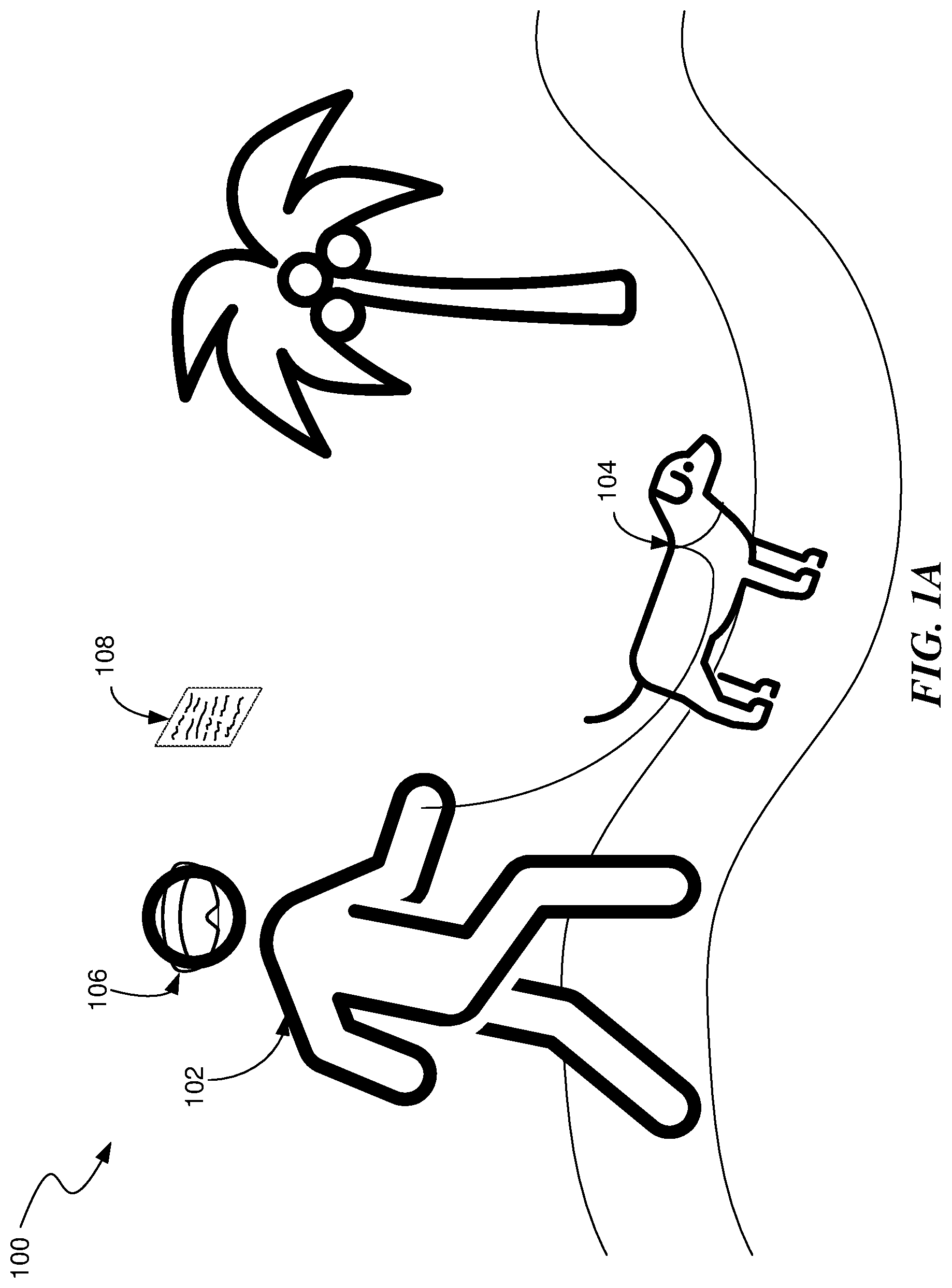
A is a conceptual drawing of a user walking a dog in a mixed reality environment.
B is a conceptual drawing of a user using a pinch gesture to begin recording a voice message.
C is a conceptual drawing of a user using a thumb-swipe gesture to stop recording a message and to send it immediately.
is a flow diagram illustrating a process used in some implementations of the present technology for responding to gestural input.
is a block diagram illustrating an overview of devices on which some implementations of the present technology can operate.
A is a wire diagram illustrating a virtual reality headset which can be used in some implementations of the present technology.
B is a wire diagram illustrating a mixed reality headset which can be used in some implementations of the present technology.
C is a wire diagram illustrating controllers which, in some implementations, a user can hold in one or both hands to interact with an artificial reality environment.
is a block diagram illustrating an overview of an environment in which some implementations of the present technology can operate.
is a block diagram illustrating components which, in some implementations, can be used in a system employing the disclosed technology.
The techniques introduced here may be better understood by referring to the following Detailed Description in conjunction with the accompanying drawings, in which like reference numerals indicate identical or functionally similar elements.
DETAILED DESCRIPTION
Aspects of the present disclosure are directed to a gesture system and techniques for providing “ultra low friction” (ULF) gestures, e.g., for controlling an artificial reality messaging application. The gesture system can recognize ULF gestures such as a “pinch” and “snap” combination where initially a pinch gesture (i.e., bringing the user's thumb tip and tip or side of another finger together) is mapped to an initial action and a following snap gesture (i.e., sliding the thumb off or along the other finger used in the pinch gesture) is mapped to the most common command performed in the current context following the pinch gesture.
For example, a notification of a calendar event alert may be received by an artificial reality device, which displays it for the user. A pinch gesture on a “map to event location” control can cause the artificial reality device to bring up a map in relation to the calendar evet, e.g., showing a path from the user's current location to the location of the calendar event. The most common response to viewing such a map is enter the location in a GPS routing system, so the snap gesture is mapped to this action of starting the navigation system. When the user makes the snap gesture, the routing system is enabled and begins providing directions to the event. However, the user can have other options, such as an un-pinch gesture to close the map or a tug-right gesture (i.e., holding the pinch gesture but moving it to the right) can open an interface to select a different starting point for navigation.
The gesture system can track user contexts (e.g., current activity, recent actions in the artificial reality environment, etc.) It can then determine which commands are most common following a pinch in various contexts and can set the snap action to the most common action. In some implementations, the gesture system can also set the second most common gesture to the tug right gesture or can identify a common “exit” action which is mapped to the tug right gesture.
In some implementations, the gesture system can provide visual affordances to the user to indicate which gestures will provide what result. For example, a drawing of a pinch gesture can be paired with a label telling what the pinch will do and a drawing of a snap gesture can be paired with a label telling what the snap gesture will do.
A presents a scenario 100 in a “mixed reality” environment. A user 102 is walking a dog 104 in the real world. The user 102 is wearing a head-mounted display (HMD) 106 . (See a discussion of an example HMD in the text accompanying B below.) Through the HMD 106 , the user 102 sees the real world but at the same time may interact with aspects of an XR environment overlaid onto the real-world view. In the particular scenario 100 , the user 102 sees a UI 108 displayed by an XR messaging application. While the user 102 interacts with the XR messaging application via its UI 108 , the user 102 can pay attention to the real world in order to avoid hazards while walking the dog 104 .
In B the user 102 (represented here by his hand 110 ) is alerted by the messaging application to an incoming message (e.g., voice, text, video, etc.) The alert can be text, sound, etc. To avoid having to interact with extensive menus of the messaging application's UI 108 , aspects of the present disclosure allow the user 102 to begin recording a voice response by making a pinch gesture 112 directed at the UI display 108 of the messaging application. A gesture-tracking system in his HMD 106 notes this gesture 112 , interprets it, and sends the interpretation to the messaging application which responds by beginning to record a voice response from the user 102 . The user can know that a following snap gesture (see C ) will send the recording due to the displayed visual affordance 113 .
In C , the user 102 decides that his response message is complete, and he wishes to send it immediately without pausing to edit it. He can indicate this by making a “snap” or “thumb swipe” gesture 114 . The user can know to do this due to the displayed visual affordance 113 , indicating that performing a snap gesture will send the current recording. The messaging application's UI 108 also supports other gestural commands. For example, releasing the pinch 112 (from B ) can stop the recording but does not immediately send the message, allowing for reviewing and editing. A “tug left” gesture can command the gesture system to discard the unsent response message.
is a flow diagram illustrating a process 200 used in some implementations for receiving and responding to gestural input. The process 200 is implemented by a gesture-UI-equipped artificial reality messaging application when a user of that application enters an XR environment by, for example donning her head-mounted display 106 . (See B and accompanying text.)
At block 202 , process 200 receives an event trigger. The event trigger can be any event mapped to an action in response to a pinch gesture, such as an incoming message being received for the current user, a notification to be displayed to the current user, a user command being provided, an application running in the artificial reality environment creating a virtual object in the user's field of view, etc. Messages, for example, of any type of modality can be received. The event trigger can be initiated from various sources such as operating system modules (e.g., an alarm going off, notification of system resources, etc.), user action, third-party applications running on the artificial reality device, or network events being received at the artificial reality device.
While any block can be removed or rearranged in various implementations, block 204 is shown in dashed lines to indicate there are specific instances where block 204 is skipped. At block 204 , process 200 alerts the user in relation to the event triggers, e.g., to the user of the presence of the incoming message. In order to avoid distracting the user and forcing her to focus on a display screen of the messaging application, in some variations, the user is notified by a sound produced in her HMD 106 instead of, or in addition to, a static visual notification. A blinking notification can also notify the user without forcing her to divert her attention away from the real world for too long. In some cases, the alert can include one or more controls that the user can interact with, e.g., with a pinch gesture.
At block 206 , process 200 can receive a pinch gesture, related to the event trigger, via a gesture-tracking system associated with the user's HMD 106 . The gesture can be recognized by a gesture recognition system, e.g., one that ingests one or more of images of the user's hands, IMU data, sensor data from a hand or wrist mounted wearable, etc. For example, a machine learning model may be trained to take images of the user's hand and provide a result of a hand pose defining the location of the user's hand and relationships between parts of the user's hand (e.g., relational values or a 3D model of the user's hand). In some implementations, the user may also or alternatively be wearing a device that measures distances between parts of the user's hand to determine the user's had pose. In yet further implementations, a wearable device may produce electrical signals and read how they flow through a user's wrist to get values representing an internal state of the user's wrist which are used to determine a corresponding pose of the user's hand. The pinch gesture can be in relation to the event trigger by the pinch gesture being directed at (i.e., the user's hand was pointed at) a UI display provided in response to the event trigger. Here, a “pinch” gesture is formed when the user touches the tip of her thumb to the tip of another finger, e.g., her index or middle finger or to the side of that finger (e.g., the place on the user's finger between the tip and the first knuckle). One form of pinch gesture is illustrated in B .
At block 208 , process 200 interprets the pinch as a command in relation to the trigger event. For example, process 200 can interpret a pinch on a “respond” control provided in a message alert as a command to begin recording a voice response message. The recording of block 208 continues as long as the user holds the pinch. In some variations, the user can add to the new message a still photograph or short video taken by the HMD's camera. In other cases, the pinch can be mapped to other actions for a message or for a different event trigger. For example, if the event trigger is a display of a newly discovered virtual object, the pinch can select that new virtual object. As another example, if the event trigger is a user's gaze falling on a target object to select it, causing other controls to appear, the pinch on a give control can activate that control.
At block 210 , process 200 receives another gesture from the user. There are a number of possibilities here as indicated by the decision block 212 . The gesture can be recognized by the gesture recognition system, e.g., one that ingests one or more of images of the user's hands, IMU data, sensor data from a hand or wrist mounted wearable, etc., as discussed above. The gesture recognition system can then map the received data to a gesture, e.g., by applying a machine learning model trained on training data that pairs one or more of these data types with gesture selections. If the recognized gesture is a release of the pinch from block 206 , process 200 can continue to block 216 ; if the gesture is a snap, tug right, or thumb-swipe, process 200 can continue to block 214 ; and if the gesture is a tug left process 200 can continue to block 218 . In other implementations, other gestures can be mapped to the transition between block 212 and one of blocks 214 - 218 .
At block 214 , process 200 has received a “tug right,” “snap,” or “thumb swipe” gesture. A tug right is formed by holding the pinch gesture from block 206 and pulling it to the user's right. A snap or thumb swipe is created starting from a pinch and either sliding the tip of the thumb off the connection between the thumb tip and the other finger tip, e.g., the user has moved, above a threshold speed, the tip of the user's thumb away and to the side from the tip of the other of the other of the user's fingers (i.e., a snap gesture) or sliding the thumb tip along the side of the other finger thumb is in contact with in the pinch e.g., the user has moved the tip of the user's thumb away from the tip of the other of the other of the user's fingers and along a side of that other of the user's fingers. The “tug right,” “snap,” or “thumb swipe” gesture can be mapped to a first action. In some implementations, this can be a default action for the event trigger received at block 202 . In other implementations, the first action can be an action previously determined to be most common (for the current user or for users generally) following the context the pinch was made at block 206 . For example, when the pinch is to record a message reply, the most common action mapped to the “tug right,” “snap,” or “thumb swipe” gesture can be to send the newly recorded response message immediately, when it's been determined that this is the most common action users take following a pinch to record a reply to a message. As another example, when the pinch is to select a minimized virtual object in the artificial reality environment, the determined most common action, and thus the action mapped to the “tug right,” “snap,” or “thumb swipe” gesture, can be to expand the minimized virtual object to a full version. As yet a further example, when the pinch is to select a representation of another person in the area (e.g., a version of their avatar in the area, a picture of them, an item associated with the other person, the person themselves), causing a UI for that person to be displayed, the most common action mapped to the “tug right” “snap,” or “thumb swipe” gesture can be to bring up text, call, or other messaging interface to that person.
At block 218 , process 200 has received a “tug left” gesture. A tug left is formed by holding the pinch gesture from block 206 and pulling it to the user's left. The tug left gesture can be mapped to a second action, e.g., the action either second most common following the context the pinch was made at block 206 or an action designated as a delete, discard, or cancel action for the action taken at block 208 . For example, the tug left gesture for the messaging application can be to delete or discard the recorded message. As another example, the tug left gesture for a pinch that selected a virtual object can be to hide or close the virtual object. As a further example, the tug left gesture for a pinch that selected another person can be to close social media objects associated with that other person.
At block 216 , process 200 has received a pinch release, that is, the user stops holding her thumb tip against her other fingertip. The pinch release gesture can be mapped to a third action, e.g., the action either third most common following the context the pinch was made at block 206 or an action designated as a drill down or take a more complicated action for the action taken at block 208 . For example, for the messaging application, process 200 can respond to the pinch release by entering an editing mode where the user can review, edit, and eventually discard or send the recorded message. To enable editing of the message, the messaging application can, in some variations, support a ULF UI with a few basic gestural commands. For example, after entering the editing mode (possibly by making another pinch gesture while at block 216 ), gestures can be mapped to fast forwarding through the message, reversing, redacting a section, adding an effect, deleting the message entirely, etc. As another example, the pinch release gesture for a pinch that selected a virtual object can be to bring up a set of menus or controls for the selected virtual object. As a further example, the pinch release gesture for a pinch that selected another person can be to pull up a profile or interaction menu for the that other person.
In some implementations, the mapping of the gesture to an action at one or more of blocks 214 - 218 can be based on a context that was recognized when the pinch was made at block 206 . For example, the mapping can define, for each gesture type, at a first level an event trigger, and below that a set of contexts, where process 200 takes the action, for the gesture of block 214 , 216 , or 218 , that matches both the event trigger received at block 202 and the context determined for when the pinch gesture was made at block 206 . For example, different actions can be mapped to the snap gesture, for the message received event trigger, depending on contexts. Contexts can be any discernible state such as where the user is looking, what actions the user is taking (e.g., sitting, walking, driving, watching TV, etc.), who else has been identified to be in the vicinity, what the user is doing (e.g., other gestures) with her other hand, a history or relationship between the current user and a user related to the event trigger (e.g., a sender of the message), a determined user physical or emotional state (e.g., pulse, eye movement, temperature, happy, sad, excited, bored, etc.), time of day, date, weather conditions, where the artificial reality device is geographically, an identified type of event occurring around the artificial reality device, recent actions taken by the current user, etc. These contexts can be determined in various ways such as through images, movement data, and/or audio taken of the surrounding area or of the user and provided to one or more machine learning models trained to identify these types of contexts (e.g., object recognizers, action recognizers, people recognizers, emotion identifiers, etc.), from network data supplied from external sources that specify the current context (e.g., time, date, weather condition), from wireless communications with other devices in the area, from internal sensors (e.g., GPS systems, inertial motion unit (IMU) systems, heat sensors, depth sensors, etc.), etc.
In some variations, process 200 allows a user to use the messaging application's gesture-enabled UI to create a new message rather than only to respond to an existing message. For example, the user can pinch select one of her contacts, and then use specific gestures to indicate that she wishes to create a new message for that contact, to review it, edit it as in block 216 , and ultimately send it. In some variations, hand gestures can accompany voice commands that are interpreted by a natural-language processor and sent to the messaging application.
In some variations, a user can pinch to select a menu of related actions. Then particular gestures are mapped to particular default actions within the menu. If, for example, the user pinch selects an icon notifying her that a new message has arrived, a thumb swipe can be interpreted as the default action of dismissing the notification without discarding the new message.
Embodiments of the disclosed technology may include or be implemented in conjunction with an artificial reality system. Artificial reality or extra reality (XR) is a form of reality that has been adjusted in some manner before presentation to a user, which may include, e.g., virtual reality (VR), augmented reality (AR), mixed reality (MR), hybrid reality, or some combination and/or derivatives thereof. Artificial reality content may include completely generated content or generated content combined with captured content (e.g., real-world photographs). The artificial reality content may include video, audio, haptic feedback, or some combination thereof, any of which may be presented in a single channel or in multiple channels (such as stereo video that produces a three-dimensional effect to the viewer). Additionally, in some embodiments, artificial reality may be associated with applications, products, accessories, services, or some combination thereof, that are, e.g., used to create content in an artificial reality and/or used in (e.g., perform activities in) an artificial reality. The artificial reality system that provides the artificial reality content may be implemented on various platforms, including a head-mounted display (HMD) connected to a host computer system, a standalone HMD, a mobile device or computing system, a “cave” environment or other projection system, or any other hardware platform capable of providing artificial reality content to one or more viewers.
“Virtual reality” or “VR,” as used herein, refers to an immersive experience where a user's visual input is controlled by a computing system. “Augmented reality” or “AR” refers to systems where a user views images of the real world after they have passed through a computing system. For example, a tablet with a camera on the back can capture images of the real world and then display the images on the screen on the opposite side of the tablet from the camera. The tablet can process and adjust or “augment” the images as they pass through the system, such as by adding virtual objects. “Mixed reality” or “MR” refers to systems where light entering a user's eye is partially generated by a computing system and partially composes light reflected off objects in the real world. For example, a MR headset could be shaped as a pair of glasses with a pass-through display, which allows light from the real world to pass through a waveguide that simultaneously emits light from a projector in the MR headset, allowing the MR headset to present virtual objects intermixed with the real objects the user can see. “Artificial reality,” “extra reality,” or “XR,” as used herein, refers to any of VR, AR, MR, or any combination or hybrid thereof.
Previous “gaze to tap” systems require users to divert their attention away from the real world while interacting with XR applications. This could lead to hazardous situations for a user in a mixed reality environment or produce annoying delays while the user switches between XR applications and the real world. The ULF gestural UI systems and methods disclosed herein are expected to overcome these deficiencies in existing systems. Through the simplicity of the gestural interface, a user can fully interact with an XR messaging system while maintaining focus on the real world. There is no analog among previous technologies for this ease of combined user interaction in a mixed reality environment. By allowing users to maintain their focus on the real world, the ULF UI allows users to more fully participate in the benefits of XR systems, and, in consequence, enhances the value of the XR environments and the systems that support them.
Several implementations are discussed below in more detail in reference to the figures. is a block diagram illustrating an overview of devices on which some implementations of the disclosed technology can operate. The devices can comprise hardware components of a computing system 300 that interprets gestural input for a messaging application. In various implementations, computing system 300 can include a single computing device 303 or multiple computing devices (e.g., computing device 301 , computing device 302 , and computing device 303 ) that communicate over wired or wireless channels to distribute processing and share input data. In some implementations, computing system 300 can include a stand-alone headset capable of providing a computer created or augmented experience for a user without the need for external processing or sensors. In other implementations, computing system 300 can include multiple computing devices such as a headset and a core processing component (such as a console, mobile device, or server system) where some processing operations are performed on the headset and others are offloaded to the core processing component. Example headsets are described below in relation to A and 4 B . In some implementations, position and environment data can be gathered only by sensors incorporated in the headset device, while in other implementations one or more of the non-headset computing devices can include sensor components that can track environment or position data.
Computing system 300 can include one or more processor(s) 310 (e.g., central processing units (CPUs), graphical processing units (GPUs), holographic processing units (HPUs), etc.) Processors 310 can be a single processing unit or multiple processing units in a device or distributed across multiple devices (e.g., distributed across two or more of computing devices 301 - 303 ).
Computing system 300 can include one or more input devices 320 that provide input to the processors 310 , notifying them of actions. The actions can be mediated by a hardware controller that interprets the signals received from the input device and communicates the information to the processors 310 using a communication protocol. Each input device 320 can include, for example, a mouse, a keyboard, a touchscreen, a touchpad, a wearable input device (e.g., a haptics glove, a bracelet, a ring, an earring, a necklace, a watch, etc.), a camera (or other light-based input device, e.g., an infrared sensor), a microphone, or other user input devices.
Processors 310 can be coupled to other hardware devices, for example, with the use of an internal or external bus, such as a PCI bus, SCSI bus, or wireless connection. The processors 310 can communicate with a hardware controller for devices, such as for a display 330 . Display 330 can be used to display text and graphics. In some implementations, display 330 includes the input device as part of the display, such as when the input device is a touchscreen or is equipped with an eye direction monitoring system. In some implementations, the display is separate from the input device. Examples of display devices are: an LCD display screen, an LED display screen, a projected, holographic, or augmented reality display (such as a heads-up display device or a head-mounted device), and so on. Other I/O devices 340 can also be coupled to the processor, such as a network chip or card, video chip or card, audio chip or card, USB, firewire or other external device, camera, printer, speakers, CD-ROM drive, DVD drive, disk drive, etc.
In some implementations, input from the I/O devices 340 , such as cameras, depth sensors, IMU sensor, GPS units, LiDAR or other time-of-flights sensors, etc. can be used by the computing system 300 to identify and map the physical environment of the user while tracking the user's location within that environment. This simultaneous localization and mapping (SLAM) system can generate maps (e.g., topologies, girds, etc.) for an area (which may be a room, building, outdoor space, etc.) and/or obtain maps previously generated by computing system 300 or another computing system that had mapped the area. The SLAM system can track the user within the area based on factors such as GPS data, matching identified objects and structures to mapped objects and structures, monitoring acceleration and other position changes, etc.
Computing system 300 can include a communication device capable of communicating wirelessly or wire-based with other local computing devices or a network node. The communication device can communicate with another device or a server through a network using, for example, TCP/IP protocols. Computing system 300 can utilize the communication device to distribute operations across multiple network devices.
The processors 310 can have access to a memory 350 , which can be contained on one of the computing devices of computing system 300 or can be distributed across of the multiple computing devices of computing system 300 or other external devices. A memory includes one or more hardware devices for volatile or non-volatile storage, and can include both read-only and writable memory. For example, a memory can include one or more of random access memory (RAM), various caches, CPU registers, read-only memory (ROM), and writable non-volatile memory, such as flash memory, hard drives, floppy disks, CDs, DVDs, magnetic storage devices, tape drives, and so forth. A memory is not a propagating signal divorced from underlying hardware; a memory is thus non-transitory. Memory 350 can include program memory 360 that stores programs and software, such as an operating system 362 , a gesture-based UI 364 that front-ends a messaging application 366 , and other application programs 368 . Memory 350 can also include data memory 370 that can include, e.g., parameters for interpreting gestures, configuration data, settings, user options or preferences, etc., which can be provided to the program memory 360 or any element of the computing system 300 .
Some implementations can be operational with numerous other computing system environments or configurations. Examples of computing systems, environments, and/or configurations that may be suitable for use with the technology include, but are not limited to, XR headsets, personal computers, server computers, handheld or laptop devices, cellular telephones, wearable electronics, gaming consoles, tablet devices, multiprocessor systems, microprocessor-based systems, set-top boxes, programmable consumer electronics, network PCs, minicomputers, mainframe computers, distributed computing environments that include any of the above systems or devices, or the like.
A is a wire diagram of a virtual reality head-mounted display (HMD) 400 , in accordance with some embodiments. The HMD 400 includes a front rigid body 405 and a band 410 . The front rigid body 405 includes one or more electronic display elements of an electronic display 445 , an inertial motion unit (IMU) 415 , one or more position sensors 420 , locators 425 , and one or more compute units 430 . The position sensors 420 , the IMU 415 , and compute units 430 may be internal to the HMD 400 and may not be visible to the user. In various implementations, the IMU 415 , position sensors 420 , and locators 425 can track movement and location of the HMD 400 in the real world and in an artificial reality environment in three degrees of freedom (3DoF) or six degrees of freedom (6DoF). For example, the locators 425 can emit infrared light beams which create light points on real objects around the HMD 400 . As another example, the IMU 415 can include e.g., one or more accelerometers, gyroscopes, magnetometers, other non-camera-based position, force, or orientation sensors, or combinations thereof. One or more cameras (not shown) integrated with the HMD 400 can detect the light points. Compute units 430 in the HMD 400 can use the detected light points to extrapolate position and movement of the HMD 400 as well as to identify the shape and position of the real objects surrounding the HMD 400 .
The electronic display 445 can be integrated with the front rigid body 405 and can provide image light to a user as dictated by the compute units 430 . In various embodiments, the electronic display 445 can be a single electronic display or multiple electronic displays (e.g., a display for each user eye). Examples of the electronic display 445 include: a liquid crystal display (LCD), an organic light-emitting diode (OLED) display, an active-matrix organic light-emitting diode display (AMOLED), a display including one or more quantum dot light-emitting diode (QOLED) sub-pixels, a projector unit (e.g., microLED, LASER, etc.), some other display, or some combination thereof.
In some implementations, the HMD 400 can be coupled to a core processing component such as a personal computer (PC) (not shown) and/or one or more external sensors (not shown). The external sensors can monitor the HMD 400 (e.g., via light emitted from the HMD 400 ) which the PC can use, in combination with output from the IMU 415 and position sensors 420 , to determine the location and movement of the HMD 400 .
B is a wire diagram of a mixed reality HMD system 450 which includes a mixed reality HMD 452 and a core processing component 454 . The mixed reality HMD 452 and the core processing component 454 can communicate via a wireless connection (e.g., a 60 GHz link) as indicated by link 456 . In other implementations, the mixed reality system 450 includes a headset only, without an external compute device or includes other wired or wireless connections between the mixed reality HMD 452 and the core processing component 454 . The mixed reality HMD 452 includes a pass-through display 458 and a frame 460 . The frame 460 can house various electronic components (not shown) such as light projectors (e.g., LASERs, LEDs, etc.), cameras, eye-tracking sensors, MEMS components, networking components, etc.
The projectors can be coupled to the pass-through display 458 , e.g., via optical elements, to display media to a user. The optical elements can include one or more waveguide assemblies, reflectors, lenses, mirrors, collimators, gratings, etc., for directing light from the projectors to a user's eye. Image data can be transmitted from the core processing component 454 via link 456 to HMD 452 . Controllers in the HMD 452 can convert the image data into light pulses from the projectors, which can be transmitted via the optical elements as output light to the user's eye. The output light can mix with light that passes through the display 458 , allowing the output light to present virtual objects that appear as if they exist in the real world.
Similarly to the HMD 400 , the HMD system 450 can also include motion and position tracking units, cameras, light sources, etc., which allow the HMD system 450 to, e.g., track itself in 3DoF or 6DoF, track portions of the user (e.g., hands, feet, head, or other body parts), map virtual objects to appear as stationary as the HMD 452 moves, and have virtual objects react to gestures and other real-world objects.
C illustrates controllers 470 (including controller 476 A and 476 B), which, in some implementations, a user can hold in one or both hands to interact with an artificial reality environment presented by the HMD 400 and/or HMD 450 . The controllers 470 can be in communication with the HMDs, either directly or via an external device (e.g., core processing component 454 ). The controllers can have their own IMU units, position sensors, and/or can emit further light points. The HMD 400 or 450 , external sensors, or sensors in the controllers can track these controller light points to determine the controller positions and/or orientations (e.g., to track the controllers in 3DoF or 6DoF). The compute units 430 in the HMD 400 or the core processing component 454 can use this tracking, in combination with IMU and position output, to monitor hand positions and motions of the user. The controllers can also include various buttons (e.g., buttons 472 A-F) and/or joysticks (e.g., joysticks 474 A-B), which a user can actuate to provide input and interact with objects.
In various implementations, the HMD 400 or 450 can also include additional subsystems, such as an eye tracking unit, an audio system, various network components, etc., to monitor indications of user interactions and intentions. For example, in some implementations, instead of or in addition to controllers, one or more cameras included in the HMD 400 or 450 , or from external cameras, can monitor the positions and poses of the user's hands to determine gestures and other hand and body motions. As another example, one or more light sources can illuminate either or both of the user's eyes and the HMD 400 or 450 can use eye-facing cameras to capture a reflection of this light to determine eye position (e.g., based on set of reflections around the user's cornea), modeling the user's eye and determining a gaze direction.
is a block diagram illustrating an overview of an environment 500 in which some implementations of the disclosed technology can operate. Environment 500 can include one or more client computing devices 505 A-D, examples of which can include computing system 100 . In some implementations, some of the client computing devices (e.g., client computing device 505 B) can be the HMD 400 or the HMD system 450 . Client computing devices 505 can operate in a networked environment using logical connections through network 530 to one or more remote computers, such as a server computing device.
In some implementations, server 510 can be an edge server which receives client requests and coordinates fulfillment of those requests through other servers, such as servers 520 A-C. Server computing devices 510 and 520 can comprise computing systems, such as computing system 100 . Though each server computing device 510 and 520 is displayed logically as a single server, server computing devices can each be a distributed computing environment encompassing multiple computing devices located at the same or at geographically disparate physical locations.
Client computing devices 505 and server computing devices 510 and 520 can each act as a server or client to other server/client device(s). Server 510 can connect to a database 515 . Servers 520 A-C can each connect to a corresponding database 525 A-C. As discussed above, each server 510 or 520 can correspond to a group of servers, and each of these servers can share a database or can have their own database. Though databases 515 and 525 are displayed logically as single units, databases 515 and 525 can each be a distributed computing environment encompassing multiple computing devices, can be located within their corresponding server, or can be located at the same or at geographically disparate physical locations.
Network 530 can be a local area network (LAN), a wide area network (WAN), a mesh network, a hybrid network, or other wired or wireless networks. Network 530 may be the Internet or some other public or private network. Client computing devices 505 can be connected to network 530 through a network interface, such as by wired or wireless communication. While the connections between server 510 and servers 520 are shown as separate connections, these connections can be any kind of local, wide area, wired, or wireless network, including network 530 or a separate public or private network.
is a block diagram illustrating components 600 which, in some implementations, can be used in a system employing the disclosed technology. Components 600 can be included in one device of computing system 100 or can be distributed across multiple of the devices of computing system 100 . The components 600 include hardware 610 , mediator 620 , and specialized components 630 . As discussed above, a system implementing the disclosed technology can use various hardware including processing units 612 , working memory 614 , input and output devices 616 (e.g., cameras, displays, IMU units, network connections, etc.), and storage memory 618 . In various implementations, storage memory 618 can be one or more of: local devices, interfaces to remote storage devices, or combinations thereof. For example, storage memory 618 can be one or more hard drives or flash drives accessible through a system bus or can be a cloud storage provider (such as in storage database 515 or 525 ) or other network storage accessible via one or more communications networks. In various implementations, components 600 can be implemented in a client computing device such as client computing devices 505 or on a server computing device, such as server computing device 510 or 520 .
Mediator 620 can include components which mediate resources between hardware 610 and specialized components 630 . For example, mediator 620 can include an operating system, services, drivers, a basic input output system (BIOS), controller circuits, or other hardware or software systems.
Specialized components 630 can include software or hardware configured to perform operations for providing “ultra low friction” (ULF) gestures. Specialized components 630 can include event trigger recognizer 634 , gesture-tracking system 636 , context recognizer 638 , ULF action implementor 640 , and components and APIs which can be used for providing user interfaces, transferring data, and controlling the specialized components, such as interfaces 632 . In some implementations, components 600 can be in a computing system that is distributed across multiple computing devices or can be an interface to a server-based application executing one or more of specialized components 630 . Although depicted as separate components, specialized components 630 may be logical or other nonphysical differentiations of functions and/or may be submodules or code-blocks of one or more applications.
Event trigger recognizer 634 can receive data about the artificial reality environment, internal artificial reality device state, network messages, or other data mapped to an ULF gesture and can provide a signal for the gesture-tracking system 636 to identify whether a corresponding pinch gesture was made. Additional details on recognizing event triggers are provided above with regard to block 202 of .
Gesture-tracking system 636 can take image, IMU, EMG, or other sensor data and determine a corresponding pose (and in some cases position) of one or both of the user's hands. In some implementations, a gesture can comprise a motion, such as moving a thumb, and the gesture-tracking system 636 can determine the user's hand pose as it changes over time to determine if a pre-defined gesture has been performed. Additional details on gesture recognition are provided above with regard to blocks 206 and 210 of .
Context recognizer 638 can identify a context that exists when a user makes a pinch gesture. In some implementations, the mapping of a gesture to an action can be based on a context that was recognized when the pinch was made. For example, the mapping can define, for each gesture type, at a first level an event trigger, and below that a set of contexts, where the system identifies in the mapping, for the gesture made by the user, the action that also matches both the event trigger and the context determined for when the pinch gesture was made (or when event trigger was received or when the subsequent tug, snap, or thumb-swipe gesture was made). For example, different actions can be mapped to the snap gesture, for the message received event trigger, depending on contexts. Contexts can be any discernible state such as where the user is looking, what actions the user is taking (e.g., sitting, walking, driving, watching TV, etc.), who else has been identified to be in the vicinity, what the user is doing (e.g., other gestures) with her other hand, a history or relationship between the current user and a user related to the event trigger (e.g., a sender of the message), a determined user physical or emotional state (e.g., pulse, eye movement, temperature, happy, sad, excited, bored, etc.), time of day, date, weather conditions, where the artificial reality device is geographically, an identified type of event occurring around the artificial reality device, recent actions taken by the current user, etc. These contexts can be determined in various ways such as through images, movement data, and/or audio taken of the surrounding area or of the user and provided to one or more machine learning models trained to identify these types of contexts (e.g., object recognizers, action recognizers, people recognizers, emotion identifiers, etc.), from network data supplied from external sources that specify the current context (e.g., time, date, weather condition), from wireless communications with other devices in the area, from internal sensors (e.g., GPS systems, inertial motion unit (IMU) systems, heat sensors, depth sensors, etc.), etc.
ULF action implementor 640 can take the action determined to be mapped to the event trigger, pinch, and subsequent gesture (and in some cases context). Additional details on taking actions for ULF gestures are provided above with regard to blocks 214 , 216 , and 218 of .
Those skilled in the art will appreciate that the components illustrated in through 6 described above, and portions of the flow diagram, may be altered in a variety of ways. For example, the order of the logic may be rearranged, substeps may be performed in parallel, illustrated logic may be omitted, other logic may be included, etc. In some implementations, one or more of the components described above can execute one or more of the processes also described above.
Reference in this specification to “implementations” (e.g., “some implementations,” “various implementations,” “one implementation,” “an implementation,” etc.) means that a particular feature, structure, or characteristic described in connection with the implementation is included in at least one implementation of the disclosure. The appearances of these phrases in various places in the specification are not necessarily all referring to the same implementation, nor are separate or alternative implementations mutually exclusive of other implementations. Moreover, various features are described which may be exhibited by some implementations and not by others. Similarly, various requirements are described which may be requirements for some implementations but not for other implementations.
As used herein, being above a threshold means that a value for an item under comparison is above a specified other value, that an item under comparison is among a certain specified number of items with the largest value, or that an item under comparison has a value within a specified top percentage value. As used herein, being below a threshold means that a value for an item under comparison is below a specified other value, that an item under comparison is among a certain specified number of items with the smallest value, or that an item under comparison has a value within a specified bottom percentage value. As used herein, being within a threshold means that a value for an item under comparison is between two specified other values, that an item under comparison is among a middle-specified number of items, or that an item under comparison has a value within a middle-specified percentage range. Relative terms, such as high or unimportant, when not otherwise defined, can be understood as assigning a value and determining how that value compares to an established threshold. For example, the phrase “selecting a fast connection” can be understood to mean selecting a connection that has a value assigned corresponding to its connection speed that is above a threshold.
As used herein, the word “or” refers to any possible permutation of a set of items. For example, the phrase “A, B, or C” refers to at least one of A, B, C, or any combination thereof, such as any of: A; B; C; A and B; A and C; B and C; A, B, and C; or multiple of any item such as A and A; B, B, and C; A, A, B, C, and C; etc.
Although the subject matter has been described in language specific to structural features and/or methodological acts, it is to be understood that the subject matter defined in the appended claims is not necessarily limited to the specific features or acts described above. Specific embodiments and implementations have been described herein for purposes of illustration, but various modifications can be made without deviating from the scope of the embodiments and implementations. The specific features and acts described above are disclosed as example forms of implementing the claims that follow. Accordingly, the embodiments and implementations are not limited except as by the appended claims.
Any patents, patent applications, and other references noted above are incorporated herein by reference. Aspects can be modified, if necessary, to employ the systems, functions, and concepts of the various references described above to provide yet further implementations. If statements or subject matter in a document incorporated by reference conflicts with statements or subject matter of this application, then this application shall control.
Figures (10)
Citations
This patent cites (359)
- US5107443
- US5600765
- US6563498
- US6784901
- US6842175
- US7119819
- US7231609
- US7701439
- US7971157
- US8402391
- US8558759
- US8788952
- US8836768
- US8884876
- US8913056
- US8947351
- US9117274
- US9285589
- US9292089
- US9323422
- US9477303
- US9477368
- US9552673
- US9659413
- US9749367
- US9817472
- US9865260
- US9983687
- US9992451
- US10019843
- US10042430
- US10168789
- US10220303
- US10248284
- US10248301
- US10261595
- US10281976
- US10353532
- US10402081
- US10437460
- US10473935
- US10489978
- US10503349
- US10521944
- US10595011
- US10691205
- US10890983
- US10930075
- US10936080
- US10937215
- US11043004
- US11054895
- US11086406
- US11113891
- US11150730
- US11194438
- US11216152
- US11221730
- US11256336
- US11294475
- US11307671
- US11334212
- US11366319
- US11514650
- US11556183
- US11669298
- US11726578
- US12001419
- US2003/0224854
- US2004/0150664
- US2004/0261013
- US2004/0266505
- US2005/0018216
- US2006/0146765
- US2007/0250787
- US2008/0012865
- US2008/0059904
- US2008/0089587
- US2008/0174550
- US2009/0077504
- US2009/0254843
- US2009/0300639
- US2009/0319929
- US2010/0031203
- US2010/0103101
- US2010/0103167
- US2010/0103178
- US2010/0125815
- US2010/0156892
- US2010/0306716
- US2011/0022393
- US2011/0164029
- US2011/0169927
- US2011/0228078
- US2011/0239155
- US2011/0249024
- US2011/0267265
- US2011/0283231
- US2012/0030624
- US2012/0059720
- US2012/0069168
- US2012/0071892
- US2012/0089950
- US2012/0096397
- US2012/0113223
- US2012/0131495
- US2012/0143358
- US2012/0188279
- US2012/0206345
- US2012/0210254
- US2012/0218183
- US2012/0218395
- US2012/0249740
- US2012/0249741
- US2012/0275686
- US2012/0290662
- US2012/0293544
- US2013/0057642
- US2013/0063345
- US2013/0069985
- US2013/0093751
- US2013/0125066
- US2013/0147793
- US2013/0174101
- US2013/0182902
- US2013/0208135
- US2013/0265220
- US2013/0278501
- US2013/0283213
- US2013/0339142
- US2014/0007484
- US2014/0009407
- US2014/0028567
- US2014/0028716
- US2014/0040815
- US2014/0062854
- US2014/0104206
- US2014/0125598
- US2014/0152623
- US2014/0189737
- US2014/0201145
- US2014/0204002
- US2014/0210797
- US2014/0232637
- US2014/0236996
- US2014/0267078
- US2014/0279242
- US2014/0282274
- US2014/0282275
- US2014/0306891
- US2014/0320408
- US2014/0344922
- US2014/0357366
- US2014/0361988
- US2014/0375691
- US2015/0029120
- US2015/0035746
- US2015/0040040
- US2015/0054742
- US2015/0062160
- US2015/0070332
- US2015/0106767
- US2015/0110285
- US2015/0149929
- US2015/0153833
- US2015/0160736
- US2015/0169076
- US2015/0181679
- US2015/0206321
- US2015/0220150
- US2015/0243100
- US2015/0261318
- US2015/0261659
- US2015/0269783
- US2015/0310263
- US2015/0312185
- US2015/0331576
- US2015/0358088
- US2016/0054851
- US2016/0110052
- US2016/0147308
- US2016/0170603
- US2016/0231833
- US2016/0284125
- US2016/0292217
- US2016/0306431
- US2016/0320853
- US2016/0320926
- US2016/0370971
- US2016/0378291
- US2017/0050542
- US2017/0060230
- US2017/0061600
- US2017/0097141
- US2017/0099295
- US2017/0109936
- US2017/0139478
- US2017/0168566
- US2017/0192513
- US2017/0220119
- US2017/0228130
- US2017/0236492
- US2017/0255786
- US2017/0262063
- US2017/0263056
- US2017/0278304
- US2017/0287225
- US2017/0296363
- US2017/0308118
- US2017/0308165
- US2017/0324935
- US2017/0329419
- US2017/0329488
- US2017/0337742
- US2017/0344220
- US2017/0357320
- US2017/0364198
- US2018/0004283
- US2018/0033204
- US2018/0046245
- US2018/0059901
- US2018/0081456
- US2018/0088677
- US2018/0089349
- US2018/0101237
- US2018/0107278
- US2018/0113599
- US2018/0136898
- US2018/0181245
- US2018/0303446
- US2018/0307303
- US2018/0322701
- US2018/0323992
- US2018/0329492
- US2018/0335925
- US2018/0343023
- US2018/0357780
- US2018/0364808
- US2019/0050062
- US2019/0050071
- US2019/0057531
- US2019/0065026
- US2019/0094981
- US2019/0102043
- US2019/0107894
- US2019/0108668
- US2019/0114835
- US2019/0120593
- US2019/0129607
- US2019/0130653
- US2019/0143204
- US2019/0163266
- US2019/0212827
- US2019/0213792
- US2019/0258318
- US2019/0278376
- US2019/0279424
- US2019/0286231
- US2019/0340833
- US2019/0347865
- US2019/0361521
- US2019/0362557
- US2019/0362562
- US2019/0369391
- US2019/0369752
- US2019/0377416
- US2019/0392729
- US2020/0012341
- US2020/0042111
- US2020/0082629
- US2020/0093200
- US2020/0097077
- US2020/0097091
- US2020/0103980
- US2020/0125176
- US2020/0129850
- US2020/0207358
- US2020/0218423
- US2020/0221019
- US2020/0225736
- US2020/0225758
- US2020/0225830
- US2020/0226814
- US2020/0371666
- US2020/0379576
- US2020/0387287
- US2021/0049360
- US2021/0056750
- US2021/0076080
- US2021/0076091
- US2021/0090331
- US2021/0096726
- US2021/0181863
- US2021/0373672
- US2021/0390781
- US2022/0083197
- US2022/0084279
- US2022/0121288
- US2022/0203996
- US2022/0214743
- US2022/0244834
- US2022/0291755
- US2022/0392172
- US2023/0040610
- US2023/0082789
- US2023/0092282
- US2023/0093979
- US2023/0100689
- US2023/0123518
- US2023/0252737
- US2023/0274512
- US2023/0306695
- US2023/0326144
- US2023/0336593
- US2023/0350497
- US2023/0368620
- US2023/0410398
- US2024/0112415
- US2024/0153220
- US2024/0168542
- US2024/0220752
- US2024/0256032
- US2024/0265656
- US2024/0272764
- US2024/0289013
- US2024/0385692
- US2024/0402800
- US2025/0078577
- US2025/0103141
- US2025/0123691
- US2025/0148728
- US2025/0159301
- US2025/0170475
- US2025/0217818
- US2025/0321630
- US2025/0356601
- US102084354
- US102695032
- US3155560
- US3155560
- US4145397
- US4471559
- USH02197946
- US2012168646
- US2014518596
- US2015511043
- US2015100032
- US2016045623
- US2018516399
- US20120136719
- US20170018930
- US201405411
- US201814438
- US2011029986
- US2012092025
- US2015125375
- US2017009707
- US2018198910
- US2018235371