Abstract
An attachment member for a camera is attachable to a pole or a wall surface. The attachment member includes a camera attachment portion to which the camera is attachable, a protruding portion whose one end is connected to the camera attachment portion, and a back plate connected to another end of the protruding portion. The protruding portion has a pair of side wall portions formed from the back plate toward the camera attachment portion, the pair of side wall portions have a through hole that allows at least one belt to be inserted, and the back plate has a plurality of fixing holes that allow a plurality of fixing members to be screwed.
Claims (7)
1 . An attachment member for a camera that is attachable to a pole or a wall surface, the attachment member comprising: a camera attachment portion to which the camera is attachable; a protruding portion whose one end is connected to the camera attachment portion; and a back plate connected to another end of the protruding portion, wherein the protruding portion has a pair of side wall portions formed from the back plate toward the camera attachment portion, the pair of side wall portions have a through hole that allows at least one belt to be inserted, the back plate has a plurality of fixing holes that allow a plurality of fixing members to be screwed, the protruding portion has an upper surface connecting upper ends of the pair of side wall portions, the through hole is opened to an upper end side of each of the pair of side wall portions, and the upper surface is provided with a notch continuous with the through hole.
Show 6 dependent claims
2 . The attachment member for a camera according to claim 1 , wherein the back plate has a recessed portion that comes into contact with a surface of the pole.
3 . The attachment member for a camera according to claim 1 , wherein the protruding portion has a front wall portion connecting the pair of side wall portions, and the front wall portion and the side wall portions are covered with a cover member.
4 . The attachment member for a camera according to claim 3 , wherein the cover member covers the through hole.
5 . The attachment member for a camera according to claim 3 , wherein a gap that allows the belt to be inserted is provided between each of the pair of side wall portions and the cover member.
6 . The attachment member for a camera according to claim 3 , wherein the cover member covers the back plate, and a gap that allows the belt to pass through is provided between a side surface portion of the back plate and the cover member.
7 . The attachment member for a camera according to claim 1 , wherein the pair of side wall portions have an upper side surface and an intermediate side surface, an intermediate upper surface connecting a lower end of the upper side surface and an upper end of the intermediate side surface is provided, the upper end of the intermediate side surface is provided with an intermediate through hole having an opened upper end, and the intermediate upper surface is provided with a notch continuous with an upper end of the intermediate through hole.
Full Description
Show full text →
CROSS-REFERENCE TO RELATED APPLICATIONS
This application is based on and claims priority under 35 USC 119 from Japanese Patent Application No. 2023-058038 filed on Mar. 31, 2023, the contents of which are incorporated herein by reference.
TECHNICAL FIELD
The present disclosure relates to an attachment member for a camera.
BACKGROUND ART
In the related art, a fixing device for a camera or the like has been disclosed. The fixing device for a camera or the like includes a camera accommodation portion holding portion for holding a camera accommodation portion for accommodating a camera or the like, a base portion for holding the camera accommodation portion holding portion, and a fixing portion for holding the base portion. The fixing device for a camera or the like includes a first position adjusting unit for adjusting a relative position between the camera accommodation portion and the camera accommodation portion holding portion, a second position adjusting unit for adjusting a relative position between the camera accommodation portion holding portion and the base portion, and a third position adjusting unit for adjusting a relative position between the base portion and a fixing portion. The first to third position adjusting units independently adjust the relative position. The fixing portion has an attachment hole and can be bound to a trunk or a branch of a tree, or the like by using an attachment belt or the like.
CITATION LIST
Patent Literature
•
• Patent Literature 1: JP2008-83634A
SUMMARY OF INVENTION
However, the fixing device for a camera or the like is not intended to be attached to a wall. Therefore, it is necessary to use different attachment devices for a camera or the like for attachment to a cylindrical tree trunk or pole and attachment to a flat wall or the like.
An object of the present disclosure is to provide an attachment member for a camera, which enables a camera to be attached to different attachment targets such as a wall or a pole. The present disclosure provides an attachment member for a camera that is attachable to a pole or a wall surface. The attachment member includes a camera attachment portion to which the camera is attachable, a protruding portion whose one end is connected to the camera attachment portion, and a back plate connected to another end of the protruding portion. The protruding portion has a pair of side wall portions formed from the back plate toward the camera attachment portion, the pair of side wall portions have a through hole that allows at least one belt to be inserted, and the back plate has a plurality of fixing holes that allow a plurality of fixing members to be screwed.
According to the present disclosure, a camera is enabled to be attached to different attachment targets such as a wall or a pole.
BRIEF DESCRIPTION OF DRAWINGS
is an external perspective view of a surveillance camera during attachment to a pole;
is a back perspective view of an attachment member during attachment to the pole;
is a side view of the attachment member during attachment to the pole;
is a perspective view of a base member during attachment to the pole;
is a cross-sectional view of the attachment member shown in , which is taken along a line A-A;
is a cross-sectional view of the attachment member shown in , which is taken along a line B-B;
is an external perspective view of the surveillance camera during attachment to a wall surface; and
is a perspective view of the base member during attachment to the wall surface.
DESCRIPTION OF EMBODIMENTS
Hereinafter, embodiments in which an attachment member for a camera according to the present disclosure is specifically disclosed will be described in detail with reference to the drawings as appropriate. However, unnecessarily detailed description may be omitted. For example, detailed description of already well-known matters and redundant description of substantially the same configuration may be omitted. This is to avoid unnecessary redundancy of the following description and facilitate understanding of a person skilled in the art. The accompanying drawings and the following description are provided for a person skilled in the art to sufficiently understand the present disclosure, and are not intended to limit the subject matter described in the claims.
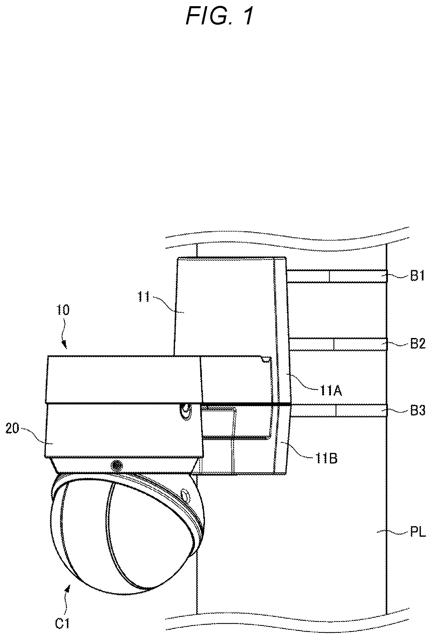
First, a surveillance camera C 1 and an attachment member 10 during attachment to a pole will be described with reference to . is an external perspective view of the surveillance camera C 1 according to an embodiment.
The surveillance camera C 1 (an example of a camera) according to the embodiment is fixed to the attachment member 10 by attaching an attachment portion 20 to attachment holes 17 A, 17 B, and 17 C (see ) of a camera attachment portion 12 C of the attachment member 10 . The surveillance camera C 1 is attached to a pole PL or a wall W that is an attachment target (that is, an installation target) via the attachment member 10 by being attached to the attachment member 10 , and captures an image in an imaging area that is a surveillance target.
The surveillance camera C 1 shown in may be a so-called monocular camera or a compound eye camera. In addition, an external shape of the surveillance camera C 1 shown in is an example, and the external shape thereof is not limited to the example. For example, the surveillance camera C 1 may be a so-called binocular camera in which two camera units (not shown) are arranged in a predetermined direction.
The camera unit referred to herein is an imaging unit for implementing the capture of an image in an imaging area. The camera unit may include a solid-state imaging device such as a charged-coupled device (CCD) or a complementary metal oxide semiconductor (CMOS), and may further include a zoom function, a pan rotation function, or a tilt rotation function.
The attachment member 10 as an example of an attachment member for a camera includes a housing body 11 (an example of a cover member) formed of a resin material, a metal material, or the like, and a base member 12 covered with the housing body 11 . The attachment member 10 is attached to the pole PL, which is an attachment target, by three belts B 1 , B 2 , and B 3 respectively inserted into three sets of through holes 14 A, 15 A, and 16 A described below. Needless to say, the through holes provided in the attachment member 10 are not limited thereto. For example, the attachment member 10 may have at least one set of through holes.
The base member 12 as an example of the attachment member is formed of, for example, a metal material. The base member 12 is integrally formed by connecting a protruding portion 12 A, a coupling portion 12 B, the camera attachment portion 12 C, and a back plate 12 D.
Next, a back structure of the attachment member 10 will be described with reference to . is a back perspective view of the attachment member 10 during attachment to the pole. is a side view of the attachment member 10 during attachment to the pole. The back surface referred to herein is a contact surface that faces an attachment surface of the pole PL or the wall W (see ) which is an attachment target and comes into contact with the pole PL or the wall W by attachment using the belts B 1 to B 3 or screws 32 . In , illustrations of the pole PL and the surveillance camera C 1 are omitted for easy understanding of the description. In , an illustration of the surveillance camera C 1 is omitted for easy understanding of the description.
The attachment member 10 includes the back plate 12 D facing the attachment surface of the pole PL or the wall W (see ) which is an attachment target. The back plate 12 D is formed in a substantially rectangular shape.
The surface of the back plate 12 D facing the attachment surface is not covered with the housing body 11 and is exposed. That is, a side surface (that is, a front surface 12 AF) opposite to the surface facing the attachment surface and an upper side surface 12 AA of the back plate 12 D are covered with the housing body 11 .
In this description, an up-down direction refers to an extension direction of the pole PL, and a left-right direction is a direction perpendicular to the extension direction of the pole PL and parallel to the back plate 12 D. A front-rear direction is a direction perpendicular to the extension direction of the pole PL and perpendicular to the back plate 12 D.
The back plate 12 D includes a pair of recessed portions 13 A and 13 B (see ) and a plurality of screw holes 31 (an example of fixing holes).
The pair of recessed portions 13 A and 13 B are provided at an upper end portion and a lower end portion of the back plate 12 D along the extension direction of the pole PL, respectively. In addition, it is preferable that each of the pair of recessed portions 13 A and 13 B is provided substantially at a center of the back plate 12 D in the left-right direction. Each of the pair of recessed portions 13 A and 13 B has a predetermined curvature and functions as a contact surface that comes into contact with an installation surface (surface) of the pole PL during attachment to the pole.
An opening 21 is formed on a lower surface 12 AG (see ) of the protruding portion 12 A, and allows insertion of a local area network (LAN) cable, a power cable, or the like connected to the surveillance camera C 1 . A position of the opening 21 is not limited to the lower surface 12 AG of the protruding portion 12 A, and may be formed on an upper surface 12 AC.
The belt B 1 is inserted through a pair of through holes 14 A respectively formed in upper side surfaces 12 AA of the protruding portion 12 A. In a state in which the belt B 1 is inserted through the pair of through holes 14 A, both ends of the belt B 1 respectively pass through gaps 18 each formed between the housing body 11 and a respective one of the pair of upper side surfaces 12 AA, and are drawn out in a manner of being attachable to the pole PL (not shown).
The belt B 2 is inserted through a pair of through holes 15 A respectively formed in side surfaces 12 AB of the protruding portion 12 A. In a state in which the belt B 2 is inserted through the pair of through holes 15 A, both ends of the belt B 2 respectively pass through gaps 18 each formed between the housing body 11 and a respective one of the pair of side surfaces 12 AB, and are drawn out in a manner of being attachable to the pole PL (not shown).
The belt B 3 is inserted through a pair of through holes 16 A respectively formed in the side surfaces 12 AB of the protruding portion 12 A. In a state in which the belt B 3 is inserted through the pair of through holes 16 A, both ends of the belt B 3 respectively pass through the gaps 18 formed between the housing body 11 and a respective one of the pair of side surfaces 12 AB, and are drawn out in a manner of being attachable to the pole PL (not shown).
One end portion and the other end portion, which are drawn out, of each of the three belts B 1 to B 3 are connected to each other by a corresponding one of connectors CN 1 , CN 2 , and CN 3 to fix the attachment member 10 to the pole PL in an attachable manner.
As shown in , the back plate 12 D may be provided with notches 30 , through which the belts B 1 to B 3 can be inserted, at six locations corresponding to drawn-out positions at which the three belts B 1 to B 3 are respectively drawn out on both side surfaces in the left-right direction. Accordingly, in the attachment member 10 , even when a diameter of the pole PL is smaller, an installation surface (contact surface) of each of the belts B 1 to B 3 with respect to the pole PL can be larger.
Next, the base member 12 of the attachment member 10 will be described with reference to . is a perspective view of the base member 12 during attachment to the pole. In , illustrations of the surveillance camera C 1 and the housing body 11 are omitted for easy understanding of the description.
The protruding portion 12 A is provided between the coupling portion 12 B and the back plate 12 D, and connects the coupling portion 12 B and the back plate 12 D. The coupling portion 12 B is provided between the protruding portion 12 A and the camera attachment portion 12 C, and connects (couples) the protruding portion 12 A and the camera attachment portion 12 C. The camera attachment portion 12 C is provided continuously with the coupling portion 12 B and is connected to the attachment portion 20 of the surveillance camera C 1 . The back plate 12 D is connected to the protruding portion 12 A.
The protruding portion 12 A includes a pair of upper side surfaces 12 AA and a pair of side surfaces 12 AB (an example of a side wall portion), the upper surface 12 AC, a pair of intermediate upper surfaces 12 AD, a pair of intermediate lower surfaces 12 AE, a pair of lower side surfaces 12 AH, the front surface 12 AF (an example of a front wall portion), and the lower surface 12 AG.
Each of the pair of upper side surfaces 12 AA and the pair of side surfaces 12 AB, the upper surface 12 AC, the pair of intermediate upper surfaces 12 AD, the pair of intermediate lower surfaces 12 AE, the front surface 12 AF, and the lower surface 12 AG is formed on a side opposite to a surface of the back plate 12 D facing the pole PL or the wall W and formed toward a camera attachment portion 12 C side of the back plate 12 D in the front-rear direction.
The pair of upper side surfaces 12 AA and the pair of side surfaces 12 AB are formed at different positions in the left-right direction. The pair of side surfaces 12 AB are closer to the side surfaces of the back plate 12 D in the left-right direction than the pair of upper side surfaces 12 AA. Accordingly, for each of the three sets of through holes 14 A to 16 A, notch portions 14 B to 16 B can be formed in peripheral edge portions on either side in a direction along the extension direction of the pole PL among peripheral edge portions of the through holes 14 A to 16 A.
The upper surface 12 AC is connected to an upper end side of the front surface 12 AF in the up-down direction, and each pair of the pair of upper side surfaces 12 AA and the pair of intermediate upper surfaces 12 AD is connected to the corresponding two ends of the front surface 12 AF in the left-right direction.
One end in the left-right direction of one intermediate upper surface 12 AD is connected to a lower end of one upper side surface 12 AA, and the other end thereof is connected to an upper end of one side surface 12 AB. One end in the front-rear direction of the one intermediate upper surface 12 AD is connected to the back plate 12 D, and the other end thereof is connected to the front surface 12 AF. One end in the left-right direction of the other intermediate upper surface 12 AD (not shown) is connected to a lower end of the other upper side surface 12 AA (not shown), and the other end thereof is connected to the other side surface 12 AB (not shown).
Each of the pair of intermediate lower surfaces 12 AE is a surface facing a respective one of the pair of intermediate upper surfaces 12 AD. The pair of intermediate lower surfaces 12 AE are formed in a manner of extending in the left-right direction. One end in the left-right direction is connected to a lower end of the side surface 12 AB, and the other end is connected to an upper end of the lower side surface 12 AH. The lower ends of the pair of lower side surfaces 12 AH are connected to the lower surface 12 AG formed in a manner of extending in the left-right direction.
The camera attachment portion 12 C has three attachment holes 17 A, 17 B, and 17 C along a circumferential direction. The attachment portion 20 of the surveillance camera C 1 is connected to the three attachment holes 17 A, 17 B, and 17 C so that the surveillance camera C 1 can be attached to the attachment member 10 .
The protruding portion 12 A has a pair of upper side surfaces 12 AA connected to the front surface 12 AF in the left-right direction. In the protruding portion 12 A, one through hole 14 A is provided in each of the pair of upper side surfaces 12 AA connected to the back plate 12 D, and a through hole 15 A and a through hole 16 A are provided in each of the pair of side surfaces 12 AB. Specifically, the belt B 1 is inserted through the pair of through holes 14 A. The belt B 2 is inserted through the pair of through holes 15 A. The belt B 3 is inserted through the pair of through holes 16 A.
The upper surface 12 AC is provided with the notch portions 14 B at one end and the other end thereof in the left-right direction. The notch portion 14 B is continuous with an upper end of the through hole 14 A formed in the upper side surface 12 AA.
Each of the pair of intermediate upper surfaces 12 AD is provided with the notch portion 15 B at an end portion on a side to which the side surface 12 AB is connected in the left-right direction. The notch portion 15 B is continuous with an upper end of the through hole 15 A formed in the side surface 12 AB.
Each of the pair of intermediate lower surfaces 12 AE is provided with the notch portion 16 B at an end portion on a side to which the side surface 12 AB is connected in the left-right direction. The notch portion 16 B is continuous with a lower end of the through hole 16 A formed in the side surface 12 AB.
Accordingly, in the attachment member 10 , the through hole 14 A and the notch portion 14 B are continuous with each other, and the through hole 15 A and the notch portion 15 B are continuous with each other, so that rainwater can be prevented from accumulating on the upper surface 12 AC or the intermediate upper surface 12 AD, and deterioration of the base member 12 due to rust or the like can be more effectively prevented. In the attachment member 10 , the through hole 16 A and the notch portion 16 B are continuous with each other, so that dust or the like is less likely to accumulate on the lower side surface 12 AH.
In addition, in the attachment member 10 , the rainwater easily flows by each of the notch portions 14 B to 16 B, and therefore, it is easy to wash out a salt adhering to each of the belts B 1 to B 3 in an insertion portion of each of the belts B 1 to B 3 into a respective one of the through holes 14 A to 16 A. The attachment member 10 is provided with the intermediate upper surface 12 AD, and therefore, rainwater also easily flows into the notch portion 16 B.
The housing body 11 includes an upper housing body 11 A covering an upper side of the attachment member 10 and a lower housing body 11 B covering a lower side of the attachment member 10 . The upper housing body 11 A has an upper side surface and side surfaces. The lower housing body has side surfaces and a lower side surface.
The upper housing body 11 A covers an upper side surface of the camera attachment portion 12 C, an upper side surface of the coupling portion 12 B, the front surface 12 AF, the upper surface 12 AC, the upper side surfaces 12 AA, the intermediate upper surfaces 12 AD, a portion of the side surface 12 AB above a lower end of a side surface of the coupling portion 12 B and above a lower end of the coupling portion 12 B, and a front surface (surface opposite to the attachment surface) and a side surface of the back plate 12 D located above the lower end of the side surface of the coupling portion 12 B.
The lower housing body 11 B covers a lower side surface of the coupling portion 12 B, a portion of the side surface 12 AB below the lower end of the side surface of the coupling portion 12 B, the intermediate lower surfaces 12 AE, the lower side surfaces 12 AH, the lower surface 12 AG, and the front surface (surface opposite to the attachment surface) and the side surface of the back plate 12 D located below the lower end of the side surface of the coupling portion 12 B.
The opening 21 is provided in a lower surface of the lower housing body 11 B.
The upper housing body 11 A and the lower housing body 11 B have portions overlapping each other on the side surfaces in a combined state. More specifically, a piece extending downward from a lower end of a side surface combined with the lower housing body 11 B is provided in the upper housing body 11 A, and covers an outer side surface of a cut-out portion of an upper end of the lower housing body 11 B.
In the attachment member 10 , normally, the upper side surface of the upper housing body 11 A covers the recessed portion 13 A of the back plate 12 D, and the lower housing body 11 B covers the recessed portion 13 B of the back plate 12 D. Each of them is covered. When the attachment member 10 is attached to the pole, a part of the upper side surface of the upper housing body 11 A covering the recessed portion 13 A and a part of the lower housing body 11 B covering the recessed portion 13 B are cut off by a person who performs the attachment. Accordingly, in the attachment member 10 , each of the pair of recessed portions 13 A and 13 B can abut against the attachment surface of the pole PL.
Next, a drawn-out structure of the belt B 2 will be described with reference to . is a cross-sectional view of the attachment member 10 shown in , which is taken along a line A-A. is a cross-sectional view of the attachment member 10 shown in , which is taken along a line B-B. In the examples shown in , the drawn-out structure of the belt B 2 will be described as an example. The belts B 1 and B 3 are also substantially the same, and thus description thereof will be omitted.
The belt B 2 inserted through the pair of through holes 15 A passes through a gap 18 (an example of a gap) between the housing body 11 and the side surface of the back plate 12 D in the left-right direction, and both ends of the belt B 2 are drawn out of the housing body 11 from an inside of the housing body 11 . The belt B 2 is drawn out in a manner of being attachable to the pole PL (not shown).
Next, the surveillance camera C 1 and the attachment member 10 during attachment to a wall surface will be described with reference to . is an external perspective view of the surveillance camera C 1 during attachment to the wall surface. is a perspective view of the base member 12 during attachment to the wall surface. Note that an illustration of the housing body 11 of the attachment member 10 shown in is omitted for easy understanding of the description.
The back plate 12 D of the base member 12 is a surface facing the wall W, and a surface to be in contact with the wall W is formed as a substantially horizontal surface. In the base member 12 , a plurality of screws 32 (an example of a fixing member) are respectively screwed to a plurality of screw holes 31 provided in the back plate 12 D, so that the back plate 12 D and a wall surface of the wall W come into contact with each other, and the attachment member 10 is attached to the wall W.
As described above, the attachment member 10 (an example of an attachment member of a camera) according to the embodiment can be attached to the pole PL or the wall surface, and includes the camera attachment portion 12 C to which the surveillance camera C 1 (an example of the camera) can be attached, the protruding portion 12 A whose one end side is connected to the camera attachment portion 12 C, and the back plate 12 D connected to the other end of the protruding portion 12 A. The protruding portion 12 A has the pair of upper side surfaces 12 AA (an example of the side wall portion) and the pair of side surfaces 12 AB (an example of the side wall portion) formed from the back plate 12 D toward the camera attachment portion 12 C. The pair of upper side surfaces 12 AA and the pair of side surfaces 12 AB have through holes 14 A to 16 A through which at least one of the belts B 1 to B 3 can be inserted. The back plate 12 D has a plurality of screw holes 31 (an example of fixing holes) into which a plurality of screws 32 (an example of fixing members) can be respectively screwed.
Accordingly, the surveillance camera C 1 can be attached to either one of the pole PL and the wall surface by the attachment member 10 according to the embodiment.
The back plate 12 D of the attachment member 10 according to the embodiment has the recessed portions 13 A and 13 B which can come into contact with a surface of the pole PL. Accordingly, in the attachment member 10 according to the embodiment, when the surveillance camera C 1 is attached to the pole PL, an attachment position of the attachment portion 20 can be determined by bringing the recessed portions 13 A and 13 B into contact with the surface of the pole PL.
The attachment member 10 according to the embodiment has the upper surface 12 AC connecting the upper ends of the pair of upper side surfaces 12 AA. The through hole 14 A is opened to an upper end side of each of the pair of upper side surfaces 12 AA, and the notch 14 B (an example of a notch) continuous with the through hole 14 A is provided in the upper surface 12 AC. Accordingly, in the attachment member 10 according to the embodiment, water droplets such as rainwater is less likely to accumulate on the upper surface 12 AC, and a salt adhering to the belt B 1 is easily washed away with the water droplets. Therefore, in the attachment member 10 , deterioration of the base member 12 due to water droplets and the salt can be more effectively prevented.
The protruding portion 12 A of the attachment member 10 according to the embodiment has the front surface 12 AF (an example of a front wall portion) that connects the pair of upper side surfaces 12 AA and the pair of side surfaces 12 AB. The front surface 12 AF, the upper side surface 12 AA, and the side surfaces 12 AB are covered with the housing body 11 (an example of a cover member). Accordingly, in the attachment member 10 according to the embodiment, ion dust (dust, sand, leaves, or the like) can be more effectively prevented from accumulating on the upper side surface 12 AA and the side surface 12 AB in which the through holes 14 A to 16 A are formed, the upper surface 12 AC, and the intermediate upper surface 12 AD.
In addition, the housing body 11 of the attachment member 10 according to the embodiment covers the through holes 14 A to 16 A. Accordingly, in the attachment member 10 according to the embodiment, dust (dust, sand, leaves, or the like) can be more effectively prevented from accumulating in the through holes 14 A to 16 A.
The gaps 18 (an example of a gap) through which the belts B 1 to B 3 can be respectively inserted are formed between the housing body 11 and the pair of upper side surfaces 12 AA and the pair of side surfaces 12 AB of the attachment member 10 according to the embodiment. Accordingly, in the attachment member 10 according to the embodiment, each of the belts B 1 to B 3 inserted through a respective one of the through holes 14 A to 16 A can be drawn out of the housing body 11 , and attachment to the pole PL by each of the belts B 1 to B 3 can be implemented.
The housing body 11 of the attachment member 10 according to the embodiment covers the back plate 12 D. The gap 18 through which the belts B 1 to B 3 can pass is formed between the side surface of the back plate 12 D and the housing body 11 . Accordingly, the housing body 11 of the attachment member 10 according to the embodiment can be attached to the pole PL.
The pair of side surfaces of the attachment member 10 according to the embodiment include the upper side surfaces 12 AA and the side surfaces 12 AB (an example of the intermediate side surface), and the intermediate upper surface 12 AD connecting the lower end of the upper side surface 12 AA and the upper end of the side surface 12 AB is provided. The through hole 15 A (an example of an intermediate through hole) having an opened upper end is provided at the upper end of the side surface 12 AB. The notch portion 15 B (an example of a notch) continuous with the upper end of the through hole 15 A is formed in the intermediate upper surface 12 AD. Accordingly, in the attachment member 10 according to the embodiment, water droplets such as rainwater are less likely to accumulate on the intermediate upper surface 12 AD, and a salt adhering to the belt B 2 inserted through the through hole 15 A is easily washed away with the water droplets. Therefore, in the attachment member 10 , deterioration of the base member 12 due to water droplets and the salt can be more effectively prevented.
Various embodiments have been described above with reference to the drawings, but the present disclosure is not limited thereto. It is apparent to a person skilled in the art that various changes, modifications, substitutions, additions, deletions, and equivalents can be conceived within the scope of the claims, and it is understood that such modifications also belong to the technical scope of the present disclosure. The respective components in the various embodiments above described may be optionally combined without departing from the gist of the invention.
INDUSTRIAL APPLICABILITY
The present disclosure is useful as an attachment member for a camera, which enables the camera to be attached to different attachment targets such as a wall or a pole.
Figures (8)
Citations
This patent cites (9)
- US4325529
- US8657508
- US9400082
- US2019/0289262
- US2020/0185811
- US114216416
- US102015003008
- US2008-83634
- USWO-2021082559