Optical System, Image Projection Apparatus, and Imaging Apparatus
Abstract
The present disclosure is directed to an optical system internally having an intermediate imaging position that is conjugate to a magnification conjugate point on a magnification side and a reduction conjugate point on a reduction side, respectively, the optical system including: a magnification optical system having a plurality of lens elements, positioned on the magnification side with respect to the intermediate imaging position; and a relay optical system having a plurality of lens elements, positioned on the reduction side with respect to the intermediate imaging position, wherein a first lens element located closest to the magnification side among the plurality of lens elements in magnification optical system is an aspherical lens having a negative power, the optical system satisfies the conditions (1) to (3).
Claims (14)
1 . An optical system internally having an intermediate imaging position at which an intermediate image is formed, the intermediate imaging position being conjugate to a magnification conjugate point on a magnification side and a reduction conjugate point on a reduction side, respectively, the optical system comprising: a magnification optical system having a plurality of lens elements, positioned on the magnification side with respect to the intermediate imaging position; and a relay optical system having a plurality of lens elements, positioned on the reduction side with respect to the intermediate imaging position, wherein a first lens element located closest to the magnification side among the plurality of lens elements in the magnification optical system is an aspherical lens having a negative power, the optical system simultaneously satisfies the following conditions (1) to (3): wherein the plurality of lens elements include a lens element that satisfies both of the conditions (6) and (7) and one lens element that does not satisfy both of the conditions (6) and (7): 0.0055<Δ pgfn< 0.030 (1) 53< vdn< 58 (2) 0.28< fp/fr< 1.0 (3) | ym /( fw ·tan(ω m ))|<3.0 (6) Tg> 300° C. (7) where, Δpgfn=(ngn−nfn)/(nfn−ncn)−(−2.20599×10 −3 ·vdn+6.69612×10 −1 ), vdn is an Abbe number of the first lens element, ngn is a refractive index of the first lens element for a g-line, nfn is a refractive index of the first lens element for an F-line, non is a refractive index of the first lens element for a C-line, fp is a focal length of the magnification optical system, and fr is a focal length of the relay optical system at a wide-angle end, where, fw is a focal length of the entire optical system at the wide-angle end, om is a maximum half angle of view at the wide-angle end, ym is a height at the telephoto end at which the most off-axis main ray passes through a lens surface, and Tg is a glass transition point of lens material.
Show 13 dependent claims
2 . The optical system according to claim 1 , wherein the first lens element has a first lens magnification side aspherical surface facing the magnification side and a first lens reduction side aspherical surface facing the reduction side, and the first lens magnification side aspherical surface and the first lens reduction side aspherical surface satisfies the following condition (8): dZ ( r )/ dr> 0 (8) where, r is a distance (r>0) from a vertex of a surface along a plane perpendicular to an optical axis of the optical system, and Z(r) is an amount of sag of the surface (in case that Z=0 at the vertex (r=0), where Z has a sign + for reduction side displacement with respect to the vertex, and a sign − for magnification side displacement).
3 . The optical system according to claim 1 , satisfying the following condition (9): 0.5<|( L 1 R 1+ L 1 R 2)/( L 1 R 2− L 1 R 1)|<5.0 (9) where, L1R1 is a center curvature radius of a first lens magnification side surface, and L1R2 is a center curvature radius of a first lens reduction side surface.
4 . The optical system according to claim 1 , wherein a second lens element is arranged on the reduction side of the first lens element, and the optical system satisfies the following condition (10): 1.2<| T 1/ fw|< 10.0 (10) where, T1 is an air distance between the first lens element and the second lens element, and fw is a focal length of the entire optical system at the wide-angle end.
5 . The optical system according to claim 1 , satisfying the following condition (11): 10.0<| f 1/ fw|< 16.0 (11) where, f1 is a focal length of the first lens element, and fw is a focal length of the entire optical system at the wide-angle end.
6 . The optical system according to claim 1 , satisfying the following condition (12): −8.0< f 1/ Y max<−1.0 (12) where, f1 is a focal length of the first lens element, and Ymax is a maximum image height.
7 . The optical system according to claim 1 , satisfying the following condition (13): 1.5<| f 1/ fp|< 10.0 (13) where, f1 is a focal length of the first lens element.
8 . The optical system according to claim 1 , satisfying the following condition (14): 1.0<| L 1 R 1/ L 1 R 2|<10.0 (14) where, L1R1 is a center curvature radius of the first lens magnification side surface, and L1R2 is a center curvature radius of the first lens reduction side surface.
9 . The optical system according to claim 1 , satisfying the following condition (15): 0.1 <TL 1/ Y max<5.0 (15) where, TL1 is a center thickness of the first lens element, and Ymax is a maximum image height.
10 . The optical system according to claim 1 , satisfying the following condition (16): 4< L 1 R 1/ Y max<10.5 (16) where, L1R1 is a center curvature radius of the first lens magnification side surface, and Ymax is a maximum image height.
11 . The optical system according to claim 1 , wherein during zooming the magnification optical system is fixed, and a part or all of the plurality of lens elements in the relay optical system is displaced along an optical axis.
12 . An image projection apparatus comprising: the optical system according to claim 1 ; and an image forming element that generates an image to be projected through the optical system onto a screen.
13 . An imaging apparatus comprising: the optical system according to claim 1 ; and an imaging element that receives an optical image formed by the optical system to convert the optical image into an electrical image signal.
14 . The optical system according to claim 1 , satisfying the following conditions (4) and (5): 7<| Ts/fw|< 15 (4) 2<| Tpr/fw|< 7 (5) where, Ts is the longest air distance along an optical axis in the magnification optical system, fw is the focal length of the entire optical system at the wide-angle end, and Tpr is a distance from a surface closest to the magnification side of the magnification optical system rear group to the intermediate imaging position.
Full Description
Show full text →
CROSS-REFERENCE OF RELATED APPLICATIONS
This application is a continuation of International Patent Application No. PCT/JP2020/042917, filed on Nov. 18, 2020, which claims the benefit of Japanese Patent Application No. 2020-013668, filed on Jan. 30, 2020, the contents all of which are incorporated herein by reference.
TECHNICAL FIELD
The present disclosure relates to an optical system that forms an intermediate image. The present disclosure also relates to an image projection apparatus and an imaging apparatus using such an optical system.
BACKGROUND
Intermediate imaging-based optical systems have an advantage of achieving wide-angle projection with a short focal length and a wide screen, while the total length of the optical system tends to be increased, thereby rendering the optical system heavier. When attaching a portion of the optical system to an outside of a hosing of an image projection apparatus body, a moment acting on the center of gravity may cause the optical system to tilt relative to the apparatus body, thereby possibly degrading the optical performance.
In order to reduce a weight of the optical system, it may be conceived that a lens made of a synthetic resin is used in lieu of a lens made of glass. Such a synthetic resin has a smaller specific gravity, a smaller thermal conductivity and a larger coefficient of linear expansion as compared to glass. Thus, the optical system can be lightweight. However if local temperature elevation and thermal deformation take place, some optical aberrations, in particular, chromatic aberration tends to be increased. This tendency is more remarkable in case of high-intensity projection.
Patent Document 1 discloses a wide-angle imaging optical system, wherein the first lens L 1 a positioned closest to the magnification conjugate point has the largest diameter. The first lens L 1 a has aspherical double surfaces with quite complicated shapes, hence, it could be imagined to use a synthetic resin lens. However, such complicated aspherical shapes tend to be sensitive to thermal deformation. Therefore, it is expected that optical aberrations may be significantly degraded due to temperature elevation.
PATENT DOCUMENT
•
• [Patent Document 1] JP 2019-174633 A
SUMMARY
The present disclosure provides an optical system that can reduce a moment acting on the center of gravity and mitigate thermal effect. The present disclosure also provides an image projection apparatus and an imaging apparatus using such an optical system.
One aspect of the present disclosure is directed to an optical system internally having an intermediate imaging position that is conjugate to a magnification conjugate point on a magnification side and a reduction conjugate point on a reduction side, respectively, the optical system comprising:
•
• a magnification optical system having a plurality of lens elements, positioned on the magnification side with respect to the intermediate imaging position; and • a relay optical system having a plurality of lens elements, positioned on the reduction side with respect to the intermediate imaging position, • wherein a first lens element located closest to the magnification side among the plurality of lens elements in magnification optical system is an aspherical lens having a negative power, • the optical system satisfies the following conditions (1) to (3): 0.0055<Δ pgfn< 0.030 (1) 53< vdn< 58 (2) 0.28< fp/fr< 1.0 (3) • where, Δpgfn=(ngn−nfn)/(nfn−ncn)−(−2.20599×10 −3 ·vdn+6.69612×10 −1 ), vdn is an Abbe number of the first lens element, ngn is a refractive index of the first lens element for a g-line, nfn is a refractive index of the first lens element for an F-line, ncn is a refractive index of the first lens element for a C-line, fp is a focal length of the magnification optical system, and fr is a focal length of the relay optical system at a wide-angle end.
Further, an image projection apparatus according to the present disclosure includes the above-described optical system and an image forming element that generates an image to be projected through the optical system onto a screen.
Still further, an imaging apparatus according to the present disclosure includes the above-described optical system and an imaging element that receives an optical image formed by the optical system to convert the optical image into an electrical image signal.
The optical system according to the present disclosure can reduce a moment acting on the center of gravity and mitigate thermal effect. Therefore, even in case of intense light passing through the lens elements, such as, high-intensity projection, the optical performance can be maintained.
BRIEF DESCRIPTION OF THE DRAWINGS
is a layout diagram showing an optical path at a wide-angle end in a zoom lens system of example 1 for an object distance of 1066 mm.
A- 2 C are layout diagrams of the zoom lens system of example 1 for an object distance of 1066 mm.
A- 3 C are longitudinal aberrations diagram of the zoom lens system of example 1 for an object distance of 1066 mm.
is a layout diagram showing an optical path at a wide-angle end in a zoom lens system of example 2 for an object distance of 1066 mm.
A- 5 C are layout diagrams of the zoom lens system of example 2 for an object distance of 1066 mm.
A- 6 C are a longitudinal aberration diagrams of the zoom lens system of example 2 for an object distance of 1066 mm.
is a layout diagram showing an optical path at a wide-angle end in a zoom lens system of example 3 for an object distance of 1066 mm.
A- 8 C are layout diagrams of the zoom lens system of example 3 for an object distance of 1066 mm.
A- 9 C are longitudinal aberration diagrams of the zoom lens system of example 3 for an object distance of 1066 mm.
is a layout diagram showing an optical path at a wide-angle end in a zoom lens system of example 4 for an object distance of 1066 mm.
A- 11 C are layout diagrams of the zoom lens system of example 4 for an object distance of 1066 mm.
A- 12 C are longitudinal aberration diagrams of the zoom lens system of example 4 for an object distance of 1066 mm.
is a layout diagram showing an optical path at a wide-angle end in a zoom lens system of example 5 for an object distance of 1066 mm.
A- 14 C are layout diagrams of the zoom lens system of example 5 for an object distance of 1066 mm.
A- 15 C are longitudinal aberration diagrams of the zoom lens system of example 5 for an object distance of 1066 mm.
is a layout diagram showing an optical path at a wide-angle end in a zoom lens system of example 6 for an object distance of 1066 mm.
A- 17 C are layout diagrams of the zoom lens system of example 6 for an object distance of 1066 mm.
A- 18 C are longitudinal aberration diagrams of the zoom lens system of example 6 for an object distance of 1066 mm.
is a layout diagram showing an optical path at a wide-angle end in a zoom lens system of example 7 for an object distance of 1066 mm.
A- 20 C are layout diagrams of the zoom lens system of example 7 for an object distance of 1066 mm.
A- 21 C are longitudinal aberration diagrams of the zoom lens system of example 7 for an object distance of 1066 mm.
is a block diagram showing an example of an image projection apparatus according to the present disclosure.
is a block diagram showing an example of an imaging apparatus according to the present disclosure.
DESCRIPTION OF EMBODIMENT
Hereinafter, embodiments are described in detail with reference to the drawings as appropriate. However, unnecessarily detailed descriptions may be omitted. For example, detailed descriptions of well-known items or redundant descriptions of substantially the same configurations may be omitted. This is to prevent the following description from being unnecessarily redundant and to facilitate understanding by those skilled in the art.
It should be noted that the applicant provides the accompanying drawings and the following description for those skilled in the art to fully understand the present disclosure, and it is not intended to limit the subject matter described in the claims thereby.
Each example of an optical system according to the present disclosure is described below. In each example, described is an example in which the optical system is used in a projector (an example of an image projection apparatus) that projects onto a screen image light of an original image S obtained by spatially modulating incident light using an image forming element, such as liquid crystal or digital micromirror device (DMD), based on an image signal. In other words, the optical system according to the present disclosure can be used for magnifying the original image S on the image forming element arranged on the reduction side to project the image onto the screen (not shown), which is arranged on an extension line on the magnification side.
Further, the optical system according to the present disclosure can also be used for collecting light emitted from an object located on the extension line on the magnification side to form an optical image of the object on an imaging surface of an imaging element arranged on the reduction side.
First Embodiment
Hereinafter, a first embodiment of the present disclosure is described with reference to to 21 . Here, a zoom lens system is described as an example of the optical system.
, 4 , 7 , 10 , 13 , 16 and 19 are layout diagrams each showing an optical path at a wide-angle end in a zoom lens system according to any of examples 1 to 7 for an object distance of 1066 mm. A- 2 C, 5 A- 5 C, 8 A- 8 C, 11 A- 11 C, 14 A- 14 C, 17 A- 17 C and 20 A- 20 C are layout drawings of the zoom lens system according to examples 1 to 7 for an object distance of 1066 mm. A, 5 A, 8 A, 11 A, 14 A, 17 A and 20 A are lens arrangement diagrams at the wide-angle end in the zoom lens system. B, 5 B, 8 B, 11 B, 14 B, 17 B and 20 B are lens arrangement diagrams at an intermediate position in the zoom lens system. C, 5 C, 8 C, 11 C, 14 C, 17 C and 20 C are lens arrangement diagrams at a telephoto end in the zoom lens system.
The wide-angle end is defined as the shortest focal length state in which the entire optical system has the shortest focal length fw. The intermediate position is defined as an intermediate focal length state between the wide-angle end and the telephoto end. The telephoto end is defined as the longest focal length state in which the entire optical system has the longest focal length ft. By using the focal length fw at the wide-angle end and the focal length ft at the telephoto end, the focal length fm at the intermediate position can be defined as fm=√(fw×ft) (√: square root).
The zoom lens system according to example 1 includes a first lens group G 1 to a fourth lens group G 4 and an optical element P. The first lens group G 1 having a positive power is constituted of a first lens element L 1 to a 15th lens element L 15 , including a surface 1 to a surface 30 (see the numerical examples described later). The second lens group G 2 having a positive power is constituted of a 16th lens element L 16 to a 18th lens element L 18 , including a surface 31 to a surface 36 . The third lens group G 3 having a negative power is constituted of a 19th lens element L 19 to a 22nd lens element L 22 , including a surface 37 to a surface 45 . The fourth lens group G 4 having a positive power is constituted of a 23rd lens element L 23 to a 25th lens element L 25 , including a surface 46 to a surface 51 . The optical element P includes a surface 52 to a surface 53 .
The zoom lens system according to example 2 includes a first lens group G 1 to a fourth lens group G 4 and an optical element P, which is similar to example 1, thus redundant descriptions thereof is omitted.
The zoom lens system according to example 3 includes a first lens group G 1 to a fourth lens group G 4 and an optical element P. The first lens group G 1 having a positive power is constituted of a first lens element L 1 to a 16th lens element L 16 , including a surface 1 to a surface 32 (see the numerical examples described later). The second lens group G 2 having a positive power is constituted of a 17th lens element L 17 to a 19th lens element L 19 , including a surface 33 to a surface 38 . The third lens group G 3 having a negative power is constituted of a 20th lens element L 20 to a 23rd lens element L 23 , including a surface 39 to a surface 47 . The fourth lens group G 4 having a positive power is constituted of a 24th lens element L 24 to a 26th lens element L 26 , including a surface 48 to a surface 53 . The optical element P includes a surface 54 to a surface 55 .
Polygonal line arrows shown between each of A, 5 A, 8 A, 11 A, 14 A, 17 A and 20 A and each of B, 5 B, 8 B, 11 B, 14 B, 17 B and 20 B include straight lines obtained by connecting the positions of the first lens group G 1 to the fourth lens group G 4 corresponding to each of the states of the wide-angle end, the intermediate position, and the telephoto end ranked in order from the top in the drawing. The wide-angle end and the intermediate position, and the intermediate position and the telephoto end are simply connected by a straight line, which is different from the actual movement of each of the lens groups G 1 to G 4 . The symbols (+) and (−) attached to the reference numerals of the respective lens groups G 1 to G 4 indicate the positive or negative power of each of the lens groups G 1 to G 4 .
The zoom lens systems according to examples 1 to 7 may include a focusing adjustment lens group that adjusts the focus when an object distance is changed, and a field curvature correction lens group that corrects the field curvature aberration after focus adjustment by the focusing adjustment lens group.
In each of the drawings, an imaging position on the magnification side (i.e., the magnification conjugate point) is located on the left side, and an imaging position on the reduction side (i.e., the reduction conjugate point) is located on the right side. Further, in each of the drawings, the straight line drawn closest to the reduction side represents a position of the original image S, and an optical element P is located on the magnification side of the original image S. The optical element P represents different optical elements, such as a prism for color separation and color synthesis, an optical filter, a flat-parallel glass plate, a crystal low-pass filter, and an infrared cut filter.
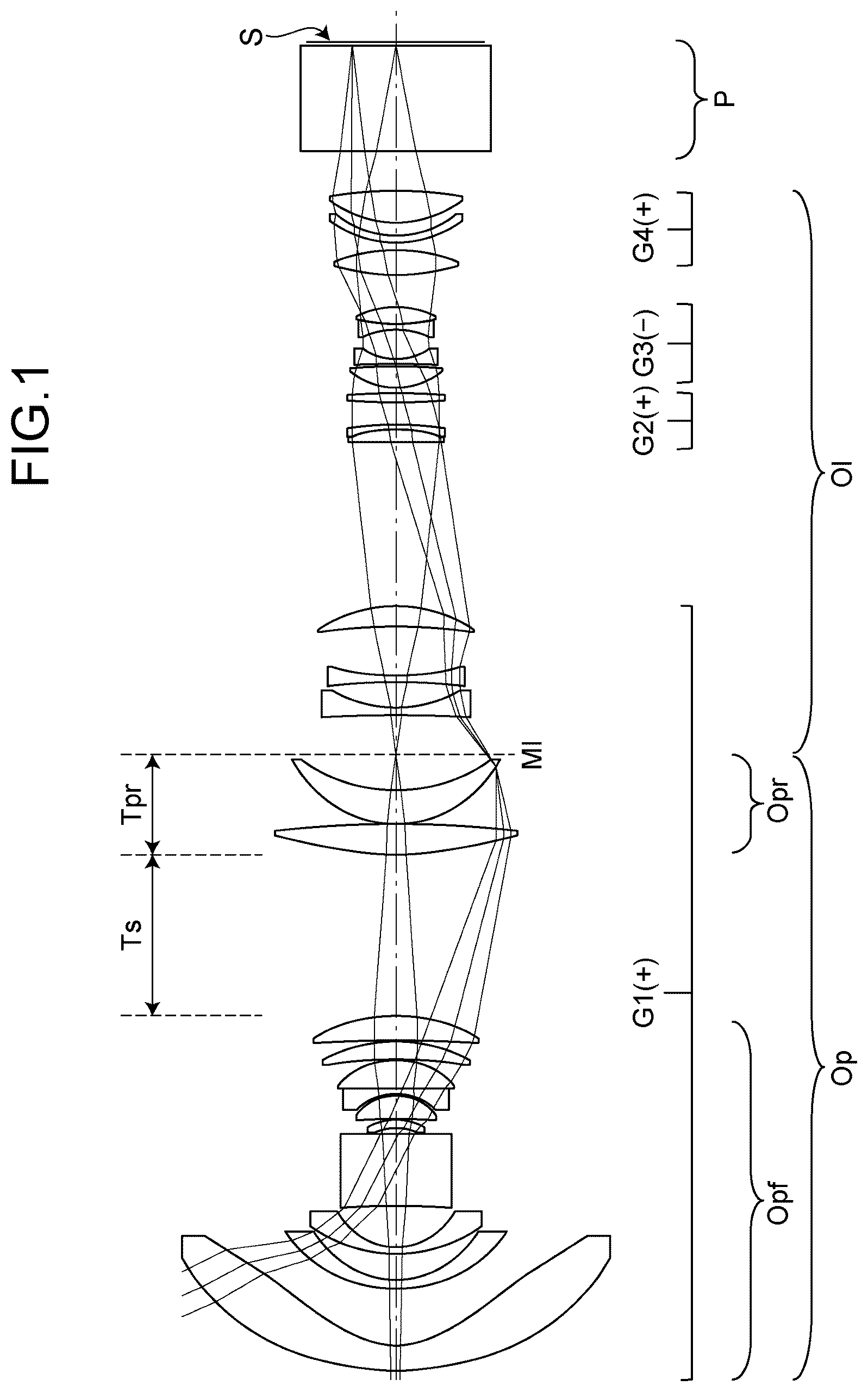
The zoom lens system according to each of examples 1 to 7 internally has an intermediate imaging position MI that is conjugated to the magnification conjugate point on the magnification side and the reduction conjugate point on the reduction side, respectively. Further, in each of the drawings, a magnification optical system Op is positioned on the magnification side with respect to the intermediate imaging position MI, and a relay optical system Ol is positioned on the reduction side with respect to the intermediate imaging position MI.
In the zoom lens system according to each of examples 1 to 7, there are a plurality of air distances among the first lens element L 1 to the 25th lens element L 25 (or 26th lens element L 26 ) and the optical element P. The magnification optical system Op has the longest air distance along an optical axis in the magnification optical system. For example, in examples 1 and 2, as shown in A and 5 A , there is the longest air distance between the 10th lens element L 10 and the 11th lens element L 11 . The magnification optical system Op includes magnification optical system front group Opf positioned on the magnification side with respect to the longest air distance and a magnification optical system rear group Opr positioned on the reduction side with respect to the longest air distance. The front group Opf and the rear group Opr may have a single lens element or plural lens elements.
A- 3 C, 6 A- 6 C, 9 A- 9 C, 12 A- 12 C, 15 A- 15 C, 18 A- 18 C and 21 A- 21 C are longitudinal aberration diagrams of the zoom lens system according to examples 1 to 7 for an object distance of 1066 mm. A, 6 A, 9 A, 12 A, 15 A, 18 A and 21 A show longitudinal aberration diagrams at the wide-angle end of the zoom lens system, and B, 6 B, 9 B, 12 B, 15 B , 18 B and 21 B show longitudinal aberration diagrams at the intermediate position, and 3 C, 6 C, 9 C, 12 C, 15 C, 18 C and 21 C show longitudinal aberration diagrams at the telephoto end.
Each of the longitudinal aberration diagrams shows spherical aberration (SA (mm)), astigmatism (AST (mm)), and distortion (DIS (%)) in order from the left side. In the spherical aberration diagram, the vertical axis represents a pupil height, and a solid line shows the characteristic of the d-line, a short dashed line shows the characteristic of the F-line, and a long dashed line shows the characteristic of the C-line. In the astigmatism diagram, the vertical axis represents an image height, and a solid line shows the characteristic of the sagittal plane (indicated by s in the drawing), and a dashed line shows the characteristic of the meridional plane (indicated by m in the drawing). In the distortion diagram, the vertical axis represents the image height. The distortion represents distortion with respect to equidistant projection.
Example 1
As shown in A- 2 C , the zoom lens system according to example 1 includes the magnification optical system Op and the relay optical system Ol. The magnification optical system Op is constituted of the first lens element L 1 to the 12th lens element L 12 . The magnification optical system Op includes the front group Opf and the rear group Opr.
The front group Opf of the magnification optical system Op is constituted of the first lens element L 1 to the 10th lens element L 10 in order from the magnification side to the reduction side. The first lens element L 1 has a negative meniscus shape with the convex surfaces facing the magnification side. The second lens element L 2 has a negative meniscus shape with the convex surfaces facing the magnification side. The third lens element L 3 has a negative meniscus shape with the convex surfaces facing the magnification side. The fourth lens element L 4 has a biconcave shape. The fifth lens element L 5 has a negative meniscus shape with the convex surfaces facing the reduction side. The sixth lens element L 6 has a positive meniscus shape with the convex surfaces facing the reduction side. The seventh lens element L 7 has a negative meniscus shape with the convex surfaces facing the reduction side. The eighth lens element L 8 has a positive meniscus shape with the convex surfaces facing the reduction side. The ninth lens element L 9 has a positive meniscus shape with the convex surfaces facing the reduction side. The 10th lens element L 10 has a positive meniscus shape with the convex surfaces facing the reduction side.
The rear group Opr of the magnification optical system Op is constituted of the 11th lens element L 11 to the 12th lens element L 12 in this order from the magnification side to the reduction side. The 11th lens element L 11 has a biconvex shape. The 12th lens element L 12 has a positive meniscus shape with the convex surfaces facing the magnification side.
The relay optical system Ol is constituted of the 13th lens element L 13 to the 25th lens element L 25 in order from the magnification side to the reduction side. The 13th lens element L 13 has a biconcave shape. The 14th lens element L 14 has a biconcave shape. The 15th lens element L 15 has a positive meniscus shape with the convex surfaces facing the reduction side. The 16th lens element L 16 has a biconvex shape. The 17th lens element L 17 has a negative meniscus shape with the convex surfaces facing the reduction side. The 18th lens element L 18 has a biconvex shape. The 19th lens element L 19 has a biconvex shape. The 20th lens element L 20 has a biconcave shape. The 21st lens element L 21 has a biconcave shape. The 22nd lens element L 22 has a biconvex shape. The 23rd lens element L 23 has a biconvex shape. The 24th lens element L 24 has a negative meniscus shape with the convex surfaces facing the magnification side. The 25th lens element L 25 has a biconvex shape.
The relay optical system Ol is constituted of the first lens group (L 13 to L 15 ) having a negative power, the second lens group (L 16 to L 18 ) having a positive power, the third lens group (L 19 to L 22 ) having a negative power, and the fourth lens group (L 23 to L 25 ) having a positive power in order from the magnification side to the reduction side. During zooming the first lens group and the third lens group are fixed, and the second lens group and the fourth lens group are displaced along the optical axis.
By way of example, the first lens element L 1 corresponds to the first lens element recited in claims.
The intermediate imaging position MI is located between the 12th lens element L 12 and the 13th lens element L 13 . Further, an aperture A is arranged between the 19th lens element L 19 and the 20th lens element L 20 . The optical element P having zero optical power is arranged on the reduction side of the relay optical system Ol.
Example 2
As shown in A- 5 C , the zoom lens system according to example 2 includes the magnification optical system Op and the relay optical system Ol. The magnification optical system Op is constituted of the first lens element L 1 to the 12th lens element L 12 . The magnification optical system Op includes the front group Opf and the rear group Opr.
The front group Opf of the magnification optical system Op is constituted of the first lens element L 1 to the 10th lens element L 10 in order from the magnification side to the reduction side. The first lens element L 1 has a negative meniscus shape with the convex surfaces facing the magnification side. The second lens element L 2 has a negative meniscus shape with the convex surfaces facing the magnification side. The third lens element L 3 has a negative meniscus shape with the convex surfaces facing the magnification side. The fourth lens element L 4 has a biconvex shape. The fifth lens element L 5 has a positive meniscus shape with the convex surfaces facing the reduction side. The sixth lens element L 6 has a positive meniscus shape with the convex surfaces facing the reduction side. The seventh lens element L 7 has a negative meniscus shape with the convex surfaces facing the reduction side. The eighth lens element L 8 has a positive meniscus shape with the convex surfaces facing the reduction side. The ninth lens element L 9 has a positive meniscus shape with the convex surfaces facing the reduction side. The 10th lens element L 10 has a biconvex shape.
The rear group Opr of the magnification optical system Op is constituted of the 11th lens element L 11 to the 12th lens element L 12 in this order from the magnification side to the reduction side. The 11th lens element L 11 has a biconvex shape. The 12th lens element L 12 has a positive meniscus shape with the convex surfaces facing the magnification side.
The relay optical system Ol is constituted of the 13th lens element L 13 to the 25th lens element L 25 in order from the magnification side to the reduction side. The 13th lens element L 13 has a biconcave shape. The 14th lens element L 14 has a biconcave shape. The 15th lens element L 15 has a biconvex shape. The 16th lens element L 16 has a biconvex shape. The 17th lens element L 17 has a biconcave shape. The 18th lens element L 18 has a biconvex shape. The 19th lens element L 19 has a positive meniscus shape with the convex surfaces facing the magnification side. The 20th lens element L 20 has a negative meniscus shape with the convex surfaces facing the magnification side. The 21st lens element L 21 has a biconcave shape. The 22nd lens element L 22 has a biconvex shape. The 23rd lens element L 23 has a biconvex shape. The 24th lens element L 24 has a negative meniscus shape with the convex surfaces facing the magnification side. The 25th lens element L 25 has a biconvex shape.
The relay optical system Ol is constituted of the first lens group (L 13 to L 15 ) having a negative power, the second lens group (L 16 to L 18 ) having a positive power, the third lens group (L 19 to L 22 ) having a negative power, and the fourth lens group (L 23 to L 25 ) having a positive power in order from the magnification side to the reduction side. During zooming the first lens group and the third lens group are fixed, and the second lens group and the fourth lens group are displaced along the optical axis.
By way of example, the first lens element L 1 corresponds to the first lens element recited in claims.
The intermediate imaging position MI is located between the 12th lens element L 12 and the 13th lens element L 13 . Further, an aperture A is arranged between the 19th lens element L 19 and the 20th lens element L 20 . The optical element P having zero optical power is arranged on the reduction side of the relay optical system Ol.
Example 3
As shown in A- 8 C , the zoom lens system according to example 3 includes the magnification optical system Op and the relay optical system Ol. The magnification optical system Op is constituted of the first lens element L 1 to the 13th lens element L 13 . The magnification optical system Op includes the front group Opf and the rear group Opr.
The front group Opf of the magnification optical system Op is constituted of the first lens element L 1 to the 11th lens element L 11 in order from the magnification side to the reduction side. The first lens element L 1 has a negative meniscus shape with the convex surfaces facing the magnification side. The second lens element L 2 has a negative meniscus shape with the convex surfaces facing the magnification side. The third lens element L 3 has a negative meniscus shape with the convex surfaces facing the magnification side. The fourth lens element L 4 has a biconcave shape. The fifth lens element L 5 has a biconvex shape. The sixth lens element L 6 has a biconcave shape. The seventh lens element L 7 has a biconvex shape. The eighth lens element L 8 has a negative meniscus shape with the convex surfaces facing the reduction side. The ninth lens element L 9 has a positive meniscus shape with the convex surfaces facing the reduction side. The 10th lens element L 10 has a positive meniscus shape with the convex surfaces facing the reduction side. The 11th lens element L 11 has a biconvex shape.
The rear group Opr of the magnification optical system Op is constituted of the 12th lens element L 12 to the 13th lens element L 13 in this order from the magnification side to the reduction side. The 12th lens element L 12 has a biconvex shape. The 13th lens element L 13 has a positive meniscus shape with the convex surfaces facing the magnification side.
The relay optical system Ol is constituted of the 14th lens element L 14 to the 26th lens element L 26 in order from the magnification side to the reduction side. The 14th lens element L 14 has a biconcave shape. The 15th lens element L 15 has a biconcave shape. The 16th lens element L 16 has a positive meniscus shape with the convex surfaces facing the reduction side. The 17th lens element L 17 has a negative meniscus shape with the convex surfaces facing the magnification side. The 18th lens element L 18 has a biconvex shape. The 19th lens element L 19 has a biconvex shape. The 20th lens element L 20 has a biconvex shape. The 21st lens element L 21 has a biconcave shape. The 22nd lens element L 22 has a biconcave shape. The 23rd lens element L 23 has a biconvex shape. The 24th lens element L 24 has a biconvex shape. The 25th lens element L 25 has a negative meniscus shape with the convex surfaces facing the magnification side. The 26th lens element L 26 has a biconvex shape.
The relay optical system Ol is constituted of the first lens group (L 14 to L 16 ) having a negative power, the second lens group (L 17 to L 19 ) having a positive power, the third lens group (L 20 to L 23 ) having a negative power, and the fourth lens group (L 24 to L 26 ) having a positive power in order from the magnification side to the reduction side. During zooming the first lens group and the third lens group are fixed, and the second lens group and the fourth lens group are displaced along the optical axis.
By way of example, the first lens element L 1 corresponds to the first lens element recited in claims.
The intermediate imaging position MI is located between the 13th lens element L 13 and the 14th lens element L 14 . Further, an aperture A is arranged between the 19th lens element L 19 and the 20th lens element L 20 . The optical element P having zero optical power is arranged on the reduction side of the relay optical system Ol.
Example 4
As shown in A- 11 C , the zoom lens system according to example 4 includes the magnification optical system Op and the relay optical system Ol. The magnification optical system Op is constituted of the first lens element L 1 to the 12th lens element L 12 . The magnification optical system Op includes the front group Opf and the rear group Opr.
The front group Opf of the magnification optical system Op is constituted of the first lens element L 1 to the 10th lens element L 10 in order from the magnification side to the reduction side. The first lens element L 1 has a negative meniscus shape with the convex surfaces facing the magnification side. The second lens element L 2 has a negative meniscus shape with the convex surfaces facing the magnification side. The third lens element L 3 has a negative meniscus shape with the convex surfaces facing the magnification side. The fourth lens element L 4 has a biconvex shape. The fifth lens element L 5 has a positive meniscus shape with the convex surfaces facing the reduction side. The sixth lens element L 6 has a positive meniscus shape with the convex surfaces facing the reduction side. The seventh lens element L 7 has a negative meniscus shape with the convex surfaces facing the reduction side. The eighth lens element L 8 has a positive meniscus shape with the convex surfaces facing the reduction side. The ninth lens element L 9 has a positive meniscus shape with the convex surfaces facing the reduction side. The 10th lens element L 10 has a positive meniscus shape with the convex surfaces facing the reduction side.
The rear group Opr of the magnification optical system Op is constituted of the 11th lens element L 11 to the 12th lens element L 12 in this order from the magnification side to the reduction side. The 11th lens element L 11 has a biconvex shape. The 12th lens element L 12 has a positive meniscus shape with the convex surfaces facing the magnification side.
The relay optical system Ol is constituted of the 13th lens element L 13 to the 25th lens element L 25 in order from the magnification side to the reduction side. The 13th lens element L 13 has a biconcave shape. The 14th lens element L 14 has a biconcave shape. The 15th lens element L 15 has a positive meniscus shape with the convex surfaces facing the reduction side. The 16th lens element L 16 has a positive meniscus shape with the convex surfaces facing the reduction side. The 17th lens element L 17 has a negative meniscus shape with the convex surfaces facing the reduction side. The 18th lens element L 18 has a biconvex shape. The 19th lens element L 19 has a biconvex shape. The 20th lens element L 20 has a biconcave shape. The 21st lens element L 21 has a biconcave shape. The 22nd lens element L 22 has a biconvex shape. The 23rd lens element L 23 has a biconvex shape. The 24th lens element L 24 has a negative meniscus shape with the convex surfaces facing the magnification side. The 25th lens element L 25 has a biconvex shape.
The relay optical system Ol is constituted of the first lens group (L 13 to L 15 ) having a negative power, the second lens group (L 16 to L 18 ) having a positive power, the third lens group (L 19 to L 22 ) having a negative power, and the fourth lens group (L 23 to L 25 ) having a positive power in order from the magnification side to the reduction side. During zooming the first lens group and the third lens group are fixed, and the second lens group and the fourth lens group are displaced along the optical axis.
By way of example, the first lens element L 1 corresponds to the first lens element recited in claims.
The intermediate imaging position MI is located between the 12th lens element L 12 and the 13th lens element L 13 . Further, an aperture A is arranged between the 19th lens element L 19 and the 20th lens element L 20 . The optical element P having zero optical power is arranged on the reduction side of the relay optical system Ol.
Example 5
As shown in A- 14 C , the zoom lens system according to example 5 includes the magnification optical system Op and the relay optical system Ol. The magnification optical system Op is constituted of the first lens element L 1 to the 12th lens element L 12 . The magnification optical system Op includes the front group Opf and the rear group Opr.
The front group Opf of the magnification optical system Op is constituted of the first lens element L 1 to the 10th lens element L 10 in order from the magnification side to the reduction side. The first lens element L 1 has a negative meniscus shape with the convex surfaces facing the magnification side. The second lens element L 2 has a negative meniscus shape with the convex surfaces facing the magnification side. The third lens element L 3 has a negative meniscus shape with the convex surfaces facing the magnification side. The fourth lens element L 4 has a positive meniscus shape with the convex surfaces facing the reduction side. The fifth lens element L 5 has a negative meniscus shape with the convex surfaces facing the reduction side. The sixth lens element L 6 has a positive meniscus shape with the convex surfaces facing the reduction side. The seventh lens element L 7 has a biconcave shape. The eighth lens element L 8 has a biconvex shape. The ninth lens element L 9 has a positive meniscus shape with the convex surfaces facing the reduction side. The 10th lens element L 10 has a biconvex shape.
The rear group Opr of the magnification optical system Op is constituted of the 11th lens element L 11 to the 12th lens element L 12 in this order from the magnification side to the reduction side. The 11th lens element L 11 has a biconvex shape. The 12th lens element L 12 has a positive meniscus shape with the convex surfaces facing the magnification side.
The relay optical system Ol is constituted of the 13th lens element L 13 to the 25th lens element L 25 in order from the magnification side to the reduction side. The 13th lens element L 13 has a negative meniscus shape with the convex surfaces facing the magnification side. The 14th lens element L 14 has a biconcave shape. The 15th lens element L 15 has a positive meniscus shape with the convex surfaces facing the reduction side. The 16th lens element L 16 has a biconvex shape. The 17th lens element L 17 has a negative meniscus shape with the convex surfaces facing the reduction side. The 18th lens element L 18 has a biconvex shape. The 19th lens element L 19 has a biconvex shape. The 20th lens element L 20 has a biconcave shape. The 21st lens element L 21 has a biconcave shape. The 22nd lens element L 22 has a biconvex shape. The 23rd lens element L 23 has a biconvex shape. The 24th lens element L 24 has a negative meniscus shape with the convex surfaces facing the magnification side. The 25th lens element L 25 has a biconvex shape.
The relay optical system Ol is constituted of the first lens group (L 13 to L 15 ) having a negative power, the second lens group (L 16 to L 18 ) having a positive power, the third lens group (L 19 to L 22 ) having a negative power, and the fourth lens group (L 23 to L 25 ) having a positive power in order from the magnification side to the reduction side. During zooming the first lens group and the third lens group are fixed, and the second lens group and the fourth lens group are displaced along the optical axis.
By way of example, the first lens element L 1 corresponds to the first lens element recited in claims.
The intermediate imaging position MI is located between the 12th lens element L 12 and the 13th lens element L 13 . Further, an aperture A is arranged between the 19th lens element L 19 and the 20th lens element L 20 . The optical element P having zero optical power is arranged on the reduction side of the relay optical system Ol.
Example 6
As shown in A- 17 C , the zoom lens system according to example 6 includes the magnification optical system Op and the relay optical system Ol. The magnification optical system Op is constituted of the first lens element L 1 to the 12th lens element L 12 . The magnification optical system Op includes the front group Opf and the rear group Opr.
The front group Opf of the magnification optical system Op is constituted of the first lens element L 1 to the 10th lens element L 10 in order from the magnification side to the reduction side. The first lens element L 1 has a negative meniscus shape with the convex surfaces facing the magnification side. The second lens element L 2 has a negative meniscus shape with the convex surfaces facing the magnification side. The third lens element L 3 has a negative meniscus shape with the convex surfaces facing the magnification side. The fourth lens element L 4 has a negative meniscus shape with the convex surfaces facing the reduction side. The fifth lens element L 5 has a negative meniscus shape with the convex surfaces facing the reduction side. The sixth lens element L 6 has a positive meniscus shape with the convex surfaces facing the reduction side. The seventh lens element L 7 has a negative meniscus shape with the convex surfaces facing the reduction side. The eighth lens element L 8 has a positive meniscus shape with the convex surfaces facing the reduction side. The ninth lens element L 9 has a positive meniscus shape with the convex surfaces facing the reduction side. The 10th lens element L 10 has a biconvex shape.
The rear group Opr of the magnification optical system Op is constituted of the 11th lens element L 11 to the 12th lens element L 12 in this order from the magnification side to the reduction side. The 11th lens element L 11 has a biconvex shape. The 12th lens element L 12 has a positive meniscus shape with the convex surfaces facing the magnification side.
The relay optical system Ol is constituted of the 13th lens element L 13 to the 25th lens element L 25 in order from the magnification side to the reduction side. The 13th lens element L 13 has a biconcave shape. The 14th lens element L 14 has a biconcave shape. The 15th lens element L 15 has a positive meniscus shape with the convex surfaces facing the reduction side. The 16th lens element L 16 has a positive meniscus shape with the convex surfaces facing the reduction side. The 17th lens element L 17 has a negative meniscus shape with the convex surfaces facing the reduction side. The 18th lens element L 18 has a biconvex shape. The 19th lens element L 19 has a biconvex shape. The 20th lens element L 20 has a biconcave shape. The 21st lens element L 21 has a biconcave shape. The 22nd lens element L 22 has a biconvex shape. The 23rd lens element L 23 has a biconvex shape. The 24th lens element L 24 has a negative meniscus shape with the convex surfaces facing the magnification side. The 25th lens element L 25 has a biconvex shape.
The relay optical system Ol is constituted of the first lens group (L 13 to L 15 ) having a negative power, the second lens group (L 16 to L 18 ) having a positive power, the third lens group (L 19 to L 22 ) having a negative power, and the fourth lens group (L 23 to L 25 ) having a positive power in order from the magnification side to the reduction side. During zooming the first lens group and the third lens group are fixed, and the second lens group and the fourth lens group are displaced along the optical axis.
By way of example, the first lens element L 1 corresponds to the first lens element recited in claims.
The intermediate imaging position MI is located between the 12th lens element L 12 and the 13th lens element L 13 . Further, an aperture A is arranged between the 19th lens element L 19 and the 20th lens element L 20 . The optical element P having zero optical power is arranged on the reduction side of the relay optical system Ol.
Example 7
As shown in A- 20 C , the zoom lens system according to example 7 includes the magnification optical system Op and the relay optical system Ol. The magnification optical system Op is constituted of the first lens element L 1 to the 12th lens element L 12 . The magnification optical system Op includes the front group Opf and the rear group Opr.
The front group Opf of the magnification optical system Op is constituted of the first lens element L 1 to the 10th lens element L 10 in order from the magnification side to the reduction side. The first lens element L 1 has a negative meniscus shape with the convex surfaces facing the magnification side. The second lens element L 2 has a negative meniscus shape with the convex surfaces facing the magnification side. The third lens element L 3 has a negative meniscus shape with the convex surfaces facing the magnification side. The fourth lens element L 4 has a negative meniscus shape with the convex surfaces facing the reduction side. The fifth lens element L 5 has a negative meniscus shape with the convex surfaces facing the reduction side. The sixth lens element L 6 has a positive meniscus shape with the convex surfaces facing the reduction side. The seventh lens element L 7 has a biconcave shape. The eighth lens element L 8 has a positive meniscus shape with the convex surfaces facing the reduction side. The ninth lens element L 9 has a positive meniscus shape with the convex surfaces facing the reduction side. The 10th lens element L 10 has a biconvex shape.
The rear group Opr of the magnification optical system Op is constituted of the 11th lens element L 11 to the 12th lens element L 12 in this order from the magnification side to the reduction side. The 11th lens element L 11 has a biconvex shape. The 12th lens element L 12 has a positive meniscus shape with the convex surfaces facing the magnification side.
The relay optical system Ol is constituted of the 13th lens element L 13 to the 25th lens element L 25 in order from the magnification side to the reduction side. The 13th lens element L 13 has a negative meniscus shape with the convex surfaces facing the magnification side. The 14th lens element L 14 has a biconcave shape. The 15th lens element L 15 has a positive meniscus shape with the convex surfaces facing the reduction side. The 16th lens element L 16 has a positive meniscus shape with the convex surfaces facing the reduction side. The 17th lens element L 17 has a negative meniscus shape with the convex surfaces facing the reduction side. The 18th lens element L 18 has a biconvex shape. The 19th lens element L 19 has a biconvex shape. The 20th lens element L 20 has a biconcave shape. The 21st lens element L 21 has a biconcave shape. The 22nd lens element L 22 has a biconvex shape. The 23rd lens element L 23 has a biconvex shape. The 24th lens element L 24 has a negative meniscus shape with the convex surfaces facing the magnification side. The 25th lens element L 25 has a biconvex shape.
The relay optical system Ol is constituted of the first lens group (L 13 to L 15 ) having a negative power, the second lens group (L 16 to L 18 ) having a positive power, the third lens group (L 19 to L 22 ) having a negative power, and the fourth lens group (L 23 to L 25 ) having a positive power in order from the magnification side to the reduction side. During zooming the first lens group and the third lens group are fixed, and the second lens group and the fourth lens group are displaced along the optical axis.
By way of example, the first lens element L 1 corresponds to the first lens element recited in claims.
The intermediate imaging position MI is located between the 12th lens element L 12 and the 13th lens element L 13 . Further, an aperture A is arranged between the 19th lens element L 19 and the 20th lens element L 20 . The optical element P having zero optical power is arranged on the reduction side of the relay optical system Ol.
The zoom lens system according to each of examples 1 to 7 may include not only lens elements having an optical power but also elements having zero or substantially zero optical power, such as mirrors, apertures, masks, cover glasses, filters, prisms, wave plates, and polarizing elements.
Next, conditions which the zoom lens system according to examples 1 to 3 can satisfy are described below. Although a plurality of the conditions are defined for the zoom lens system according to each of the examples, all of these plurality of conditions may be satisfied, or the individual conditions may be satisfied to obtain the corresponding effects.
A zoom lens system according to each of examples 1 to is an optical system internally having an intermediate imaging position that is conjugate to a magnification conjugate point on a magnification side and a reduction conjugate point on a reduction side, respectively, the optical system including:
•
• a magnification optical system having a plurality of lens elements, positioned on the magnification side with respect to the intermediate imaging position; and • a relay optical system having a plurality of lens elements, positioned on the reduction side with respect to the intermediate imaging position, • wherein a first lens element located closest to the magnification side among the plurality of lens elements in magnification optical system is an aspherical lens having a negative power, • the optical system satisfies the following conditions (1) to (3): 0.0055 <Δpgfn< 0.030 (1) 53 <vdn< 58 (2) 0.28< fp/fr <1.0 (3) • where, Δpgfn=(ngn−nfn)/(nfn−ncn)−(−2.20599×10 −3 ·vdn+6.69612×10 −1 ), vdn is an Abbe number of the first lens element, ngn is a refractive index of the first lens element for a g-line, nfn is a refractive index of the first lens element for an F-line, ncn is a refractive index of the first lens element for a C-line, fp is a focal length of the magnification optical system, and fr is a focal length of the relay optical system at the wide-angle end.
The condition (1) is a conditional expression for defining a partial dispersion ratio of the g-line and the F-line of the first lens element. When satisfying the condition (1), the axial chromatic aberration of each wavelength can be satisfactorily suppressed over the entire zoom range from the wide-angle end to the telephoto end. If falling below the lower limit value of the condition (1), the axial chromatic aberration at the wide-angle end is increased. If exceeding the upper limit value of the condition (1), the axial chromatic aberration at the telephoto end is increased.
The condition (2) is a conditional expression for defining the Abbe number of the first lens element. When satisfying the condition (2), the axial chromatic aberration can be satisfactorily suppressed. If falling below the lower limit value of the condition (2), the axial chromatic aberration on the short-wavelength side occurs in an over side and is increased. On the other hand, if exceeding the upper limit value, the axial chromatic aberration on the short-wavelength side occurs in an under side and is increased. In order to satisfy both of the conditions (1) and (2), the first lens element may be made of synthetic resin.
The condition (3) is a conditional expression for defining the relationship between the composite focal lengths of the magnification optical system and the relay optical system. When satisfying this, an optical system having a wide angle and a small lens diameter can be realized. If falling below the lower limit value of the conditional expression (3), the effective diameter of the positive power lens element which is located on the magnification side with respect to the intermediate imaging position and closest to the intermediate imaging position becomes too large, and the lens becomes heavier. On the other hand, if exceeding the upper limit value, the effective diameter of the lens located closest to the magnification side becomes too large, and the lens becomes heavier.
In addition to the conditions (1) to (3), more advantageous effects can be obtained by further satisfying at least one of the following conditions (1A), (2A), and (3A): 0.0060 <Δpgfn< 0.028 (1A) 53.5 <Vd< 57.5 (2A) 0.30< fp/fr <0.95 (3A).
Further, in the zoom lens system according to each of examples 1 to 7, there are a plurality of air distances among the lens elements,
•
• the magnification optical system may include a magnification optical system front group positioned on the magnification side with respect to the longest air distance along an optical axis in the magnification optical system and a magnification optical system rear group positioned on the reduction side with respect to the longest air distance, and • the optical system may satisfy the following conditions (4) and (5): 7<| Ts/fw|< 15 (4) 2<| Tpr/fw|< 7 (5) • where, Ts is the longest air distance, fw is a focal length of the entire optical system at the wide-angle end, and Tpr is a distance from a surface closest to the magnification side of the magnification optical system rear group to the intermediate imaging position.
The condition (4) is a conditional expression for defining the relationship between the longest air distance in the magnification optical system and the focal length of the entire optical system at the wide-angle end. When satisfying the condition (4), the optical system can achieve a wider angle. If falling below the lower limit of the condition (4), the lens of the magnification optical system front group becomes heavier. If exceeding the upper limit of the condition (4), the center of gravity of the entire optical system is moved to the magnification side. The condition (5) is a conditional expression for defining the relationship between the distance between the surface of the magnification optical system rear group on the magnification side to the intermediate imaging position and the focal length of the entire optical system at the wide-angle end. When satisfying the condition (5), the effect of the condition (4) can be exhibited.
In addition to the conditions (4) and (5), more advantageous effects can be obtained by further satisfying at least one of the following conditions (4A) and (5A): 7.2<| Ts/fw|< 12 (4A) 3<| Tpr/fw|< 6.9 (5A).
Further, in the zoom lens system according to each of examples 1 to 7, all the lens elements that satisfy the condition (6) among the plurality of lens elements may satisfy the condition (7), and one lens element among the plurality of lens elements may not satisfy both of the conditions (6) and (7): | ym /( fw ·tan(ω m ))|<3.0 (6) Tg> 300° C. (7)
•
• where, fw is a focal length of the entire optical system at the wide-angle end, ωm is a maximum half angle of view at the wide-angle end, ym is a height at the telephoto end at which the most off-axis main ray passes through a lens surface, and Tg is a glass transition point of lens material.
The condition (6) is a conditional expression for defining the relationship among the height at the telephoto end at which the most off-axis main ray passes through the lens surface, the focal length of the entire optical system at the wide-angle end, and the maximum half angle of view at the wide-angle end. The condition (7) is a conditional expression for defining the glass transition point of the lens material. When both of the conditions (6) and (7) are satisfied, deterioration of the lens can be prevented when high intensity light passes through the lens. Note that ym is calculated as a lower one out of a height of the light passing through the surface on the magnification side and a height of the light passing through the surface on the reduction side of the lens.
Further, in the zoom lens system according to each of examples 1 to 7, the first lens element may have a first lens magnification side aspherical surface facing the magnification side and a first lens reduction side aspherical surface facing the reduction side, and
•
• the first lens magnification side surface and the first lens reduction side surface may satisfy the following condition (8): dZ ( r )/ dr> 0 (8) • where, r is a distance (r>0) from a vertex of a surface along a plane perpendicular to the optical axis of the optical system, and • Z(r) is an amount of sag of the surface (assuming that Z=0 at the vertex (r=0), where Z has a sign + for reduction side displacement with respect to the vertex, and a sign − for magnification side displacement).
The condition (8) is a conditional expression for defining that the first derivative dZ(r)/dr of the amount of sag Z(r) of the surface is positive. When satisfying the condition (8), even when local heat is generated in the first lens element, a change in shape due to thermal expansion take places likewise in both the magnification side surface and the reduction side surface of the first lens element. As a result, the occurrence of field curvature and astigmatism can be suppressed.
Further, the zoom lens system according to each of examples 1 to 7 may satisfy the following condition (9): 0.5<|( L 1 R 1+ L 1 R 2)/( L 1 R 2− L 1 R 1)|<5.0 (9)
•
• where, L1R1 is a center curvature radius of the first lens magnification side surface, and L1R2 is a center curvature radius of the first lens reduction side surface.
The condition (9) is a conditional expression for defining a shaping factor of the first lens element located closest to the magnification side of the magnification optical system. When satisfying the condition (9), the effective diameter of the lens can be reduced while the field curvature and distortion aberration are corrected. If falling below the lower limit value of the condition (9), the field curvature and distortion aberration are not sufficiently corrected. If exceeding the upper limit value, the effective diameter of the lens located closer to the magnification side with respect to the aspherical lens becomes large.
In addition to the condition (9), more advantageous effects can be obtained by further satisfying the following condition (9A): 0.8<|( L 1 R 1+ L 1 R 2)/( L 1 R 2− L 1 R 1)|<4.7 (9A)
Further, in the zoom lens system according to each of examples 1 to 7, a second lens element is arranged on the reduction side of the first lens element, and the optical system may satisfy the following condition (10): 1.2<| T 1/ fw|< 10.0 (10)
•
• where, T1 is an air distance between the first lens element and the second lens element, and fw is a focal length of the entire optical system at the wide-angle end.
The condition (10) is a conditional expression for defining the relationship between the air distance between the first lens element and the second lens element and the focal length of the entire optical system at the wide-angle end. When satisfying the condition (10), a lens system having a wide angle and a small lens diameter can be realized. If falling below the lower limit of the condition (10), the air distance between the first lens element and the second lens element becomes too small, and the distortion aberration becomes difficult to be corrected. On the other hand, if exceeding the upper limit of the condition (10), the effective diameter of the first lens element located closest to the magnification side becomes large and heavier.
In addition to the condition (10), more advantageous effects can be obtained by further satisfying the following condition (10A): 1.3<| CT 1/ fw|< 9.5 (10A).
Further, the zoom lens system according to each of examples 1 to 7 may satisfy the following condition (11): 10.0<| f 1/ fw|< 16.0 (11)
•
• where, f1 is a focal length of the first lens element, and fw is a focal length of the entire optical system at the wide-angle end.
The condition (11) is a conditional expression for defining the relationship between the focal length of the first lens element and the focal point of the entire optical system at the wide-angle end. When satisfying the condition (11), a lens system having a wide angle and a small lens diameter can be realized. If falling below the lower limit of the condition (11), the power of the first lens element becomes too weak, and the distortion aberration cannot be appropriately corrected. On the other hand, if exceeding the upper limit of the condition (11), the effective diameter of the first lens element located closest to the magnification side becomes large and heavier.
In addition to the condition (11), more advantageous effects can be obtained by further satisfying the following condition (11A): 10.2<| f 1/ fw|< 15.8 (11A).
Further, the zoom lens system according to each of examples 1 to 7 may satisfy the following condition (12): −8.0< f 1/ Y max<−1.0 (12)
•
• where, f1 is a focal length of the first lens element, and Ymax is a maximum image height.
The condition (12) is a conditional expression for defining the relationship between the focal length of the first lens element and the maximum image height. When satisfying the condition (12), a lens system having a wide angle and a small lens diameter can be realized. If falling below the lower limit of the condition (12), the power of the first lens element becomes too weak, and the distortion aberration cannot be appropriately corrected. On the other hand, if exceeding the upper limit of the condition (12), the effective diameter of the first lens element located on the most magnified side becomes large and heavier.
In addition to the condition (12), more advantageous effects can be obtained by further satisfying the following condition (12A): −7.8< f 1/ Y max<−1.2 (12A).
Further, the zoom lens system according to each of examples 1 to 7 may satisfy the following condition (13): 1.5<| f 1/ fp|< 10.0 (13)
•
• where, f1 is a focal length of the first lens element.
The condition (13) is a conditional expression for defining the relationship between the focal length of the first lens and the focal length of the magnification optical system. When satisfying the condition (13), a lens system having a wide angle and a small lens diameter can be realized. If falling below the lower limit of the condition (13), the distortion aberration cannot be appropriately corrected. On the other hand, if exceeding the upper limit of the condition (13), the effective diameter of the first lens located closest to the magnification side becomes large and heavier.
In addition to the condition (13), more advantageous effects can be obtained by further satisfying the following condition (13A): 2.0<| f 1/ fp|< 9.8 (13A).
Further, the zoom lens system according to each of examples 1 to 7 may satisfy the following condition (14): 1.0<| L 1 R 1/ L 1 R 2|<10.0 (14)
•
• where, L1R1 is a center curvature radius of the first lens magnification side surface, and L1R2 is a center curvature radius of the first lens reduction side surface.
The condition (14) is a conditional expression for defining the relationship between the center curvature radius of the first lens magnification side surface and the center curvature radius of the first lens reduction side surface. If exceeding the upper limit of the condition (14), the difference in curvature is increased, and then the power in the peripheral portion of the lens also is increased, which is effective for the aberration correction but has a large influence on performance when a shape error occurs. If falling below the lower limit of the condition (14), because the refractive power becomes too strong, the aberration correction becomes insufficient.
In addition to the condition (14), more advantageous effects can be obtained by further satisfying the following condition (14A): 1.5<| L 1 R 1/ L 1 R 2|<9.5 (14A).
Further, the zoom lens system according to each of examples 1 to 7 may satisfy the following condition (15): 0.1 <TL 1/ Y max<5.0 (15)
•
• where, TL1 is a center thickness of the first lens element, and Ymax is a maximum image height.
The condition (15) is a conditional expression for defining the relationship between the center thickness of the first lens element and the maximum image height. Usually, as the image height is increased, the lens diameter also is increased. If exceeding the upper limit of the condition (15), the thickness of the lens becomes too large, and the chromatic aberration of magnification tends to occur easily particularly in the peripheral portion of a concave lens. If falling below the lower limit of the condition (15), the strength of the lens becomes insufficient and a shape error tends to occur easily during assembling the lens into a lens barrel or the like, which causes the performance to be deteriorated.
In addition to the condition (15), more advantageous effects can be obtained by further satisfying the following condition (15A): 0.15< TL 1/ Y max<4.7 (15A).
Further, the zoom lens system according to each of examples 1 to 7 may satisfy the following condition (16): 4< L 1 R 1/ Y max<10.5 (16)
•
• where, L1R1 is a center curvature radius of the first lens magnification side surface, and Ymax is a maximum image height.
The condition (16) is a conditional expression for defining the relationship between the center curvature radius of the first lens magnification side surface, and the maximum image height. If exceeding the upper limit of the condition (16), in order to correct the distortion aberration of a barrel shape, the negative refractive power becomes strong near the outermost peripheral portion of the lens, and the lens tends to have an aspherical shape with a large inflection point. If falling below the lower limit of the condition (16), in order to correct the astigmatism of an intermediate image height, the negative refractive power tends to be strong in a region of the lens through which a light ray of the intermediate image height passes, and the lens tends to have an aspherical shape with a large inflection point. Therefore, the processing difficulty of the lens is increased, and the shape error tends to occur easily.
In addition to the condition (16), more advantageous effects can be obtained by further satisfying the following condition (16A): 5.0< L 1 R 1/ Y max<9.6 (16A).
Further, in the zoom lens system according to each of examples 1 to 7, during zooming the magnification optical system may be fixed, and a part or all of the lens elements in the relay optical system may be displaced along the optical axis.
According to this configuration, arrangement of a zoom mechanism closer to the reduction side with respect to the intermediate imaging position allows a zoom operation mechanism, such as, cam, motor, to be implemented on the reduction side. Therefore, the center of gravity of a lens barrel can be brought closer to the reduction side.
As described above, some examples have been described to exemplify the technology disclosed in the present application. The technology of the present disclosure, however, is not limited only to these examples, but also can be applied to other embodiments appropriately devised through modification, substitution, addition, omission and so on.
Hereinafter, numerical examples of the zoom lens system according to examples 1 to 7 are described. In each of the numerical examples, in the table, the unit of length is all “mm”, and the unit of angle of view is all “°” (degree). Further, in each of the numerical examples, r is a radius of curvature, d is a surface interval, nd is a refractive index for d line, and vd is an Abbe number for d line. Further, in each of the numerical examples, a surface marked with “*” is aspherical, and the aspherical shape is defined by the following formula.
Z = h 2 / r 1 + 1 - ( 1 + κ ) ( h / r ) 2 + ∑ A n h n [ Mathematical Formula 1 ]
•
• where, Z is a distance from a point located on an aspherical surface at a height “h” from the optical axis, to the tangent plane of the aspherical vertex, h is a height from the optical axis, r is a radius of curvature of the vertex, κ is a cone constant, and An is a nth-order aspherical coefficient.
Numerical Example 1
Regarding the zoom lens system of numerical example 1 (corresponding to example 1), Table 1 shows surface data, Table 2 shows various data, Table 3 shows single lens data, and Table 4 shows zoom lens group data (unit: mm).
TABLE 1
Surface data
SURFACE NUMBER r d nd vd
Object plane ∞(infinity)
1* 97.69350 10.00000 1.50940 56.5
2* 31.36770 22.18050
3 54.45170 3.50000 1.80420 46.5
4 36.74110 10.22980
5 60.03940 2.50000 1.74330 49.2
6 26.09880 16.03710
7 −348.06090 27.99020 1.59270 35.4
8 1289.14890 2.72020
9* −16.44190 3.13670 1.58699 59.5
10* −17.87810 0.20000
11 −348.97530 9.49740 1.49700 81.6
12 −18.76270 0.20000
13 −23.12320 2.50000 1.86966 20.0
14 −732.20040 0.41780
15 −346.16980 10.45900 1.49700 81.6
16 −31.22520 0.20000
17 −192.12440 7.03440 1.48749 70.2
18 −59.47230 0.20000
19 −876.82590 10.00000 1.49700 81.6
20 −61.25280 63.22670
21 151.52720 11.91050 1.92286 20.9
22 −375.29900 0.20000
23 45.77140 12.92810 1.92286 20.9
24 65.14770 29.26890
25 −367.22620 3.00000 1.77250 49.6
26 50.66420 9.98110
27 −205.48240 2.50000 1.69680 55.5
28 98.55830 19.30500
29 −209.63120 7.75900 1.86966 20.0
30 −55.21680 variable
31 1308.78740 5.01580 1.69680 55.5
32 −53.85000 0.20000
33 −54.57770 1.50000 1.73800 32.3
34 −127.98930 8.99160
35 204.58150 3.58200 1.59282 68.6
36 −192.87060 variable
37 27.84990 8.37540 1.59270 35.4
38 −188.22480 0.20000
39(Aperture) ∞ 0.74080
40 −206.46080 2.00000 1.67300 38.3
41 24.12340 11.45950
42 −31.56750 2.00000 1.67300 38.3
43 64.18200 0.52060
44 80.45210 6.46490 1.43700 95.1
45 −33.71550 variable
46 83.09620 9.68650 1.49700 81.6
47 −63.78080 3.05650
48 45.51150 2.50000 1.62299 58.1
49 37.00910 5.33620
50 44.31030 12.35130 1.43700 95.1
51 −149.35890 variable
52 ∞ 41.75000 1.51680 64.2
53 ∞ BF
Image plane ∞
Aspherical Data 1st Surface
•
• K=0.00000E+00, A3=−7.25014E−06, A4=−1.15220E−06, A5=2.72823E−08, A6=−4.98172E−11, A7=−3.06439E−12, A8=5.81613E−15, A9=4.07487E−16, A10=−2.69504E−18 2nd Surface • K=−1.22715E+00, A3=1.40108E−05, A4=−2.62157E−06, A5=7.38521E−09, A6=2.80400E−10, A7=2.43598E−14, A8=−1.40378E−14, A9=−2.03884E−16, A10=1.80622E−18 9th Surface • K=0.00000E+00, A3=0.00000E+00, A4=2.14919E−05, A5=0.00000E+00, A6=2.07809E−07, A7=0.00000E+00, A8=−7.30054E−10, A9=0.00000E+00, A10=8.85358E−13 10th Surface • K=0.00000E+00, A3=0.00000E+00, A4=2.81203E−05, A5=0.00000E+00, A6=1.62721E−07, A7=0.00000E+00, A8=0.00000E+00, A9=0.00000E+00, A10=0.00000E+00
TABLE 2
Various data
Zoom ratio 1.07128
WIDE- INTER- TELE-
ANGLE MEDIATE PHOTO
Focal length −7.2355 −7.4717 −7.7512
F number −1.91298 −1.91566 −1.91968
Angle of view −66.8135 −66.1719 −65.4059
Image height 17.2650 17.2650 17.2650
Total length 520.0129 520.0218 520.0245
of lens
BF 1.01329 1.02242 1.02517
d30 64.3935 61.5954 58.4105
d36 2.0000 4.7981 7.9829
d45 12.4726 12.3440 12.1423
d51 15.3200 15.4484 15.6501
Position of 42.2840 42.2972 42.3159
entrance pupil
Position of −595.1149 −576.1453 −548.7901
exit pupil
Position of front 34.9607 34.7287 34.4554
principal point
Position of rear 527.2011 527.4432 527.7214
principal point
TABLE 3
Single lens data
Lens element First surface Focal length
1 1 −95.5628
2 3 −154.0331
3 5 −64.1256
4 7 −459.4756
5 9 −1814.3228
6 11 39.5198
7 13 −27.5009
8 15 68.3037
9 17 173.6739
10 19 131.9648
11 21 118.2505
12 23 126.3105
13 25 −57.4536
14 27 −95.2714
15 29 84.2276
16 31 74.3399
17 33 −130.0626
18 35 168.0277
19 37 41.5307
20 40 −31.9830
21 42 −31.1794
22 44 55.3204
23 46 74.2297
24 48 −358.4389
25 50 79.7441
TABLE 4
Zoom lens group data
Position Position
of front of rear
First Focal Total principal principal
Group surface length length point point
1 1 17.89892 299.08240 61.92894 188.87067
2 31 88.42608 19.28940 9.02057 12.67491
3 37 −84.47818 31.76120 30.16528 30.25589
4 46 47.05259 32.93050 10.59383 16.63543
Zoom lens group magnification
First WIDE- INTER- TELE-
Group surface ANGLE MEDIATE PHOTO
1 1 −0.01613 −0.01613 −0.01613
2 31 −1.14821 −1.19150 −1.24493
3 37 −1.26654 −1.24728 −1.21956
4 46 −0.27843 −0.28135 −0.28570
Numerical Example 2
Regarding the zoom lens system of numerical example 2 (corresponding to example 2), Table 5 shows surface data, Table 6 shows various data, Table 7 shows single lens data, and Table 8 shows zoom lens group data (unit: mm).
TABLE 5
Surface data
SURFACE NUMBER r d nd vd
Object plane ∞(infinity)
1* 165.06600 10.00000 1.50940 56.5
2* 37.26640 28.66350
3 59.92230 3.00000 1.83400 37.3
4 30.05740 6.06970
5 40.76120 2.00000 1.80420 46.5
6 23.47790 24.51010
7 169.52580 4.45090 1.49700 81.6
8 −232.47350 2.21550
9* −21.41670 2.48360 1.58699 59.5
10* −21.40060 0.20000
11 −49.10900 7.08080 1.49700 81.6
12 −16.94060 0.20000
13 −22.49620 2.50000 1.86966 20.0
14 −441.93320 0.49480
15 −218.68930 10.07060 1.49700 81.6
16 −27.20590 0.20000
17 −181.89320 7.52360 1.48749 70.2
18 −50.60870 4.98130
19 212.13330 10.00000 1.49700 81.6
20 −103.26610 53.33790
21 89.06370 14.00000 1.80420 46.5
22 −3267.89360 0.20000
23 43.66420 13.03580 1.92286 20.9
24 68.22500 24.37490
25 −126.59430 3.00000 1.77250 49.6
26 46.11280 12.92370
27 −46.42300 2.50000 1.62041 60.3
28 153.22030 14.38260
29 4963.70420 17.00000 1.80420 46.5
30 −51.43220 variable
31 92.95090 6.03150 1.72916 54.7
32 −730.31630 31.25490
33* −31.49100 13.92770 1.58699 59.5
34* 594.70610 0.20000
35 63.95900 10.36090 1.43700 95.1
36 −34.56770 variable
37 29.89280 7.05260 1.59270 35.4
38 1341.86370 0.20000
39(Aperture) ∞ 0.21320
40 757.66530 2.00000 1.65844 50.9
41 25.51370 19.33080
42 −37.71970 2.00000 1.67300 38.3
43 74.95530 0.31620
44 79.99120 8.20600 1.43700 95.1
45 −37.31670 variable
46 63.06970 9.91920 1.49700 81.6
47 −99.17320 0.20000
48 55.94260 2.50000 1.58144 40.7
49 36.03770 4.83460
50 43.09730 14.70570 1.43700 95.1
51 −89.04820 variable
52 ∞ 41.75000 1.51680 64.2
53 ∞ BF
Image plane ∞
Aspherical Data 1st Surface
•
• K=0.00000E+00, A3=−2.65067E−06, A4=4.62668E−07, A5=1.02356E−09, A6=−5.81330E−11, A7=8.20273E−14, A8=6.76604E−15, A9=2.18048E−17, A10=−5.71783E−19 2nd Surface • K=−9.55907E−01, A3=0.00000E+00, A4=−1.80425E−06, A5=0.00000E+00, A6=9.34430E−11, A7=0.00000E+00, A8=9.19265E−15, A9=0.00000E+00, A10=−1.18438E−18 9th Surface • K=0.00000E+00, A3=0.00000E+00, A4=4.18656E−06, A5=0.00000E+00, A6=4.74295E−08, A7=0.00000E+00, A8=−1.07013E−09, A9=0.00000E+00, A10=0.00000E+00 10th Surface • K=0.00000E+00, A3=0.00000E+00, A4=2.35037E−05, A5=0.00000E+00, A6=7.58692E−08, A7=0.00000E+00, A8=−4.25680E−10, A9=0.00000E+00, A10=0.00000E+00 33rd Surface • K=0.00000E+00, A3=0.00000E+00, A4=9.60708E−06, A5=0.00000E+00, A6=−8.51152E−09, A7=0.00000E+00, A8=4.75793E−12, A9=0.00000E+00, A10=0.00000E+00 34th Surface • K=0.00000E+00, A3=0.00000E+00, A4=9.30721E−06, A5=0.00000E+00, A6=−5.66264E−09, A7=0.00000E+00, A8=2.36850E−12, A9=0.00000E+00, A10=0.00000E+00
TABLE 6
Various data
Zoom ratio 1.07524
WIDE- INTER- TELE-
ANGLE MEDIATE PHOTO
Focal length −7.2781 −7.5294 −7.8257
F number −1.89960 −1.90067 −1.90235
Angle of view −66.7419 −66.1476 −65.4354
Image height 17.2650 17.2650 17.2650
Total length 520.0163 520.0156 520.0152
of lens
BF 1.01640 1.01584 1.01552
d30 38.9837 35.3568 31.2138
d36 2.0000 5.6269 9.7698
d45 6.2936 6.2335 6.1191
d51 15.3200 15.3800 15.4944
Position of 40.7256 40.7551 40.7942
entrance pupil
Position of −616.7026 −607.9230 −591.9016
exit pupil
Position of front 33.3618 33.1326 32.8652
principal point
Position of rear 527.2465 527.4938 527.7856
principal point
TABLE 7
Single lens data
Lens element First surface Focal length
1 1 −97.0535
2 3 −75.7737
3 5 −72.5965
4 7 197.9836
5 9 835.3507
6 11 48.4926
7 13 −27.3309
8 15 61.4452
9 17 141.1827
10 19 141.2367
11 21 108.0110
12 23 104.7466
13 25 −43.4262
14 27 −57.1531
15 29 63.3946
16 31 113.4344
17 33 −50.5350
18 35 53.0458
19 37 51.4808
20 40 −40.1428
21 42 −37.0201
22 44 59.4941
23 46 79.1774
24 48 −182.6283
25 50 68.7848
TABLE 8
Zoom lens group data
Position Position
of front of rear
First Focal Total principal principal
Group surface length length point point
1 1 20.36658 281.39930 62.67798 133.51296
2 31 106.43172 61.77500 41.99245 33.45401
3 37 103.98710 39.31880 29.38709 30.25682
4 46 49.83733 32.15950 10.71081 17.31236
Zoom lens group magnification
First WIDE- INTER- TELE-
Group surface ANGLE MEDIATE PHOTO
1 1 −0.01838 −0.01838 −0.01838
2 31 −1.04663 −1.08534 −1.13322
3 37 −1.92102 −1.90368 −1.87104
4 46 −0.17801 −0.17920 −0.18149
Numerical Example 3
Regarding the zoom lens system of numerical example 3 (corresponding to example 3), Table 9 shows surface data, Table 10 shows various data, Table 11 shows single lens data, and Table 12 shows zoom lens group data (unit: mm).
TABLE 9
Surface data
SURFACE NUMBER r d nd vd
Object plane ∞(infinity)
1* 89.99630 8.59390 1.50940 56.5
2* 29.83290 25.73990
3 73.68090 4.00000 1.72916 54.7
4 37.62120 11.07470
5 68.67760 2.50000 1.72916 54.7
6 26.46670 24.87000
7 −82.72950 3.00000 1.48749 70.2
8 193.27580 0.20000
9 55.40140 13.86720 1.49700 81.6
10 −38.61260 0.90070
11 −23.10810 2.99370 1.73800 32.3
12 338.09410 0.20000
13 243.79390 5.98230 1.49700 81.6
14 −22.38130 0.20000
15 −33.81890 2.50000 1.86966 20.0
16 −3046.30550 1.00820
17 −129.36060 6.90580 1.49700 81.6
18 −29.32500 0.20000
19 −157.80220 5.57540 1.72916 54.7
20 −52.92660 0.20000
21 137.68250 9.08670 1.49700 81.6
22 −82.27180 70.03820
23 144.33300 9.45410 1.92286 20.9
24 −743.83350 0.20000
25 46.39800 10.82830 1.92286 20.9
26 67.85260 31.36930
27 −134.17810 3.49510 1.59349 67.0
28 58.02470 26.84610
29 −174.53030 4.00000 1.48749 70.2
30 113.99230 4.75960
31 −224.81500 8.24670 1.86966 20.0
32 −58.15140 variable
33 146.52380 3.00000 1.73800 32.3
34 74.42940 1.69100
35 142.73740 4.65510 1.72916 54.7
36 −204.20580 36.12080
37 255.70130 4.77470 1.59282 68.6
38 −76.13990 variable
39(Aperture) ∞ 0.00000
40 27.70880 8.38830 1.59270 35.4
41 −171.98430 0.20530
42 −246.11820 2.00000 1.65844 50.9
43 23.65710 12.47240
44 −30.41040 2.00000 1.73800 32.3
45 64.94710 0.44100
46 76.95830 6.79230 1.43700 95.1
47 −31.53450 variable
48 78.74410 11.63740 1.49700 81.6
49 −64.61500 0.20000
50 48.33940 2.50000 1.67300 38.3
51 36.05770 3.25360
52 40.85850 14.87760 1.43700 95.1
53 −117.53200 variable
54 ∞ 41.75000 1.51680 64.2
55 ∞ BF
Image plane ∞
Aspherical Data 1st Surface
•
• K=0.00000E+00, A3=−4.98082E−05, A4=1.02415E−06, A5=−2.94689E−08, A6=7.04235E−10, A7=−6.53517E−12, A8=−1.32511E−14, A9=4.97035E−16, A10=−1.16266E−18, A11=1.10076E−22, A12=−1.04222E−23, A13=−7.34121E−26, A14=−1.19521E−26, A15=5.84967E−29, A16=−1.36553E−32, A17=−1.81844E−33, A18=−1.06538E−35, A19=−2.13620E−37, A20=−9.95976E−39 2nd Surface • K=−9.54170E−01, A3=−1.48327E−05, A4=−2.41212E−06, A5=−5.68248E−10, A6=1.08199E−10, A7=−3.03274E−13, A8=3.45630E−15, A9=9.09825E−17, A10=4.23242E−18, A11=−4.76060E−21, A12=−5.81989E−22, A13=−8.46992E−24, A14=8.97671E−26, A15=−4.55046E−28, A16=−3.81800E−30, A17=1.48597E−32, A18=1.41251E−33, A19=3.80980E−35, A20=−4.85676E−37
TABLE 10
Various data
Zoom ratio 1.07159
WIDE- INTER- TELE-
ANGLE MEDIATE PHOTO
Focal length −7.2461 −7.4838 −7.7648
F number −1.97041 −1.97181 −1.97429
Angle of view −66.7864 −66.1701 −65.4248
Image height 17.2650 17.2650 17.2650
Total length 520.0186 520.0315 520.0365
of lens
BF 1.01858 1.03157 1.03656
d32 34.3954 31.8072 28.8643
d38 2.0000 4.5882 7.5311
d47 11.6892 11.6283 11.4986
d53 15.3200 15.3808 15.5105
Position of 41.5035 41.5161 41.5337
entrance pupil
Position of −3602.6235 −3265.6740 −2723.7680
exit pupil
Position of front 34.2428 34.0151 33.7467
principal point
Position of rear 527.2172 527.4647 527.7469
principal point
TABLE 11
Single lens data
Lens element First surface Focal length
1 1 −92.0424
2 3 −110.5981
3 5 −60.5692
4 7 −118.4160
5 9 48.1403
6 11 −29.2058
7 13 41.5565
8 15 −39.3391
9 17 74.5917
10 19 106.8222
11 21 105.0609
12 23 131.6545
13 25 127.9993
14 27 −67.7935
15 29 −140.8095
16 31 88.1681
17 33 −208.6590
18 35 115.8747
19 37 99.4996
20 40 40.9024
21 42 −32.6823
22 44 −27.8176
23 46 52.1803
24 48 73.3900
25 50 −229.6827
26 52 71.4189
TABLE 12
Zoom lens group data
Position Position
of front of rear
First Focal Total principal principal
Group surface length length point point
1 1 16.36167 298.83590 59.39221 196.90868
2 33 80.54203 50.24160 37.19334 37.42587
3 39 −74.04702 32.29930 27.69110 28.51657
4 48 45.95013 32.46860 9.73608 17.61383
Zoom lens group magnification
First WIDE- INTER- TELE-
Group surface ANGLE MEDIATE PHOTO
1 1 −0.01476 −0.01476 −0.01476
2 33 −1.05462 −1.09161 −1.13696
3 39 −1.51335 −1.50134 −1.48004
4 48 −0.27787 −0.27948 −0.28241
Numerical Example 4
Regarding the zoom lens system of numerical example 4 (corresponding to example 4), Table 13 shows surface data, Table 14 shows various data, Table 15 shows single lens data, and Table 16 shows zoom lens group data (unit: mm).
TABLE 13
Surface data
SURFACE NUMBER r d nd vd
Object plane ∞(infinity)
1* 102.89670 10.00000 1.50940 56.5
2* 31.58350 20.90230
3 52.49390 3.50000 1.80420 46.5
4 38.06810 11.11230
5 66.62750 2.50000 1.74330 49.2
6 25.91550 14.61510
7 −476.15420 29.73760 1.59270 35.4
8 1818.52440 2.87470
9* −17.79050 3.51460 1.58699 59.5
10* −18.79510 0.20000
11 −596.56580 10.03480 1.49700 81.6
12 −18.35160 0.20000
13 −21.74040 2.50000 1.86966 20.0
14 −618.61420 0.43790
15 −312.69370 10.55520 1.49700 81.6
16 −31.49520 0.20000
17 −196.16590 7.17640 1.48749 70.2
18 −60.18670 1.95440
19 −346.58290 10.00000 1.49700 81.6
20 −59.55810 54.34820
21 167.48040 12.82620 1.92286 20.9
22 −331.21280 8.17680
23 45.65930 12.99900 1.92286 20.9
24 66.26060 29.76290
25 −248.95030 3.00000 1.77250 49.6
26 54.43690 7.78420
27 −159.54610 2.50000 1.69680 55.5
28 100.51300 17.58570
29 −240.94020 8.61860 1.86966 20.0
30 −53.28050 variable
31 −5306.70620 4.91380 1.69680 55.5
32 −53.10680 0.20000
33 −53.99280 1.50000 1.73800 32.3
34 −111.83480 2.73900
35 150.54590 3.50470 1.59282 68.6
36 −331.21000 variable
37 27.97490 8.32580 1.59270 35.4
38 −188.82190 0.20000
39(Aperture) ∞ 0.73020
40 −210.55990 2.00000 1.67300 38.3
41 24.31650 11.54170
42 −31.47630 2.00000 1.67300 38.3
43 63.67160 0.52010
44 79.82010 6.41460 1.43700 95.1
45 −33.74870 variable
46 81.76500 9.78730 1.49700 81.6
47 −63.07500 1.71080
48 46.02820 2.50000 1.62299 58.1
49 36.59500 5.98390
50 43.99590 12.49800 1.43700 95.1
51 −142.71420 variable
52 ∞ 41.75000 1.51680 64.2
53 ∞ BF
Image plane ∞
Aspherical Data 1st Surface
•
• K=0.00000E+00, A3=−5.32341E−06, A4=−1.08236E−06, A5=2.61031E−08, A6=−4.27853E−11, A7=−3.00834E−12, A8=5.23078E−15, A9=4.08999E−16, A10=−2.64786E−18 2nd Surface • K=−1.22711E+00, A3=1.51511E−05, A4=−2.64143E−06, A5=7.26941E−09, A6=2.79585E−10, A7=3.15970E−14, A8=−1.39833E−14, A9=−1.99424E−16, A10=1.77284E−18 9th Surface • K=0.00000E+00, A3=0.00000E+00, A4=1.92717E−05, A5=0.00000E+00, A6=1.99778E−07, A7=0.00000E+00, A8=−7.68502E−10, A9=0.00000E+00, A10=−1.41298E−13 10th Surface • K=0.00000E+00, A3=0.00000E+00, A4=2.60433E−05, A5=0.00000E+00, A6=1.52935E−07, A7=0.00000E+00, A8=0.00000E+00, A9=0.00000E+00, A10=0.00000E+00
TABLE 14
Various data
Zoom ratio 1.07110
WIDE- INTER- TELE-
ANGLE MEDIATE PHOTO
Focal length −7.2477 −7.4838 −7.7630
F number −1.91302 −1.91539 −1.91898
Angle of view −66.7797 −66.1429 −65.3812
Image height 17.2650 17.2650 17.2650
Total length 520.0143 520.0225 520.0253
of lens
BF 1.01429 1.02263 1.02545
d30 70.7792 68.0418 64.9273
d36 2.0407 4.7781 7.8926
d45 12.4233 12.3107 12.1307
d51 15.3200 15.4325 15.6125
Position of 41.8940 41.9048 41.9207
entrance pupil
Position of −595.3865 −578.5443 −553.5762
exit pupil
Position of front 34.5582 34.3244 34.0490
principal point
Position of rear 527.2145 527.4558 527.7340
principal point
TABLE 15
Single lens data
Lens element First surface Focal length
1 1 −93.9052
2 3 −193.1403
3 5 −58.5935
4 7 −633.6045
5 9 1928.6388
6 11 37.8786
7 13 −25.9598
8 15 69.6014
9 17 175.0808
10 19 143.0474
11 21 122.0383
12 23 122.1421
13 25 −57.5761
14 27 −88.1486
15 29 77.0151
16 31 76.9559
17 33 −143.0283
18 35 175.0641
19 37 41.7044
20 40 −32.2803
21 42 −31.0355
22 44 55.2271
23 46 73.2885
24 48 −319.0770
25 50 78.5527
TABLE 16
Zoom lens group data
Position Position
of front of rear
First Focal Total principal principal
Group surface length length point point
1 1 18.06918 299.61690 61.80676 194.14445
2 31 86.72560 12.85750 5.51839 9.42898
3 37 −84.26874 31.73240 30.14098 30.24312
4 46 46.86150 32.48000 10.50105 16.64953
Zoom lens group magnification
First WIDE- INTER- TELE-
Group surface ANGLE MEDIATE PHOTO
1 1 −0.01629 −0.01629 −0.01629
2 31 −1.13099 −1.17286 −1.22443
3 37 −1.29779 −1.28017 −1.25429
4 46 −0.27375 −0.27633 −0.28023
Numerical Example 5
Regarding the zoom lens system of numerical example 5 (corresponding to example 5), Table 17 shows surface data, Table 18 shows various data, Table 19 shows single lens data, and Table 20 shows zoom lens group data (unit: mm).
TABLE 17
Surface data
SURFACE NUMBER r d nd vd
Object plane ∞(infinity)
1* 88.43730 10.00000 1.50940 56.5
2* 30.98810 21.95040
3 56.04410 3.50000 1.80420 46.5
4 36.62330 9.14040
5 55.73150 2.50000 1.74330 49.2
6 26.55220 16.25210
7 −105.61520 23.28420 1.59270 35.4
8 −97.65610 10.06170
9* −15.12600 3.96900 1.58699 59.5
10* −17.25600 0.20000
11 −104.21250 8.36620 1.49700 81.6
12 −20.24120 0.20000
13 −28.55900 2.50000 1.86966 20.0
14 848.41580 0.23680
15 1747.45800 10.90330 1.49700 81.6
16 −31.06140 1.59470
17 −104.66030 5.94050 1.48749 70.2
18 −52.63830 4.37260
19 1915.34720 9.6134 1.49700 81.6
20 −70.73170 66.78710
21 137.36750 11.53820 1.92286 20.9
22 −372.10820 0.20000
23 40.92760 12.35270 1.92286 20.9
24 59.35410 20.43020
25 669.30860 3.02760 1.77250 49.6
26 36.71060 13.21340
27 −371.44310 2.50000 1.69680 55.5
28 102.03360 22.62050
29 −159.43290 7.07750 1.86966 20.0
30 −57.60810 variable
31 466.10450 7.88750 1.69680 55.5
32 −53.93730 0.20000
33 −54.28910 1.50000 1.73800 32.3
34 −143.19360 13.95850
35 354.82120 3.58320 1.59282 68.6
36 −138.11420 variable
37 27.98990 8.45390 1.59270 35.4
38 −196.94770 0.20000
39(Aperture) ∞ 0.69920
40 −223.46150 2.00000 1.67300 38.3
41 23.80580 10.22400
42 −32.31480 2.00000 1.67300 38.3
43 63.33780 0.49290
44 77.01980 7.22850 1.43700 95.1
45 −33.87480 variable
46 78.21220 9.28860 1.49700 81.6
47 −70.36380 4.75950
48 43.61550 2.50000 1.62299 58.1
49 36.62400 6.12930
50 45.69070 12.00850 1.43700 95.1
51 −149.98300 variable
52 ∞ 41.75000 1.51680 64.2
53 ∞ BF
Image plane ∞
Aspherical Data 1st Surface
•
• K=0.00000E+00, A3=−1.80686E−05, A4=−1.24260E−06, A5=2.82728E−08, A6=−4.68886E−11, A7=−3.14281E−12, A8=3.69704E−15, A9=4.05487E−16, A10=−2.70992E−18 2nd Surface • K=−1.29848E+00, A3=9.60558E−06, A4=−2.58551E−06, A5=8.15356E−09, A6=2.89291E−10, A7=7.31407E−14, A8=−1.40654E−14, A9=−2.05740E−16, A10=1.87867E−18 9th Surface • K=0.00000E+00, A3=0.00000E+00, A4=2.17129E−05, A5=0.00000E+00, A6=2.20039E−07, A7=0.00000E+00, A8=−6.23863E−10, A9=0.00000E+00, A10=1.23212E−12 10th Surface • K=0.00000E+00, A3=0.00000E+00, A4=2.79313E−05, A5=0.00000E+00, A6=1.44206E−07, A7=0.00000E+00, A8=0.00000E+00, A9=0.00000E+00, A10=0.00000E+00
TABLE 18
Various data
Zoom ratio 1.07174
WIDE- INTER- TELE-
ANGLE MEDIATE PHOTO
Focal length −7.2510 −7.4894 −7.7712
F number −1.91320 −1.91666 −1.92171
Angle of view −66.7701 −66.1350 −65.3775
Image height 17.2650 17.2650 17.2650
Total length 520.0113 520.0208 520.0231
of lens
BF 1.01163 1.02116 1.02339
d30 49.7749 46.9581 43.7513
d36 2.0000 4.8168 8.0236
d45 12.7087 12.5347 12.2749
d51 15.3200 15.4939 15.7538
Position of 43.3307 43.3465 43.3682
entrance pupil
Position of −594.6793 −570.5253 −538.0230
exit pupil
Position of front 35.9915 35.7590 35.4849
principal point
Position of rear 527.2149 527.4596 527.7398
principal point
TABLE 19
Single lens data
Lens element First surface Focal length
1 1 −99.4905
2 3 −142.8978
3 5 −70.8149
4 7 1046.7742
5 9 −671.7381
6 11 48.9258
7 13 −31.7277
8 15 61.5319
9 17 209.3991
10 19 137.4705
11 21 109.9108
12 23 108.0791
13 25 −50.3847
14 27 −114.6269
15 29 100.4704
16 31 69.8133
17 33 −119.3380
18 35 168.1546
19 37 41.9344
20 40 −31.8635
21 42 −31.5293
22 44 54.9265
23 46 76.1079
24 48 −425.0804
25 50 81.6652
TABLE 20
Zoom lens group data
Position Position
of front of rear
First Focal Total principal principal
Group surface length length point point
1 1 17.35441 304.33250 62.31153 187.32213
2 31 88.53910 27.12920 13.11252 17.33570
3 37 −86.17768 31.29850 27.74377 28.59629
4 46 48.19888 34.68590 11.58527 16.86729
Zoom lens group magnification
First WIDE- INTER- TELE-
Group surface ANGLE MEDIATE PHOTO
1 1 −0.01563 −0.01563 −0.01563
2 31 −1.20081 −1.24850 −1.30763
3 37 −1.24638 −1.22154 −1.18740
4 46 −0.27960 −0.28341 −0.28884
Numerical Example 6
Regarding the zoom lens system of numerical example 6 (corresponding to example 6), Table 91 shows surface data, Table 22 shows various data, Table 23 shows single lens data, and Table 24 shows zoom lens group data (unit: mm).
TABLE 21
Surface data
SURFACE NUMBER r d nd vd
Object plane ∞(infinity)
1* 99.66580 10.00000 1.50940 56.5
2* 31.15430 21.16210
3 57.06200 3.50000 1.80420 46.5
4 36.93080 7.73380
5 50.81200 2.50000 1.74330 49.2
6 27.51500 15.31740
7 −205.41930 28.15950 1.59270 35.4
8 −642.59470 6.06970
9* −16.11230 3.67340 1.58699 59.5
10* −18.27770 0.20000
11 −302.65750 10.86660 1.49700 81.6
12 −20.29530 0.20000
13 −27.24440 2.50000 1.86966 20.0
14 −3012.85830 0.48370
15 −539.62060 11.67900 1.49700 81.6
16 −33.64020 0.20000
17 −180.36270 7.17790 1.48749 70.2
18 −62.86680 0.20000
19 456.34570 10.00000 1.49700 81.6
20 −87.38400 69.03230
21 143.62540 12.97490 1.92286 20.9
22 −438.58710 0.20000
23 44.62770 13.58550 1.92286 20.9
24 62.77010 25.96680
25 1119.09760 3.00000 1.77250 49.6
26 38.04470 11.59990
27 −248.66770 2.50000 1.69680 55.5
28 143.52430 19.89390
29 −149.66720 6.44170 1.86966 20.0
30 −56.09200 variable
31 −663.22970 4.75210 1.69680 55.5
32 −52.42210 0.20000
33 −54.07600 1.50000 1.73800 32.3
34 −100.66200 0.20000
35 120.83860 3.54940 1.59282 68.6
36 −594.16750 variable
37 27.69060 8.19560 1.59270 35.4
38 −222.25250 0.20000
39(Aperture) ∞ 0.59300
40 −283.00080 2.00000 1.67300 38.3
41 23.87620 10.74910
42 −32.12210 2.00000 1.67300 38.3
43 62.94480 0.60160
44 83.73990 6.33940 1.43700 95.1
45 −34.32250 variable
46 80.53540 9.61270 1.49700 81.6
47 −63.58790 1.57030
48 44.32190 2.50000 1.62299 58.1
49 36.50970 7.88690
50 46.15500 12.12990 1.43700 95.1
51 −138.83570 variable
52 ∞ 41.75000 1.51680 64.2
53 ∞ BF
Image plane ∞
Aspherical Data 1st Surface
•
• K=0.00000E+00, A3=−1.74067E−05, A4=−8.55706E−07, A5=2.47548E−08, A6=−5.71120E−11, A7=−2.95249E−12, A8=6.30469E−15, A9=4.04186E−16, A10=−2.73602E−18 2nd Surface • K=−1.29979E+00, A3=3.56842E−06, A4=−2.46793E−06, A5=9.34818E−09, A6=2.89223E−10, A7=−1.38298E−13, A8=−1.85781E−14, A9=−2.48923E−16, A10=2.68573E−18 9th Surface • K=0.00000E+00, A3=0.00000E+00, A4=2.51303E−05, A5=0.00000E+00, A6=1.94136E−07, A7=0.00000E+00, A8=−4.58227E−10, A9=0.00000E+00, A10=4.69317E−13 10th Surface • K=0.00000E+00, A3=0.00000E+00, A4=2.81131E−05, A5=0.00000E+00, A6=1.45179E−07, A7=0.00000E+00, A8=0.00000E+00, A9=0.00000E+00, A10=0.00000E+00
TABLE 22
Various data
Zoom ratio 1.07125
WIDE- INTER- TELE-
ANGLE MEDIATE PHOTO
Focal length −7.2308 −7.4669 −7.7460
F number −1.91327 −1.91616 −1.92042
Angle of view −66.8273 −66.1800 −65.4092
Image height 17.2650 17.2650 17.2650
Total length 520.0160 520.0238 520.0243
of lens
BF 1.01594 1.02379 1.02437
d30 65.7460 63.0911 60.0737
d36 2.2088 4.8638 7.8811
d45 12.5772 12.4452 12.2397
d51 15.3200 15.4518 15.6573
Position of 41.3329 41.3427 41.3572
entrance pupil
Position of −595.0768 −575.7057 −548.0188
exit pupil
Position of front 34.0143 33.7791 33.5018
principal point
Position of rear 527.1996 527.4403 527.7161
principal point
TABLE 23
Single lens data
Lens element First surface Focal length
1 1 −93.5797
2 3 −141.1025
3 5 −84.6081
4 7 −521.9422
5 9 −621.9251
6 11 43.2188
7 13 −31.6257
8 15 71.6381
9 17 194.0754
10 19 148.4734
11 21 118.5059
12 23 123.0784
13 25 −51.0437
14 27 −130.2570
15 29 99.9603
16 31 81.4290
17 33 −160.5229
18 35 169.7001
19 37 42.0565
20 40 −32.6314
21 42 −31.3371
22 44 56.6327
23 46 73.1136
24 48 −379.0439
25 50 80.8789
TABLE 24
Zoom lens group data
Position Position
of front of rear
First Focal Total principal principal
Group surface length length point point
1 1 17.56673 306.81810 60.72090 201.50830
2 31 84.37000 10.20150 4.28026 8.19655
3 37 −82.72585 30.67870 28.45123 28.97178
4 46 47.12030 33.69980 11.38892 16.93941
Zoom lens group magnification
First WIDE- INTER- TELE-
Group surface ANGLE MEDIATE PHOTO
1 1 −0.01584 −0.01584 −0.01584
2 31 −1.15384 −1.19731 −1.25088
3 37 −1.24721 −1.22845 −1.20166
4 46 −0.28652 −0.28949 −0.29386
Numerical Example 7
Regarding the zoom lens system of numerical example 7 (corresponding to example 7), Table 25 shows surface data, Table 26 shows various data, Table 27 shows single lens data, and Table 28 shows zoom lens group data (unit: mm).
TABLE 25
Surface data
SURFACE NUMBER r d nd vd
Object plane ∞(infinity)
1* 94.83650 8.00000 1.50940 56.5
2* 32.65770 9.89290
3 61.26280 4.00000 1.80420 46.5
4 45.77930 20.08130
5 79.19320 2.66040 1.74330 49.2
6 29.23810 22.00300
7 −115.06770 14.29440 1.59270 35.4
8 −125.93070 14.25190
9* −15.41130 3.48450 1.58699 59.5
10* −17.51970 0.20000
11 −154.21760 9.42060 1.49700 81.6
12 −20.48120 0.20000
13 −27.55080 2.50000 1.86966 20.0
14 2376.06500 0.62580
15 −1176.16180 11.72110 1.49700 81.6
16 −37.11450 0.50060
17 −155.74230 7.86250 1.48749 70.2
18 −54.47480 0.20000
19 869.16730 10.00000 1.49700 81.6
20 −77.39740 80.24410
21 136.35560 13.12770 1.92286 20.9
22 −534.37280 0.20000
23 45.70790 14.00000 1.92286 20.9
24 65.18520 23.73660
25 383.53820 3.50000 1.77250 49.6
26 38.19620 11.98520
27 −272.93710 2.50000 1.69680 55.5
28 103.79030 19.81240
29 −215.45580 6.46750 1.86966 20.0
30 −61.70410 variable
31 −564.66740 4.81810 1.69680 55.5
32 −56.30910 0.20000
33 −58.46110 1.57040 1.73800 32.3
34 −97.51240 3.96420
35 123.37100 3.46770 1.59282 68.6
36 −494.17440 variable
37 27.47700 8.07910 1.59270 35.4
38 −193.85750 0.20000
39(Aperture) ∞ 0.63890
40 −234.45360 2.00000 1.67300 38.3
41 23.51640 8.71820
42 −32.12530 2.00000 1.67300 38.3
43 65.03560 0.67300
44 94.76020 6.39860 1.43700 95.1
45 −33.49250 variable
46 81.67170 14.24010 1.49700 81.6
47 −62.18810 0.27720
48 44.33880 2.50000 1.62299 58.1
49 36.77280 6.81730
50 45.41700 12.12120 1.43700 95.1
51 −147.50210 variable
52 ∞ 41.75000 1.51680 64.2
53 ∞ BF
Image plane ∞
Aspherical Data 1st Surface
•
• K=0.00000E+00, A3=−1.52651E−05, A4=−9.94232E−07, A5=2.44429E−08, A6=−1.95730E−11, A7=−3.08842E−12, A8=2.25161E−15, A9=4.13973E−16, A10=−2.55437E−18 2nd Surface • K=−1.34729E+00, A3=9.87687E−06, A4=−2.47222E−06, A5=9.33782E−09, A6=2.90162E−10, A7=−1.04007E−13, A8=−1.82010E−14, A9=−2.48249E−16, A10=2.59959E−18 9th Surface • K=0.00000E+00, A3=0.00000E+00, A4=2.53409E−05, A5=0.00000E+00, A6=2.16366E−07, A7=0.00000E+00, A8=−3.24181E−10, A9=0.00000E+00, A10=1.24182E−13 10th Surface • K=0.00000E+00, A3=0.00000E+00, A4=2.70872E−05, A5=0.00000E+00, A6=1.50922E−07, A7=0.00000E+00, A8=0.00000E+00, A9=0.00000E+00, A10=0.00000E+00
TABLE 26
Various data
Zoom ratio 1.07093
WIDE- INTER- TELE-
ANGLE MEDIATE PHOTO
Focal length −7.2295 −7.4654 −7.7423
F number −1.91923 −1.92230 −1.92676
Angle of view −66.8342 −66.1810 −65.4093
Image height 17.2650 17.2650 17.2650
Total length 530.0173 530.0245 530.0243
of lens
BF 1.01775 1.02488 1.02469
d30 60.9650 58.3362 55.3677
d36 2.1970 4.8259 7.7943
d45 12.6019 12.4620 12.2498
d51 15.3292 15.4690 15.6813
Position of 41.5519 41.5637 41.5806
entrance pupil
Position of −594.4349 −573.6290 −544.7992
exit pupil
Position of front 34.2345 34.0013 33.7285
principal point
Position of rear 537.1997 537.4395 537.7124
principal point
TABLE 27
Single lens data
Lens element First surface Focal length
1 1 −102.2211
2 3 −254.5452
3 5 −63.8070
4 7 −4410.2316
5 9 −561.2435
6 11 46.4351
7 13 −31.3016
8 15 76.8482
9 17 167.5923
10 19 143.4998
11 21 118.8321
12 23 123.2428
13 25 −55.1573
14 27 −107.6219
15 29 97.5183
16 31 89.4138
17 33 −201.2403
18 35 166.8811
19 37 41.1628
20 40 −31.6586
21 42 −31.6891
22 44 57.4995
23 46 73.4509
24 48 −396.1540
25 50 81.0098
TABLE 28
Zoom lens group data
Position Position
of front of rear
First Focal Total principal principal
Group surface length length point point
1 1 17.67884 317.47250 61.08007 212.01761
2 31 83.48585 14.02040 6.33935 10.23768
3 37 −82.35184 28.70780 25.69887 26.84023
4 46 46.71049 35.95580 12.56350 19.78117
Zoom lens group magnification
First WIDE- INTER- TELE-
Group surface ANGLE MEDIATE PHOTO
1 1 −0.01594 −0.01594 −0.01594
2 31 −1.17070 −1.21551 −1.27041
3 37 −1.22561 −1.20566 −1.17781
4 46 −0.28551 −0.28865 −0.29319
Table 29 below shows the corresponding values of the respective conditions (1) to (17) in the respective numerical examples.
TABLE 29
Cond. Ex. 1 Ex. 2 Ex. 3 Ex. 4 Ex. 5 Ex. 6 Ex. 7
(1) 0.016 0.016 0.016 0.016 0.016 0.016 0.016
(2) 56.5 56.5 56.5 56.5 56.5 56.5 56.5
(3) 0.48 0.5 0.37 0.47 0.56 0.60 0.62
(4) 8.74 7.60 9.67 7.50 9.21 9.55 11.10
(5) 5.5 5.18 5.22 6.84 4.03 5.07 4.73
(6) See (6), (7) in Tables 33 and 34
(7)
(8) >0 >0 >0 >0 >0 >0 >0
(9) 1.9459 1.5832 1.9917 1.8858 2.0788 1.9095 2.0504
(10) 3.07 3.94 3.55 2.88 3.03 2.93 1.37
(11) 13.207 13.335 12.702 12.957 13.721 12.942 14.139
(12) −5.5351 −5.6214 −5.3312 −5.4391 −5.7626 −5.4202 −5.9207
(13) 7.1185 7.4505 7.1145 7.0394 6.9722 6.2401 6.5704
(14) 3.1145 4.4294 3.0167 3.2579 2.8539 3.1991 2.9040
(15) 0.5792 0.5792 0.4978 0.5792 0.5792 0.5792 0.4634
(16) 5.6585 9.5607 5.2126 5.9598 5.1223 5.7727 5.4930
Table 30 below shows values of the variables of the respective conditions (1) to (17) in the respective numerical examples.
TABLE 30
Var. Ex. 1 Ex. 2 Ex. 3 Ex. 4 Ex. 5 Ex. 6 Ex. 7
vdn 56.5 56.5 56.5 56.5 56.5 56.5 56.5
ngn 1.52080 1.52080 1.52080 1.52080 1.52080 1.52080 1.52080
nfn 1.51574 1.51574 1.51574 1.51574 1.51574 1.51574 1.51574
ncn 1.50672 1.50672 1.50672 1.50672 1.50672 1.50672 1.50672
Ts 63.2 55.3 70.0 54.3 66.8 69.0 80.2
Tpr 39.77 37.71 38.24 49.56 29.21 36.65 34.23
T1 22.18 28.66 25.74 20.90 21.95 21.16 9.89
TL1 10.0000 10.0000 8.5939 10.0000 10.0000 10.0000 8.0000
fp 13.59 13.18 13.10 13.34 14.27 15.00 15.56
fr 28.25 26.61 35.16 28.63 25.58 25.06 24.92
fw −7.24 −7.28 −7.25 −7.25 −7.25 −7.23 −7.23
f1 −95.56 −97.05 −92.04 −93.91 −99.49 −93.58 −102.22
ωm 66.38 66.31 66.30 66.34 66.39 66.45 66.39
ym See ym in Tables 31 and 32
L1R1 97.6935 165.066 89.9963 102.8967 88.4373 99.6658 94.8365
L1R2 31.3677 37.2664 29.8329 31.5835 30.9881 31.1543 32.6577
Ymax 17.265 17.265 17.265 17.265 17.265 17.265 17.265
•
• vdn is an Abbe number of the first lens element, • ngn is a refractive index of the first lens element for a g-line, • nfn is a refractive index of the first lens element for an F-line, • ncn is a refractive index of the first lens element for a C-line, • Ts is the longest air distance, • Tpr is a distance from a surface closest to the magnification side of the magnification optical system rear group to the intermediate imaging position. • T1 is an air distance between the first lens element and the second lens element, • TL1 is a center thickness of the first lens element, • fp is a focal length of the magnification optical system, • fr is a focal length of the relay optical system at the wide-angle end. • fw is a focal length of the entire optical system at the wide-angle end, • f1 is a focal length of the first lens element, • ωm is a maximum half angle of view at the wide-angle end, • ym is a height at the telephoto end at which the most off-axis main ray passes through a lens surface, • L1R1 is a center curvature radius of the first lens magnification side surface, • L1R2 is a center curvature radius of the first lens reduction side surface, and • Ymax is a maximum image height.
Tables 31 and 32A-32B below show values of |ym/(fw··tan(ωm))| in the condition (6) and Tg in the condition (7) in the respective numerical examples. Note that the lens material, Z330R, is the product name of cyclo-olefin polymers (COP) (ZEON). The lens element L 1 can be also made of various synthetic resins, resulting in a lightweight lens. The remaining lens elements L 2 to L 26 can be also made of various synthetic resins, resulting in lightweight lenses.
TABLE 31
Example 1 Example 2 Example 3
Lens Lens Lens
material ym material ym material ym
L1 Z330R 54.6 Z330R 55.9 Z330R 59.4
L2 TAF3D 28.8 NBFD10 22.6 TAC8 29.6
L3 NBF1 19.4 TAF3D 17.1 TAC8 19.8
L4 FF5 −0.8 FCD1 0.1 S−FSL 5 4.3
L5 K-CSK120 −3.0 K-CSK120 −1.8 FCD1 −2.5
L6 FCD1 −5.2 FCD1 −3.3 S-NBH53V −3.1
L7 FDS20-W −9.0 FDS20-W −6.5 FCD1 −4.8
L8 FCD1 −11.2 FCD1 −8.4 FDS20-W −7.7
L9 S-FSL 5 −17.2 S-FSL 5 −14.1 FCD1 −10.0
L10 FCD1 −20.4 FCD1 −19.9 TAC8 −14.5
L11 E-FDS1-W −39.8 TAF3D −37.1 FCD1 −17.9
L12 E-FDS1-W −34.7 E-FDS1-W −32.0 E-FDS1-W −39.0
L13 TAF1 −21.1 TAF1 −19.9 E-FDS1-W −36.2
L14 LAC14 −20.3 BACD16 −19.7 PCD51 −23.6
L15 FDS20-W −21.6 TAF3D −25.3 S-FSL 5 −21.4
L16 LAC14 −7.6 TAC8 −19.2 FDS20-W −21.5
L17 S-NBH53V −7.3 K-CSK120 −6.1 S-NBH53V −12.4
L18 FCD515 −4.2 FCD100 −4.4 TAC8 −11.7
L19 FF5 −0.1 FF5 −0.1 FCD515 −0.6
L20 S-NBH52V 0.3 BACED5 0.1 FF5 0.0
L21 S-NBH52V 4.7 S-NBH52V 6.9 BACED5 1.6
L22 FCD100 5.7 FCD100 7.9 S-NBH53V 6.1
L23 FCD1 13.3 FCD1 13.6 FCD100 7.2
L24 BACD15 15.9 S-TIL25 15.3 FCD1 15.5
L25 FCD100 17.2 FCD100 16.7 S-NBH52V 17.7
L26 FCD100 18.6
TABLE 32A
Example 4 Example 5
Lens material ym Lens material ym
L1 Z330R 54.7 Z330R 54.5
L2 TAF3D 29.7 TAF3D 28.8
L3 NBF1 19.2 NBF1 20.2
L4 FF5 0.6 FF5 5.0
L5 K-CSK120 3.0 K-CSK120 2.9
L6 FCD1 5.5 FCD1 5.3
L7 FDS20-W 9.3 FDS20-W 8.6
L8 FCD1 11.7 FCD1 10.2
L9 S-FSL 5 17.9 S-FSL 5 15.9
L10 FCD1 21.9 FCD1 20.4
L11 E-FDS1-W 39.8 E-FDS1-W 37.6
L12 E-FDS1-W 34.4 E-FDS1-W 32.1
L13 TAF1 21.0 TAF1 20.6
L14 LAC14 20.5 LAC14 19.2
L15 FDS20-W 22.1 FDS20-W 19.5
L16 LAC14 5.9 LAC14 9.0
L17 S-NBH53V 5.6 S-NBH53V 8.7
L18 FCD515 4.2 FCD515 4.3
L19 FF5 0.1 FF5 0.1
L20 S-NBH52V 0.3 S-NBH52V 0.2
L21 S-NBH52V 4.8 S-NBH52V 4.3
L22 FCD100 5.8 FCD100 5.3
L23 FCD1 13.4 FCD1 13.0
L24 BACD15 15.7 BACD15 15.8
L25 FCD100 17.2 FCD100 17.2
TABLE 32B
Example 6 Example 7
Lens material ym Lens material ym
L1 Z330R 52.8 Z330R 57.7
L2 TAF3D 28.4 TAF3D 39.5
L3 NBF1 20.6 NBF1 22.9
L4 FF5 1.4 FF5 7.6
L5 K-CSK120 3.8 K-CSK120 3.9
L6 FCD1 6.6 FCD1 6.4
L7 FDS20-W 10.8 FDS20-W 10.0
L8 FCD1 13.2 FCD1 12.3
L9 S-FSL 5 19.6 S-FSL 5 18.5
L10 FCD1 23.3 FCD1 22.3
L11 E-FDS1-W 42.2 E-FDS1-W 42.7
L12 E-FDS1-W 35.9 E-FDS1-W 35.9
L13 TAF1 21.4 TAF1 21.9
L14 LAC14 20.5 LAC14 20.6
L15 FDS20-W 20.7 FDS20-W 20.8
L16 LAC14 5.2 LAC14 6.4
L17 S-NBH53V 4.9 S-NBH53V 6.1
L18 FCD515 4.2 FCD515 4.3
L19 FF5 0.1 FF5 0.1
L20 S-NBH52V 0.2 S-NBH52V 0.2
L21 S-NBH52V 4.4 S-NBH52V 3.9
L22 FCD100 5.5 FCD100 4.9
L23 FCD1 13.0 FCD1 12.5
L24 BACD15 15.3 BACD15 15.6
L25 FCD100 17.2 FCD100 17.2
TABLE 33
Example 1 Example 2 Example 3
(6) (7) (6) (7) (6) (7)
L1 3.3 123 3.4 123 3.6 123
L2 1.7 692 1.4 585 1.8 679
L3 1.2 588 1.0 692 1.2 679
L4 0.1 515 0.0 457 0.3 500
L5 0.2 498 0.1 498 0.2 457
L6 0.3 457 0.2 457 0.2 538
L7 0.5 589 0.4 589 0.3 457
L8 0.7 457 0.5 457 0.5 589
L9 1.0 500 0.9 500 0.6 457
L10 1.2 457 1.2 457 0.9 679
L11 2.4 666 2.2 692 1.1 457
L12 2.1 666 1.9 666 2.4 666
L13 1.3 655 1.2 655 2.2 666
L14 1.2 637 1.2 644 1.4 499
L15 1.3 589 1.5 692 1.3 500
L16 0.5 637 1.2 679 1.3 589
L17 0.4 538 0.4 498 0.8 538
L18 0.3 540 0.3 404 0.7 679
L19 0.0 515 0.0 515 0.0 540
L20 0.0 497 0.0 601 0.0 515
L21 0.3 497 0.4 497 0.1 601
L22 0.4 404 0.5 404 0.4 538
L23 0.8 457 0.8 457 0.4 404
L24 1.0 656 0.9 588 0.9 457
L25 1.0 404 1.0 404 1.1 497
L26 1.1 404
TABLE 34
Example 4 Example 5 Example 6 Example 7
(6) (7) (6) (7) (6) (7) (6) (7)
L1 3.3 123 3.3 123 3.2 123 3.5 123
L2 1.8 692 1.7 692 1.7 692 2.4 692
L3 1.2 588 1.2 588 1.2 588 1.4 588
L4 0.0 515 0.3 515 0.1 515 0.5 515
L5 0.2 498 0.2 498 0.2 498 0.2 498
L6 0.3 457 0.3 457 0.4 457 0.4 457
L7 0.6 589 0.5 589 0.7 589 0.6 589
L8 0.7 457 0.6 457 0.8 457 0.7 457
L9 1.1 500 1.0 500 1.2 500 1.1 500
L10 1.3 457 1.2 457 1.4 457 1.3 457
L11 2.4 666 2.3 666 2.5 666 2.6 666
L12 2.1 666 1.9 666 2.2 666 2.2 666
L13 1.3 655 1.2 655 1.3 655 1.3 655
L14 1.2 637 1.2 637 1.2 637 1.2 637
L15 1.3 589 1.2 589 1.2 589 1.3 589
L16 0.4 637 0.5 637 0.3 637 0.4 637
L17 0.3 538 0.5 538 0.3 538 0.4 538
L18 0.3 540 0.3 540 0.3 540 0.3 540
L19 0.0 515 0.0 515 0.0 515 0.0 515
L20 0.0 497 0.0 497 0.0 497 0.0 497
L21 0.3 497 0.3 497 0.3 497 0.2 497
L22 0.3 404 0.3 404 0.3 404 0.3 404
L23 0.8 457 0.8 457 0.8 457 0.8 457
L24 0.9 656 0.9 656 0.9 656 0.9 656
L25 1.0 404 1.0 404 1.0 404 1.0 404
Second Embodiment
Hereinafter, a second embodiment of the present disclosure is described with reference to . is a block diagram showing an example of the image projection apparatus according to the present disclosure. The image projection apparatus 100 includes such an optical system 1 as disclosed in the first embodiment, an image forming element 101 , a light source 102 , a control unit 110 , and others. The image forming element 101 is constituted of, for example, liquid crystal or DMD, for generating an image to be projected through the optical system 1 onto a screen SR. The light source 102 is constituted of such as a light emitting diode (LED) or a laser, and supplies light to the image forming element 101 . The control unit 110 is constituted of, for example, central processing unit (CPU) or micro-processing unit (MPU), for controlling the entire apparatus and respective components. The optical system 1 may be configured as an interchangeable lens that can be detachably attached to the image projection apparatus 100 . In this case, an apparatus in which the optical system 1 is removed from the image projection apparatus 100 is an example of a main body apparatus.
The image projection apparatus 100 described above can realize a wide-angle zoom function while reducing a moment acting on the center of gravity and mitigating thermal effect by employing the optical system 1 according to the first embodiment.
Third Embodiment
Hereinafter, a third embodiment of the present disclosure is described with reference to . is a block diagram showing an example of the imaging apparatus according to the present disclosure. The imaging apparatus 200 includes such an optical system 1 as disclosed in the first embodiment, an imaging element 201 , a control unit 210 , and others. The imaging element 201 is constituted of, for example, charge coupled device (CCD) image sensor or complementary metal oxide semiconductor (CMOS) image sensor, for receiving an optical image of an object OBJ formed by the optical system 1 to convert the image into an electrical image signal. The control unit 110 is constituted of, for example, CPU or MPU, for controlling the entire apparatus and respective components. The optical system 1 may be configured as an interchangeable lens that can be detachably attached to the imaging apparatus 200 . In this case, an apparatus in which the optical system 1 is removed from the imaging apparatus 200 is an example of a main body apparatus.
The imaging apparatus 200 described above can realize a wide-angle zoom function while reducing a moment acting on the center of gravity and mitigating thermal effect by employing the optical system 1 according to the first embodiment.
As described above, the embodiments have been described to disclose the technology in the present disclosure. To that end, the accompanying drawings and detailed description are provided.
Therefore, among the components described in the accompanying drawings and the detailed description, not only the components that are essential for solving the problem, but also the components that are not essential for solving the problem may also be included in order to exemplify the above-described technology. Therefore, it should not be directly appreciated that the above non-essential components are essential based on the fact that the non-essential components are described in the accompanying drawings and the detailed description.
Further, the above-described embodiments have been described to exemplify the technology in the present disclosure. Thus, various modification, substitution, addition, omission and so on can be made within the scope of the claims or equivalents thereof.
INDUSTRIAL APPLICABILITY
The present disclosure can be applied to image projection apparatuses such as projectors and head-up displays, and imaging apparatuses such as digital still cameras, digital video cameras, surveillance cameras in surveillance systems, web cameras, and onboard cameras. In particular, the present disclosure can be applied to optical systems that require a high image quality, such as projectors, digital still camera systems, and digital video camera systems.
Figures (20)
Citations
This patent cites (16)
- US2010/0188553
- US2017/0351070
- US2018/0284408
- US2019/0094533
- US2019/0306390
- US208818913
- US3282298
- US2006308890
- US2006-330410
- US2010085732
- US2014021309
- US2014095754
- US2016143032
- US2017-215503
- US2018-169609
- US2019-174633