Insulation Diagnostic Device and Insulation Diagnostic Method
Abstract
An insulation diagnostic device according to an embodiment performs an insulation diagnosis of a three-phase AC motor on the basis of a U-phase current, a V-phase current, and a W-phase current supplied to the three-phase AC motor, and includes: a current vector calculation module that calculates at least one of a zero sequence current vector or a negative sequence current vector on the basis of the U-phase current, the V-phase current, and the W-phase current; a reference current vector storage unit that stores a reference current vector in advance; a current difference vector calculation module that calculates a current difference vector that is a difference between a current vector calculated by the current vector calculation module and the reference current vector; and a determination module that determines an insulation state of the three-phase AC motor on the basis of the current difference vector.
Claims (6)
1 . An insulation diagnostic device that performs an insulation diagnosis of a three-phase AC motor on a basis of a U-phase current, a V-phase current, and a W-phase current that are supplied to the three-phase AC motor, the insulation diagnostic device comprising: a current vector calculation module configured to calculate at least one of a zero sequence current vector or a negative sequence current vector on the basis of the U-phase current, the V-phase current, and the W-phase current; a reference current vector storage unit configured to store a reference current vector in advance; a current difference vector calculation module configured to calculate a current difference vector that is a difference between a current vector calculated by the current vector calculation module and the reference current vector; and a determination module configured to determine an insulation state of the three-phase AC motor on the basis of the current difference vector.
5 . An insulation diagnostic method comprising: calculating at least one of a zero sequence current vector or a negative sequence current vector on the basis of a U-phase current, a V-phase current, and a W-phase current, the U-phase current, the V-phase current and the W-phase current being all supplied to a three-phase AC motor; calculating a current difference vector that is a difference between the calculated current vector and a predetermined reference current vector; and determining whether an insulation state of the three-phase AC motor is an insulation deterioration sign state or a fault state on the basis of the current difference vector and a predetermined threshold, in real time during operation of the three-phase AC motor.
6 . A non-transitory computer-readable medium storing a program which, when executed by a processor, causes the processor to perform a method comprising: calculating at least one of a zero sequence current vector or a negative sequence current vector on the basis of a U-phase current, a V-phase current, and a W-phase current, the U-phase current, the V-phase current and the W-phase current being all supplied to a three-phase AC motor; calculating a current difference vector that is a difference between the calculated current vector and a predetermined reference current vector; and determining whether an insulation state of the three-phase AC motor is an insulation deterioration sign state or a fault state on the basis of the current difference vector and a predetermined threshold, in real time during operation of the three-phase AC motor.
Show 3 dependent claims
2 . The insulation diagnostic device according to claim 1 , wherein the current vector calculation module includes a zero sequence current vector calculation module and a negative sequence current vector calculation module, the zero sequence current vector calculation module being configured to calculate the zero sequence current vector on the basis of the U-phase current, the V-phase current, and the W-phase current, and the negative sequence current vector calculation module being configured to calculate the negative sequence current vector on the basis of the U-phase current, the V-phase current, and the W-phase current, the reference current vector storage unit is configured to store, in advance, a reference zero sequence current vector and a reference negative sequence current vector as the reference current vector, the current difference vector calculation module is configured to calculate a zero sequence current difference vector and a negative sequence current difference vector, the zero sequence current difference vector being a difference between the calculated zero sequence current vector and the reference zero sequence current vector, and the negative sequence current difference vector being a difference between the calculated negative sequence current vector and the reference negative sequence current vector, and the determination module is configured to determine the insulation state of the three-phase AC motor on the basis of the zero sequence current difference vector and the negative sequence current difference vector.
3 . The insulation diagnostic device according to claim 2 , wherein the zero sequence current vector calculation module is configured to calculate a plurality of zero sequence current vectors corresponding to a primary frequency and a higher-order frequency, the negative sequence current vector calculation module is configured to calculate a plurality of negative sequence current vectors corresponding to the primary frequency and the higher-order frequency, the reference current vector storage unit is configured to store, in advance, reference zero sequence current vectors corresponding to the primary frequency and the higher-order frequency, and reference negative sequence current vectors corresponding to the primary frequency and the higher-order frequency, the current difference vector calculation module is configured to calculate a plurality of zero sequence current difference vectors respectively corresponding to the primary frequency and the higher-order frequency, and a plurality of negative sequence current difference vectors respectively corresponding to the primary frequency and the higher-order frequency, the insulation diagnostic device further comprises a square sum calculation module configured to calculate a square sum of the plurality of zero sequence current difference vectors and a square sum of the plurality of negative sequence current difference vectors, and the determination module is configured to determine the insulation state of the three-phase AC motor on the basis of the square sum of the plurality of zero sequence current difference vectors and the square sum of the plurality of negative sequence current difference vectors.
4 . The insulation diagnostic device according to claim 3 , wherein the determination module is configured to: compare the square sum of the plurality of zero sequence current difference vectors or the square sum of the plurality of negative sequence current difference vectors with a predetermined first threshold, and determine, when the square sum exceeds the first threshold, that the three-phase AC motor is in an insulation deterioration sign state in which there is a sign that leads to an insulation deterioration state; and compare the square sum of the plurality of zero sequence current difference vectors or the square sum of the plurality of negative sequence current difference vectors with a predetermined second threshold greater than the first threshold, and determine, when the square sum exceeds the second threshold, that the three-phase AC motor is in a fault state that is the insulation deterioration state.
Full Description
Show full text →
CROSS-REFERENCE TO RELATED APPLICATION
This application is national stage application of International Application No. PCT/JP2022/027278, filed Jul. 11, 2022, which designates the United States, and the entire contents of which are incorporated herein by reference.
FIELD
Embodiments described herein relate generally to an insulation diagnostic device and an insulation diagnostic method.
BACKGROUND
Conventionally, an insulation diagnostic technique, such as a pressure test or an impulse test, of a three-phase AC motor has been performed in a non-operation state (off-line state) in which a stator of the motor has been removed from a power supply path.
Furthermore, an insulation diagnosis has been the determination of an absolute value between an initial value and a value after advances in deterioration.
CITATION LIST
Patent Literature
Patent Literature 1: JP 2017-015444 A
SUMMARY OF THE INVENTION
Problem to be Solved by the Invention
Meanwhile, an insulation diagnostic method performed by a conventional insulation diagnostic device has been the determination of an absolute value, and therefore the progress of deterioration that leads to a ground fault, a layer short circuit, or the like, that is, a sign of deterioration, has failed to be monitored.
Furthermore, the conventional insulation diagnostic method is performed when the motor is in the non-operation state (off-line state), and therefore the monitoring of the sign of deterioration or the determination of deterioration has also failed to be performed in an operation state in real time.
Accordingly, the present invention provides an insulation diagnostic device and an insulation diagnostic method, which are capable of performing monitoring of the progress of deterioration that leads to a ground fault, a layer short circuit, or the like, in an operation state in real time, and of immediately performing determination even in a case where the ground fault, the layer short circuit, or the like has occurred, in an operation state of a three-phase AC motor.
Means for Solving Problem
An insulation diagnostic device according to an embodiment performs an insulation diagnosis of a three-phase AC motor on a basis of a U-phase current, a V-phase current, and a W-phase current that are supplied to the three-phase AC motor. The insulation diagnostic device includes: a current vector calculation module configured to calculate at least one of a zero sequence current vector or a negative sequence current vector on the basis of the U-phase current, the V-phase current, and the W-phase current; a reference current vector storage unit configured to store a reference current vector in advance; a current difference vector calculation module configured to calculate a current difference vector that is a difference between a current vector calculated by the current vector calculation module and the reference current vector; and a determination module configured to determine an insulation state of the three-phase AC motor on the basis of the current difference vector.
BRIEF DESCRIPTION OF DRAWINGS
is an explanatory diagram of an insulation diagnostic device according to an embodiment;
is a functional block diagram of a diagnostic device;
is an explanatory diagram of a primary zero sequence current vector and a primary reference zero sequence current vector;
is an explanatory diagram of calculation of a primary zero sequence current difference vector;
is an explanatory diagram of a tertiary zero sequence current vector and a tertiary reference zero sequence current vector;
is an explanatory diagram of a quinary zero sequence current vector and a quinary reference zero sequence current vector;
is an explanatory diagram of a septenary zero sequence current vector and a septenary reference zero sequence current vector;
is a flowchart of operation processing according to the embodiment; and
is an explanatory diagram of examples of the square sum, a first threshold, and a second threshold.
DETAILED DESCRIPTION
An embodiment of the present invention will be described below with reference to the accompanying drawings. Herein, components according to the embodiment and descriptions for the components may be described in plural expressions. The components and their descriptions are examples, and are not limited to the expressions herein. The components may be specified by names that are different from the names herein. Furthermore, the components may be described in expressions that are different from the expressions herein.
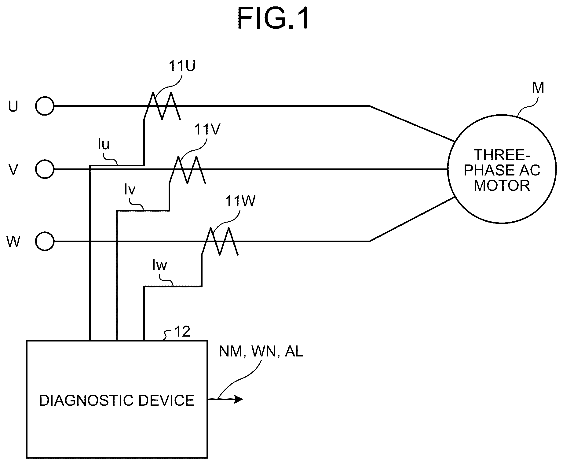
is an explanatory diagram of an insulation diagnostic device according to an embodiment.
An insulation diagnostic device 10 includes a first current transformer (CT: current transformer) 11 U that detects a U-phase current Iu that is supplied to a three-phase AC motor M, a second current transformer (CT) 11 V that detects a V-phase current Iv that is supplied to the three-phase AC motor M, a third current transformer (CT) 11 W that detects a W-phase current Iw that is supplied to the three-phase AC motor M, and a diagnostic device 12 that makes a diagnosis on the basis of the U-phase current Iu, the V-phase current Iv, and the W-phase current Iw that have been detected.
is a functional block diagram of a diagnostic device.
The diagnostic device 12 includes a phase/amplitude detection module 21 , a basic current vector calculation module 22 , a zero sequence current vector calculation module 23 , a negative sequence current vector calculation module 24 , a reference current vector storage unit 25 , a current difference vector calculation module 26 , a square sum calculation module 27 , and a determination module 28 .
In the configuration described above, the basic current vector calculation module 22 , the zero sequence current vector calculation module 23 , and the negative sequence current vector calculation module 24 function as a current vector calculation module.
The phase/amplitude detection module 21 detects a phase of the U-phase current Iu, a phase of the V-phase current Iv, a phase of the W-phase current Iw, an amplitude of the U-phase current Iu, an amplitude of the V-phase current Iv, and an amplitude of the W-phase current Iw on the basis of the U-phase current Iu, the V-phase current Iv, and the W-phase current Iw that have been detected.
In the description below, for example, in order to clearly describe that Iu is a vector, the expression “vector VIu” is used, and in order to clarify a correspondence relationship between description in sentences and description in formulae, VIu is written below an arrow for convenience sake.
The basic current vector calculation module 22 calculates a U-phase current vector VIu on the basis of the phase of the U-phase current Iu and the amplitude of the U-phase current Iu, calculates a V-phase current vector VIv on the basis of the phase of the V-phase current Iv and the amplitude of the V-phase current Iv, and calculates a W-phase current vector VIw on the basis of the phase of the W-phase current Iw and the amplitude of the W-phase current Iw.
The zero sequence current vector calculation module 23 calculates a zero sequence current vector VI 0 according to the following formula on the basis of the U-phase current vector VIu, the V-phase current vector VIv, and the W-phase current vector VIw that have been calculated.
VI 0 → = ( VIu → + VIv → + V Iw → )
The negative sequence current vector calculation module 24 calculates a negative sequence current vector VI 2 according to the following formula on the basis of the U-phase current vector VIu, the V-phase current vector VIv, and the W-phase current vector VIw that have been calculated.
VI 2 → = ( VIu → + a 2 VIv → + a VIw → )
Here, “a” is a vector operator, and is expressed as the following:
a = - 1 2 + j 3 2
The reference current vector storage unit 25 stores, as a reference zero sequence current vector VI 0 r and a reference negative sequence current vector VI 2 r , the zero sequence current vector VI 0 and the negative sequence current vector VI 2 that have been calculated in a state where a ground fault, a layer short circuit, or the like has not occurred, for example, at the time of shipping or at the time of an inspection.
In practice, the reference current vector storage unit 25 stores each of a primary reference zero sequence current vector VI 0 r _ 1 , which is a primary frequency component of the reference zero sequence current vector VI 0 r , a tertiary reference zero sequence current vector VI 0 r _ 3 , which is a tertiary frequency component of the reference zero sequence current vector VI 0 r , a quinary reference zero sequence current vector VI 0 r _ 5 , which is a quinary frequency component of the reference zero sequence current vector VI 0 r , and a septenary reference zero sequence current vector VI 0 r _ 7 , which is a septenary frequency component of the reference zero sequence current vector VI 0 r.
Moreover, the reference current vector storage unit 25 stores each of a primary reference negative sequence current vector VI 2 r _ 1 , which is a primary frequency component of the reference negative sequence current vector VI 2 r , a tertiary reference negative sequence current vector VI 2 r _ 3 , which is a tertiary frequency component of the reference negative sequence current vector VI 2 r , a quinary reference negative sequence current vector VI 2 r _ 5 , which is a quinary frequency component of the reference negative sequence current vector VI 2 r , and a septenary reference negative sequence current vector VI 2 r _ 7 , which is a septenary frequency component of the reference negative sequence current vector VI 2 r.
The current difference vector calculation module 26 calculates, as a zero sequence current difference vector DVI 0 , a difference between the zero sequence current vector VI 0 that has been calculated by the zero sequence current vector calculation module 23 and the reference zero sequence current vector VI 0 r that has been read out from the reference current vector storage unit 25 .
Furthermore, the current difference vector calculation module 26 calculates, as a negative sequence current difference vector DVI 2 , a difference between the negative sequence current vector VI 2 that has been calculated by the negative sequence current vector calculation module 24 and the reference negative sequence current vector VI 2 r that has been read out from the reference current vector storage unit 25 .
is an explanatory diagram of a primary zero sequence current vector and a primary reference zero sequence current vector.
is an explanatory diagram of calculation of a primary zero sequence current difference vector.
The current difference vector calculation module 26 calculates a primary zero sequence current difference vector DVI 0 _ 1 , by subtracting a primary zero sequence current vector VI 0 __ 1 from the primary reference zero sequence current vector VI 0 r _ 1 , as illustrated in .
Stated another way, the current difference vector calculation module 26 performs the processing described below.
DVI0_ 1 → = VI0r_ 1 → - VI0_ 1 →
is an explanatory diagram of a tertiary zero sequence current vector and a tertiary reference zero sequence current vector.
is an explanatory diagram of a quinary zero sequence current vector and a quinary reference zero sequence current vector.
is an explanatory diagram of a septenary zero sequence current vector and a septenary reference zero sequence current vector.
Similarly, the current difference vector calculation module 26 calculates the primary zero sequence current difference vector DVI 0 _ 1 , a tertiary zero sequence current difference vector DVI 0 _ 3 , a quinary zero sequence current difference vector DVI 0 _ 5 , and a septenary zero sequence current difference vector DVI 0 _ 7 , and a primary negative sequence current difference vector DVI 2 _ 1 , a tertiary negative sequence current difference vector DVI 2 _ 3 , a quinary negative sequence current difference vector DVI 2 _ 5 , and a septenary negative sequence current difference vector DVI 2 _ 7 .
The square sum calculation module 27 calculates the square sum of the primary zero sequence current difference vector DVI 0 _ 1 to the septenary zero sequence current difference vector DVI 0 _ 7 that have been calculated by the current difference vector calculation module 26 .
Similarly, the square sum calculation module 27 calculates the square sum of the primary negative sequence current difference vector DVI 2 _ 1 to the septenary negative sequence current difference vector DVI 2 _ 7 that have been calculated by the current difference vector calculation module 26 .
The determination module 28 compares the square sum SS 0 of the primary zero sequence current difference vector DVI 0 _ 1 to the septenary zero sequence current difference vector DVI 0 _ 7 and the square sum SS 2 of the primary negative sequence current difference vector DVI 2 _ 1 to the septenary negative sequence current difference vector DVI 2 _ 7 with a first threshold Vth 1 (=corresponds to a warning value) and a second threshold Vth 2 (=corresponds to a fault value) that respectively correspond to the square sums, and outputs a result of determination.
Next, an operation according to the embodiment is described.
is a flowchart of operation processing according to the embodiment.
First, the diagnostic device 12 determines whether it is a timing of detection of a fault such as a ground fault or a layer short circuit (Step S 11 ).
In the determination of Step S 11 , in a case where it has not yet been a timing of detection (Step S 11 ; No), it enters into a standby state.
In the determination of Step S 11 , in a case where it is a timing of detection (Step S 11 ; Yes), the first current transformer 11 U, the second current transformer 11 V, and the third current transformer 11 W detect the U-phase current Iu, the V-phase current Iv, and the W-phase current Iw (Step S 12 ).
Next, the diagnostic device 12 functions as the phase/amplitude detection module 21 , and detects the phase of the U-phase current Iu, the phase of the V-phase current Iv, the phase of the W-phase current Iw, the amplitude of the U-phase current Iu, the amplitude of the V-phase current Iv, and the amplitude of the W-phase current Iw on the basis of the U-phase current Iu, the V-phase current Iv, and the W-phase current Iw that have been detected (Step S 13 ).
Then, the diagnostic device 12 functions as the basic current vector calculation module 22 , calculates the U-phase current vector VIu on the basis of the phase of the U-phase current Iu and the amplitude of the U-phase current Iu, calculates the V-phase current vector VIv on the basis of the phase of the V-phase current Iv and the amplitude of the V-phase current Iv, and calculates the W-phase current vector VIw on the basis of the phase of the W-phase current Iw and the amplitude of the W-phase current Iw (Step S 14 ).
Next, the diagnostic device 12 functions as the zero sequence current vector calculation module 23 , and calculates each of the primary zero sequence current vector VI 0 __ 1 , which is a primary frequency component of the zero sequence current vector VI 0 , a tertiary zero sequence current vector VI 0 _ 3 , which is a tertiary frequency component of the zero sequence current vector VI 0 , a quinary zero sequence current vector VI 0 _ 5 , which is a quinary frequency component of the zero sequence current vector VI 0 , and a septenary zero sequence current vector VI 0 _ 7 , which is a septenary frequency component of the zero sequence current vector VI 0 (Step S 15 ).
Then, the diagnostic device 12 functions as the negative sequence current vector calculation module 24 , and calculates the negative sequence current vector VI 2 according to the following formula on the basis of the U-phase current vector VIu, the V-phase current vector VIv, and the W-phase current vector VIw that have been calculated (Step S 16 ).
VI 2 → = ( VIu → + a 2 VIv → + a VIw → )
Here, “a” is a vector operator, and is expressed as the following:
a = - 1 2 + j 3 2
More specifically, the diagnostic device 12 serves as the negative sequence current vector calculation module 24 , and calculates each of a primary negative sequence current vector VI 2 _ 1 , which is a primary frequency component of the negative sequence current vector VI 2 , a tertiary negative sequence current vector VI 2 _ 3 , which is a tertiary frequency component of the negative sequence current vector VI 2 , a quinary negative sequence current vector VI 2 _ 5 , which is a quinary frequency component of the negative sequence current vector VI 2 , and a septenary negative sequence current vector VI 2 _ 7 , which is a septenary frequency component of the negative sequence current vector VI 2 .
Next, the diagnostic device 12 reads out the reference zero sequence current vector VI 0 r and the reference negative sequence current vector VI 2 r that are stored in the reference current vector storage unit 25 (Step S 17 ).
As a result of this, the diagnostic device 12 functions as the current difference vector calculation module 26 , calculates, as the zero sequence current difference vector DVI 0 , a difference between the zero sequence current vector VI 0 that has been calculated by the zero sequence current vector calculation module 23 and the reference zero sequence current vector VI 0 r that has been read out from the reference current vector storage unit 25 , and calculates, as the negative sequence current difference vector DVI 2 , a difference between the negative sequence current vector VI 2 that has been calculated by the negative sequence current vector calculation module 24 and the reference negative sequence current vector VI 2 r that has been read out from the reference current vector storage unit 25 (Step S 18 ).
More specifically, the diagnostic device 12 serves as the current difference vector calculation module 26 , and calculates, as the primary zero sequence current difference vector DVI 0 _ 1 , a difference between the primary zero sequence current vector VI 0 _ 1 that is the primary frequency component of the zero sequence current vector VI 0 that has been calculated by the zero sequence current vector calculation module 23 , and the primary reference zero sequence current vector VI 0 r _ 1 that is the primary frequency component of the reference zero sequence current vector VI 0 r that has been read out from the reference current vector storage unit 25 .
Similarly, the diagnostic device 12 serves as the current difference vector calculation module 26 , and calculates, as the tertiary zero sequence current difference vector DVI 0 _ 3 , a difference between the tertiary zero sequence current vector VI 0 _ 3 that is the tertiary frequency component of the zero sequence current vector VI 0 that has been calculated by the zero sequence current vector calculation module 23 , and the tertiary reference zero sequence current vector VI 0 r _ 3 that is the tertiary frequency component of the reference zero sequence current vector VI 0 r that has been read out from the reference current vector storage unit 25 .
Furthermore, the diagnostic device 12 serves as the current difference vector calculation module 26 , and calculates, as the quinary zero sequence current difference vector DVI 0 _ 5 , a difference between the quinary zero sequence current vector VI 0 _ 5 that is the quinary frequency component of the zero sequence current vector VI 0 that has been calculated by the zero sequence current vector calculation module 23 , and the quinary reference zero sequence current vector VI 0 r _ 5 that is the quinary frequency component of the reference zero sequence current vector VI 0 r that has been read out from the reference current vector storage unit 25 .
Similarly, the diagnostic device 12 serves as the current difference vector calculation module 26 , and calculates, as the septenary zero sequence current difference vector DVI 0 _ 7 , a difference between the septenary zero sequence current vector VI 0 _ 7 that is the septenary frequency component of the zero sequence current vector VI 0 that has been calculated by the zero sequence current vector calculation module 23 , and the septenary reference zero sequence current vector VI 0 r _ 7 that is the septenary frequency component of the reference zero sequence current vector VI 0 r that has been read out from the reference current vector storage unit 25 .
Furthermore, the diagnostic device 12 serves as the current difference vector calculation module 26 to handle a negative sequence current vector, and calculates, as the primary negative sequence current difference vector DVI 2 _ 1 , a difference between the primary negative sequence current vector VI 2 _ 1 that is the primary frequency component of the negative sequence current vector VI 2 that has been calculated by the negative sequence current vector calculation module 24 , and the primary reference negative sequence current vector VI 2 r _ 1 that is the primary frequency component of the reference negative sequence current vector VI 2 r that has been read out from the reference current vector storage unit 25 .
Similarly, the diagnostic device 12 serves as the current difference vector calculation module 26 , and calculates, as the tertiary negative sequence current difference vector DVI 2 _ 3 , a difference between the tertiary negative sequence current vector VI 2 _ 3 that is the tertiary frequency component of the negative sequence current vector VI 2 that has been calculated by the negative sequence current vector calculation module 24 , and the tertiary reference negative sequence current vector VI 2 r _ 3 that is the tertiary frequency component of the reference negative sequence current vector VI 2 r that has been read out from the reference current vector storage unit 25 .
Furthermore, the diagnostic device 12 serves as the current difference vector calculation module 26 , and calculates, as the quinary negative sequence current difference vector DVI 2 _ 5 , a difference between the quinary negative sequence current vector VI 2 _ 5 that is the quinary frequency component of the negative sequence current vector VI 2 that has been calculated by the negative sequence current vector calculation module 24 , and the quinary reference negative sequence current vector VI 2 r _ 5 that is the quinary frequency component of the reference negative sequence current vector VI 2 r that has been read out from the reference current vector storage unit 25 .
Furthermore, the diagnostic device 12 serves as the current difference vector calculation module 26 , and calculates, as the septenary negative sequence current difference vector DVI 2 _ 7 , a difference between the septenary negative sequence current vector VI 2 _ 7 that is the septenary frequency component of the negative sequence current vector VI 2 that has been calculated by the negative sequence current vector calculation module 24 , and the septenary reference negative sequence current vector VI 2 r _ 7 that is the septenary frequency component of the reference negative sequence current vector VI 2 r that has been read out from the reference current vector storage unit 25 .
As a result of these, the diagnostic device 12 functions as the square sum calculation module 27 , calculates the square sum of the primary zero sequence current difference vector DVI 0 _ 1 to the septenary zero sequence current difference vector DVI 0 _ 7 that have been calculated by the current difference vector calculation module 26 , outputs the square sum to the determination module 28 , and calculates the square sum of the primary negative sequence current difference vector DVI 2 _ 1 to the septenary negative sequence current difference vector DVI 2 _ 7 that have been calculated by the current difference vector calculation module 26 (Step S 19 ).
As a result of this, the diagnostic device 12 , functions as the determination module 28 , compares the square sum SS 0 of the primary zero sequence current difference vector DVI 0 _ 1 to the septenary zero sequence current difference vector DVI 0 _ 7 and the square sum SS 2 of the primary negative sequence current difference vector DVI 2 _ 1 to the septenary negative sequence current difference vector DVI 2 _ 7 with the first threshold Vth 1 (=corresponds to the warning value) and the second threshold Vth 2 (=corresponds to the fault value) that respectively correspond to the square sums, and outputs, as a result of determination, a normal signal NM, a warning signal WN, or a fault signal AL (Step S 20 ).
Here, the square sum SS 0 and the square sum SS 2 are expressed according to the formulae described below.
SS 0 = √ ( [ DV10_ 1 ] 2 + [ DV10_ 3 ] 2 + [ DV10_ 5 ] 2 + [ DV10_ 7 ] 2 ) SS 2 = √ ( [ DV12_ 1 ] 2 + [ DV12_ 3 ] 2 + [ DV12_ 5 ] 2 + [ DV12_ 7 ] 2 )
is an explanatory diagram of examples of the square sum, the first threshold, and the second threshold.
illustrates a change with time in the square sum SS (the square sum SS 0 or the square sum SS 2 ) at a predetermined detection timing (in the case of the example of , time t 1 to time t 7 ).
As illustrated in , from time t 1 to time t 3 , the square sum SS hardly changes, and is less than the first threshold Vth 1 , and therefore the determination module 28 outputs the normal signal NM that corresponds to a result indicating normality.
Then, at time t 4 and time t 5 , the square sum SS has increased in comparison with the cases of time t 1 to time t 3 , but is still less than the first threshold Vth 1 , and therefore the determination module 28 outputs the normal signal NM that corresponds to a result indicating normality.
In contrast to these, at time t 6 , the square sum SS has increased, exceeds the first threshold Vth 1 , and is less than the second threshold Vth 2 , and therefore the determination module 28 determines that it is in a state where there is a high probability of the ground fault or the layer short circuit, and outputs the warning signal WN.
Moreover, at time t 7 , the square sum SS has further increased, and exceeds the second threshold Vth 2 , and therefore the determination module 28 determines that it is in a fault state where the ground fault or the layer short circuit has occurred, and outputs the fault signal AL.
As described above, according to the present embodiment, the primary reference zero sequence current vector VI 0 r _ 1 to the septenary reference zero sequence current vector VI 0 r _ 7 and the primary reference negative sequence current vector VI 2 r _ 1 to the septenary reference negative sequence current vector VI 2 r _ 7 , which are values in an initial state (a normal state) of the primary zero sequence current vector VI 0 __ 1 to the septenary zero sequence current vector VI 0 _ 7 that are primary to septenary components of the zero sequence current vector VI 0 , and the primary negative sequence current vector VI 2 _ 1 to the septenary negative sequence current vector VI 2 _ 7 that are primary to septenary components of the negative sequence current vector VI 2 , are grasped.
Then, the primary zero sequence current difference vector DVI 0 _ 1 to the septenary zero sequence current difference vector DVI 0 _ 7 and the primary negative sequence current difference vector DVI 2 _ 1 to the septenary negative sequence current difference vector DVI 2 _ 7 are calculated on the basis of the primary zero sequence current vector VI 0 _ 1 to the septenary zero sequence current vector VI 0 _ 7 and the primary negative sequence current vector VI 2 _ 1 to the septenary negative sequence current vector VI 2 _ 7 that have been detected in an operation state of the three-phase AC motor M.
Moreover, a deterioration sign state in which there is a high probability that the ground fault, the layer short circuit, or the like will occur is detected in real time on the basis of the primary zero sequence current difference vector DVI 0 _ 1 to the septenary zero sequence current difference vector DVI 0 _ 7 and the primary negative sequence current difference vector DVI 2 _ 1 to the septenary negative sequence current difference vector DVI 2 _ 7 that have been calculated, or a fault state of the ground fault, the layer short circuit, or the like can be detected in real time.
The embodiment of the present invention that has been described above is not restrictive of the scope of the invention, and is merely an example included in the scope of the invention. An embodiment of the present invention may be embodied by making changes, omissions, and additions of, for example, at least some of the specific purposes, structures, shapes, workings, and effects to the embodiment described above without departing from the gist of the invention.
For example, in the description above, with respect to the zero sequence current vector and the negative sequence current vector, the zero sequence current difference vector and the negative sequence current difference vector have been respectively obtained. However, a configuration in which an insulation diagnosis is made by using either the zero sequence current difference vector or the negative sequence current difference vector can also be employed.
Furthermore, in the description above, processing has been performed on current vectors of a primary frequency and a tertiary frequency, a quinary frequency, and a septenary frequency that serve as higher-order frequencies. However, processing may be performed on current vectors of the primary frequency and at least one higher-order frequency.
EXPLANATIONS OF LETTERS OR NUMERALS
•
• 10 INSULATION DIAGNOSTIC DEVICE, 11 U FIRST CURRENT TRANSFORMER, 11 V SECOND CURRENT TRANSFORMER, 12 DIAGNOSTIC DEVICE, 21 PHASE/AMPLITUDE DETECTION MODULE, 22 CURRENT VECTOR CALCULATION MODULE, 23 ZERO SEQUENCE CURRENT VECTOR CALCULATION MODULE, 24 NEGATIVE SEQUENCE CURRENT VECTOR CALCULATION MODULE, 25 REFERENCE CURRENT VECTOR STORAGE UNIT, 26 CURRENT DIFFERENCE VECTOR CALCULATION MODULE, 27 SQUARE SUM CALCULATION MODULE, 28 DETERMINATION MODULE, AL FAULT SIGNAL, DVI 0 _ 1 to DVI 0 _ 7 PRIMARY ZERO SEQUENCE CURRENT DIFFERENCE VECTOR TO SEPTENARY ZERO SEQUENCE CURRENT DIFFERENCE VECTOR, DVI 2 _ 1 to DVI 2 _ 7 PRIMARY NEGATIVE SEQUENCE CURRENT DIFFERENCE VECTOR TO SEPTENARY NEGATIVE SEQUENCE CURRENT DIFFERENCE VECTOR, Iu U-PHASE CURRENT, Iv V-PHASE CURRENT, IW W-PHASE CURRENT, M THREE-PHASE AC MOTOR, NM NORMAL SIGNAL, SS, SS 0 , SS 2 SQUARE SUM, VIu U-PHASE CURRENT VECTOR, Viv V-PHASE CURRENT VECTOR, VIw W-PHASE CURRENT VECTOR, VI 0 ZERO SEQUENCE CURRENT VECTOR, VI 0 _ 1 to VI 0 _ 7 PRIMARY ZERO SEQUENCE CURRENT VECTOR TO SEPTENARY ZERO SEQUENCE CURRENT VECTOR, VI 0 r REFERENCE ZERO SEQUENCE CURRENT VECTOR, VI 0 r _ 1 to VI 0 r _ 7 PRIMARY REFERENCE ZERO SEQUENCE CURRENT VECTOR TO SEPTENARY REFERENCE ZERO SEQUENCE CURRENT VECTOR, VI 2 NEGATIVE SEQUENCE CURRENT VECTOR, VI 2 _ 1 to VI 2 _ 7 PRIMARY NEGATIVE SEQUENCE CURRENT VECTOR TO SEPTENARY NEGATIVE SEQUENCE CURRENT VECTOR, VI 2 r REFERENCE NEGATIVE SEQUENCE CURRENT VECTOR, VI 2 r _ 1 to VI 2 r _ 7 PRIMARY REFERENCE NEGATIVE SEQUENCE CURRENT VECTOR TO SEPTENARY REFERENCE NEGATIVE SEQUENCE CURRENT VECTOR, Vth 1 FIRST THRESHOLD, Vth 2 SECOND THRESHOLD, WN WARNING SIGNAL
Figures (7)
Citations
This patent cites (5)
- US11899045
- US2017/0373630
- US2024/0125840
- US2025/0244376
- US2017-015444