Abstract
A gas sensor element ( 10 ) which includes an element body portion ( 100 ); a pump cell ( 110 ) which is configured to adjust a concentration of oxygen in a gas to be measured which is introduced into the element body portion ( 100 ); a detection chamber ( 160 ) which is formed inside the element body portion ( 100 ) and into which the gas to be measured in which the concentration of oxygen has been adjusted is introduced; and a layer-shaped cathode electrode ( 133 ) which is housed in the detection chamber ( 160 ) and configured to decompose NO. A relationship between a volume V 1 of the detection chamber ( 160 ) and a volume V 2 of the cathode electrode ( 133 ) in the gas sensor element ( 10 ) satisfies either one of conditions (A) and (B) as defined herein.
Claims (4)
1 . A gas sensor element comprising: an element body portion which includes a plurality of laminated ceramic sheets; a pump cell which is configured to adjust a concentration of oxygen in a gas to be measured which is introduced into the element body portion; a detection chamber which is formed inside the element body portion and into which the gas to be measured in which the concentration of oxygen has been adjusted is introduced; and a layer-shaped cathode electrode which is housed in the detection chamber and configured to decompose NO, wherein a relationship between a volume V 1 of the detection chamber and a volume V 2 of the cathode electrode satisfies either a condition (A) or a condition (B) described below, Condition (A): the volume V 1 is not less than 0.047 mm 3 and not greater than 0.057 mm 3 and the volume V 2 is not less than 0.031 mm 3 and not greater than 0.047 mm 3 , and Condition (B): the volume V 1 is not less than 0.057 mm 3 and not greater than 0.117 mm 3 and the volume V 2 is not less than 0.047 mm 3 and not greater than 0.059 mm 3 .
Show 3 dependent claims
2 . The gas sensor element as claimed in claim 1 , wherein the detection chamber penetrates at least one ceramic sheet among the plurality of ceramic sheets, in a thickness direction, and in a region where the detection chamber penetrates the at least one ceramic sheet, a cross-sectional area of the detection chamber in a plane direction of the at least one ceramic sheet is not less than 0.05 mm 2 and not greater than 0.35 mm 2 .
3 . The gas sensor element as claimed in claim 1 , further comprising: a solid electrolyte layer which forms a part of the element body portion and has a front surface on which the cathode electrode is formed; and an anode electrode which is disposed on the front surface of the solid electrolyte layer and configured to receive oxygen ions that are generated at the cathode electrode in accordance with decomposition of NO and move in the solid electrolyte layer.
4 . A gas sensor comprising the gas sensor element as claimed in claim 1 .
Full Description
Show full text →
BACKGROUND OF THE INVENTION
1. Field of the Invention
The present disclosure relates to a gas sensor element and a gas sensor.
2. Description of the Related Art
A gas sensor that detects the concentration of NO x contained in exhaust gas of an internal combustion engine is known. Such a type of gas sensor utilizes the oxygen ion conductivity of zirconia (ZrO 2 ) heated to high temperatures, and in an equilibrium reaction of NO with N 2 and O 2 . Further, while the decomposition of NO is accelerated by removing oxygen (O 2 ), oxygen generated by the decomposition is measured, whereby an NO x concentration is obtained.
As such a gas sensor, for example, a gas sensor that includes a gas sensor element including a first pump cell, a detection cell, a second pump cell, a first measurement chamber, a second measurement chamber, etc., is known (see, for example, Patent Document 1).
The first pump cell performs pumping-out and pumping-in (so called “pumping”) of oxygen in exhaust gas between the first measurement chamber and the outside, and adjusts the concentration of oxygen in the exhaust gas. The concentration of oxygen in the first measurement chamber is controlled to a low level by the action of the first pump cell. The detection cell measures the concentration of oxygen in the exhaust gas on which pumping-out and pumping-in of oxygen has been performed by the first pump cell, and acts to apply a current (first pump current) to the first pump cell such that an output voltage (electromotive force) corresponding to the concentration of oxygen is constant.
The exhaust gas in the first measurement chamber in which the concentration of oxygen is controlled as described above is introduced into the second measurement chamber through a predetermined path in the gas sensor element. The second pump cell detects an NO x concentration from the exhaust gas introduced into the second measurement chamber. The second pump cell includes a pair of electrodes, and one electrode (cathode electrode, Ip2− electrode) of these electrodes is housed in the second measurement chamber. NO in the exhaust gas introduced into the second measurement chamber is decomposed into N 2 and O 2 at the electrode in the second measurement chamber. A second pump current for pumping out the oxygen generated by the decomposition to the other electrode (anode electrode) flows through the second pump cell. The second pump current is proportional to the NO concentration, so that the concentration of NO x (NO) in the exhaust gas is obtained by measuring the second pump current.
•
• [Patent Document 1] Japanese Patent Application Laid-Open (kokai) No. 2017-207466
3. Problems to be Solved by the Disclosure
In a conventional gas sensor, improved responsiveness to NO is required by shortening the rise time of the output waveform of the second pump current described above.
SUMMARY OF THE DISCLOSURE
It is therefore an object of the present disclosure to provide a gas sensor element and a gas sensor having excellent NO responsiveness.
The means for solving the above problems are as follows.
<1> A gas sensor element including: an element body portion which includes a plurality of laminated ceramic sheets; a pump cell which is configured to adjust a concentration of oxygen in a gas to be measured which is introduced into the element body portion; a detection chamber which is formed inside the element body portion and into which the gas to be measured in which the concentration of oxygen has been adjusted is introduced; and a layer-shaped cathode electrode which is housed in the detection chamber and configured to decompose NO, wherein a relationship between a volume V 1 of the detection chamber and a volume V 2 of the cathode electrode satisfies either one of a condition (A) and a condition (B) described below,
•
• Condition (A): the volume V 1 is not less than 0.047 mm 3 and not greater than 0.065 mm 3 and the volume V 2 is not less than 0.030 mm 3 and not greater than 0.059 mm 3 , and • Condition (B): the volume V 1 is not less than 0.047 mm 3 and not greater than 0.125 mm 3 and the volume V 2 is not less than 0.044 mm 3 and not greater than 0.059 mm 3 .
<2> The gas sensor element according to the above <1>, wherein the detection chamber penetrates at least one ceramic sheet among the plurality of ceramic sheets, in a thickness direction, and in a region where the detection chamber penetrates the ceramic sheet, a cross-sectional area of the detection chamber in a plane direction of the ceramic sheet is not less than 0.05 mm 2 and not greater than 0.35 mm 2 .
<3> The gas sensor element according to the above <1> or <2>, further including: a solid electrolyte layer which forms a part of the element body portion and has a front surface on which the cathode electrode is formed; and an anode electrode which is disposed on the front surface of the solid electrolyte layer and configured to receive oxygen ions that are generated at the cathode electrode in accordance with decomposition of NO and move in the solid electrolyte layer.
<4> A gas sensor including the gas sensor element according to any one of the above <1> to <3>.
Effects of the Disclosure
According to the present disclosure, it is possible to provide a gas sensor element and a gas sensor having excellent NO responsiveness.
BRIEF DESCRIPTION OF THE DRAWINGS
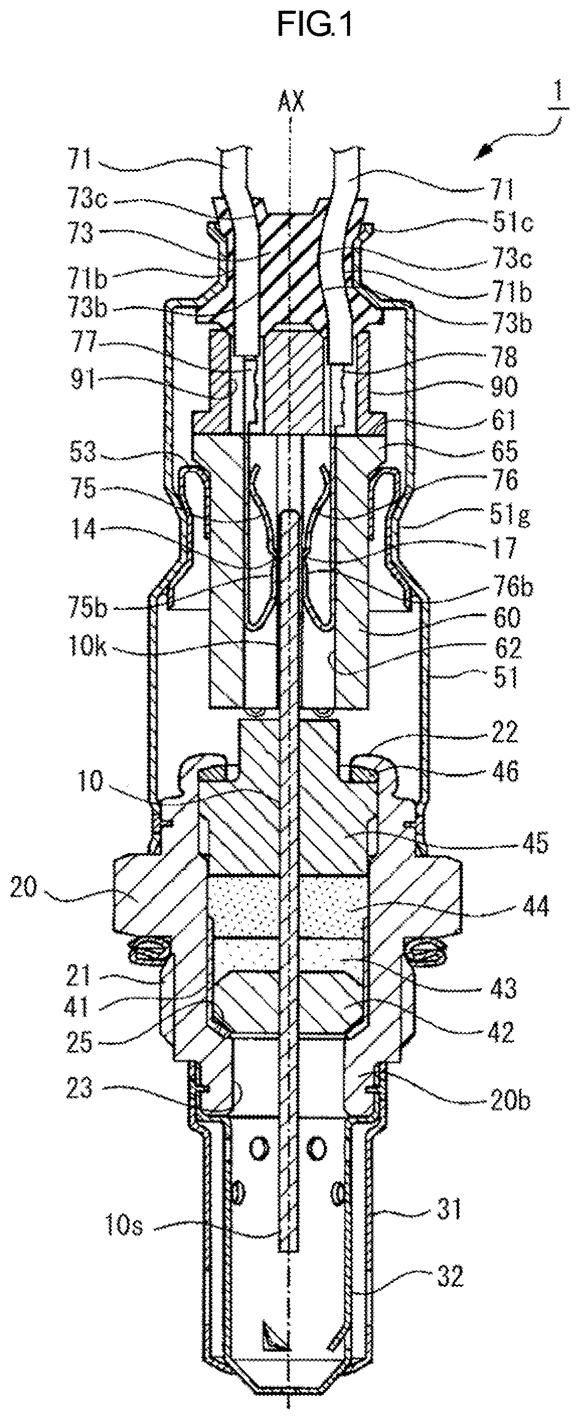
is a longitudinal cross-sectional view of a gas sensor according to Embodiment 1.
is perspective view of a gas sensor element according to Embodiment 1.
is a cross-sectional view taken along a line A-A in .
is an exploded perspective view of the gas sensor element.
is an enlarged cross-sectional view of the gas sensor element around a second measurement chamber.
is a graph showing the output waveform of a second pump current flowing through an Ip2 cell of the gas sensor element.
is a diagram showing the test results of the responsiveness of gas sensors in coordinates.
DESCRIPTION OF REFERENCE NUMERALS
Reference numerals used to identify various features in the drawings include the following.
•
• 1 : gas sensor • 10 : gas sensor element • 100 : element body portion • 110 : IP1 cell (pump cell) • 111 s , 121 s , 131 s : insulating layer (ceramic sheet) • 130 : Ip2 cell • 132 : Ip2+ electrode (anode electrode) • 133 : Ip2− electrode (cathode electrode) • 160 : second measurement chamber (detection chamber) • 161 : introduction chamber • 162 : housing chamber • V 1 : volume of detection chamber • V 2 : volume of cathode electrode
DETAILED DESCRIPTION OF THE PREFERRED EMBODIMENTS
The present disclosure is described in detail below with reference to the drawings. However, the present disclosure should not be construed as being limited thereto.
Embodiment 1
Hereinafter, Embodiment 1 of the present disclosure will be described with reference to to . is a longitudinal cross-sectional view of a gas sensor (NO x sensor) 1 according to Embodiment 1, is a perspective view of a gas sensor element 10 according to Embodiment 1, is a cross-sectional view taken along a line A-A in , and is an exploded perspective view of the gas sensor element 10 .
shows an axial line AX of the gas sensor 1 as a straight line (alternate long and short dashed line) along the up-down direction. In the present specification, a direction along the axial line AX direction of the gas sensor 1 is also referred to as a “longitudinal direction”, and a direction perpendicularly intersecting the axial line AX is also referred to as a “width direction”. In addition, in the present specification, the lower side of the gas sensor 1 shown in is referred to as a “front end side”, and the side opposite thereto (upper side in ) is referred to as a “rear end side”. Moreover, for the convenience of description, the upper side in to is referred to as a “front side (front surface side)” of the gas sensor element 10 , and the lower side in to is referred to as a “rear side (rear surface side)” of the gas sensor element 10 .
The gas sensor 1 includes the gas sensor element 10 capable of detecting the concentration of NO x in exhaust gas which is a gas to be measured. The gas sensor 1 is an NO x sensor that is mounted and used on an exhaust pipe (not shown) of an internal combustion engine, and includes a tubular metal shell 20 having a threaded portion 21 adapted for fixing the gas sensor to the exhaust pipe and is formed at a predetermined position on the outer surface thereof. The gas sensor element 10 has an elongated plate shape extending along the axial line AX direction, as a whole, and such a gas sensor element 10 is held inside the metal shell 20 .
The gas sensor 1 includes: a tubular holding member 60 having an insertion hole 62 into which a rear end portion 10 k of the gas sensor element 10 is inserted; and six terminal members held inside the holding member 60 . In , for the convenience of description, only two terminal members 75 and 76 of the six terminal members are shown.
In the rear end portion 10 k of the gas sensor element 10 , as shown in , a total of six electrode terminal portions 13 to 18 are formed so as to have a rectangular shape in a plan view. In , only the electrode terminal portions 14 and 17 are shown. The aforementioned terminal members are brought into elastic contact with and electrically connected to these electrode terminal portions 13 to 18 , respectively. For example, an element contact portion 75 b of the terminal member 75 is brought into elastic contact with and electrically connected to the electrode terminal portion 14 , and an element contact portion 76 b of the terminal member 76 is brought into elastic contact with and electrically connected to the electrode terminal portion 17 .
Moreover, different lead wires 71 are electrically connected to the six terminal members (terminal members 75 , 76 , etc.), respectively. For example, as shown in , a core wire of a lead wire 71 is crimped and held by a lead wire holding portion 77 of the terminal member 75 . In addition, a core wire of another lead wire 71 is crimped and held by a lead wire holding portion 78 of the terminal member 76 .
As shown in , in one main surface 10 a (on the front side) out of two main surfaces 10 a and 10 b of the rear end portion 10 k of the gas sensor element 10 , an opening-like atmospheric introduction port 10 h is provided at a location on the front end side with respect to the electrode terminal portions 13 to 15 and on the rear end side with respect to a ceramic sleeve 45 (see ) described below. The atmospheric introduction port 10 h is located in the insertion hole 62 of the holding member 60 .
The metal shell 20 is a tubular member having a through hole 23 which penetrates the metal shell 20 in the axial line AX direction. The metal shell 20 includes a shelf portion 25 which projects radially inward and forms a part of the through hole 23 . The metal shell 20 holds the gas sensor element 10 inside the through hole 23 in a state where a front end portion 10 s of the gas sensor element 10 projects out of the front end side of the metal shell 20 (downward in ) and the rear end portion 10 k of the gas sensor element 10 projects out of the rear end side of the metal shell 20 (upward in ).
Moreover, inside the through hole 23 of the metal shell 20 , an annular ceramic holder 42 , two talc rings 43 and 44 formed by annularly filling with talc powder, and the ceramic sleeve 45 are disposed. More specifically, the ceramic holder 42 , the talc rings 43 and 44 , and the ceramic sleeve 45 are laminated in this order from the front end side to the rear end side of the metal shell 20 so as to surround the gas sensor element 10 which extends in the axial line AX.
A metal cup 41 is disposed between the ceramic holder 42 and the shelf portion 25 of the metal shell 20 . In addition, a crimp ring 46 is disposed between the ceramic sleeve 45 and a crimp portion 22 of the metal shell 20 . The crimp portion 22 of the metal shell 20 is crimped such that the ceramic sleeve 45 is pressed on the front end side via the crimp ring 46 .
An outer protector 31 and an inner protector 32 each made of metal (for example, stainless steel) and having a plurality of holes are attached to a front end portion 20 b of the metal shell 20 by welding so as to cover the front end portion 10 s of the gas sensor element 10 . In addition, an outer casing 51 is attached to a rear end portion of the metal shell 20 by welding. The outer casing 51 has a tubular shape extending in the axial line AX direction, as a whole, and surrounds the gas sensor element 10 .
The holding member 60 is a tubular member made of an insulating material (for example, alumina) and having the insertion hole 62 which penetrates the member in the axial line AX direction. The above-described six terminal members (terminal members 75 and 76 , etc.) are disposed inside the insertion hole 62 (see ). A flange portion 65 is formed at a rear end portion of the holding member 60 so as to project radially outward. The holding member 60 is held by an inner support member 53 such that the flange portion 65 is in contact with the inner support member 53 . The inner support member 53 is held by a crimp portion 51 g , of the outer casing 51 , which is crimped toward the radially inner side.
An insulating member 90 is disposed on a rear end surface 61 of the holding member 60 . The insulating member 90 is made of an insulating material (for example, alumina), and has a tubular shape as a whole. In the insulating member 90 , a total of six through holes 91 are formed so as to penetrate the insulating member 90 in the axial line AX direction. The lead wire holding portions 77 , 78 , etc., of the above-described terminal members are disposed in the through holes 91 .
Moreover, in the outer casing 51 , an elastic seal member 73 made of a fluororubber is disposed on the radially inner side of a rear end opening 51 c located on the rear end side. In the elastic seal member 73 , a total of six cylindrical insertion holes 73 c are formed so as to extend in the axial line AX direction. Each insertion hole 73 c is formed by an insertion hole surface 73 b (cylindrical inner wall surface) of the elastic seal member 73 . One lead wire 71 is inserted into each insertion hole 73 c . Each lead wire 71 extends outside the gas sensor 1 through the insertion hole 73 c of the elastic seal member 73 . The elastic seal member 73 is elastically compressed and deformed in the radial direction by radially inwardly crimping the rear end opening 51 c of the outer casing 51 , whereby the insertion hole surface 73 b and an outer circumferential surface 71 b of the lead wire 71 are brought into close contact with each other to be sealed in a watertight manner.
As shown in , the gas sensor element 10 includes an element body portion 100 which has a plurality of plate-shaped insulating layers (ceramic sheets) 111 s , 121 s , and 131 s , solid electrolyte bodies 111 e , 121 e , and 131 e formed in the plate-shaped insulating layers 111 s , 121 s , and 131 s , and insulators 140 and 145 disposed between the plate-shaped insulating layers 111 s , 121 s , and 131 s . Each of the insulators 140 and 145 is made of a dense ceramic (for example, alumina). The gas sensor element 10 further includes a heater 261 disposed on the rear surface side of the solid electrolyte body 131 e . The heater 261 includes two plate-shaped insulators 262 and 263 mainly made of alumina, and a heater pattern 264 embedded between the insulators 262 and 263 . The heater pattern 264 is composed of a film-shaped pattern mainly made of platinum (Pt).
Each of the solid electrolyte bodies 111 e , 121 e , and 131 e has a substantially rectangular shape in a plan view. The solid electrolyte body 111 e is formed so as to overlap an opening 111 a provided on the front end side (left side in ) in the plate-shaped insulating layer 111 s which extends in the axial line AX direction. The solid electrolyte body 121 e is formed so as to overlap an opening 121 a provided on the front end side (left side in ) in the plate-shaped insulating layer 121 s which extends in the axial line AX direction. The solid electrolyte body 131 e is formed so as to overlap an opening 131 a provided on the front end side (left side in ) in the plate-shaped insulating layer 131 s which extends in the axial line AX direction. The solid electrolyte bodies 111 e , 121 e , and 131 e may be formed so as to be embedded in the corresponding openings 111 a , 121 a , and 131 a , respectively, or may be formed by transferring separately prepared sheet-shaped members to predetermined locations.
The insulators 140 and 145 are each composed of a fired printed layer having a smaller thickness than the insulating layer (ceramic sheet) 121 s , etc.
The solid electrolyte bodies (solid electrolyte layers) 111 e , 121 e , and 131 e are made of zirconia which is a solid electrolyte, and have oxygen ion conductivity. A porous Ip1+ electrode 112 is provided on the front surface side of the solid electrolyte body 111 e . In addition, a porous Ip1− electrode 113 is provided on the rear surface side of the solid electrolyte body 111 e . Furthermore, the front surface of the Ip1+ electrode 112 is covered with a porous layer 114 . An Ip1+ lead 116 is connected to the Ip1+ electrode 112 (see and ). In addition, an Ip1− lead 117 (see ) is connected to the Ip1− electrode 113 .
As shown in , a plate-shaped dense layer 118 B extending in the axial line AX direction is laminated on the respective front surfaces of the Ip1+ electrode 112 and the Ip1+ lead 116 . The dense layer 118 B is made of a gas-impermeable material such as alumina. An opening 118 Ba having a rectangular shape in a plan view is provided on the front end side of the dense layer 118 B. The above-described porous layer 114 is formed so as to fill the opening 118 Ba.
As shown in , a gas-impermeable dense layer 118 including a void 10 G and made of alumina or the like is disposed on the front surface side of the dense layer 118 B. A part of the porous layer 114 is exposed from the void 10 G. In the plate-shaped dense layer 118 which extends in the axial line AX direction, the void 10 G extends straight from a portion near the porous layer 114 to a portion connected to the atmospheric introduction port 10 h . In the plate-shaped dense layer 118 which extends in the axial line AX direction, through holes for electrical conduction with the electrode terminal portions 13 , 14 , and 15 are provided on the rear end side.
A gas-impermeable dense layer 115 made of alumina or the like is laminated on the front surface of the dense layer 118 . When the dense layer 115 is laminated as described above, the void 10 G is closed by the dense layer 115 .
In the dense layer 115 , the atmospheric introduction port 10 h is formed at a position overlapping the rear end of the void 10 G which extends in the longitudinal direction (axial line AX direction). The atmospheric introduction port 10 h is composed of an opening penetrating the dense layer 115 in the thickness direction. Such an atmospheric introduction port 10 h is connected to the void 10 G. The atmospheric introduction port 10 h is open on the rear end side with respect to first porous bodies 151 described below, and, rather than exhaust gas, atmospheric air can be introduced therethrough. Accordingly, the Ip1+ electrode 112 is exposed to the atmospheric air introduced from the atmospheric introduction port 10 h via the porous layer 114 .
The solid electrolyte body 111 e , the Ip1+ electrode 112 , and the Ip1− electrode 113 form an Ip1 cell (first pump cell; an example of the pump cell of the present disclosure) 110 . According to a pump current Ip1 (first pump current) applied between the Ip1+ electrode 112 and the Ip1− electrode 113 , the Ip1 cell 110 performs pumping-out and pumping-in of oxygen (so called “oxygen pumping”) between the atmosphere (atmospheric air in the void 10 G) with which the Ip1+ electrode 112 contacts and the atmosphere (atmosphere in a first measurement chamber 150 described below, that is, a gas to be measured which is outside the gas sensor element 10 ) with which the Ip1− electrode 113 contacts. As described above, the Ip1 cell 110 adjusts the concentration of oxygen in the gas to be measured (exhaust gas) introduced into the element body portion 100 .
A porous Vs− electrode 122 is provided on the front surface side of the solid electrolyte body 121 e . In addition, a porous Vs+ electrode 123 is provided on the rear surface side of the solid electrolyte body 121 e.
The first measurement chamber 150 is formed between the solid electrolyte body 111 e and the solid electrolyte body 121 e in the lamination direction. The first measurement chamber 150 is composed of an inner space S 1 , in the gas sensor element 10 , into which a gas to be measured (exhaust gas) flowing in an exhaust passage in the exhaust pipe is first introduced, and communicates with the outside of the gas sensor element 10 through gas-permeable and water-permeable first porous bodies (diffusion resistance portions) 151 (see and ). Each first porous body 151 is provided on the lateral side of the first measurement chamber 150 as a partition to the outside of the gas sensor element 10 . Such first porous bodies 151 limit the flowing amount per unit time (diffusion rate) of the exhaust gas into the first measurement chamber 150 . The first porous bodies 151 are made of a porous ceramic.
A second porous body 152 which limits the flowing amount per unit time of the exhaust gas is provided on the rear end side of the first measurement chamber 150 (right side in ) as a partition between the first measurement chamber 150 and a second measurement chamber 160 described below.
The solid electrolyte body 121 e , the Vs− electrode 122 , and the Vs+ electrode 123 form a Vs cell (detection cell) 120 . The Vs cell 120 generates an electromotive force mainly according to the difference in oxygen partial pressure between the atmospheres separated by the solid electrolyte body 121 e (the atmosphere in the first measurement chamber 150 with which the Vs− electrode 122 contacts and the atmosphere in a reference oxygen chamber 170 with which the Vs+ electrode 123 contacts).
A porous Ip2+ electrode (anode electrode) 132 and a porous Ip2− electrode (cathode electrode) 133 are provided on the front surface side of the solid electrolyte body 131 e.
The reference oxygen chamber 170 is formed as an isolated small space between the Ip2+ electrode 132 and the Vs+ electrode 123 . The reference oxygen chamber 170 is formed by an opening 145 b formed in the insulator 145 . In the reference oxygen chamber 170 , a porous body 171 made of ceramic is disposed on the Ip2+ electrode 132 side (see ).
Moreover, the second measurement chamber 160 composed of an inner space S 2 is formed at a position opposed to the Ip2− electrode (cathode electrode) 133 in the lamination direction. The second measurement chamber 160 , etc., will be described in detail below.
The first measurement chamber 150 and the second measurement chamber 160 communicate with each other via the gas-permeable and water-permeable second porous body 152 . Therefore, the second measurement chamber 160 communicates with the outside of the gas sensor element 10 through the first porous bodies 151 , the first measurement chamber 150 , and the second porous body 152 .
The solid electrolyte body 131 e , the Ip2+ electrode 132 , and the Ip2− electrode 133 form an Ip2 cell 130 (second pump cell) for detecting an NO x concentration. The Ip2 cell 130 moves oxygen (oxygen ions) derived from NO x decomposed in the second measurement chamber 160 , to the reference oxygen chamber 170 through the solid electrolyte body 131 e . At that time, a current (second pump current) corresponding to the concentration of NO x contained in the exhaust gas (gas to be measured) introduced into the second measurement chamber 160 flows between the Ip2+ electrode 132 and the Ip2− electrode 133 .
In the present embodiment, an alumina insulating layer 119 is formed on a portion, other than the Ip1− electrode 113 , of the rear surface of the insulating layer 111 s . The Ip1− electrode 113 is in contact with the solid electrolyte body 111 e through a through hole 119 b (see ) which penetrates the alumina insulating layer 119 in the lamination direction. In addition, an alumina insulating layer 128 is formed on a portion, other than the Vs− electrode 122 , of the front surface of the insulating layer 121 s . In , for the convenience of description, the alumina insulating layer 128 is not shown. The Vs− electrode 122 is in contact with the solid electrolyte body 121 e through a through hole (not shown) which penetrates the alumina insulating layer 128 in the lamination direction.
Moreover, an alumina insulating layer 129 (see ) is formed on a portion, other than the Vs+ electrode 123 , of the rear surface of the insulating layer 121 s . In , for the convenience of description, the alumina insulating layer 129 is not shown. The Vs+ electrode 123 is in contact with the solid electrolyte body 121 e through a through hole (not shown) which penetrates the alumina insulating layer 129 in the lamination direction.
Moreover, an alumina insulating layer 138 (see ) is formed on a portion, other than the Ip2+ electrode 132 , the Ip2− electrode 133 , etc., of the front surface of the insulating layer 131 s . In , for the convenience of description, the alumina insulating layer 138 is not shown. The Ip2+ electrode 132 and the Ip2− electrode 133 are in contact with the solid electrolyte body 131 e through a through hole (not shown) which penetrates the alumina insulating layer 138 in the lamination direction.
Here, a method for detecting an NO x concentration by the gas sensor 1 of the present embodiment will be briefly described. The solid electrolyte bodies 111 e , 121 e , and 131 e of the gas sensor element 10 are heated and activated as the temperature of the heater pattern 264 is increased. Accordingly, the Ip1 cell 110 , the Vs cell 120 , and the Ip2 cell 130 operate individually.
The exhaust gas flowing through the exhaust passage (not shown) in the exhaust pipe is introduced into the first measurement chamber 150 while the flowing amount thereof is limited by each first porous body 151 . At this time, a weak current (micro current) Icp is applied to the Vs cell 120 so as to flow from the Vs+ electrode 123 side to the Vs− electrode 122 side. Consequently, oxygen in the exhaust gas can receive electrons from the Vs− electrode 122 in the first measurement chamber 150 , which is the negative electrode side, flows in the solid electrolyte body 121 e as oxygen ions, and moves into the reference oxygen chamber 170 . That is, by applying the current Icp between the Vs− electrode 122 and the Vs+ electrode 123 , the oxygen in the first measurement chamber 150 is transported into the reference oxygen chamber 170 .
If the oxygen concentration of the exhaust gas introduced into the first measurement chamber 150 is lower than a predetermined value, a current Ip1 is applied to the Ip1 cell 110 such that the Ip1+ electrode 112 side becomes a negative electrode, and oxygen is pumped from the outside of the gas sensor element 10 into the first measurement chamber 150 . On the other hand, if the oxygen concentration of the exhaust gas introduced into the first measurement chamber 150 is higher than the predetermined value, the current Ip1 is applied to the Ip1 cell 110 such that the Ip1− electrode 113 side becomes a negative electrode, and oxygen is pumped from the inside of the first measurement chamber 150 to the outside of the gas sensor element 10 .
The exhaust gas whose oxygen concentration has been adjusted in the first measurement chamber 150 as described above is introduced into the second measurement chamber 160 through the second porous body 152 . NO x in the exhaust gas which contacts the Ip2− electrode (cathode electrode) 133 in the second measurement chamber 160 is decomposed (reduced) to nitrogen and oxygen on the Ip2− electrode 133 by a voltage Vp 2 being applied between the Ip2+ electrode 132 and the Ip2− electrode 133 , and oxygen resulting from the decomposition flows in the solid electrolyte body 131 e as oxygen ions and moves into the reference oxygen chamber 170 . At this time, the residual oxygen remaining in the first measurement chamber 150 without having been pumped out is similarly moved into the reference oxygen chamber 170 by the Ip2 cell 130 . Accordingly, a current based on NO x and a current based on the residual oxygen flow through the Ip2 cell 130 . The oxygen that has moved into the reference oxygen chamber 170 is released to the outside (atmospheric air) via the Vs+ electrode 123 and a Vs+ lead and the Ip2+ electrode 132 and an Ip2+ lead, which are in contact with the inside of the reference oxygen chamber 170 . For this reason, the Vs+ lead and the Ip2+ lead are porous.
Since the concentration of residual oxygen remains in the first measurement chamber 150 without having been pumped out is adjusted to the predetermined value described above, the current based on the residual oxygen can be considered to be substantially constant. That is, the current based on the residual oxygen has little effect on the variation of the current based on NO x , and the current (second pump current) flowing through the Ip2 cell 130 is proportional to the NO x concentration. Therefore, a current Ip2 (second pump current) flowing through the Ip2 cell 130 is measured, and the NO x concentration of the exhaust gas is detected based on the current value thereof.
Next, the second measurement chamber 160 which is formed inside the gas sensor element 10 will be described with reference to . is an enlarged cross-sectional view of the gas sensor element 10 in the vicinity of the second measurement chamber 160 . For the convenience of description, the upper side in is referred to as an “upper side (upper end side)” of the second measurement chamber 160 , and the lower side in is referred to as a “lower side (lower end side)” of the second measurement chamber 160 .
The second measurement chamber (an example of the detection chamber of the present disclosure) 160 forms the inner space S 2 for detecting NO x contained in the exhaust gas which is a gas to be measured. The second measurement chamber 160 includes a cylindrical introduction chamber 161 which extends in the lamination direction (thickness direction) of the gas sensor element 10 (element body portion) and is closed at one end (upper end) thereof, and a housing chamber 162 which is connected to the other end (lower end) of the introduction chamber 161 and in which the Ip2− electrode (cathode electrode) 133 is housed (see ).
The introduction chamber 161 is a portion into which the exhaust gas having passed through the second porous body 152 is introduced, and is formed in a cylindrical shape with one end (upper end) closed as described above. The upper end side of the introduction chamber 161 is composed of a cylindrical first peripheral wall portion 152 a which surrounds a hole penetrating the second porous body 152 in the thickness direction. The exhaust gas having passed through the second porous body 152 is discharged from the first peripheral wall portion 152 a and introduced into the introduction chamber 161 . The second porous body 152 is fitted to the rear end side of an opening 141 provided in the insulator 140 (the rear end side of the gas sensor element 10 ). Such a second porous body 152 separates the inner space S 1 of the first measurement chamber 150 and the inner space S 2 of the second measurement chamber 160 from each other in a state where it is possible to provide communication therebetween.
The height of the first peripheral wall portion 152 a (thickness of the second porous body 152 ) is, for example, about 30 μm. As shown in , the upper end of the first peripheral wall portion 152 a is closed by being covered with the alumina insulating layer 119 which is disposed between the second porous body 152 and the insulating layer 111 s . The first peripheral wall portion 152 a is produced, for example, by printing a material for forming the second porous body 152 , on the insulating layer 121 s , then drying the printed layer thus obtained, forming a hole in the dried printed layer by punching or the like, and firing the printed layer.
On the lower end side of the first peripheral wall portion 152 a in the introduction chamber 161 , a cylindrical second peripheral wall portion 128 a which surrounds a hole penetrating the alumina insulating layer 128 in the thickness direction, a cylindrical third peripheral wall portion 125 which surrounds a hole penetrating the insulating layer 121 s in the thickness direction, and a cylindrical fourth peripheral wall portion 129 a which surrounds a hole penetrating the alumina insulating layer 129 in the thickness direction, are disposed in this order.
The second peripheral wall portion 128 a is formed in the alumina insulating layer 128 which is disposed between the insulator 140 (second porous body 152 ) and the insulating layer 121 s . The second peripheral wall portion 128 a is obtained by: providing in advance a hole in a printed layer for forming the alumina insulating layer 128 , by punching with a press pin or the like such that the hole penetrates the printed layer in the thickness direction; and firing the printed layer. The length in the up-down direction (height) of the second peripheral wall portion 128 a is, for example, about 15 μm.
The third peripheral wall portion 125 is formed in the insulating layer 121 s which is used for the Vs cell (detection cell) 120 . The third peripheral wall portion 125 is obtained by: providing in advance a hole in a ceramic green sheet for forming the insulating layer 121 s , by punching with a press pin or the like such that the hole penetrates the ceramic green sheet in the thickness direction; and firing the ceramic green sheet (for example, thickness: 200 μm). The third peripheral wall portion 125 has the largest length in the up-down direction (height) among the portions forming the introduction chamber 161 , and occupies a large portion of the introduction chamber 161 (for example, 70 to 80% of the height thereof). shows a length L 1 in the up-down direction (for example, about 220 μm) of the introduction chamber 161 .
The fourth peripheral wall portion 129 a is formed in the alumina insulating layer 129 which is disposed between the insulating layer 121 s and the insulator 145 . The fourth peripheral wall portion 129 a is obtained by: providing in advance a hole in a printed layer for forming the alumina insulating layer 129 , by punching with a press pin or the like such that the hole penetrates the printed layer in the thickness direction; and firing the printed layer.
As described above, the introduction chamber 161 is formed by the first peripheral wall portion 152 a , the alumina insulating layer 119 which is a portion closing the upper end of the first peripheral wall portion 152 a , the second peripheral wall portion 128 a , the third peripheral wall portion 125 , and the fourth peripheral wall portion 129 a . Of the inner space S 2 of the second measurement chamber 160 , a space formed by the introduction chamber 161 is referred to as an inner space S 21 .
The introduction chamber 161 of the second measurement chamber (detection chamber) 160 is provided so as to penetrate, in the thickness direction, at least the one ceramic sheet (insulating layer) 121 s among the plurality of ceramic sheets (insulating layers) 111 s , 121 s , and 131 s , etc., which form the element body portion 100 . In a region, of the second measurement chamber 160 , which penetrates the ceramic sheet (insulating layer) 121 s (that is, the third peripheral wall portion 125 ), the cross-sectional area of the second measurement chamber 160 (introduction chamber 161 ) in a plane direction of the ceramic sheet (insulating layer) 121 s (direction perpendicular to the thickness direction) is preferably not less than 0.05 mm 2 and not greater than 0.35 mm 2 , and more preferably not less than 0.05 mm 2 and not greater than 0.09 mm 2 . When the cross-sectional area of the second measurement chamber 160 (introduction chamber 161 ) is within such a range, a condition (A) and a condition (B) described later are easily satisfied.
The housing chamber 162 is a portion which is connected to the introduction chamber 161 and in which the Ip2− electrode (cathode electrode) 133 forming the Ip2 cell (second pump cell) 130 is housed. As shown in , the housing chamber 162 is connected to the lower end of the introduction chamber 161 , and forms the second measurement chamber 160 together with the introduction chamber 161 . Of the inner space S 2 of the second measurement chamber 160 , a space formed by the housing chamber 162 is referred to as an inner space S 22 . The inner space S 22 of the housing chamber 162 and the inner space S 21 of the introduction chamber 161 are connected to each other, and the exhaust gas introduced into the introduction chamber 161 can move into the housing chamber 162 .
The housing chamber 162 is formed by a frame-shaped fifth peripheral wall portion 145 c which surrounds a hole penetrating the insulator 145 in the thickness direction, the porous Ip2− electrode 133 which surrounds the entire opening at the lower end of the fifth peripheral wall portion 145 c , and a portion 129 b , of the alumina insulating layer 129 , which covers a part of the opening at the upper end of the fifth peripheral wall portion 145 c.
The fifth peripheral wall portion 145 c is composed of a part of the insulator 145 , and has a frame shape which surrounds the inner space S 22 in a plan view. The fifth peripheral wall portion 145 c is larger than each peripheral wall portion forming the introduction chamber 161 , in a plan view. That is, the inner opening area (cross-sectional area) of the fifth peripheral wall portion 145 c is larger than the opening area (cross-sectional area) of the introduction chamber 161 . When the opening at the upper end of such a fifth peripheral wall portion 145 c of the housing chamber 162 and the opening at the lower end of the fourth peripheral wall portion 129 a of the introduction chamber 161 are connected to each other, a part of the opening at the upper end of the fifth peripheral wall portion 145 c protrudes outward with respect to the introduction chamber 161 (fourth peripheral wall portion 129 a ) in a plan view. Therefore, the portion 129 b of the alumina insulating layer 129 is disposed so as to cover the part of the opening at the upper end of the fifth peripheral wall portion 145 c which protrudes outward as described above.
The fifth peripheral wall portion 145 c is obtained by printing and forming the insulator 145 in a region other than the region that is to be the housing chamber 162 , printing carbon in the region that is to be the housing chamber 162 , and firing the printed layers thus obtained.
The Ip2− electrode (cathode electrode) 133 is formed on the front surface of the solid electrolyte body 131 e so as to cover the entire opening at the lower end of the fifth peripheral wall portion 145 c . The solid electrolyte body 131 e forms a part of the element body portion 100 . The Ip2− electrode 133 is composed of a fired printed layer, and is composed of a flat porous electrode having a predetermined thickness (film thickness). The film thickness of the Ip2− electrode 133 is preferably not less than 15.0 μm and more preferably not less than 20.0 μm, and is preferably not greater than 55.0 μm and more preferably not greater than 40.0 μm. When the film thickness of the Ip2− electrode 133 is within such a range, the condition (A) and the condition (B) described later are easily satisfied.
Similar to the Ip2− electrode (cathode electrode) 133 , the Ip2+ electrode (anode electrode) 132 is disposed on the front surface of the solid electrolyte body 131 e . The Ip2+ electrode (anode electrode) 132 receives oxygen ions that are generated at the Ip2− electrode (cathode electrode) 133 in accordance with decomposition of NO and move in the solid electrolyte body 131 e.
The gas sensor element 10 of the present embodiment is configured such that a volume V 1 of the second measurement chamber 160 and a volume V 2 of the Ip2− electrode 133 satisfy either one of the condition (A) and the condition (B) described below. The technical basis for deriving the condition (A) and the condition (B) will be described below.
Condition (A): the volume V 1 is not less than 0.047 mm 3 and not greater than 0.065 mm 3 and the volume V 2 is not less than 0.030 mm 3 and not greater than 0.059 mm 3 .
Condition (B): the volume V 1 is not less than 0.047 mm 3 and not greater than 0.125 mm 3 and the volume V 2 is not less than 0.044 mm 3 and not greater than 0.059 mm 3 .
The volume V 1 of the second measurement chamber 160 is the sum of the volume of the introduction chamber 161 and the volume of the housing chamber 162 . The volume V 1 of the second measurement chamber 160 is equal to the size of the inner space S 2 of the second measurement chamber 160 , the volume of the introduction chamber 161 is equal to the size of the inner space S 21 , and the volume of the housing chamber 162 is equal to the size of the inner space S 22 . In the present embodiment, the introduction chamber 161 has a cylindrical shape, and the volume thereof is obtained as the volume of a column from the inner diameter (diameter) R of the introduction chamber 161 and the length in the up-down direction (height) L 1 of the introduction chamber 161 .
The volume V 2 of the Ip2− electrode 133 is the volume of a portion, of the Ip2− electrode 133 , which is housed in the housing chamber 162 of the second measurement chamber 160 . In the present embodiment, in a plan view of the Ip2− electrode 133 in the lamination direction of the gas sensor element 10 , the area of the Ip2− electrode 133 is larger than the area of the opening (opening area) of the fifth peripheral wall portion 145 c of the housing chamber 162 . Therefore, in the present embodiment, the volume V 2 of the Ip2− electrode 133 is obtained by multiplying the opening area of the fifth peripheral wall portion 145 c of the housing chamber 162 by the thickness (film thickness) of the Ip2− electrode 133 . In another embodiment, when the area of the Ip2− electrode 133 is smaller than the opening area of the fifth peripheral wall portion 145 c of the housing chamber 162 , the volume V 2 of the Ip2− electrode 133 is obtained by multiplying the area of the Ip2− electrode 133 by the thickness (film thickness) of the Ip2− electrode 133 .
In order to configure the gas sensor element 10 of the present embodiment such that the volume V 1 of the second measurement chamber 160 and the volume V 2 of the Ip2− electrode 133 satisfy either one of the condition (A) and the condition (B) described above, the size (cross-sectional area, etc.) of the second measurement chamber 160 and the size (thickness, etc.) of the Ip2− electrode 133 need to be set in consideration of the fact that members (laminate of ceramic green sheets, etc.) for producing the gas sensor element 10 shrink due to firing during production of the gas sensor element 10 .
In the gas sensor element 10 , when the relationship between the volume V 1 of the second measurement chamber 160 and the volume V 2 of the Ip2− electrode 133 satisfies either one of the condition (A) and the condition (B), the responsiveness (responsiveness to NO) of the Ip2 cell 130 for detecting an NO x concentration is improved.
Specifically, in the case where exhaust gas (gas to be measured) containing NO is caused to flow through an exhaust passage in an exhaust pipe at a gas flow velocity of 12 m/sec, in a state where the gas sensor 1 including the gas sensor element 10 is mounted at a predetermined location in the exhaust pipe, when NO in the exhaust gas introduced into the second measurement chamber 160 of the gas sensor element 10 is decomposed into nitrogen and oxygen at the Ip2− electrode 133 included in the Ip2 cell 130 , the time (rise time of an output waveform) for which the output of the second pump current (current Ip2) flowing through the Ip2 cell 130 reaches 90% from 10% is within 1 second.
is a graph showing the output waveform of a second pump current flowing through the Ip2 cell 130 of the gas sensor element 10 . The horizontal axis of the graph shown in indicates time (sec), and the response (%) shown on the vertical axis of the graph represents a ratio (%) of the output of the second pump current. Here, the current value at the top in the output waveform of the second pump current is set to 100%. In , an output waveform We of the second pump current in the gas sensor 1 (gas sensor element 10 ) of the present embodiment is shown by a solid line. A time te for which the output of the second pump current of the gas sensor 1 reaches 90% from 10% is within 1 second. In , as a comparative example, an output waveform We of the second pump current in a gas sensor that satisfies neither the condition (A) nor the condition (B) is shown by an alternate long and short dashed line. In the comparative example, a time tc for which the output of the second pump current reaches 90% from 10% exceeds 1 second.
Tests
Next, the contents of tests from which the condition (A) and the condition (B) are derived will be described.
Examples 1 to 5
As each of Examples 1 to 5, five gas sensors having the same basic configuration as the gas sensor (gas sensor element) of Embodiment 1 described above were produced. The inner diameter [mm] of the introduction chamber of the second measurement chamber in the gas sensor of each Example was set to a value shown in Table 1. For reference, Table 1 also shows the inner diameter [mm] of the introduction chamber of the second measurement chamber in the gas sensor element before firing. In the gas sensor of each Example, the magnitude of the inner diameter [mm] of the introduction chamber is set in consideration of shrinkage after firing. In addition, the film thickness [mm] of the Ip2− electrode in the gas sensor of each Example was set to a value shown in Table 1. The area [mm 2 ] of the Ip2− electrode is determined by the opening area of the housing chamber. For reference, the opening area of the housing chamber before firing was 2.13 mm 2 .
In each Example, the height (length in the up-down direction) L 1 of the introduction chamber was 0.232 mm, and a height (length in the up-down direction) L 2 of the housing chamber was 0.024 mm.
The values of the inner diameter of the introduction chamber, the height L 1 of the introduction chamber, the height L 2 of the housing chamber, the film thickness of the Ip2− electrode, the area of the Ip2− electrode, etc., in the gas sensor after firing are obtained by analyzing SEM images of each cut surface obtained by cutting the gas sensor element in the longitudinal direction (axial line AX direction) and the width direction after carrying out a responsiveness evaluation described below. Each value is the average of the five samples.
Comparative Examples 1 TO 7
Five gas sensors of each of Comparative Examples 1 to 7 were produced in the same manner as Example 1, etc., except that the inner diameter [mm] of the introduction chamber of the second measurement chamber, the film thickness [μm] of the Ip2− electrode, etc., in the gas sensor were set to values shown in Table 1.
(Responsiveness)
The gas sensors produced in each Example and each Comparative Example were evaluated for responsiveness by the following method. In a state where exhaust gas in which the concentration of NO was gradually increased from 0 ppm to 100 ppm was caused to flow through an exhaust passage in an exhaust pipe at a gas flow velocity of 12 m/sec, a gas sensor was mounted at a predetermined location in the exhaust pipe. Then, the time (rise time of an output waveform) for which the output of a second pump current (current Ip2) flowing through the Ip2 cell reached 90% from 10% was obtained for the gas sensor. Such a rise time was obtained 5 times for each of the Examples and the Comparative Examples. Then, the responsiveness of the gas sensors of each Example and each Comparative Example was evaluated according to the evaluation criteria described below. The results are shown in Table 1.
<Evaluation Criteria>
•
• The case where the rise time is within 1 second for all five times: “A” • The case where the rise time exceeds 1 second in at least one test: “B” • The case where the rise time exceeds 1 second for all five times: “C”
TABLE 1
SECOND MEASUREMENT CHAMBER
INTRODUCTION CHAMBER HOUSING ENTIRETY
BEFORE CHAMBER AFTER Ip2-ELECTRODE
FIRING AFTER FIRING AFTER FIRING AFTER FIRING
INNER INNER FIRING VOLUME FILM VOLUME RESPON-
DIAMETER DIAMETER AREA VOLUME VOLUME V1 THICKNESS AREA V2 SIVENESS
[mm] [mm] [mm 2 ] [mm 3 ] [mm 3 ] [mm 3 ] [μm] [mm 2 ] [mm 3 ] (n = 5)
COMPAR- 0.8 0.67 0.35 0.081 0.036 0.117 12.9 1.48 0.019 C
ATIVE
EXAMPLE 1
COMPAR- 0.8 0.67 0.35 0.081 0.036 0.117 20.9 1.48 0.031 C
ATIVE
EXAMPLE 2
COMPAR- 0.8 0.67 0.35 0.081 0.036 0.117 26.3 1.48 0.039 B
ATIVE
EXAMPLE 3
COMPAR- 0.6 0.50 0.20 0.046 0.036 0.082 20.9 1.48 0.031 B
ATIVE
EXAMPLE 4
COMPAR- 0.6 0.50 0.20 0.046 0.036 0.082 26.3 1.48 0.039 B
ATIVE
EXAMPLE 5
COMPAR- 0.5 0.42 0.14 0.033 0.036 0.069 20.9 1.48 0.031 B
ATIVE
EXAMPLE 6
COMPAR- 0.5 0.42 0.14 0.033 0.036 0.069 25.0 1.48 0.037 B
ATIVE
EXAMPLE 7
EXAMPLE 1 0.8 0.67 0.35 0.081 0.036 0.117 32.0 1.48 0.047 A
EXAMPLE 2 0.6 0.50 0.20 0.046 0.036 0.082 32.0 1.48 0.047 A
EXAMPLE 3 0.4 0.33 0.09 0.021 0.036 0.057 20.9 1.48 0.031 A
EXAMPLE 4 0.4 0.33 0.09 0.021 0.036 0.057 26.3 1.48 0.039 A
EXAMPLE 5 0.4 0.33 0.09 0.021 0.036 0.057 32.0 1.48 0.047 A
Here, the test results of Examples 1 to 5 and Comparative Examples 1 to 7 are shown in coordinates of . is a diagram showing the test results of the responsiveness of the gas sensors in coordinates. The vertical axis of the coordinates shown in represents the film thickness [μm] of the Ip2− electrode, and the horizontal axis thereof represents the inner diameter [mm] of the introduction chamber. When the results of Examples 1 to 5 and Comparative Examples 1 to 7 are plotted on such coordinates, a state shown in is obtained.
In such coordinates, a range Xa for a preferable combination of the inner diameter [mm] of the introduction chamber and the film thickness [μm] of the Ip2− electrode is derived from the results of Examples 3 to 5 and Comparative Examples 1 to 7. As for the range Xa, the range of the inner diameter [mm] of the introduction chamber is not less than 0.30 mm and not greater than 0.40 mm, and the range of the film thickness [μm] of the Ip2− electrode is not less than 20.0 m and not greater than 40.0 km.
Moreover, a range Xb for a preferable combination of the inner diameter [mm] of the introduction chamber and the film thickness [μm] of the Ip2− electrode is derived from the results of Examples 1, 2, and 5 and Comparative Examples 1 to 7. As for the range Xb, the range of the inner diameter [mm] of the introduction chamber is not less than 0.030 mm and not greater than 0.70 mm, and the range of the film thickness [μm] of the Ip2− electrode is not less than 30.0 m and not greater than 40.0 km.
The above-described condition (A) is determined on the basis of the range Xa, and the above-described condition (B) is determined on the basis of the range Xb. In Examples 1 to 5 and Comparative Examples 1 to 7, the volumes of the housing chambers of the second measurement chambers can be considered to be substantially the same.
As for the output waveform of the second pump current of the gas sensor (gas sensor element), the smaller the inner diameter (hole diameter) of the introduction chamber of the second measurement chamber, the larger the gradient of rising of the output waveform (see, for example, the output waveform We in ). This is inferred because the introduction chamber forms the second measurement chamber together with the housing chamber, and the smaller the inner diameter (hole diameter) of such an introduction chamber, the higher the exchange rate of exhaust gas (containing NO) in the second measurement chamber. From this, the return rate of the exhaust gas is inferred to become higher as the volume V 1 of the second measurement chamber is smaller. The lower limit of the inner diameter (hole diameter) of the introduction chamber (lower limit of the volume V 1 ) is set such that a current value of the second pump current is obtained so as to ensure the resolution and accuracy required for the gas sensor. In addition, the upper limit of the inner diameter (hole diameter) of the introduction chamber (upper limit of the volume V 1 ) is set such that the strength of the gas sensor element around the second measurement chamber is ensured.
Moreover, the larger the film thickness (volume V 2 ) of the Ip2− electrode, the larger the number of sites where an NO decomposition reaction takes place, so that the exchange rate of the exhaust gas is inferred to become higher as the film thickness (volume V 2 ) of the Ip2− electrode is larger.
The invention has been described in detail with reference to the above embodiments. However, the invention should not be construed as being limited thereto. It should further be apparent to those skilled in the art that various changes in form and detail of the invention as shown and described above may be made. It is intended that such changes be included within the spirit and scope of the claims appended hereto.
This application claims priority from Japanese Patent Application No. 2021-206698 filed Dec. 21, 2021, incorporated herein by reference in its entirety.
Figures (7)
Citations
This patent cites (5)
- US6774613
- US2004/0069629
- US2016/0258897
- US2019/0025248
- US2017207466