Abstract
A blower may include: a prime mover, a fan configured to be driven by the prime mover, a blower duct through which an airflow generated by the fan flows; a plate portion disposed inside the blower duct and having side surfaces extending along a direction in which the airflow flows; and a protrusion protruding from the side surfaces near a downstream end of the plate portion in a direction blocking the airflow.
Claims (14)
1 . A blower comprising: a prime mover; a fan configured to be driven by the prime mover; a blower duct formed as a straight tube portion through which an airflow generated by the fan flows in a frontward direction from a rear toward a front of the straight tube portion; a plate portion disposed inside the blower duct and having an upper side surface and a lower side surface extending along the frontward direction in which the airflow flows; and a protrusion protruding from at least one of the upper side surface and the lower side surface in an up-down direction orthogonal to the frontward direction in which the airflow flows, and extends in a right-left direction along the at least one of the upper side surface and the lower side surface, wherein the protrusion protrudes only from a downstream edge of the at least one of the upper side surface and the lower side surface, wherein a height of the protrusion in the up-down direction is within a range of 1% to 50% of a thickness of the plate portion in the up-down direction and a width of the protrusion in the frontward direction is within a range of 1% to 50% of a minimum width of the plate portion in the frontward direction.
Show 13 dependent claims
2 . The blower according to claim 1 , wherein the protrusion comprises a plurality of protrusions, and the protrusions are arranged intermittently.
3 . The blower according to claim 1 , wherein the protrusion is arranged continuously.
4 . The blower according to claim 1 , wherein the protrusion is arranged only on one of the upper side surfaces and the lower side surface of the plate portion, and the protrusion is not arranged on the other of the upper side surface and the lower side surface of the plate portion.
5 . The blower according to claim 1 , wherein the prime mover is an electric motor.
6 . The blower according to claim 4 , wherein, the protrusion comprises a plurality of protrusions arranged intermittently, or the protrusion is arranged continuously, and the prime mover is an electric motor.
7 . The blower according to claim 1 , wherein the plate portion has a substantially right angle trapezoidal shape in a plan view from above.
8 . The blower according to claim 1 , wherein the thickness of the plate portion in the up-down direction is within a range of 0.1 mm to 5 mm.
9 . The blower according to claim 1 , wherein the height of the protrusion in the up-down direction is within a range of 0.15 mm to 1.5 mm.
10 . The blower according to claim 1 , wherein the minimum width of the plate portion in the frontward direction is within a range of 1 mm to 50 mm.
11 . The blower according to claim 1 , wherein the width of the protrusion in the frontward direction is within a range of 0.5 mm to 10 mm.
12 . The blower according to claim 1 , wherein, the thickness of the plate portion in the up-down direction is within a range of 0.1 mm to 5 mm, and the minimum width of the plate portion in the frontward direction is within a range of 1 mm to 50 mm.
13 . The blower according to claim 1 , wherein, the height of the protrusion in the up-down direction is within a range of 0.15 mm to 1.5 mm, and the width of the protrusion in the frontward direction is within a range of 0.5 mm to 10 mm.
14 . The blower according to claim 1 , wherein, the thickness of the plate portion in the up-down direction is within a range of 0.1 mm to 5 mm, the height of the protrusion in the up-down direction is within a range of 0.15 mm to 1.5 mm, the minimum width of the plate portion in the frontward direction is within a range of 1 mm to 50 mm, and the width of the protrusion in the frontward direction is within a range of 0.5 mm to 10 mm.
Full Description
Show full text →
REFERENCE TO RELATED APPLICATIONS
This application claims priority from Japanese Patent Application No. 2024-114306 filed on Jul. 17, 2024. The entire content of the priority application is incorporated herein by reference.
TECHNICAL FIELD
The art disclosed herein relates to a blower.
BACKGROUND ART
Japanese Patent Application Publication NO. 2022-123186 describes a blower. The blower includes: a prime mover; a fan configured to be driven by the prime mover; a blower duct through which an airflow generated by the fan flows; and a plate portion disposed inside the blower duct and having side surfaces extending along a direction in which the airflow flows.
SUMMARY
In the above-mentioned blower, a vortex flow may be periodically generated at a downstream end of the plate portion. Because a frequency at which such vortex flow occurs varies according to a velocity of the airflow, the frequency varies according to a rotational speed of the fan. Due to this, depending on the fan rotational speed, the frequency at which the vortex flow occurs may coincide a vibratory resonant frequency of the plate portion and/or blower duct or an acoustic resonant frequency of the blower duct, all of which may result in loud noise. The present teachings provide an art configured to suppress generation of loud noise in a blower.
A blower disclosed herein may comprise: a prime mover; a fan configured to be driven by the prime mover; a blower duct through which an airflow generated by the fan flows; a plate portion disposed inside the blower duct and having side surfaces extending along a direction in which the airflow flows; and a protrusion protruding from the side surfaces near a downstream end of the plate portion in a direction blocking the airflow.
According to the above configuration, since the protrusion is disposed near the downstream end of the plate portion, periodical generation of vortex flow can be suppressed at the downstream end of the plate portion. Due to this, the vibratory resonance of the plate portion and/or blower duct or the acoustic resonance of the blower duct can be suppressed, by which generation of loud noise can also be suppressed.
BRIEF DESCRIPTION OF DRAWINGS
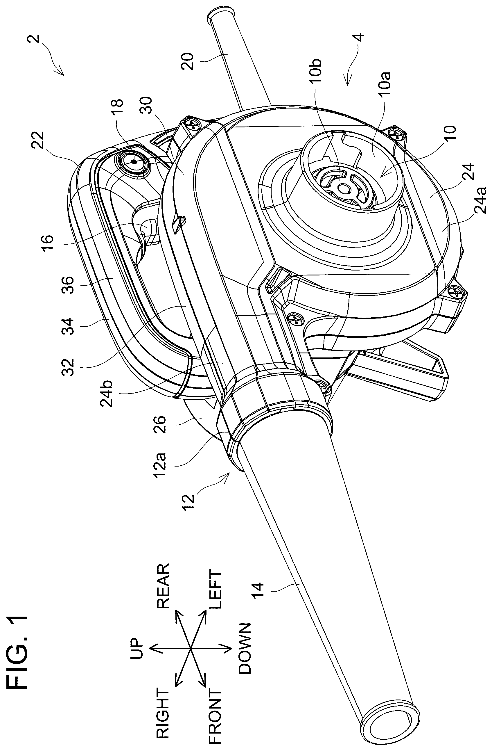
illustrates a perspective view of a blower 2 according to an embodiment.
illustrates a cross-sectional view of the blower 2 according to the embodiment.
illustrates a side view showing an inside of a fan case 24 in the blower 2 according to the embodiment.
illustrates a perspective view of an exhaust port 12 and its surroundings of the blower 2 according to the embodiment.
illustrates a cross-sectional view of the exhaust port 12 and its surroundings in the blower 2 according to the embodiment.
illustrates a longitudinal-sectional view of the exhaust port 12 and its surroundings in the blower 2 according to the embodiment.
shows a graph showing a relation between a motor rotation speed and a noise level with respect to the blower 2 according to the embodiment and a blower 2 according to a comparative example.
illustrates a cross-sectional view of an exhaust port 12 and its surroundings of a blower 2 according to a modification.
illustrates a cross-sectional view of an exhaust port 12 and its surroundings of a blower 2 according to another modification.
illustrates a cross-sectional view of an exhaust port 12 and its surroundings of a blower 2 according to yet another modification.
DESCRIPTION
Representative, non-limiting examples of the present disclosure will now be described in further detail with reference to the attached drawings. This detailed description is merely intended to teach a person of skill in the art further details for practicing preferred aspects of the present teachings and is not intended to limit the scope of the disclosure. Furthermore, each of the additional features and teachings disclosed below may be utilized separately or in conjunction with other features and teachings to provide improved blowers, as well as methods for using and manufacturing the same.
Moreover, combinations of features and steps disclosed in the following detailed description may not be necessary to practice the disclosure in the broadest sense, and are instead taught merely to particularly describe representative examples of the disclosure. Furthermore, various features of the above-described and below-described representative examples, as well as the various independent and dependent claims, may be combined in ways that are not specifically and explicitly enumerated in order to provide additional useful embodiments of the present teachings.
All features disclosed in the description and/or the claims are intended to be disclosed separately and independently from each other for the purpose of original written disclosure, as well as for the purpose of restricting the claimed subject matter, independent of the compositions of the features in the embodiments and/or the claims. In addition, all value ranges or indications of groups of entities are intended to disclose every possible intermediate value or intermediate entity for the purpose of original written disclosure, as well as for the purpose of restricting the claimed subject matter.
In one or more embodiments, with respect to the direction blocking the airflow, a height of the protrusion may be within a range of 1% to 50% of a thickness of the plate portion.
According to the above configuration, periodical generation of vortex flow can be suppressed without greatly affecting an air volume of the blower.
In one or more embodiments, with respect to the direction in which the airflow flows, a width of the protrusion may be within a range of 1% to 50% of a minimum width of the plate portion.
According to the above configuration, without greatly affecting the air volume of the blower, periodical generation of vortex flow can be suppressed.
In one or more embodiments, the protrusion may comprise a plurality of protrusions, and the protrusions may be arranged intermittently.
According to the above configuration, as compared to a case where the protrusion is continuously disposed, an effect thereof imposed on the air volume of the blower can be mitigated.
In one or more embodiments, the protrusion may be arranged continuously.
According to the above configuration, when the plate portion including the protrusion is produced by integral molding of a resin material, workability in releasing the plate portion from a mold can be improved.
In one or more embodiments, the protrusion may be arranged only on one of the side surfaces of the plate portion, and the protrusion may not be arranged on the other of the side surfaces of the plate portion.
According to the above configuration, as compared to a case where the protrusions are disposed on both of the side surfaces of the plate portion, an effect thereof imposed on the air volume of the blower can be mitigated.
In one or more embodiments, the prime mover may be an electric motor.
When the electric motor is used as the prime mover, it is more quiet when the electric motor operates than when an internal engine is used as the prime mover. As such, if loud noise is generated in using the electric motor, user comfort would be greatly impaired. According to the above configuration, in the blower which uses the electric motor as the prime mover, generation of loud noise can be suppressed.
EMBODIMENT
A blower 2 shown in comprises a housing 4 , a fan 6 (see ), an electric motor 8 (see ), a suction port 10 , an exhaust port 12 , a nozzle 14 , a trigger switch 16 , a lock button 18 , and a power cable 20 . The blower 2 is a hand-held work machine configured to be held and used by a user with one hand. The nozzle 14 is configured to be detachably attached selectively to either the suction port 10 or the exhaust port 12 , depending on which work the blower 2 is used for. For example, by using the blower 2 with the nozzle 14 attached to the exhaust port 12 , the blower 2 can perform a blowing work of blowing air from a tip of the nozzle 14 to blow away leaves on a ground, for example. Also, by using the blower 2 with the nozzle 14 attached to the suction port 10 and a dust bag (not illustrated) attached to the exhaust port 12 , the blower 2 can perform a suctioning work of suctioning air from the tip of the nozzle 14 to collect dust, for example, into the dust bag. Here, in the following description, a direction in which air flows at the exhaust port 12 will be referred to as “front/frontward” while a direction opposite from the front direction will be referred to as “rear/rearward”. Also, a direction in which air flows at the suction port 10 will be referred to as “right/rightward” while a direction opposite from right will be referred to as “left/leftward”. Further, a direction orthogonal both to a front-rear direction and a left-right direction will be referred to as an “up-down direction”.
As illustrated in , the housing 4 comprises a handle 22 configured to be grasped by the user, a fan case 24 configured to accommodate the fan 6 , and a motor case 26 configured to accommodate the electric motor 8 . The trigger switch 16 and the lock button 18 are disposed on the handle 22 . Also, the power cable 20 (see ) is connected to the handle 22 . When the user pulls the trigger switch 16 inward and thus the trigger switch 16 is turned on, electric power is supplied from the power cable 20 to the electric motor 8 , by which the fan 6 rotates. At this occasion, a rotation speed of the electric motor 8 varies according to a degree at which the trigger switch 16 is pulled. When the user has his/her hand released from the trigger switch 16 and thus the trigger switch 16 is turned off, the supply of electric power from the power cable 20 to the electric motor 8 is cut off, by which the fan 6 stops rotating. When the user further pushes the lock button 18 in a state of having pulled the trigger switch 16 , the trigger switch 16 remains in the state of being pulled even if the user subsequently releases his/her hand from the lock button 18 and/or the trigger switch 16 . In this case, the electric motor 8 is maintained in a state of rotating at a designated rotation speed.
The suction port 10 communicates inside and outside of the fan case 24 . The suction port 10 comprises a nozzle receiving portion 10 a having a cylindrical shape and protruding leftward, and a filter portion 10 b configured to suppress entry of foreign matter/object into the fan case 24 . The suction port 10 is disposed substantially coaxial with a rotation axis of the fan 6 inside the fan case 24 . The fan case 24 and the motor case 26 are in communication with each other through a motor exhaust port 28 . Also, a right end of the motor case 26 comprises a motor suction port (not illustrated) which communicates with inside and outside of the motor case 26 .
The fan 6 comprises a base 6 a having a circular plate shape, a first fan 6 b protruding leftward from a left surface of the base 6 a , and a second fan 6 c protruding rightward from a right surface of the base 6 a . Each of the first fan 6 b and the second fan 6 c functions as a centrifugal fan. As illustrated in , the fan case 24 comprises a volute portion 24 a having a volute shape and a straight tube portion 24 b having a straight tube shape. As illustrated in , when the fan 6 rotates, air is suctioned from the suction port 10 into the volute portion 24 a of the fan case 24 , and the air is pushed outward from inside to outside in a radial direction of the first fan 6 b . Also, when the fan 6 rotates, the second fan 6 c suctions air from the motor exhaust port 28 into the volute portion 24 a of the fan case 24 , and the air is pushed from inside to outside of the radial direction of the second fan 6 c . At this occasion, air is suctioned from the motor suction port into the motor case 26 , and the air within the motor case 26 flows from the motor exhaust port 28 into the fan case 24 , and this airflow within the motor case 26 causes the electric motor 8 to be cooled. As illustrated in , the air, which is pushed outward from inside to outside in the radial direction due to the rotation of the first fan 6 b and the second fan 6 c , flows along an inner surface of the volute portion 24 a on the outside in the radial direction, flows through the straight tube portion 24 b , and then is fed frontward from the exhaust port 12 .
As illustrated in , the housing 4 comprises a left-side housing 30 defining a left-side portion of the fan case 24 , a middle housing 32 defining a right-side portion of the fan case 24 and a left-side portion of the motor case 26 , a right-side housing 34 defining a right-side portion of the motor case 26 and a right-side portion of the handle 22 , and a handle housing 36 defining a left-side portion of the handle 22 .
As illustrated in , the exhaust port 12 is disposed at a downstream end (i.e., front end) of the straight tube portion 24 b . The exhaust port 12 comprises a nozzle receiving portion 12 a having a cylindrical shape and protruding frontward and a filter portion 12 b configured to suppress entry of foreign matter/object into the fan case 24 . In the present embodiment, the filter portion 12 b is composed of a plurality of plate portions 38 . The plate portions 38 all have a substantially plate shape extending along the front-rear direction and the left-right direction. The plurality of plate portions 38 comprises a first right plate portion 38 a , a first left plate portion 38 b , a second right plate portion 38 c , a second left plate portion 38 d , a third right plate portion 38 c , and a third left plate portion 38 f . The first right plate portion 38 a , the second right plate portion 38 c , and the third right plate portion 38 e are integrally and seamlessly formed with the middle housing 32 , and each extends leftward from an inner surface of the middle housing 32 . The second right plate portion 38 c is disposed below the first right plate portion 38 a , and the third right plate portion 38 e is disposed below the second right plate portion 38 c . The first left plate portion 38 b , the second left plate portion 38 d , and the third left plate portion 38 f are integrally and seamlessly formed with the left-side housing 30 , and each extends rightward from an inner surface of the left-side housing 30 . The second left plate portion 38 d is disposed below the first left plate portion 38 b , and the third left plate portion 38 f is disposed below the second left plate portion 38 d.
As illustrated in , positions in the up-down direction of the first right plate portion 38 a and the first left plate portion 38 b are substantially equal to each other. A distance D 1 in the up-direction between a highest part of an inner surface of the exhaust port 12 and an upper surface of the first right plate portion 38 a (or upper surface of the first left plate portion 38 b ) is within a range of 2 mm to 12 mm, and is 11 mm, for example. The first right plate portion 38 a and the first left plate portion 38 b have thicknesses in the up-down direction that are substantially equal to each other. A thickness T 1 in the up-down direction of the first right plate portion 38 a (or the first left plate portion 38 b ) is within a range of 0.1 mm to 5 mm, and is 1.5 mm, for example. A right end of the first right plate portion 38 a and a left end of the first left plate portion 38 b are in contact with each other.
Positions in the up-down direction of the second right plate portion 38 c and the second left plate portion 38 d are substantially equal to each other. A distance D 2 between a lower surface of the first right plate portion 38 a (or lower surface of the first left plate portion 38 b ) and an upper surface of the second right plate portion 38 c (or upper surface of the second left plate portion 38 d ) is within a range of 2 mm to 12 mm, and is 11.5 mm, for example. The second right plate portion 38 c and the second left plate portion 38 d have thicknesses in the up-down direction that are substantially equal to each other. A thickness T 2 in the up-down direction of the second right plate portion 38 c (or the second left plate portion 38 d ) is within a range of 0.1 mm to 5 mm, and is 1.5 mm, for example. In the present embodiment, the thickness T 2 in the up-down direction of the second right plate portion 38 c (or the second left plate portion 38 d ) is substantially equal to the thickness T 1 in the up-down direction of the first right plate portion 38 a (or the first left plate portion 38 b ). A right end of the second right plate portion 38 c and a left end of the second left plate portion 38 d are in contact with each other.
Positions in the up-down direction of the third right plate portion 38 e and the third left plate portion 38 f are substantially equal to each other. A distance D 3 in the up-down direction between a lower surface of the second right plate portion 38 c (or lower surface of the second left plate portion 38 d ) and an upper surface of the third right plate portion 38 e (or upper surface of the third left plate portion 38 f ) is within a range of 2 mm to 12 mm, and is 6 mm for example. A distance D 4 in the up-down direction between a lower surface of the third right plate portion 38 c (or lower surface of the third left plate portion 38 f ) and a lowest part of the inner surface of the exhaust port 12 is within a range of 2 mm to 12 mm, and is 6 mm, for example. The third right plate portion 38 c and the third left plate portion 38 f have thicknesses in the up-down direction that are substantially equal to each other. A thickness T 3 in the up-down direction of the third right plate portion 38 c (or the third left plate portion 38 f ) is within a range of 0.5 mm to 5 mm, and is 1.5 mm, for example. In the present embodiment, the thickness T 3 in the up-down direction of the third right plate portion 38 e (or the third left plate portion 38 f ) is substantially equal to the thickness T 2 in the up-down direction of the second right plate portion 38 c (or the second left plate portion 38 d ). A right end of the third right plate portion 38 e and a left end of the third left plate portion 38 f are in contact with each other.
As illustrated in , the first right plate portion 38 a , the second right plate portion 38 c , and the third right plate portion 38 e have a substantially right angle trapezoidal shape in a plan view from above, and in this trapezoid, a front side is substantially perpendicular to a right side and a left side and a length of the right side is longer than a length of the left side. The first left plate portion 38 b , the second left plate portion 38 d , and the third left plate portion 38 f have a substantially right angle trapezoidal shape in the plan view from above, and in this trapezoid, a front side is substantially perpendicular to a right side and a left side and a length of the left side is longer than a length of the right side.
As illustrated in , in the plan view of the first right plate portion 38 a (or the first left plate portion 38 b ) from above, a distance L in the front-rear direction between a crosspoint C of a virtual line extend from a rear side and a virtual line extended from the left side (or right side) and the front side is within a range of 1 mm to 50 mm, and is 13 mm, for example. Also, in the plan view of the first right plate portion 38 a (or the first left plate portion 38 b ) from above, an angle θ formed between the rear side and the left side (or right side) is within a range of 0.1 degrees to 90 degrees, and is 45 degrees, for example. The second right plate portion 38 c (or the second left plate portion 38 d ) and the third right plate portion 38 e (or the third left plate portion 38 f ) also have features that are same as the above-mentioned ones.
As illustrated in , at least a part of the plurality of plate portions 38 comprises a plurality of protrusions 40 . For example, the upper surface of the first right plate portion 38 a comprises a first right-upper protrusion 40 a protruding upward from a vicinity of a front end of the first right plate portion 38 a and extending in the left-right direction. The upper surface of the first left plate portion 38 b comprises a first left-upper protrusion 40 b protruding upward from a vicinity of a front end of the first left plate portion 38 b and extending in the left-right direction. As illustrated in , the first right-upper protrusion 40 a and the first left-upper protrusion 40 b have heights in the up-down direction that are substantially equal to each other. A height H in the up-down direction of the first right-upper protrusion 40 a (or the first left-upper protrusion 40 b ) is within a range of 0.15 mm to 1.5 mm, and is 0.5 mm, for example. As illustrated in , the first right-upper protrusion 40 a and the first left-upper protrusion 40 b have widths in the front-rear direction that are substantially equal to each other. A width W in the front-rear direction of the first right-upper protrusion 40 a (or the first left-upper protrusion 40 b ) is within a range of 0.5 mm to 10 mm, and is 2 mm, for example.
In the present embodiment, the first right-upper protrusion 40 a extends continuously in the left-right direction on the upper surface of the first right plate portion 38 a . Due to this, when the middle housing 32 is fabricated by way of integral molding of resin material, a mold which defines shapes of the first right plate portion 38 a and the first right-upper protrusion 40 a can be simply moved linearly leftward to enable the middle housing 32 to be released from the mold. Also, the first left-upper protrusion 40 b extends continuously in the left-right direction on the upper surface of the first left plate portion 38 b . Due to this, when the left-side housing 30 is fabricated by way of integral molding of resin material, a mold which defines shapes of the first left plate portion 38 b and the first left-upper protrusion 40 b can be simply moved linearly rightward to enable the left-side housing 30 to be released from the mold.
is a graph showing the influence of the presence or absence of the first right-upper protrusion 40 a and the first left-upper protrusion 40 b on the noise during use of the blower 2 . A plot of “Without Measures” in shows a noise level during use of the blower 2 when the first right-upper protrusion 40 a and the first left-upper protrusion 40 b are absent. As is apparent from , in this case, the noise during use of the blower 2 is particularly loud at a specific motor rotation speed. This is considered to be because, without the first right-upper protrusion 40 a or the first left-upper protrusion 40 b , vortex flow is periodically generated at the front end of the first right plate portion 38 a and/or the front end of the first left plate portion 38 b , and thus the frequency at which this vortex flow occurs coincides the vibratory resonant frequency of the plurality of plate portions 38 and/or the straight tube portion 24 b or the acoustic resonant frequency of the straight tube portion 24 b , resulting in the plurality of plate portions 38 and/or the straight tube portion 24 b vibrating resonantly, or the straight tube portion 24 b resonating acoustically.
Contrary to this, a plot of “With Measures” in shows a noise level during use of the blower 2 when there are the first right-upper protrusion 40 a and the first left-upper protrusion 40 b . As is apparent from , in this case, the noise during use of the blower 2 is not particularly great at a specific motor rotation speed. This is considered to be because the first right-upper protrusion 40 a and/or the first left-upper protrusion 40 b suppressed periodical generation of vortex flow at the front end of the first right plate portion 38 a and/or the front end of the first left plate portion 38 b , resulting in reduced vibratory resonance of the plurality of plate portions 38 and/or the straight tube portion 24 b or reduced acoustic resonance of the straight tube portion 24 b.
Modifications
The first right plate portion 38 a , the second right plate portion 38 c , and the third right plate portion 38 c may be parts that are separate from the middle housing 32 , and for example may be secured to the middle housing 32 via a fastener and/or adhesive. The first left plate portion 38 b , the second left plate portion 38 d , and the third left plate portion 38 f may be parts that are separate from the left-side housing 30 , and for example may be secured to the middle housing 32 via a fastener and/or adhesive. Each of the first right plate portion 38 a , the first left plate portion 38 b , the second right plate portion 38 c , the second left plate portion 38 d , the third right plate portion 38 e , and the third left plate portion 38 f may have a shape different from that of the above embodiment. The right end of the first right plate portion 38 a and the left end of the first left plate portion 38 b may not be in contact with each other. The right end of the second right plate portion 38 c and the left end of the second left plate portion 38 d may not be in contact with each other. The right end of the third right plate portion 38 e and the left end of the third left plate portion 38 f may not be in contact with each other.
The first right-upper protrusion 40 a may be consist of a part separate from the first right plate portion 38 a , and may be secured to the first right plate portion 38 a with a fastener and/or adhesive. The first left-upper protrusion 40 b may be consist of a part separate from the first left plate portion 38 b , and may be secured to the first left plate portion 38 b with a fastener and/or adhesive.
The first right-upper protrusion 40 a (or the first left-upper protrusion 40 b ) may be disposed apart from the front end of the first right plate portion 38 a (or the first left plate portion 38 b ), and for example may be disposed within a range from the front end to a spot a predetermined distance (such as 5 mm) away from the front end in the front-rear direction. Further, in a plan view of the first right plate portion 38 a (or the first left plate portion 38 b ) from above, a direction in which the first right-upper protrusion 40 a (or the first left-upper protrusion 40 b ) extends may be inclined with respect to the left-right direction.
As illustrated in , each of the first right-upper protrusion 40 a and the first left-upper protrusion 40 b may not be arranged continuously in the left-right direction, but may comprise a plurality of protrusions, and the protrusions may be arranged intermittently.
As illustrated in , the protrusions 40 may be disposed on plate portions 38 also other than the first right plate portion 38 a and the first left plate portion 38 b . In an example shown in , in addition to the example shown in , the upper surface of the second right plate portion 38 c comprises a second right-upper protrusion 40 c , and the upper surface of the second left plate portion 38 d comprises a second left-upper protrusion 40 d . Positions and/or shapes of the second right-upper protrusion 40 c and the second left-upper protrusion 40 d may be substantially same as or may differ from the positions and/or shapes of the first right-upper protrusion 40 a and the first left-upper protrusion 40 b.
As illustrated in , the protrusions 40 may be disposed on the lower surfaces of the plate portions 38 . In an example shown in , in addition to the example shown in , the upper surface of the third right plate portion 38 e comprises a third right-upper protrusion 40 c , and the upper surface of the third left plate portion 38 f comprises a third left-upper protrusion 40 f . Also, the lower surface of the first right plate portion 38 a comprises a first right-lower protrusion 40 g , and the lower surface of the first left plate portion 38 b comprises a first left-lower protrusion 40 h . The lower surface of the second right plate portion 38 c comprises a second right-lower protrusion 40 i , and the lower surface of the second left plate portion 38 d comprises a second left-lower protrusion 40 j . The lower surface of the third right plate portion 38 e comprises a third right-lower protrusion 40 k , and the lower surface of the third left plate portion 38 f comprises a third left-lower protrusion 40 l.
The number of the plurality of plate portions 38 may be more or fewer than the one of the above-described embodiment.
The blower 2 may comprise an axial fan (not illustrated) or a mixed flow fan (not illustrated), instead of the fan 6 .
As a prime mover configured to rotate the fan 6 , the blower 2 may comprise an internal engine (not illustrated), instead of the electric motor 8 . Alternatively, the blower 2 may comprise another type of electric motor (not illustrated) such as a brushless motor, instead of the electric motor 8 .
The blower 2 may comprise, instead of the power cable 20 , a battery receptacle (not illustrated) configured to have a rechargeable battery pack (not illustrated) detachably attached thereto. In this case, the electric motor 8 may operate on electric power supplied from the battery pack.
Features of Embodiment
As mentioned above, in one or more embodiments, the blower 2 comprises: the electric motor 8 (example for a prime mover); the fan 6 configured to be driven by the electric motor 8 ; the straight tube portion 24 b (example for a blower duct) through which an airflow generated by the fan 6 flows; the plate portions 38 disposed inside the straight tube portion 24 b and having side surfaces extending along a direction in which the airflow flows; and the protrusions 40 protruding from the side surfaces near the downstream ends of the plate portions 38 in a direction blocking the airflow.
According to the above configuration, since the protrusions 40 are disposed near the downstream ends of the plate portions 38 , periodical generation of vortex flow can be suppressed at the downstream ends of the plate portions 38 . Due to this, the vibratory resonance of the plate portions 38 and/or straight tube portion 24 b or the acoustic resonance of the straight tube portion 24 b can be suppressed, by which generation of loud noise can also be suppressed.
In one or more embodiments, with respect to the direction blocking the airflow, a height of the protrusions 40 is within a range of 1% to 50% of the thickness of the plate portions 38 .
According to the above configuration, periodical generation of vortex flow can be suppressed without greatly affecting an air volume of the blower 2 .
In one or more embodiments, with respect to the direction in which the airflow flows, a width of the protrusions 40 is within a range of 1% to 50% of a minimum width of the plate portions 38 .
According to the above configuration, without greatly affecting the air volume of the blower 2 , periodical generation of vortex flow can be suppressed.
In one or more embodiments, the protrusions 40 are arranged intermittently.
According to the above configuration, as compared to a case where each of the protrusions 40 is continuously disposed, an effect thereof imposed on the air volume of the blower 2 can be mitigated.
In one or more embodiments, each of the protrusions 40 may be arranged continuously.
According to the above configuration, when the plate portions 38 including the protrusions 40 are produced by integral molding of a resin material, workability in releasing of the plate portions 38 from a mold can be improved.
In one or more embodiments, the protrusions 40 are arranged only on one (e.g., upper surface) of the side surfaces of the plate portion(s) 38 , and the protrusions 40 are not arranged on the other (e.g., lower surface) of the side surfaces of the plate portion(s) 38 .
According to the above configuration, as compared to a case where the protrusions 40 are disposed on both surfaces of the plate portion(s) 38 , an effect thereof imposed on the air volume of the blower 2 can be mitigated.
In one or more embodiments, the electric motor 8 functions as a prime mover configured to drive the fan 6 .
When the electric motor 8 is used as the prime mover, it is more quiet when the electric motor 8 operates than when an internal engine (not illustrated) is used as the prime mover. As such, if loud noise is generated in using the electric motor 8 , user comfort would be greatly impaired. According to the above configuration, in the blower 2 which uses the electric motor 8 as the prime mover, generation of loud noise can be suppressed.
Figures (10)
Citations
This patent cites (7)
- US9011092
- US10088194
- US10323853
- US10570928
- US11965523
- US2016/0309661
- US2022-123186