Label Affixing Device Including Peeling Part Peeling Label Off Release Material, Affixing Part Affixing Label to Adherend, and Discharge Part Through Which Release Material Is Discharged
Abstract
A label affixing device includes a first conveying part, a peeling part, an affixing part, a discharge part, and a conveying guide. The first conveying part is configured to convey a tape including a label and a release material affixed thereto. The peeling part is configured to peel the label off the release material. The affixing part is configured to affix the peeled label to an adherend and is disposed downstream relative to the peeling part in a conveying direction of the label. The release material from which the label has been peeled off is discharged through the discharge part. The discharge part is disposed downstream relative to the peeling part in a conveying direction of the release material. The conveying guide is switchable between a first position for guiding the tape toward the discharge part and a second position for guiding the peeled label toward the affixing part.
Claims (28)
1 . A label affixing device comprising: a first conveying part configured to convey a tape from an upstream side toward a downstream side, the tape including a label and a release material affixed to the label; a peeling part configured to peel the label off the release material, the peeling part being disposed further downstream than the first conveying part in a conveying direction of the tape; an affixing part configured to affix the label peeled off the release material by the peeling part to an adherend, the affixing part being disposed downstream relative to the peeling part in a conveying direction of the label; a discharge part through which the release material from which the label has been peeled off by the peeling part is discharged, the discharge part being disposed downstream relative to the peeling part in a conveying direction of the release material; a conveying guide switchable between: a first position in which the conveying guide guides the tape toward the discharge part; and a second position in which the conveying guide guides the label peeled off the release material by the peeling part toward the affixing part; and a drive mechanism configured to move the conveying guide between the first position and the second position.
Show 27 dependent claims
2 . The label affixing device according to claim 1 , wherein the peeling part and the conveying guide move in conjunction with each other, wherein the peeling part does not peel the label off the release material in a state where the conveying guide is disposed in the first position, and wherein the peeling part peels the label off the release material in a state where the conveying guide is disposed in the second position.
3 . The label affixing device according to claim 1 , further comprising: a third conveying part configured to convey: the tape; or the release material from which the label has been peeled off by the peeling part.
4 . The label affixing device according to claim 3 , wherein a conveying speed at which the tape or the release material is conveyed by the third conveying part is greater than a conveying speed at which the tape is conveyed by the first conveying part.
5 . The label affixing device according to claim 3 , wherein the third conveying part includes a third roller, wherein the label affixing device further comprises: a plurality of third auxiliary rollers adjacent to each other in a direction orthogonal to a conveying direction in which the tape or the release material is conveyed, the plurality of third auxiliary rollers being configured to nip, in cooperation with the third roller, the tape or the release material between the plurality of third auxiliary rollers and the third roller, and wherein at least part of the conveying guide disposed in the first position is arranged between the plurality of third auxiliary rollers in the direction orthogonal to the conveying direction in which the tape or the release material is conveyed.
6 . The label affixing device according to claim 1 , wherein the first conveying part includes a first roller, wherein the label affixing device further comprises: a fourth roller opposing the first roller with a conveying path of the tape interposed between the fourth roller and the first roller; and a first cover configured to be opened and closed between: a state where a conveying path through which the label peeled off the release material by the peeling part passes is exposed; and a state where the conveying path through which the label peeled off the release material by the peeling part passes is not exposed, wherein the fourth roller nips the tape while the first cover is closed, and wherein the fourth roller is separated from the tape while the first cover is open.
7 . The label affixing device according to claim 1 , wherein the conveying guide has a first curved portion formed at a portion of the conveying guide which faces the peeling part, wherein the label affixing device further comprises: a guide portion provided on a conveying path of the tape guided by the conveying guide disposed in the first position, the guide portion being configured to guide the tape along the conveying path of the tape, wherein the guide portion has a second curved portion, wherein the first curved portion is positioned further upstream than an upstream end portion of the guide portion in the conveying direction of the tape, and wherein a radius of curvature of the first curved portion is smaller than a radius of curvature of the second curved portion.
8 . The label affixing device according to claim 1 , further comprising: a plurality of conveying spurs configured to guide the label peeled off the release material by the peeling part, wherein the conveying guide has at least one protruding portion configured to pass between the plurality of conveying spurs during the course of movement of the conveying guide between the first position and the second position.
9 . The label affixing device according to claim 1 , wherein the conveying guide disposed in the second position is separated from a conveying path of the label peeled off the release material by the peeling part.
10 . The label affixing device according to claim 1 , further comprising: a printing unit configured to print on a portion of the tape, wherein the first conveying part is configured to convey the tape printed by the printing unit.
11 . The label affixing device according to claim 2 , further comprising: a retaining part retaining the conveying guide and the peeling part from both sides in a width direction of the label, wherein, in accordance with movement of the retaining part, the conveying guide and the peeling part move in conjunction with each other.
12 . The label affixing device according to claim 11 , wherein the retaining part is pivotally movable, wherein, in accordance with pivotal movement of the retaining part, the conveying guide moves between the first position and the second position, and wherein a rotating direction of the retaining part when a weight of the peeling part acts on the retaining part in a state where the conveying guide is disposed in the second position is opposite a rotating direction of the retaining part when the conveying guide moves from the second position to the first position.
13 . The label affixing device according to claim 11 , further comprising: a frame supporting the retaining part so that the retaining part is pivotally movable; and a pin configured to be inserted through the retaining part to restrict pivotal movement of the retaining part.
14 . The label affixing device according to claim 1 , wherein the drive mechanism includes a pair of driving parts configured to move end portions of the conveying guide, the end portions being both end portions of the conveying guide in a width direction of the label.
15 . The label affixing device according to claim 1 , further comprising: a retaining part retaining the conveying guide, the retaining part having an elongated hole, wherein the conveying guide is configured to move between the first position and the second position by rotating about a rotational shaft, wherein the drive mechanism includes a cam provided with an inserted part inserted into the elongated hole of the retaining part, wherein rotation of the cam causes the conveying guide to move between the first position and the second position, and wherein both in a state where the conveying guide is disposed in the first position and in a state where the conveying guide is disposed in the second position, the inserted part is disposed at either of both end portions of the elongated hole.
16 . The label affixing device according to claim 15 , wherein a position of the inserted part when the conveying guide is disposed in the first position, a position of the inserted part when the conveying guide is disposed in the second position, and a rotational center of the cam are arranged in a circumferential direction about the rotational shaft of the conveying guide.
17 . The label affixing device according to claim 3 , wherein the third conveying part includes a third roller, wherein the label affixing device further comprises a transmission unit configured to transmit a rotational drive force to the third roller, and wherein the transmission unit prohibits transmission of the rotational drive force to the third roller during movement of the conveying guide between the first position and the second position.
18 . The label affixing device according to claim 1 , further comprising: a conveying motor configured to drive at least the first conveying part; and a moving motor configured to move the conveying guide between the first position and the second position, wherein the conveying motor and the moving motor are positioned on the same side of a virtual plane passing through a conveying path of the label.
19 . The label affixing device according to claim 1 , further comprising: a printing unit configured to print on a portion of the tape, wherein the first conveying part is configured to convey the tape printed by the printing unit, and wherein the label affixing device further comprises: a controller configured to perform: starting printing by the printing unit in a state where the conveying guide is disposed in the first position.
20 . The label affixing device according to claim 19 , wherein the controller is configured to further perform: placing the conveying guide in the first position in a ready state before starting printing.
21 . The label affixing device according to claim 20 , wherein the ready state is a state before the tape is attached.
22 . The label affixing device according to claim 19 , wherein the controller is configured to further perform: switching the conveying guide from the first position to the second position at a time within a period of time from a time when the first conveying part starts conveying the tape to a time when an edge of the label of the tape being conveyed has reached the peeling part, the edge of the label being an upstream edge of the label in the conveying direction of the tape.
23 . The label affixing device according to claim 22 , further comprising: a second conveying part configured to convey the label peeled off the release material by the peeling part toward the affixing part; and a third conveying part configured to convey the tape or the release material from which the label has been peeled off by the peeling part, wherein the controller is configured to further perform: conveyance of the label by the second conveying part without performing conveyance of the release material by the third conveying part when an upstream edge of the label in the conveying direction of the label has moved to a downstream side of the peeling part in the conveying direction of the label by the label peeled off the release material by the peeling part being guided by the conveying guide disposed in the second position.
24 . The label affixing device according to claim 19 , wherein the controller is configured to further perform: conveying the tape toward the discharge part using the first conveying part in a state where the conveying guide is disposed in the first position.
25 . The label affixing device according to claim 24 , further comprising: a third conveying part configured to convey the tape or the release material from which the label has been peeled off by the peeling part, wherein the controller is configured to further perform: receiving an instruction for replacement of the tape; and cutting the tape using a cutting unit when the controller receives the instruction, the cutting unit being disposed further upstream than the peeling part in the conveying direction of the tape, wherein, after cutting the tape, the controller conveys the cut tape using the third conveying part until an upstream edge of the cut tape in the conveying direction of the tape has moved to a downstream side of the third conveying part.
26 . The label affixing device according to claim 25 , wherein, when a first sensor disposed further downstream than the third conveying part in the conveying direction of the tape has detected a cut portion of the cut tape after the start of conveyance of the cut tape by the third conveying part, the controller halts the conveyance of the tape by the first conveying part and the third conveying part.
27 . The label affixing device according to claim 24 , wherein the controller is configured to further perform: detecting an operational failure or a printing failure; and printing, when the controller has detected an operational failure or a printing failure, an image using the printing unit that is the same as an image printed before the detection of the operational failure or the printing failure.
28 . The label affixing device according to claim 27 , further comprising: a second sensor configured to detect a presence or absence of the label, the second sensor being disposed further downstream than the peeling part in the conveying direction of the label, wherein the controller detects an operational failure related to a label jamming at the peeling part when the second sensor has not detected the label peeled off the release material by the peeling part for a prescribed period of time or greater since peeling of the label off the release material, and wherein the controller detects an operational failure related to a label jamming at the affixing part when the second sensor has continuously detected the label for a prescribed period of time or greater since the start of the detection of the label by the second sensor.
Full Description
Show full text →
REFERENCE TO RELATED APPLICATIONS
This is a by-pass continuation application of International Application No. PCT/JP2022/027081 filed on Jul. 8, 2022 claiming priority from Japanese Patent Application No. 2021-126147 filed on Jul. 30, 2021. The entire contents of the International Application and the priority application are incorporated herein by reference.
BACKGROUND ART
There are known devices for affixing labels to adherends. Japanese Patent Application Publication No. 2020-63087 discloses a label printing device. The label printing device prints on label paper a description of items matching the contents of a package and subsequently peels the printed label paper off the backing paper with a peeling roller. The label printing device cuts the printed label paper peeled off the backing paper in conformance with the printed area. With a guide belt, the label printing device conveys the printed and cut label paper toward a conveyor. The label printing device affixes the printed label paper conveyed by the guide belt to a package conveyed by the conveyor.
SUMMARY
In order to attach a label roll to the label printing device to make the label printing device in a usable state, the user must pull the label paper and backing paper off the label roll and guide them to the peeling roller. Thus, a label affixing device that affixes labels after peeling the labels from a release material is problematic in that attachment of tape including labels and release material to the label affixing device requires time and effort.
In view of the foregoing, it is an object of the present disclosure to provide a label affixing device to which tape including a label and release material can be easily attached.
In order to attain the above and other objects, according to one aspect, the present disclosure provides a label affixing device including a first conveying part, a peeling part, an affixing part, a discharge part, and a conveying guide. The first conveying part is configured to convey a tape from an upstream side toward a downstream side. The tape includes a label and a release material affixed to the label. The peeling part is configured to peel the label off the release material. The peeling part is disposed further downstream than the first conveying part in a conveying direction of the tape. The affixing part is configured to affix the label peeled off the release material by the peeling part to an adherend. The affixing part is disposed downstream relative to the peeling part in a conveying direction of the label. The release material from which the label has been peeled off by the peeling part is discharged through the discharge part. The discharge part is disposed downstream relative to the peeling part in a conveying direction of the release material. The conveying guide is switchable between a first position and a second position. In the first position, the conveying guide guides the tape toward the discharge part. In the second position, the conveying guide guides the label peeled off the release material by the peeling part toward the affixing part.
BRIEF DESCRIPTION OF DRAWINGS
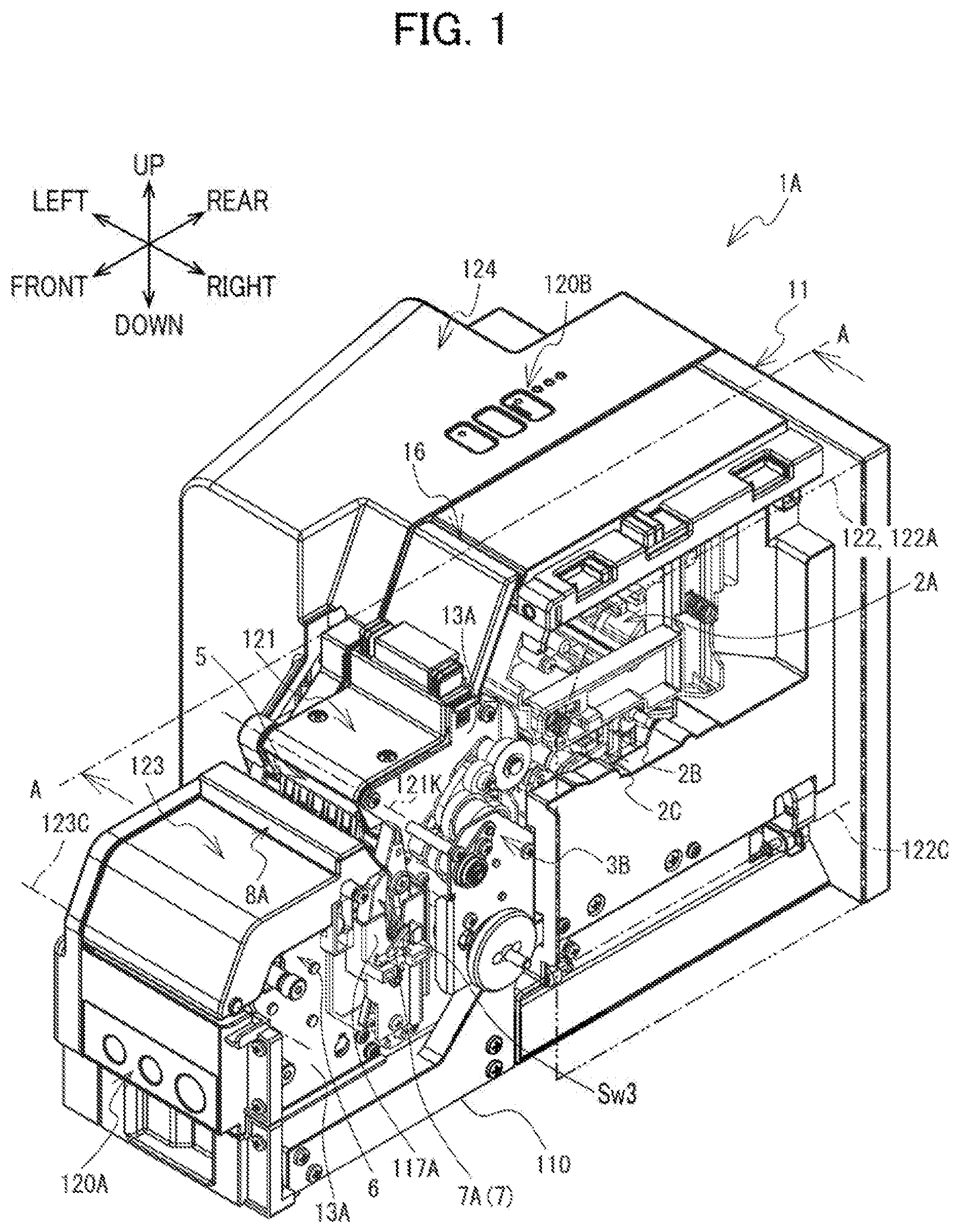
is a perspective view of a label wrapping device 1 A.
is a perspective view of the label wrapping device 1 A (a third cover 123 : open).
is a perspective view of the label wrapping device 1 A (a first cover 121 : open; a fourth cover 124 : omitted).
is a plan view of the label wrapping device 1 A (the first cover 121 : open).
is a perspective view of the label wrapping device 1 A divided by line A-A in .
is a cross-sectional view taken along line A-A in as viewed in a direction indicated by the arrows in .
is an enlarged view of an area within frame border W 1 in .
is an enlarged view of an area within frame border W 2 in .
is a perspective view of a peeling and guiding mechanism 4 (a second position).
is a cross-sectional view of the periphery of a first roller 301 , a second roller 302 , and a fourth roller 304 (a nipping position).
is a cross sectional view of the peeling guiding mechanism 4 (a first position), the first roller 301 , and the fourth roller 304 (a separated position).
is a perspective view of the peeling and guiding mechanism 4 (the first position).
is a cross-sectional view of the periphery of the first roller 301 , the second roller 302 , and the fourth roller 304 (the separated position).
is a cross-sectional view of the peeling and guiding mechanism 4 (the first position), the first roller 301 , and the fourth roller 304 (the nipping position).
is an enlarged perspective view of the periphery of follow rollers 311 through 313 .
is a perspective view of a transmission unit 3 B (a link mechanism 38 : a contact position).
is a right side view of the transmission unit 3 B (a motor Mw 2 : forward rotation; the link mechanism 38 : the contact position).
is a right side view of the transmission unit 3 B (the motor Mw 2 : reverse rotation; the link mechanism 38 : the contact position).
is a perspective view of the peeling and guiding mechanism 4 (the second position) and the link mechanism 38 (the contact position).
is a perspective view of the peeling and guiding mechanism 4 (an intermediate position) and the link mechanism 38 (a separation position).
is a perspective view of the peeling and guiding mechanism 4 (the first position) and the link mechanism 38 (the contact position).
is a right side view of the transmission unit 3 B (the link mechanism 38 : the separation position).
is an enlarged view of an area within frame border W 3 in .
is a perspective view of the periphery of an opening and closing member 5 (a closed position).
is a perspective view of the periphery of the opening and closing member 5 (an open position).
is a cross-sectional view of the periphery of an affixing mechanism 6 (the opening and closing member 5 : the closed position) taken along line A-A in as viewed in the direction indicated by the arrows in .
is a cross-sectional view of the periphery of the affixing mechanism 6 (the opening and closing member 5 : the open position) taken along line A-A in as viewed in the direction indicated by the arrows in .
is a perspective view of the periphery of the affixing mechanism 6 divided by line A-A in .
is a cross-sectional view of the periphery of the affixing mechanism 6 (the opening and closing member 5 : the open position) taken along the line A-A in as viewed in the direction indicated by the arrows in .
is a right side view of the periphery of a retaining member 7 A (an adjacent position).
is a view illustrating a state in which a cover 117 A is omitted from .
is a cross-sectional view of the retaining member 7 A in the state of .
is a right side view of the periphery of the retaining member 7 A (a separated position) in a state in which the cover 117 is omitted.
is a perspective view of the retaining member 7 (the adjacent position).
is a perspective view of the retaining member 7 (the separated position).
is a view for explaining the operations of first nipping members 71 and the opening and closing member 5 (the open state) when a cable 19 is inserted into insertion parts 62 A.
is a view for explaining the operations of the first nipping members 71 and the opening and closing member 5 (the closed state) when the cable 19 is inserted into the insertion parts 62 A.
is a block diagram illustrating the electrical configuration of the label wrapping device 1 A.
is a flowchart illustrating a tape attachment process.
is a flowchart illustrating a main process.
is a flowchart illustrating the continuation of the main process in .
is a flowchart illustrating a wrapping process.
A through 43 F are diagrams illustrating how a label 10 A is wrapped around a cable 19 .
is a flowchart illustrating a tape replacement process.
is a flowchart illustrating an operational failure process.
DESCRIPTION
A label wrapping device 1 A according to one embodiment of the present disclosure will be described while referring to the drawings. The referenced drawings are used to describe the technical features that can be employed in the present disclosure, and the configurations and the like of the described apparatuses are merely illustrative examples and are not intended to be limited thereto. The label wrapping device 1 A is a device for producing a label 10 A by printing on tape 10 in a tape cassette TC and for wrapping the produced label 10 A around and affixing the produced label 10 A to a cable 19 . Below, the lower-left direction, upper-right direction, upper-left direction, lower-right direction, upward direction, and downward direction in are respectively defined as the frontward direction, rearward direction, leftward direction, rightward direction, upward direction, and downward direction of the label wrapping device 1 A.
Overview of the Label Wrapping Device 1 A
An overview of the label wrapping device 1 A will be described with reference to through 6 . The label wrapping device 1 A has a box-shaped housing 11 . The housing 11 accommodates a frame 13 (see ), which includes side plates 13 A and 13 B that oppose each other in the left-right direction, and a frame 14 (see ). The frame 13 supports a conveying mechanism 3 A (a first roller 301 , a second roller 302 , and a third roller 303 ), a transmission unit 3 B, a peeling and guiding mechanism 4 , an opening and closing member 5 , an affixing mechanism 6 , a retaining member 7 , and the like. The frame 14 is disposed rearward relative to the frame 13 and supports a printing unit 2 B, and a cutting unit 2 C.
As shown in , the bottom surface of the housing 11 forms an installation surface 110 that opposes a table or the like in a state where the housing 11 is placed on the table or the like. The installation surface 110 has a flat shape and extends horizontally. The label wrapping device 1 A is used while the installation surface 110 of the housing 11 is placed on a table or the like.
As shown in , a tape accommodating unit 2 A, the printing unit 2 B, and the cutting unit 2 C are provided in the portion of the housing 11 which is rearward of the front-rear center of the housing 11 . The tape cassette TC (see ) is attachably and detachably accommodated in the tape accommodating unit 2 A. The tape cassette TC is a laminated-type tape cassette. A second cover 122 is provided on the right end portion of the housing 11 so as to be pivotally movable. The pivot center 122 C of the second cover 122 extends in the front-rear direction. The second cover 122 can open and close the tape accommodating unit 2 A. The second cover 122 in a closed state is depicted by two-dot-dash lines in . In this state, the tape accommodating unit 2 A, printing unit 2 B, and cutting unit 2 C are covered by the second cover 122 and not exposed. On the other hand, the tape accommodating unit 2 A, printing unit 2 B, and cutting unit 2 C are exposed when the second cover 122 is placed in an open state. The opening formed when the second cover 122 is placed in the open state will be called a second opening 122 A. The second opening 122 A opens rightward.
A label 10 A, which is produced by printing on the tape 10 with the printing unit 2 B and cutting the tape 10 with the cutting unit 2 C, is peeled off a release material 10 B by the peeling and guiding mechanism 4 (see ). After being peeled off the release material 10 B, the label 10 A passes through a passage area 300 A in the housing 11 and is guided toward a guide member 8 A and the affixing mechanism 6 . In the meantime, the release material 10 B from which the label 10 A has been peeled passes through a passage area 300 B in the housing 11 and is discharged through a discharge part 16 provided at the upper end portion of the housing 11 . The passage areas 300 A and 300 B are formed below a first cover 121 of the housing 11 (see ).
As shown in , the first cover 121 is provided frontward relative to the tape accommodating unit 2 A so as to be pivotally movable. The pivot center 121 K of the first cover 121 (see ) extends in the left-right direction. The first cover 121 opens and closes the peeling and guiding mechanism 4 , a conveying path R 2 located in the passage area 300 A, and conveying paths R 3 and R 4 located in the passage area 300 B. More specifically, the first cover 121 opens and closes the peeling and guiding mechanism 4 , the second roller 302 (described later) for conveying the label 10 A along the conveying path R 2 , and the third roller 303 (described later) for conveying the release material 10 B and the tape 10 along the conveying paths R 3 and R 4 . As shown in , the conveying path R 2 is a path through which the label 10 A peeled off the release material 10 B by the peeling and guiding mechanism 4 passes when the label 10 A is conveyed toward the guide member 8 A and affixing mechanism 6 accommodated in the front end portion of the housing 11 . The conveying path R 3 is a path through which the release material 10 B from which the label 10 A has been peeled by the peeling and guiding mechanism 4 passes when the release material 10 B is conveyed toward the discharge part 16 of the housing 11 . As shown in , the conveying path R 4 is a path through which the tape 10 of the tape cassette TC passes when the tape 10 is conveyed intact toward the discharge part 16 .
show the first cover 121 in a closed state. In this state, the peeling and guiding mechanism 4 and the conveying paths R 2 -R 4 are covered by the first cover 121 and not exposed. show the first cover 121 in an open state. In this state, the peeling and guiding mechanism 4 and the conveying paths R 2 -R 4 are exposed. As indicated in , the opening formed when the first cover 121 is opened will be called a first opening 121 S. The first opening 121 S opens upward. The opening direction of the first opening 121 S (upward) differs from the opening direction of the second opening 122 A (rightward; see ).
The label 10 A peeled off the release material 10 B by the peeling and guiding mechanism 4 is wrapped around and affixed to a cable 19 by the affixing mechanism 6 . A third cover 123 is provided at the front end portion of the housing 11 so as to be pivotally movable for opening and closing the affixing mechanism 6 . The pivot center 123 C of the third cover 123 extends in the left-right direction. show the third cover 123 in a closed state. In this state, the affixing mechanism 6 is covered by the third cover 123 and not exposed. shows the third cover 123 in an open state. In this state, the affixing mechanism 6 is exposed. The opening formed when the third cover 123 is opened will be called a third opening. The third opening opens upward. The opening direction of the first opening 121 S (upward) coincides with the opening direction of the third opening (upward; see ).
A fourth cover 124 is attachably and detachably provided on the opposite side of the tape accommodating unit 2 A from the second cover 122 . show a state in which the fourth cover 124 is attached. In this state, a drive unit 9 B that drives the printing unit 2 B and cutting unit 2 C is covered by the fourth cover 124 and not exposed. shows a state in which the fourth cover 124 is detached. In this state, the drive unit 9 B is exposed.
An operation unit 120 A is provided at the front end portion of the housing 11 , i.e., at the downstream end portion of the housing 11 in the conveying direction of the label 10 A being conveyed along the conveying path R 2 . An operation unit 120 B is provided at the upper end portion of the housing 11 , i.e., at the end portion on the opposite side of the housing 11 from the side on which the installation surface 110 is disposed. The operation units 120 A and 120 B are a plurality of pushbuttons for performing input operations on the label wrapping device 1 A.
Printing Unit 2 B
The printing unit 2 B shown in can print using a laminated-type tape cassette TC. As shown in , a thermal head 21 , a platen holder 22 , and other components as the printing unit 2 B are provided in the tape accommodating unit 2 A.
When a tape cassette TC is attached to the tape accommodating unit 2 A, the thermal head 21 is inserted into a head insertion portion of the tape cassette TC. The platen holder 22 is provided in the lower portion of the tape accommodating unit 2 A. The platen holder 22 is supported so as to be pivotally movable about a pivoting shaft 22 C (see ). As shown in , a platen roller 22 A and a tape sub-roller 22 B are supported on the platen holder 22 so as to be rotatable. The platen roller 22 A faces the thermal head 21 . The tape sub-roller 22 B is provided frontward relative to the platen roller 22 A and faces a drive roller Ts of the tape cassette TC. The platen holder 22 is pivotally moved by the drive of a motor Mp 2 (see ) to move between a standby position and a printing position. While the platen holder 22 is in the standby position, the platen roller 22 A is separated from the thermal head 21 . While the platen holder 22 is in the printing position, the platen roller 22 A is adjacent to the thermal head 21 and the tape sub-roller 22 B is adjacent to the drive roller Ts of the tape cassette TC.
As shown in , the tape cassette TC accommodates a first tape 101 , a second tape 103 , and an ink ribbon Ir. The first tape 101 is a transparent film tape formed of polyethylene terephthalate (PET). The second tape 103 is configured of a base material 102 and the release material 10 B which are laminated on each other through adhesive. The first tape 101 and the ink ribbon Ir are paid out from the tape cassette TC with the ink ribbon Ir disposed above the first tape 101 .
When the platen holder 22 moves from the standby position to the printing position, the platen roller 22 A overlays the first tape 101 on the ink ribbon Ir and presses the first tape 101 and the ink ribbon Ir against the thermal head 21 in the overlaid state. The platen roller 22 A rotates and conveys the first tape 101 frontward. At the same time, the thermal head 21 generates heat to heat the ink ribbon Ir. As a result, ink on the ink ribbon Ir is transferred onto the upper surface of the first tape 101 , whereby character information including letters and the like is printed. After printing, the ink ribbon Ir is separated from the first tape 101 and taken up by the tape cassette TC.
Next, the second tape 103 is overlaid on the upper surface of the printed first tape 101 . The base material 102 of the second tape 103 contacts the upper surface of the first tape 101 . In this state, the first tape 101 and second tape 103 pass between the drive roller Ts of the tape cassette TC and the tape sub-roller 22 B. The base material 102 adheres to the upper surface of the first tape 101 , producing a printed label 10 A. The upper surface of the label 10 A corresponds to an adhesive surface Ur of the base material 102 on which adhesive has been deposited, and the release material 10 B is affixed to this adhesive surface Ur. The label 10 A and release material 10 B are referred to as a “tape 10 ”. The width direction of the tape 10 corresponds to the left-right direction. The conveying path of the tape 10 between the printing unit 2 B and the peeling and guiding mechanism 4 described later will be called a “conveying path R 1 ”. The conveying direction of the tape 10 on the conveying path R 1 will be called a “conveying direction Y 1 ”. The conveying direction Y 1 is oriented frontward.
Cutting Unit 2 C
The cutting unit 2 C is disposed downstream in the conveying direction Y 1 relative to the tape sub-roller 22 B of the printing unit 2 B. The cutting unit 2 C has a full-cut cutting blade 23 , and a half-cut cutting blade 24 . The full-cut cutting blade 23 and half-cut cutting blade 24 each have a fixed blade that is fixed above the conveying path R 1 , and a movable blade that is disposed below the conveying path R 1 and is movable. The fixed blades and movable blades extend in the left-right direction. The left end portion of each movable blade is supported on the left side of the conveying path R 1 so as to be pivotally movable relative to the corresponding fixed blade. The right end portions of the movable blades face rightward. The direction in which the right end portions of the movable blades face coincides with the direction in which the second opening 122 A of the second cover 122 opens (see ).
The full-cut cutting blade 23 can divide the tape 10 (i.e., can perform a full-cut) by moving the movable blade relative to the fixed blade. The half-cut cutting blade 24 can cut through just the label 10 A of the tape 10 while leaving the release material 10 B intact (i.e., can perform a half-cut) by moving the movable blade relative to the fixed blade.
First Roller 301
As shown in , the first roller 301 is provided downstream in the conveying direction Y 1 of the tape 10 relative to the cutting unit 2 C (see ) and below the conveying path R 1 . As shown in , the first roller 301 is configured of three cylindrical bodies 301 A, 301 B, and 301 C that are spaced apart from each other in the left-right direction. The cylindrical bodies 301 A, 301 B, and 301 C are aligned in this order from the right side toward the left side. The cylindrical bodies 301 A, 301 B, and 301 C are supported so as to be rotatable about a rotational shaft 301 K extending in the left-right direction. After the tape 10 has been printed by the printing unit 2 B and has passed through the cutting unit 2 C, the first roller 301 conveys the tape 10 downstream in the conveying direction Y 1 toward the peeling and guiding mechanism 4 described later.
As shown in , a fourth roller 304 is disposed above the first roller 301 . As shown in , the fourth roller 304 is configured of three cylindrical bodies that are spaced apart from each other in the left-right direction. The three cylindrical bodies are aligned in order from the right side toward the left side. Each of the three cylindrical bodies faces the corresponding one of the cylindrical bodies 301 A, 301 B, and 301 C of the first roller 301 with the conveying path R 1 (see ) interposed therebetween. The fourth roller 304 is supported by a support member 31 so as to be rotatable about a shaft extending in the left-right direction. The support member 31 is disposed above the first roller 301 .
The fourth roller 304 is supported by the support member 31 so as to be rotatable. The support member 31 has a bent plate shape and is urged upward by springs not shown in the drawings. As shown in , the support member 31 also urges the fourth roller 304 downward by springs 31 A retained on the lower side of the support member 31 .
As shown in , a D-cut shaft 31 B is disposed above the support member 31 . The shaft 31 B extends in the left-right direction and contacts the upper surface of the support member 31 from above. A lever 31 S connected to the left end portion of the shaft 31 B pivotally moves in conjunction with the opening and closing of the first cover 121 (see ). The shaft 31 B rotates in conjunction with the pivotal movement of the lever 31 S.
show the lever 31 S and shaft 31 B when the first cover 121 is in the closed state (see ). As shown in , a curved surface portion 310 B of the shaft 31 B is in contact with the support member 31 , producing the greatest distance between the center of the shaft 31 B and the support member 31 . In this case, the support member 31 is moved downward against the urging force of the springs not shown in the drawings. The fourth roller 304 supported on the support member 31 is adjacent to the first roller 301 . Therefore, when the first cover 121 is in the closed state, the fourth roller 304 and the first roller 301 nip the tape 10 passing through the conveying path R 1 , as shown in . In this case, the tape 10 can be conveyed toward a peeling part 4 A described later by the rotation of the first roller 301 , enabling the peeling part 4 A to peel off the label 10 A. Hereinafter, the position of the fourth roller 304 in this state will be called a “nipping position”.
show the lever 31 S and shaft 31 B when the first cover 121 is in the open state (see ). As shown in , a flat surface portion 310 A of the shaft 31 B is in contact with the support member 31 , producing the shortest distance between the center of the shaft 31 B and the support member 31 . In this case, the support member 31 is moved upward by the urging force of the springs not shown in the drawings. The fourth roller 304 supported on the support member 31 is upwardly separated from the first roller 301 . Therefore, when the first cover 121 is in the open state, the fourth roller 304 is separated from the tape 10 passing through the conveying path R 1 , as shown in . In this case, the tape 10 cannot be conveyed toward the peeling part 4 A even if the first roller 301 rotates, and hence the peeling part 4 A cannot peel off the label 10 A. Hereinafter, the position of the fourth roller 304 in this state will be called a “separated position”.
Peeling and Guiding Mechanism 4
The peeling and guiding mechanism 4 includes the peeling part 4 A, a conveying guide 4 B, a pair of retaining parts 4 C, and a drive mechanism 4 D. As shown in , the peeling part 4 A peels the label 10 A off the release material 10 B. The conveying guide 4 B guides the label 10 A, release material 10 B, and tape 10 in the appropriate conveying direction. The pair of retaining parts 4 C retains the peeling part 4 A and conveying guide 4 B. The drive mechanism 4 D drives the peeling part 4 A, conveying guide 4 B, and pair of retaining parts 4 C.
As shown in , the peeling part 4 A is disposed downstream relative to the first roller 301 in the conveying direction Y 1 of the tape 10 . As shown in , the peeling part 4 A has a slender elongated plate shape that extends in the left-right direction. The edge of the front end portion (hereinafter called the “distal edge portion 400 ”) of the peeling part 4 A is rounded.
As shown in , the conveying guide 4 B is disposed spaced apart from the peeling part 4 A by a prescribed distance. As shown in , the conveying guide 4 B includes a base portion 411 , and a protruding portion 412 . The base portion 411 has a plate shape and is the portion of the conveying guide 4 B that faces the distal edge portion 400 of the peeling part 4 A. A curved portion 41 R that has a concave shape is formed in the surface of the base portion 411 that faces the distal edge portion 400 of the peeling part 4 A. The radius of curvature of the curved portion 41 R will be denoted r 1 . The protruding portion 412 is configured of three protruding pieces 412 A, 412 B, and 412 C that protrude from the front end portion of the base portion 411 . The protruding pieces 412 A, 412 B, and 412 C are arranged in this order from the right side toward the left side and are spaced apart from one another in the left-right direction.
The retaining parts 4 C have a slender elongated plate shape and are spaced apart from each other in the left-right direction. The retaining parts 4 C are connected to respective left and right end portions of the peeling part 4 A and conveying guide 4 B and hold the peeling part 4 A and conveying guide 4 B from the respective left and right sides. Each of the retaining parts 4 C has a hole through which the rotational shaft 301 K of the first roller 301 is inserted. Each of the retaining parts 4 C is pivotally movable about the rotational shaft 301 K. The peeling part 4 A and conveying guide 4 B move between a first position shown in through 13 and a second position shown in through 10 in conjunction with the rotation of the retaining parts 4 C. Each of the retaining parts 4 C also has an elongated hole 431 . The elongated hole 431 is in the portion of the retaining part 4 C which is on the opposite side of the hole, through which the rotational shaft 301 K is inserted, from the portion of the retaining part 4 C which is connected to the peeling part 4 A.
As shown in , the distal edge portion 400 of the peeling part 4 A and the conveying guide 4 B in the second position are positioned downstream relative to the first roller 301 in the conveying direction Y 1 of the tape 10 . The conveying path R 1 of the tape 10 passes between the first roller 301 and the fourth roller 304 to the downstream side thereof and then extends diagonally downward and frontward along the first roller 301 to reach the distal edge portion 400 of the peeling part 4 A. The label 10 A of the tape 10 is peeled off the release material 10 B by the peeling part 4 A bending the release material 10 B and is conveyed frontward from the distal edge portion 400 of the peeling part 4 A. At this time, the adhesive surface Ur of the label 10 A to which the release material 10 B was affixed faces upward, and the surface of the label 10 A on the opposite side of the adhesive surface Ur (hereinafter called an “opposite surface Us”) faces downward. In the meantime, the release material 10 B from which the label 10 A has been peeled off is conveyed diagonally upward and rearward from the distal edge portion 400 of the peeling part 4 A.
As shown in , the distal edge portion 400 of the peeling part 4 A in the first position is positioned further upward than the upper end portion of the first roller 301 . The conveying path R 1 of the tape 10 passes between the first roller 301 and the fourth roller 304 to the downstream side thereof to reach the distal edge portion 400 of the peeling part 4 A. Since the angle at which the release material 10 B is bent by the peeling part 4 A is gentler than when the peeling part 4 A is in the second position, the label 10 A of the tape 10 is not peeled off the release material 10 B. The tape 10 is conveyed diagonally upward and rearward toward the discharge part 16 (see ) while the label 10 A remains affixed to the release material 10 B. The conveying path for conveying the tape 10 that has passed through the peeling part 4 A disposed in the first position will be called the conveying path R 4 .
As shown in , the peeling part 4 A and conveying guide 4 B disposed in the second position are held by the portions of the retaining parts 4 C which are positioned upward and frontward relative to the holes through which the rotational shaft 301 K is inserted. Therefore, when the peeling part 4 A and conveying guide 4 B are disposed in the second position, the weight of the peeling part 4 A exerts on the retaining parts 4 C a counterclockwise force as viewed from the right. This direction coincides with the rotated direction (the counterclockwise direction) of the retaining parts 4 C when the peeling part 4 A and conveying guide 4 B move from the first position (see ) toward the second position (see ) and is opposite the rotated direction (the clockwise direction) of the retaining parts 4 C when the peeling part 4 A and conveying guide 4 B move from the second position (see ) toward the first position (see ).
The drive mechanism 4 D moves the peeling part 4 A and conveying guide 4 B of the peeling and guiding mechanism 4 in conjunction with each other between the first position and second position. As shown in , the drive mechanism 4 D includes a pair of driving parts 46 A and a rotational shaft 46 C. The driving parts 46 A are both circular plate-shaped cams and are orthogonal to the left-right direction. The driving parts 46 A are spaced apart from each other in the left-right direction. The right driving part 46 A is adjacent to the right retaining part 4 C on the left side of the right retaining part 4 C, and the left driving part 46 A is adjacent to the left retaining part 4 C on the right side of the left retaining part 4 C. The rotational shaft 46 C extends in the left-right direction and spans between the pair of driving parts 46 A. The driving parts 46 A are rotatable about the rotational shaft 46 C.
As shown in , a motor Mw 1 is provided below the left driving part 46 A. In the up-down direction, the motor Mw 1 is positioned further downward than the conveying path R 2 of the label 10 A. A gear train G 1 is also interposed between a gear connected to the rotational shaft of the motor Mw 1 and the left driving part 46 A. The gear train G 1 transmits the rotational drive force of the motor Mw 1 to the left driving part 46 A. As shown in , the rotational drive force of the left driving part 46 A rotated by the motor Mw 1 is further transmitted to the right driving part 46 A via the rotational shaft 46 C. Accordingly, the driving parts 46 A rotate in conjunction with each other in accordance with the rotation of the motor Mw 1 .
An inserted part 461 is provided on the left-right outer surface of each driving part 46 A. The inserted parts 461 have a cylindrical shape and protrude outward in the left-right direction. The inserted parts 461 are inserted into the elongated holes 431 of the retaining parts 4 C disposed outside the corresponding driving parts 46 A.
When the peeling part 4 A and conveying guide 4 B are moved from the second position shown in to the first position shown in , for example, in a right-side view the driving parts 46 A rotate clockwise from the state shown in . In this case, the inserted parts 461 move downward along the corresponding elongated holes 431 from their state contacting the upper end portions of the elongated holes 431 formed in the retaining parts 4 C and then subsequently change directions and move upward along the elongated holes 431 . As shown in , the inserted parts 461 move into a state of contact with the upper end portions of the elongated holes 431 . During this process, the retaining parts 4 C pivotally move clockwise when viewed from the right, moving the peeling part 4 A and conveying guide 4 B from the second position to the first position. In other words, the inserted parts 461 are brought into contact with the upper end portions of the elongated holes 431 in the corresponding retaining parts 4 C, whether the peeling part 4 A and conveying guide 4 B are disposed in the first position or in the second position.
As shown in , a virtual arc Cm is defined when viewing the retaining parts 4 C in the left-right direction. The virtual arc Cm is centered on the rotational shaft 301 K, which is the pivot center of the retaining parts 4 C. The radius rm of the virtual arc Cm is equivalent to the distance between the center of the rotational shaft 301 K and the center of the rotational shaft 46 C of the drive mechanism 4 D. With this configuration, the positions of the inserted parts 461 when the peeling part 4 A and conveying guide 4 B are in the first position (see ), the positions of the inserted parts 461 when the peeling part 4 A and conveying guide 4 B are in the second position (see ), and the position of the rotational shaft 46 C in the drive mechanism 4 D are all arranged circumferentially along the virtual arc Cm when viewed from the right.
A load is applied to the peeling part 4 A when the peeling part 4 A peels the label 10 A from the release material 10 B. Similarly, a load is applied to the conveying guide 4 B when the conveying guide 4 B guides the label 10 A, release material 10 B, tape 10 , and the like. These loads are both transmitted to the inserted parts 461 of the driving parts 46 A as rotational forces around the rotational shaft 301 K. Here, the positions of the inserted parts 461 when the peeling part 4 A and conveying guide 4 B are disposed either in the first position or in the second position and the position of the rotational shaft 46 C are arranged along the virtual arc Cm centered on the rotational shaft 301 K. Accordingly, even when rotational forces are transmitted to the inserted parts 461 due to loads being applied to the peeling part 4 A and conveying guide 4 B, the peeling part 4 A and conveying guide 4 B are not moved by these rotational forces, whether the peeling part 4 A and conveying guide 4 B are disposed in the first position or in the second position. Hence, since the position of the peeling part 4 A can be stabilized in the second position, the peeling part 4 A can properly peel off the label 10 A. Further, since the position of the conveying guide 4 B can be stabilized in the first position or in the second position, the conveying guide 4 B can properly guide the label 10 A, release material 10 B, and tape 10 .
Passage Areas 300 A and 300 B
As shown in , the passage area 300 A is provided downstream relative to the peeling and guiding mechanism 4 in the conveying direction of the label 10 A peeled off the release material 10 B. The passage area 300 A is a space through which the label 10 A passes. The passage area 300 A is a space vertically sandwiched between a lower wall 121 A of the first cover 121 in the closed state and an opposing wall 121 B that opposes the lower wall 121 A from below. Portions of the second roller 302 and follow rollers 311 through 313 described later are exposed in the passage area 300 A.
The conveying path R 2 for conveying the label 10 A peeled off by the peeling part 4 A disposed in the second position is located in the passage area 300 A. The direction in which the label 10 A is conveyed along the conveying path R 2 will be called the “conveying direction Y 2 ”. The conveying guide 4 B disposed in the second position guides the label 10 A along the conveying path R 2 in the conveying direction Y 2 . The conveying guide 4 B is separated downward from the conveying path R 2 . That is, the conveying guide 4 B disposed in the second position is arranged at a position in which the conveying guide 4 B does not impede movement of the label 10 A along the conveying path R 2 and guides the label 10 A in the conveying direction Y 2 .
As shown in , the passage area 300 B is provided downstream relative to the peeling and guiding mechanism 4 in the conveying direction of the release material 10 B or tape 10 . The passage area 300 B is a space through which the release material 10 B or tape 10 passes. The passage area 300 B is a space sandwiched in the front-rear direction by a rear wall 121 C of the first cover 121 in the closed state and an opposing wall 121 D that opposes the rear wall 121 C from the rear. Portions of the third roller 303 and a follow roller 323 described later are exposed in the passage area 300 B.
As shown in , the conveying path R 3 for conveying the release material 10 B from which the label 10 A has been peeled off by the peeling part 4 A disposed in the second position is located in the passage area 300 B. The direction in which the release material 10 B is conveyed along the conveying path R 3 will be called the conveying direction Y 3 . As shown in , the conveying path R 4 for conveying the tape 10 that has passed through the peeling part 4 A disposed in the first position is located in the passage area 300 B. The direction in which the tape 10 is conveyed along the conveying path R 4 will be called the conveying direction Y 4 . The conveying guide 4 B disposed in the first position guides the tape 10 in the conveying direction Y 4 .
Second Roller 302
As shown in , the second roller 302 is disposed downstream relative to the first roller 301 in the conveying direction Y 2 of the label 10 A. As shown in , the second roller 302 is configured of cylindrical bodies 302 A, 302 B, and 302 C spaced apart from each other in the left-right direction. The cylindrical bodies 302 A, 302 B, and 302 C are aligned in this order from the right side toward the left side. As shown in , the cylindrical bodies 302 A, 302 B, and 302 C are supported so as to be rotatable about a rotational shaft 302 K extending in the left-right direction. The second roller 302 contacts the opposite surface Us of the label 10 A from which the release material 10 B has been peeled by the peeling part 4 A disposed in the second position and conveys the label 10 A downstream along the conveying path R 2 .
A follow roller 312 is provided above the second roller 302 . As shown in , the follow roller 312 is configured of spurs 312 A, 312 B, and 312 C that are spaced apart from each other in the left-right direction. The spurs 312 A, 312 B, and 312 C are aligned in this order from the right side toward the left side. The spurs 312 A through 312 C each have a cylindrical shape with uneven parts on the peripheral end portion thereof. The spurs 312 A through 312 C are supported by the first cover 121 so as to be rotatable about a rotational shaft extending in the left-right direction.
The lower end portions of the spurs 312 A, 312 B, and 312 C contact the upper end portions of the cylindrical bodies 302 A, 302 B, and 302 C of the second roller 302 , respectively. The follow roller 312 contacts the adhesive surface Ur of the label 10 A being conveyed along the conveying path R 2 to nip, in cooperation with the second roller 302 , the label 10 A between the follow roller 312 and the second roller 302 .
As shown in , a follow roller 311 is disposed further upstream than the follow roller 312 in the conveying direction Y 2 of the label 10 A and upward relative to the conveying path R 2 of the label 10 A. As shown in , the follow roller 311 is configured of spurs 311 A, 311 B, 311 C, and 311 D that are spaced apart from each other in the left-right direction. The spurs 311 A, 311 B, 311 C, and 311 D are aligned in this order from the right side toward the left side. The spurs 311 A through 311 D each have a cylindrical shape with uneven parts on the peripheral end portion thereof. The spurs 311 A through 311 D are supported by the first cover 121 so as to be rotatable about a rotational shaft extending in the left-right direction. The spurs 311 A- 311 D contact the adhesive surface Ur of the label 10 A being conveyed along the conveying path R 2 to guide the label 10 A in the conveying direction Y 2 .
When the conveying guide 4 B moves between the first position and the second position, the protruding pieces 412 A, 412 B, and 412 C of the protruding portion 412 (see ) pass between the spurs 311 A, 311 B, 311 C, and 311 D of the follow roller 311 . Specifically, the protruding piece 412 A passes through an area on the right side of the spur 311 A, and the protruding piece 412 C passes through an area on the left side of the spur 311 D. The protruding piece 412 B passes through an area between the spurs 311 B and 311 C. Therefore, the protruding portion 412 does not contact the follow roller 311 while the conveying guide 4 B moves between the first position and the second position.
As shown in , a follow roller 313 is provided further downstream than the follow roller 312 in the conveying direction Y 2 of the label 10 A and upward relative to the conveying path R 2 of the label 10 A. As shown in , the follow roller 313 is configured of spurs 313 A, 313 B, 313 C, 313 D, 313 E, and 313 F that are spaced apart from each other in the left-right direction. The spurs 313 A, 313 B, 313 C, 313 D, 313 E, and 313 F are aligned in this order from the right side toward the left side. The spurs 313 A through 313 F each have a cylindrical shape with an uneven part on the peripheral end portion thereof. The spurs 313 A through 313 F are supported by the first cover 121 so as to be rotatable about a rotational shaft extending in the left-right direction. The spurs 313 A through 313 F contact the adhesive surface Ur of the label 10 A being conveyed along the conveying path R 2 .
Support Part 32
As shown in , a support part 32 is disposed below the follow roller 313 in the passage area 300 A. As shown in , the support part 32 is configured of ribs 32 A, 32 B, 32 C, 32 D, 32 E, and 32 F that are spaced apart from each other in the left-right direction. The ribs 32 A through 32 F each have a plate shape that is elongated in the front-rear direction and protrude upward from the opposing wall 121 B. Sloped portions that slope upward toward the front are formed on the rear end portions of the ribs 32 A through 32 F.
The ribs 32 A through 32 F contact the lower ends of the spurs 313 A through 313 F of the follow roller 313 , respectively. The support part 32 contacts the opposite surface Us of the label 10 A being conveyed along the conveying path R 2 to nip, in cooperation with the follow roller 313 , the label 10 A between the support part 32 and the follow roller 313 . Accordingly, the support part 32 supports the opposite surface Us of the label 10 A from below which has been peeled completely off the release material 10 B by the peeling part 4 A. Note that the side on which the support part 32 supports the opposite surface Us of the label 10 A coincides with the side of the label 10 A on which the installation surface 110 of the housing 11 is disposed. In other words, the support part 32 supports the label 10 A from the installation surface 110 side. The label 10 A supported by the support part 32 extends horizontally to be parallel to the installation surface 110 .
Third Roller 303
As shown in , the third roller 303 is disposed above the support member 31 , which supports the fourth roller 304 . As shown in , the third roller 303 has a cylindrical shape. As shown in , the third roller 303 is supported so as to be rotatable about a rotational shaft 303 K extending in the left-right direction.
As shown in , the third roller 303 contacts the release material 10 B from which the label 10 A has been peeled off by the peeling part 4 A disposed in the second position and conveys the release material 10 B along the conveying path R 3 . The release material 10 B is conveyed downstream in the conveying direction Y 3 toward the discharge part 16 (see ). Note that, in the up-down direction, the conveying path R 3 for the release material 10 B is positioned upward relative to the conveying path R 2 for the label 10 A peeled off from the release material 10 B by the peeling part 4 A. However, the installation surface 110 of the housing 11 (see ) is positioned downward relative to the conveying path R 2 of the label 10 A in the up-down direction. Therefore, the conveying path R 3 is positioned on the opposite side of the conveying path R 2 from the installation surface 110 in the up-down direction.
As shown in , the third roller 303 also contacts the tape 10 from which the label 10 A has not been peeled off by the peeling part 4 A disposed in the first position, and conveys the tape 10 along the conveying path R 4 . The tape 10 is conveyed downstream in the conveying direction Y 4 toward the discharge part 16 (see ).
As shown in , a follow roller 323 is provided diagonally upward and frontward relative to the third roller 303 . As shown in , the follow roller 323 is configured of cylindrical bodies 323 A, 323 B, and 323 C. The cylindrical bodies 323 A, 323 B, and 323 C are aligned in this order from the right side toward the left side. The cylindrical bodies 323 A, 323 B, and 323 C are supported by the first cover 121 so as to be rotatable about a rotational shaft extending in the left-right direction.
Each of the cylindrical bodies 323 A, 323 B, and 323 C contacts the third roller 303 . As shown in , the cylindrical bodies 323 A, 323 B, and 323 C contact the release material 10 B being conveyed along the conveying path R 3 to nip, in cooperation with the third roller 303 , the release material 10 B between the third roller 303 and the cylindrical bodies 323 A, 323 B, and 323 C. As shown in , the cylindrical bodies 323 A, 323 B, and 323 C also contact the tape 10 being conveyed along the conveying path R 4 to nip, in cooperation with the third roller 303 , the tape 10 between the third roller 303 and the cylindrical bodies 323 A, 323 B, and 323 C.
The length of the conveying guide 4 B in the left-right direction is approximately the same as the length from the right end portion of the cylindrical body 323 A of the follow roller 323 to the left end portion of the cylindrical body 323 C of the follow roller 323 . In other words, a portion of the conveying guide 4 B is disposed between the cylindrical bodies 323 A and 323 B in the left-right direction and a portion of the conveying guide 4 B is disposed between the cylindrical bodies 323 B and 323 C in the left-right direction.
As shown in , 11 , and 14 , a guide portion 127 is provided on the rear wall 121 C of the first cover 121 and upstream relative to the follow roller 323 in the conveying directions Y 3 and Y 4 . As shown in , the guide portion 127 is configured of plate-shaped guide bodies 127 A, 127 B, 127 C, 127 D, 127 E, and 127 F. The guide bodies 127 A, 127 B, 127 C, 127 D, 127 E, and 127 F are aligned in this order from the right side toward the left side. The guide bodies 127 A through 127 F are orthogonal to the left-right direction and protrude toward the passage area 300 B from the rear wall 121 C.
The downstream end portions of the guide bodies 127 A and 127 B in the conveying directions Y 3 and Y 4 are arranged on respective right and left sides of the cylindrical body 323 A of the follow roller 323 . The downstream end portions of the guide bodies 127 C and 127 D in the conveying directions Y 3 and Y 4 are arranged on respective right and left sides of the cylindrical body 323 B of the follow roller 323 . The downstream end portions of the guide bodies 127 E and 127 F in the conveying directions Y 3 and Y 4 are arranged on respective right and left sides of the cylindrical body 323 C of the follow roller 323 . The guide bodies 127 A through 127 F guide the tape 10 , which passes through the passage area 300 B after guided by the conveying guide 4 B disposed in the first position, along the conveying path R 4 toward the discharge part 16 .
A curved portion 127 R is formed in the distal edge of each of the guide bodies 127 A through 127 F. The curved portions 127 R are curved in a concave shape. As shown in , the curved portion 41 R of the conveying guide 4 B disposed in the first position is arranged further upstream than the upstream end portions of the curved portions 127 R in the conveying direction Y 4 . The radius of curvature of the curved portions 127 R will be denoted r 2 . The radius of curvature r 1 of the curved portion 41 R of the conveying guide 4 B is smaller than the radius of curvature r 2 of the curved portions 127 R (r 1 <r 2 ).
Transmission Unit 3 B
The transmission unit 3 B transmits the rotational drive force of a motor Mw 2 to the first roller 301 , second roller 302 , and third roller 303 (see ). As shown in , the motor Mw 2 is disposed further downward than the conveying path R 2 of the label 10 A (see ) in the up-down direction. The motor Mw 2 is rotatable in both a counterclockwise direction (see ) and a clockwise direction (see ) when viewed from the right. Hereinafter, unless otherwise specified, the following description with respect to the direction of rotation (clockwise or counterclockwise) will assume a perspective from the right. Rotation of the motor Mw 2 in the counterclockwise direction will be referred to as “forward rotation of the motor Mw 2 ”. Rotation of the motor Mw 2 in the clockwise direction will be referred to as “reverse rotation of the motor Mw 2 ”.
As described above, the motor Mw 1 (see ) that moves the peeling part 4 A and conveying guide 4 B between the first position and second position is similarly arranged further downward than the conveying path R 2 of the label 10 A in the up-down direction. Therefore, the motors Mw 1 and Mw 2 are both positioned on the same side (lower side) of a virtual plane passing through the conveying path R 2 of the label 10 A and orthogonal to the up-down direction.
As shown in through 20 , the transmission unit 3 B includes a gear train configured of gears 360 , 361 , 362 , 363 , 364 , 365 A, 365 B, 366 A, 366 B, 367 , 368 , and 369 . The gear 360 is coupled with the rotational shaft of the motor Mw 2 . The gears 361 through 364 are positioned on the right side of the side plate 13 A, which is orthogonal to the left-right direction, and are supported by the side plate 13 A so as to be rotatable.
The gear 365 A is coupled to a rotational shaft 365 C. The gear 365 B is coupled to the rotational shaft 365 C via a clutch C 2 (not shown) described later. The gear 366 A is coupled to the rotational shaft 302 K of the second roller 302 via a clutch C 1 (not shown) described later. The gear 366 B is coupled to the rotational shaft 302 K of the second roller 302 via a clutch C 3 (not shown) described later. The gear 367 is coupled to the rotational shaft 301 K of the first roller 301 via a step conveying mechanism 39 described later. The clutches C 1 -C 3 are one-way clutches.
The gears 360 and 361 are meshingly engaged with each other. The gears 361 and 362 are meshingly engaged with each other. The gears 362 and 363 are meshingly engaged with each other. The gears 363 and 364 are meshingly engaged with each other. The gears 364 and 365 A are meshingly engaged with each other. The gears 364 and 366 A are meshingly engaged with each other. The gears 365 B and 366 B are meshingly engaged with each other. The gears 365 B and 367 are meshingly engaged with each other. The gears 365 B and 368 are meshingly engaged with each other.
When the motor Mw 2 rotates forward, as illustrated in , the gear 364 rotates clockwise, and the gear 365 A rotates counterclockwise. On the other hand, when the motor Mw 2 rotates in reverse, as illustrated in , the gear 364 rotates counterclockwise, and the gear 365 A rotates clockwise.
When the gear 364 rotates clockwise, as shown in , the clutch C 1 engages the gear 366 A, which rotates counterclockwise in accordance with the rotation of the gear 364 , with the rotational shaft 302 K. As a result, the rotational drive force of the gear 364 is transmitted to the rotational shaft 302 K, causing the second roller 302 to rotate in the counterclockwise direction. On the other hand, when the gear 364 rotates in the counterclockwise direction, as illustrated in , the clutch C 1 disengages the gear 366 A, which rotates clockwise in accordance with the rotation of the gear 364 , from the rotational shaft 302 K. As a result, the rotational drive force of the gear 364 is not transmitted to the rotational shaft 302 K. The clutch C 1 also disengages the rotational shaft 302 K from the gear 366 A when the rotational shaft 302 K rotates in the counterclockwise direction. Accordingly, the counterclockwise rotation of the rotational shaft 302 K is not inhibited by the gear 366 A.
When the gear 365 A rotates in the counterclockwise direction, as shown in , the clutch C 2 disengages the rotational shaft 365 C, which rotates counterclockwise in accordance with the rotation of the gear 365 A, from the gear 365 B. As a result, the rotational drive force of the gear 365 A is not transmitted to the gear 365 B. Since the gear 367 meshingly engaged with the gear 365 B does not rotate in this case, the first roller 301 also does not rotate. On the other hand, when the gear 365 A rotates in the clockwise direction, as shown in , the clutch C 2 engages the rotational shaft 365 C, which rotates clockwise in accordance with the rotation of the gear 365 A, with the gear 365 B. As a result, the rotational drive force of the gear 365 A is transmitted to the gear 365 B, causing the gear 365 B to rotate in the clockwise direction. In this case, the gear 367 meshingly engaged with the gear 365 B rotates in the counterclockwise direction and the first roller 301 also rotates in the counterclockwise direction.
When the rotational shaft 302 K is rotated counterclockwise by the rotational drive force of the gear 366 A, as shown in , the clutch C 3 disengages the rotational shaft 302 K from the gear 366 B. Therefore, the counterclockwise rotation of the rotational shaft 302 K is not restrained by the gear 366 B. On the other hand, when the gear 365 B rotates in the clockwise direction, as shown in , the clutch C 3 engages the gear 366 B, which rotates counterclockwise in accordance with the rotation of the gear 365 B, with the rotational shaft 302 K. As a result, the rotational drive force of the gear 366 B is transmitted to the rotational shaft 302 K, causing the second roller 302 to rotate in the counterclockwise direction.
In other words, whether the motor Mw 2 rotates forward or in reverse, the second roller 302 rotates in the counterclockwise direction. This direction of rotation coincides with the rotating direction that allows the second roller 302 to convey the label 10 A along the conveying path R 2 in the conveying direction Y 2 . Further, when the motor Mw 2 rotates forward, the first roller 301 does not rotate, and when the motor Mw 2 rotates in reverse, the first roller 301 rotates in the counterclockwise direction. This direction of rotation coincides with the rotating direction that allows the first roller 301 to convey the tape 10 along the conveying path R 1 in the conveying direction Y 1 .
Further, when the second roller 302 rotates in the counterclockwise direction, the clutch C 1 disengages the gear 366 A from the rotational shaft 302 K and the clutch C 3 disengages the gear 366 B from the rotational shaft 302 K. Accordingly, if the label 10 A is forcibly moved in the conveying direction Y 2 during the process of affixing the label 10 A, the rotation of the second roller 302 is not restrained by the transmission unit 3 B, which includes the gears 366 A and 366 B.
As shown in through 21 , the transmission unit 3 B includes a switching unit 3 C that switches the state of engagement between the gears 368 and 369 based on the positions of the peeling part 4 A and conveying guide 4 B. The switching unit 3 C includes link mechanisms 37 and 38 . The link mechanisms 37 and 38 are disposed leftward relative to the right retaining part 4 C among the pair of retaining parts 4 C that hold the peeling part 4 A and conveying guide 4 B.
The link mechanism 37 includes a base portion 370 having a cylindrical shape, and arm portions 371 and 372 extending from the base portion 370 . A through-hole is formed in the base portion 370 . The through-hole penetrates the base portion 370 in the left-right direction. The rotational shaft 302 K of the second roller 302 (see ) is inserted through the through-hole formed in the base portion 370 . The link mechanism 37 is pivotally movable about the rotational shaft 302 K. The arm portion 371 extends downward from the base portion 370 . A protruding part 371 A is provided on the distal end of the arm portion 371 . The protruding part 371 A protrudes rightward. Additionally, an annular groove 47 is formed in the left surface of the right driving part 46 A among the pair of driving parts 46 A that drive the peeling part 4 A and conveying guide 4 B. The protruding part 371 A of the arm portion 371 is inserted into the groove 47 . The arm portion 372 extends upward from the base portion 370 . An elongated hole 372 A that is elongated in the extended direction of the arm portion 372 is formed in the arm portion 372 .
The link mechanism 38 has a slender elongated plate shape. The gear 368 in meshing engagement with the gear 365 B is supported at the upper end portion of the link mechanism 38 so as to be rotatable. A protruding part 381 is provided on the lower end portion of the link mechanism 38 and protrudes leftward. The protruding part 381 is inserted into the elongated hole 372 A provided in the arm portion 372 of the link mechanism 37 .
As shown in , the gear 368 is meshingly engaged with the gears 365 B and 369 while the peeling part 4 A and conveying guide 4 B are disposed in the second position. Similarly, as shown in , the gear 368 is meshingly engaged with the gear 365 B and gear 369 while the peeling part 4 A and conveying guide 4 B are in the first position.
For example, when the motor Mw 2 rotates in reverse in this state, as illustrated in , the rotational drive force of the gear 365 B is transmitted to the gear 369 via the gear 368 . As a result, the rotational shaft 303 K coupled to the gear 369 rotates and the third roller 303 coupled to the rotational shaft 303 K rotates in the clockwise direction. This direction of rotation coincides with the rotating direction that allows the third roller 303 to convey the release material 10 B along the conveying path R 3 in the conveying direction Y 3 . This direction of rotation also coincides with the rotating direction that allows the third roller 303 to convey the tape 10 along the conveying path R 4 in the conveying direction Y 4 . Here, the gear ratios for the gears 360 through 369 in the transmission unit 3 B are adjusted so that, while the motor Mw 2 is being driven in reverse, the conveying speed at which the tape 10 or release material 10 B is conveyed by the rotation of the third roller 303 is greater than the conveying speed at which the tape 10 is conveyed by the rotation of the first roller 301 .
Note that the gear 365 B does not rotate when the motor Mw 2 rotates forward, as illustrated in , for example. Accordingly, a rotational drive force is not transmitted to the gear 369 via the gear 368 , and the third roller 303 does not rotate.
In the meantime, during the course of the peeling part 4 A and conveying guide 4 B moving between the first position and second position, the pair of driving parts 46 A rotate, and the protruding part 371 A on the arm portion 371 of the link mechanism 37 moves along the groove 47 , as illustrated in . Consequently, the link mechanism 37 pivotally moves about the rotational shaft 302 K. As the link mechanism 37 pivotally moves, a force acts on the protruding part 381 inserted into the elongated hole 372 A of the arm portion 372 , causing the link mechanism 38 to move. As a result, the gear 368 supported by the link mechanism 38 separates from the gear 369 , disengaging the transmission path for the rotational drive force between the gears 368 and 369 . Therefore, for example, even if the motor Mw 2 rotates in reverse in this state and the gear 365 B and gear 368 rotate, as illustrated in , the gear 369 does not rotate and, hence, the third roller 303 also does not rotate.
In other words, the switching unit 3 C enables the third roller 303 to be rotated by transmitting the rotational drive force of the motor Mw 2 to the third roller 303 while the peeling part 4 A and conveying guide 4 B are disposed in either the first position or the second position. On the other hand, the switching unit 3 C places the third roller 303 in a state where the third roller 303 is freely rotatable while the peeling part 4 A and conveying guide 4 B are disposed between the first and second positions. Accordingly, even if the tape 10 is moved along the conveying path R 4 due to movement of the peeling part 4 A and conveying guide 4 B between the first position and second position, the switching unit 3 C can provide a state in which this movement of the tape 10 is allowed without being inhibited by the third roller 303 .
As shown in , the step conveying mechanism 39 is provided inside the gear 367 , which has an annular shape. The step conveying mechanism 39 includes a pair of protruding pieces 39 A that protrude from the inner side of the gear 367 toward the center of the same, and a base portion 39 B fixed to the rotational shaft 301 K. Within the inside of the gear 367 , the protruding pieces 39 A are positioned on opposite sides of the rotational shaft 301 K from each other. The base portion 39 B includes a pair of protruding pieces 39 C on opposite sides of the rotational shaft 301 K that protrude in opposite directions from each other. The protruding pieces 39 A and 39 C are spaced apart from each other in the circumferential direction.
When the gear 367 rotates counterclockwise in accordance with rotation of the gear 365 B, as illustrated in , the rotational shaft 301 K coupled to the base portion 39 B does not rotate until the protruding pieces 39 A in the inside of the gear 367 contact the protruding pieces 39 C of the base portion 39 B. Once the protruding pieces 39 A in the inside of the gear 367 subsequently contact the protruding pieces 39 C of the base portion 39 B, the rotational drive force of the gear 367 is transmitted to the rotational shaft 301 K via the protruding pieces 39 A and 39 C, causing the rotational shaft 301 K to rotate. In other words, when the reverse drive of the motor Mw 2 starts, as illustrated in , the first roller 301 begins to rotate after a prescribed time has elapsed since the start of rotation of the second roller 302 and third roller 303 .
Opening and Closing Member 5
As shown in , the opening and closing member 5 is disposed further downstream than the support part 32 in the conveying direction Y 2 and upward relative to the conveying path R 2 of the label 10 A. The opening and closing member 5 includes a base portion 51 , rotary bodies 52 , and ribs 53 .
The base portion 51 includes a cylindrical portion 51 A, an extended portion 51 B, and a pair of side plate portions 51 C. The cylindrical portion 51 A is arranged around a rotational shaft 50 that spans between the side plates 13 A and 13 B (see ), which are spaced apart in the left-right direction. The cylindrical portion 51 A is rotatable about the rotational shaft 50 . The extended portion 51 B extends downward from the cylindrical portion 51 A. The side plate portions 51 C are provided on the left and right end portions of the extended portion 51 B and are orthogonal to the left-right direction.
The opening and closing member 5 is supported by the side plates 13 A and 13 B via the rotational shaft 50 so as to be pivotally movable. The base portion 51 is pivotally movable about the rotational shaft 50 so that the lower end portion of the extended portion 51 B moves in the front-rear direction. The position of the opening and closing member 5 when the lower end portion of the extended portion 51 B has moved frontward will be called a closed position. The opening and closing member 5 disposed in the closed position covers the adhesive surface Ur of the label 10 A moving along the conveying path R 2 from above. The position of the opening and closing member 5 when the lower end portion of the extended portion 51 B has moved rearward will be called an open position. The opening and closing member 5 disposed in the open position does not cover the adhesive surface Ur of the label 10 A. Similarly, the first cover 121 is supported by the side plates 13 A and 13 B via the rotational shaft 50 so as to be pivotally movable.
As shown in , the rotary bodies 52 include rotary bodies 52 A, 52 B, 52 C, 52 D, and 52 E arranged in the left-right direction. The rotary bodies 52 A, 52 B, 52 C, 52 D, and 52 E are aligned in this order from the right side toward the left side. The rotary bodies 52 A through 52 E each have a disc shape with an uneven part on the peripheral end portion thereof. The lower end portion and the front portion of each of the rotary bodies 52 A through 52 E protrude outward from the extended portion 51 B. The front portion of each of the rotary bodies 52 A through 52 E is a portion further frontward than the approximate front-rear center thereof.
Holes are provided in the centers of the rotary bodies 52 , and a rotational shaft 520 shown in is inserted through the holes. The rotational shaft 520 is rod-shaped and extends in the left-right direction. The rotary bodies 52 are supported by the base portion 51 via the rotational shaft 520 so as to be rotatable. The ribs 53 include pairs of ribs 53 A, 53 B, 53 C, 53 D, and 53 E arranged in the left-right direction. The ribs 53 A through 53 E are all plate-shaped and orthogonal to the left-right direction. The ribs 53 A are adjacent to the respective left and right sides of the rotary body 52 A. The ribs 53 B are adjacent to the respective left and right sides of the rotary body 52 B. The ribs 53 C are adjacent to the respective left and right sides of the rotary body 52 C. The ribs 53 D are adjacent to the respective left and right sides of the rotary body 52 D. The ribs 53 E are adjacent to the respective left and right sides of the rotary body 52 E. The ribs 53 A through 53 E all have the same shape. The peripheral end portion of the ribs 53 extend from the upper end portion of the extended portion 51 B near the cylindrical portion 51 A in a direction that slopes frontward relative to the extended portion 51 B. At the lower end, the ribs 53 curve and extend rearward.
When the opening and closing member 5 is disposed in the closed position, as shown in , the ribs 53 cover the portions of the rotary bodies 52 protruding frontward from the extended portion 51 B from both left and right sides. In other words, the ribs 53 protrude further outward than the radial end edges of the portions of the rotary bodies 52 which portions protrude frontward from the extended portion 51 B. As shown in , the lower ends of the rotary bodies 52 protrude further downward than the lower ends of the ribs 53 .
Urging parts 56 are provided on the rear side of the base portion 51 in the opening and closing member 5 . The urging parts 56 are compression coil springs. The urging parts 56 exert a frontward urging force on the opening and closing member 5 . The opening and closing member 5 is urged by the urging parts 56 from the open position (see ) toward the closed position (see ).
The label 10 A conveyed by the second roller 302 passes beneath the opening and closing member 5 along the conveying path R 2 and is supported by the support part 32 . At this time, the rotary bodies 52 of the opening and closing member 5 contact the adhesive surface Ur of the label 10 A from above. In this way, the opening and closing member 5 corrects curvature in the label 10 A, which has a tendency to curl upward.
Guide Member 8 A
The guide member 8 A is disposed downstream relative to the opening and closing member 5 in the conveying direction Y 2 of the label 10 A and upward relative to the conveying path R 2 . As shown in , the rear portion of the guide member 8 A has a sloped surface 81 A. The sloped surface 81 A extends diagonally downward from the front edge toward the rear edge. The front edge portion of the sloped surface 81 A, i.e., an upper edge portion 811 located at the highest point on the sloped surface 81 A, is positioned further downward than the rotational shaft 50 , which supports the opening and closing member 5 so that the opening and closing member 5 is pivotally movable. As shown in , the rear edge portion of the sloped surface 81 A, i.e., a lower edge portion 812 located at the lowest point on the sloped surface 81 A, is adjacent to the conveying path R 2 .
As shown in , the lower end portion of the opening and closing member 5 is adjacent to the lower edge portion 812 of the guide member 8 A when the opening and closing member 5 is disposed in the closed position. At this time, the ribs 53 of the opening and closing member 5 contact the lower edge portion 812 of the guide member 8 A. However, when the opening and closing member 5 is disposed in the open position shown in , the lower end portion of the opening and closing member 5 is separated rearward from the lower edge portion 812 of the guide member 8 A.
As shown in , a cable 19 about which the label 10 A is to be wrapped is mounted into the label wrapping device 1 A from above the guide member 8 A while the cable 19 is being extended in the left-right direction. Note that the tape 10 , which is supported by the support part 32 , is arranged above insertion parts 62 A of the affixing mechanism 6 described later (see ).
As shown in , the guide member 8 A guides the cable 19 along the sloped surface 81 A from a position near the upper edge portion 811 , i.e., from a position P 11 separated from the label 10 A toward a position near the lower edge portion 812 , i.e., toward a position P 12 adjacent to the label 10 A. The position P 11 corresponds to a position which is on the downstream side in the conveying direction Y 2 of the label 10 A and is separate from the label 10 A on the side opposite the support part 32 . The position P 12 corresponds to a position adjacent to the adhesive surface Ur of the label 10 A. The moving direction of the cable 19 guided by the guide member 8 A (a direction diagonally downward and rearward; hereinafter called the “guiding direction Y 11 ”) slopes toward the upstream side in the conveying direction Y 2 of the label 10 A relative to the downward direction, which is a direction orthogonal to the label 10 A. The guide member 8 A guides the cable 19 toward the adhesive surface Ur of the label 10 A and the insertion parts 62 A of the affixing mechanism 6 .
The guiding direction Y 11 of the cable 19 is a direction diagonally downward and rearward. The installation surface 110 (see , etc.) of the housing 11 that is placed on a table or the like is disposed on an extension of the guiding direction Y 11 . Further, the guiding direction Y 11 has a component in the downward direction and a component in the direction opposite the conveying direction Y 2 of the label 10 A (rearward). In other words, the guide member 8 A guides the cable 19 in the guiding direction Y 11 by applying a force to the cable 19 that is parallel to and opposite the conveying direction Y 2 of the label 10 A.
With the opening and closing member 5 disposed in the closed position, the cable 19 guided by the guide member 8 A to move in the guiding direction Y 11 contacts the ribs 53 of the opening and closing member 5 . The cable 19 exerts an external force on the lower end portion of the opening and closing member 5 from above. At this time, the lower end portion of the opening and closing member 5 moves rearward against the urging force of the urging parts 56 , moving the opening and closing member 5 from the closed position to the open position, as shown in . As a result, openings 620 B of the affixing mechanism 6 described later are switched from a closed state (see ) in which the openings 620 B are closed by the opening and closing member 5 to an open state (see ).
The position in the up-down direction of the upper edge portion 811 of the guide member 8 A is the same as that of part of the curved portion 127 R (see ) of each of the guide bodies 127 A through 127 F, which constitute the guide portion 127 provided on the rear wall 121 C of the first cover 121 . Moreover, the position in the up-down direction of the lower edge portion 812 of the guide member 8 A is lower than that of the lower end portion of the curved portion 127 R (see ) of each of the guide bodies 127 A through 127 F, which constitute the guide portion 127 provided on the rear wall 121 C of the first cover 121 . Hence, portions of both the guide member 8 A and guide portion 127 have the same position in the up-down direction. Further, portions of both the guide member 8 A and guide portion 127 overlap each other when viewed in a direction parallel to the conveying direction Y 2 of the label 10 A, i.e., when viewed in the front-rear direction.
Restricting Part 8 B
As shown in , a restricting part 8 B is formed below the lower edge portion 812 of the guide member 8 A. The restricting part 8 B has a recess 85 that is recessed frontward. The recess 85 extends linearly in the left-right direction. The opening of the recess 85 faces rearward. The label 10 A conveyed by the second roller 302 passes the opening and closing member 5 and is further conveyed until the downstream edge portion (hereinafter called the “edge 105 ”) contacts the restricting part 8 B. By bringing the edge 105 of the label 10 A into contact with an inner wall of the recess 85 , the restricting part 8 B can restrict the label 10 A from being conveyed too far downstream. The label 10 A in a state of being restricted from being conveyed is supported by the support part 32 from the opposite surface Us side.
During the course of the cable 19 being guided downward toward the affixing mechanism 6 by the guide member 8 A, the cable 19 contacts the label 10 A from above, as illustrated in . A portion of the cable 19 adheres to the adhesive surface Ur of the label 10 A. In accordance with this downward movement of the cable 19 , the edge 105 of the label 10 A attempts to move in the up-down direction. However, the inner wall of the recess 85 in the restricting part 8 B restricts the edge 105 of the label 10 A from moving upward relative to the conveying path R 2 . Hereinafter, the position of the label 10 A when the edge 105 of the label 10 A is inside the recess 85 of the restricting part 8 B will be called the “affixable position”. The label 10 A disposed in the affixable position has been peeled off in its entirety by the peeling part 4 A.
Affixing Mechanism 6
The affixing mechanism 6 affixes the label 10 A supported on the support part 32 in the affixable position to the cable 19 guided by the guide member 8 A. As shown in , the affixing mechanism 6 includes a base portion 61 having a substantially cylindrical shape with partial omissions in the side wall. The center of the base portion 61 is supported by the side plates 13 A and 13 B of the frame 13 so that the affixing mechanism 6 is rotatable about a prescribed axis 6 A extending in the left-right direction.
As shown in through 28 , the base portion 61 includes a pair of bottom wall parts 62 provided on the left and right end portions, and side wall parts 63 A, 63 B, and 63 C. The bottom wall parts 62 both have a disc shape and are spaced apart from and oppose each other in the left-right direction.
As shown in , the insertion part 62 A is formed in each of the bottom wall parts 62 and is recessed toward the axis 6 A from the peripheral end portion thereof. Each insertion part 62 A has a general U-shape and extends radially from a position on the bottom wall part 62 a prescribed distance below the axis 6 A (hereinafter called a “bottom part 620 A”; see ) to the opening 620 B corresponding to part of the peripheral end portion of the bottom wall part 62 .
The cable 19 and the label 10 A can be inserted into the insertion parts 62 A while the affixing mechanism 6 is in a state with the openings 620 B positioned above the bottom parts 620 A. Hereinafter, the rotated position of the affixing mechanism 6 at which the cable 19 is insertable, i.e., the rotated position of the affixing mechanism 6 at which the openings 620 B are positioned above the bottom parts 620 A, will be called the initial position. Unless specifically indicated otherwise, the following description will assume that the affixing mechanism 6 is disposed in the initial position.
The insertion parts 62 A are disposed further downstream than the second roller 302 and support part 32 in the conveying direction Y 2 of the label 10 A and downward relative to the conveying path R 2 . The openings 620 B of the insertion parts 62 A open toward the opposite surface Us (lower surface) of the label 10 A when the label 10 A is supported by the support part 32 and disposed in the affixable position. As shown in , the openings 620 B of the insertion parts 62 A are closed by the opening and closing member 5 disposed in the closed position. As shown in , the openings 620 B of the insertion parts 62 A are open and not closed by the opening and closing member 5 disposed in the open position.
The affixing mechanism 6 includes a first arm member 66 , a second arm member 67 , a first spring 68 , and a second spring 69 , which are disposed inside the base portion 61 . The first arm member 66 and second arm member 67 sandwich and hold the cable 19 in order for the affixing mechanism 6 to wrap the label 10 A about the cable 19 (see ). The first spring 68 and second spring 69 urge the first arm member 66 and second arm member 67 in order for the first arm member 66 and second arm member 67 to hold the cable 19 .
The first arm member 66 and second arm member 67 both have a bent plate shape and extend in the left-right direction to span between the pair of bottom wall parts 62 . The first arm member 66 is disposed downstream relative to the second arm member 67 . The first arm member 66 and second arm member 67 oppose each other in the front-rear direction.
As shown in , the upper end portion of the first arm member 66 is supported so that the first arm member 66 is pivotally movable about a rotational shaft 661 that extends to span between the pair of bottom wall parts 62 . The rotational shaft 661 is supported by the bottom wall parts 62 at a position near and downstream relative to the openings 620 B of the insertion parts 62 A in the conveying direction Y 2 of the label 10 A. Therefore, the upper end portion of the first arm member 66 is arranged near and downstream relative to the openings 620 B of the insertion parts 62 A in the conveying direction Y 2 of the label 10 A. The upper end portion of the second arm member 67 is supported so that the second arm member 67 is pivotally movable about a rotational shaft 671 that extends to span between the pair of bottom wall parts 62 . The rotational shaft 671 is supported by the bottom wall parts 62 at a position near and upstream relative to the openings 620 B of the insertion parts 62 A in the conveying direction Y 2 of the label 10 A. Accordingly, the upper end portion of the second arm member 67 is arranged near and upstream relative to the openings 620 B of the insertion parts 62 A in the conveying direction Y 2 of the label 10 A.
The first arm member 66 has a bent portion 66 A formed near the lower end portion thereof. The bent portion 66 A is recessed frontward. The second arm member 67 A has a bent portion 67 A formed near the lower end portion thereof. The bent portion 67 A is recessed rearward. The bent portions 66 A and 67 A oppose each other in the front-rear direction with the axis 6 A interposed therebetween.
The first spring 68 is interposed between the side wall part 63 B of the base portion 61 and the first arm member 66 . The second spring 69 is interposed between the side wall part 63 C of the base portion 61 and the second arm member 67 . The first spring 68 and second spring 69 are compression springs with identical characteristics. The first spring 68 urges the first arm member 66 in a direction toward the second arm member 67 . The second spring 69 urges the second arm member 67 in a direction toward the first arm member 66 .
The side wall part 63 A is provided with a rib 630 protruding upward. Owing to the urging force of the first spring 68 , the rear surface of the lower end portion of the first arm member 66 is in contact with the front surface of the rib 630 . Similarly, owing to the urging force of the second spring 69 , the front surface of the lower end portion of the second arm member 67 is in contact with the rear surface of the rib 630 .
As shown in , the openings 620 B of the insertion parts 62 A are completely covered by the label 10 A that is disposed in the affixable position through the support of the support part 32 . As shown in , the cable 19 guided downward by the guide member 8 A contacts the label 10 A and enters the insertion parts 62 A together with the label 10 A. At this time, the cable 19 moves diagonally rearward and downward in conformance with the direction that the cable 19 is guided along the sloped surface 81 A of the guide member 8 A. Therefore, the cable 19 initially contacts the second arm member 67 and moves the second arm member 67 rearward against the urging force of the second spring 69 . Through this contact with the second arm member 67 , the cable 19 is subsequently guided downward (a guiding direction Y 12 ).
Next, the cable 19 contacts the first arm member 66 and moves the first arm member 66 frontward against the urging force of the first spring 68 while moving further downward. Upon reaching the bottom parts 620 A of the insertion parts 62 A, the cable 19 is nipped and held between the bent portion 66 A of the first arm member 66 and the bent portion 67 A of the second arm member 67 from respective front and rear sides. Hereinafter, the position of the cable 19 that has reached the bottom parts 620 A will be called a wrapping position Pm.
The label 10 A is interposed between the cable 19 disposed in the wrapping position Pm and the first arm member 66 and second arm member 67 . In this state, the label 10 A is wrapped around and affixed to an area on the approximate lower half of the cable 19 , i.e., the approximate lower half of the circumferential surface of the cable 19 . In this state, the label wrapping device 1 A rotates the affixing mechanism 6 . The affixing mechanism 6 rotates about the axis 6 A and around the cable 19 . At this time, the label 10 A is guided to wrap around the cable 19 disposed in the wrapping position Pm. As a result, the label 10 A is wrapped around and affixed to the cable 19 .
Retaining Member 7
As shown in , 2 and 4 , the retaining member 7 includes retaining members 7 A and 7 B. The retaining member 7 A is disposed on the right side of the affixing mechanism 6 (see , etc.). As shown in , a cover 117 A coupled to the right surface of the side plate 13 A covers the lower portion of the retaining member 7 A from the right side. The retaining member 7 B is disposed on the left side of the affixing mechanism 6 (see , etc.). As shown in , a cover 117 B coupled to the left surface of the side plate 13 B covers the lower portion of the retaining member 7 B from the left side. The structures of the retaining members 7 A and 7 B have left-right symmetry about a plane orthogonal to the left-right direction and passing through the left-right center of the label wrapping device 1 A.
The retaining members 7 A and 7 B guide a cable 19 introduced into the insertion parts 62 A of the affixing mechanism 6 (see ) downward to the wrapping position Pm (see ) at two positions spaced apart from each other in the left-right direction and hold the cable 19 in the wrapping position Pm. Below, the retaining member 7 A will be described in detail, while a description of the retaining member 7 B will be omitted.
As shown in through 33 , the retaining member 7 A includes a first nipping member 71 , a second nipping member 72 , and an urging part 73 (see ). As shown in through 33 , the first nipping member 71 extends diagonally downward and rearward from a position rearward relative to the guide member 8 A, bends frontward midway, and then extends diagonally downward and frontward. The second nipping member 72 extends diagonally downward and frontward from below the lower edge portion 812 of the guide member 8 A, bends rearward midway, and then extends diagonally downward and rearward. The first nipping member 71 and second nipping member 72 intersect near their lower ends. The first nipping member 71 and second nipping member 72 are supported so as to be pivotally movable about a pivoting shaft 70 that extends in the left-right direction and passes through the point at which the first nipping member 71 and second nipping member 72 intersect each other. The pivoting shaft 70 is provided on the side plate 13 A of the frame 13 and extends rightward therefrom.
As shown in , the pivoting shaft 70 is disposed at a position spaced apart downward from the wrapping position Pm, which is the position of the cable 19 when the affixing mechanism 6 wraps the label 10 A around the cable 19 . In other words, the wrapping position Pm is spaced apart from the pivoting shaft 70 in a moving direction Y 22 (i.e., the guiding direction Y 12 ) in which the cable 19 moves when inserted into the insertion parts 62 A of the affixing mechanism 6 .
As shown in , a protruding part 110 A is provided on the side plate 13 A and beneath the pivoting shaft 70 . The protruding part 110 A protrudes rightward from the side plate 13 A. The lower end portion of the first nipping member 71 contacts the protruding part 110 A from the front side. The lower end portion of the second nipping member 72 contacts the protruding part 110 A from the rear side. By the urging force of the urging part 73 described later, the first nipping member 71 and second nipping member 72 are maintained in positions at which their respective lower end portions contact the protruding part 110 A in a state where no external force is applied to the first nipping member 71 and second nipping member 72 .
As shown in , the cover 117 A covers respective lower portions of the first nipping member 71 and second nipping member 72 . The cover 117 A has a recessed portion 119 A that is recessed downward. The wrapping position Pm is located in the bottom of the recessed portion 119 A.
As indicated in through 33 , the portion of the front end portion of the first nipping member 71 which is positioned further upward than the pivoting shaft 70 is referred to below as a first opposing part 710 , and the portion of the rear end portion of the second nipping member 72 which is positioned further upward than the pivoting shaft 70 is referred to as a second opposing part 720 . The second opposing part 720 of the second nipping member 72 is disposed frontward relative to the first opposing part 710 of the first nipping member 71 . Through the gap formed between the first opposing part 710 of the first nipping member 71 and the second opposing part 720 of the second nipping member 72 , the retaining member 7 guides a cable 19 downward to the wrapping position Pm and holds the cable 19 in the wrapping position Pm from the front and rear sides.
The first nipping member 71 has a first sloped portion 711 at the upper end portion of the first opposing part 710 . The first sloped portion 711 extends in a direction sloping relative to the up-down direction, and more specifically extends diagonally upward and rearward toward the distal end. The first sloped portion 711 is disposed rearward relative to the sloped surface 81 A of the guide member 8 A. The front-rear distance between the first sloped portion 711 and the sloped surface 81 A becomes larger in the upward direction. That is, the first sloped portion 711 slopes so that the distance between the first sloped portion 711 and the sloped surface 81 A becomes larger as the first sloped portion 711 extends further upward. The first sloped portion 711 guides the cable 19 toward the insertion part 62 A. The first sloped portion 711 slopes relative to the moving direction Y 22 (see ) in which the cable 19 is inserted into the insertion parts 62 A.
As shown in , the urging part 73 is a torsion spring wound around the pivoting shaft 70 . One end portion 73 A of the urging part 73 is connected to the inside of the first nipping member 71 , while the other end portion 73 B of the urging part 73 is connected to the inside of the second nipping member 72 . The urging part 73 urges the first nipping member 71 in the counterclockwise direction and urges the second nipping member 72 in the clockwise direction. As a result, the urging part 73 urges the first nipping member 71 and second nipping member 72 in directions for moving the first opposing part 710 and second opposing part 720 toward each other. By the urging force of the urging part 73 , the lower end portions of the first nipping member 71 and second nipping member 72 are maintained in contact with the protruding part 110 A in a state where no external force is applied to the first nipping member 71 and second nipping member 72 .
As shown in , the retaining member 7 includes a pressing member 76 , and protruding parts 71 D. The pressing member 76 includes a first pressing member 77 , and a second pressing member 78 .
The first pressing member 77 spans between the first nipping members 71 of the retaining members 7 A and 7 B. The first pressing member 77 has a slender elongated bar shape that extends in the left-right direction and is orthogonal to the front-rear direction. The first pressing member 77 is connected to an inner surface 71 U of each first nipping member 71 near the upper end portion of the first opposing part 710 . The inner surface 71 U is the surface of the first nipping member 71 on the side near the opening and closing member 5 . The length between the first nipping members 71 of the retaining members 7 A and 7 B is greater than the length of the label 10 A in the direction orthogonal to the conveying direction Y 2 , i.e., than the width of the label 10 A. Therefore, the length of the first pressing member 77 in the left-right direction is greater than the width of the label 10 A.
The second pressing member 78 spans between the second nipping members 72 of the retaining members 7 A and 7 B. The second pressing member 78 is a rotary member having a cylindrical shape and is rotatable about a rotational shaft extending in the left-right direction. The second pressing member 78 is formed of an elastic rubber. The rotational shaft of the second pressing member 78 is connected to the inner surfaces of the second nipping members 72 near the upper end portions thereof. As shown in through 33 , a portion of the second pressing member 78 protrudes upward and rearward relative to the upper end portion of the second nipping member 72 when the retaining member 7 is viewed in the left-right direction. Hereinafter, this protruding portion will be called a “protruding portion 78 A”. The length between the second nipping members 72 of the retaining members 7 A and 7 B is greater than the length of the label 10 A in the direction orthogonal to the conveying direction Y 2 , i.e., than the width of the label 10 A. Therefore, the length of the second pressing member 78 in the left-right direction is also greater than the width of the label 10 A.
As shown in , the first pressing member 77 is positioned rearward relative to the second pressing member 78 in a state where a cable 19 is not nipped between the first nipping members 71 and second nipping members 72 of the respective retaining members 7 A and 7 B (see ). In this state, the front end portion of the first pressing member 77 is in contact with the rear end portion of the second pressing member 78 . As shown in , the first pressing member 77 and second pressing member 78 are positioned downward relative to the label 10 A supported on the support part 32 in the affixable position and are in proximity to the opposite surface Us of the label 10 A. On the other hand, the first pressing member 77 and second pressing member 78 are separated in the front-rear direction, as illustrated in , in a state where a cable 19 is nipped between the first nipping members 71 and second nipping members 72 of the respective retaining members 7 A and 7 B (see ).
The protruding part 71 D is provided on the inner surface 71 U of the first nipping member 71 in each of the retaining members 7 A and 7 B. The protruding parts 71 D protrude inward. As shown in , the protruding parts 71 D are positioned frontward of protruding parts 51 D that protrude outward from respective side plates 51 C of the opening and closing member 5 . The protruding parts 51 D and 71 D are arranged outside the insertion parts 62 A of the affixing mechanism 6 in the left-right direction.
When a cable 19 is mounted in the label wrapping device 1 A, as shown in , the cable 19 is guided diagonally downward and rearward along the sloped surface 81 A of the guide member 8 A, moving in a moving direction Y 21 (i.e., the guiding direction Y 11 ). The cable 19 contacts the lower end portion of the opening and closing member 5 , moving the opening and closing member 5 from the closed position toward the open position. The cable 19 further moves diagonally downward and rearward. At this time, the cable 19 moves downward while contacting from above the adhesive surface Ur of the label 10 A, which is supported by the support part 32 in the affixable position. Also, at this time, the label 10 A is interposed between the cable 19 and the first pressing member 77 and second pressing member 78 positioned below the label 10 A. The first pressing member 77 and second pressing member 78 contact the opposite surface Us of the label 10 A and support the label 10 A from the opposite surface Us side. Accordingly, the label 10 A is pressed against the cable 19 thereabove.
The cable 19 continues to move downward and contacts the first sloped portion 711 of each first nipping member 71 . As shown in , the first nipping member 71 pivotally moves in the clockwise direction against the urging force of the urging part 73 . The first nipping member 71 and second nipping member 72 become separated from each other. At this time, the first pressing member 77 and second pressing member 78 are separated from each other in the front-rear direction, as illustrated in . The first pressing member 77 contacts the opposite surface Us of the label 10 A positioned frontward of the first pressing member 77 and presses the label 10 A frontward against the cable 19 . The protruding portion 78 A of the second pressing member 78 also guides the cable 19 rearward while rotating. The second pressing member 78 then contacts the opposite surface Us of the label 10 A positioned rearward of the second pressing member 78 and presses the label 10 A rearward against the cable 19 . As a result, the first pressing member 77 and second pressing member 78 contact the opposite surface Us of the label 10 A from the rear and front sides, respectively, thereby pressing the label 10 A against the cable 19 .
As shown in , the protruding parts 71 D of the first nipping members 71 also contact the protruding parts 51 D of the opening and closing member 5 from the front side and push the opening and closing member 5 rearward. The opening and closing member 5 moves from the closed position to the open position, opening the openings 620 B of the insertion parts 62 A of the affixing mechanism 6 , as illustrated in . As shown in , the cable 19 passes through the opened openings 620 B and enters the insertion parts 62 A. The first nipping member 71 and second nipping member 72 nip the cable 19 from both front and rear sides. The cable 19 moves in the moving direction Y 22 toward the wrapping position Pm below the cable 19 and is subsequently held in the wrapping position Pm.
When the cable 19 is removed from the label wrapping device 1 A, on the other hand, an upward force is exerted on the cable 19 disposed in the wrapping position Pm. The cable 19 passes through the openings 620 B in their open state and is removed from the insertion parts 62 A. After the cable 19 has been removed from the insertion parts 62 A, the first nipping members 71 each pivotally move counterclockwise by the urging force of the urging part 73 , and the second nipping members 72 each pivotally move clockwise by the urging force of the urging part 73 (see ). At this time, the protruding parts 71 D of the first nipping members 71 move frontward relative to the protruding parts 51 D of the opening and closing member 5 . The opening and closing member 5 then returns from the open position (see ) to the original closed position (see ). The openings 620 B of the insertion parts 62 A are closed by the opening and closing member 5 disposed in the closed position.
Electrical Configuration
The electrical configuration of the label wrapping device 1 A will be described with reference to . The label wrapping device 1 A includes a CPU 91 A, a ROM 91 B, a RAM 91 C, a flash memory 91 D, and an input and output interface 91 E, all of which are interconnected via a data bus 92 . The CPU 91 A performs overall control of the label wrapping device 1 A. The ROM 91 B stores constants needed when the CPU 91 A executes various programs. The RAM 91 C stores temporary data generated when the CPU 91 A executes processes. The flash memory 91 D stores the programs executed by the CPU 91 A, variables, and other information.
The input and output interface 91 E is connected to a notification unit 93 A, the operation units 120 A and 120 B, drive circuits MC and HC, sensors S, and an external interface 94 . The notification unit 93 A is an LED that can report the status of the label wrapping device 1 A. The operation units 120 A and 120 B are buttons for operating the label wrapping device 1 A. The drive circuit MC is an electronic circuit for driving motors M. The drive circuit HC is an electronic circuit for driving the thermal head 21 . The external interface 94 connects to and communicates with an external terminal 94 A. The CPU 91 A can update programs by storing programs received from the external terminal 94 A in the flash memory 91 D, for example. The external terminal 94 A is a general-purpose personal computer (PC) or a portable terminal.
The motors M include motors Mw 1 through Mw 3 and Mp 1 through Mp 4 . The motor Mw 1 is provided for moving the peeling part 4 A and conveying guide 4 B between the first position and second position. The motor Mw 2 is provided for driving the first roller 301 , second roller 302 , and third roller 303 . The motor Mw 3 is provided for driving the affixing mechanism 6 . The motor Mp 1 is provided for driving the platen roller 22 A. The motor Mp 2 is provided for moving the platen holder 22 between the standby position and the printing position. The motor Mp 3 is provided for driving the full-cut cutting blade 23 . The motor Mp 4 is provided for driving the half-cut cutting blade 24 .
The sensors S include sensors Sw 1 through Sw 7 , Sp 1 , and Sp 2 . The sensor Sw 1 is a reflective optical sensor provided in a position (a position Ps 1 in ) on the conveying path R 2 between the second roller 302 and support part 32 . The sensor Sw 1 can detect the presence or absence of a label 10 A at the position Ps 1 . The sensor Sw 2 is a reflective optical sensor provided at a position (a position Ps 2 in ) on the conveying paths R 3 and R 4 downstream of the third roller 303 in the conveying directions Y 3 and Y 4 . The sensor Sw 2 can detect the presence or absence of the release material 10 B or tape 10 at the position Ps 2 . The sensor Sw 3 is a displacement sensor that can detect whether the cable 19 is at the wrapping position Pm on the right end portion of the affixing mechanism 6 (see ). The sensor Sw 4 is a displacement sensor that can detect whether the cable 19 is at the wrapping position Pm on the left end portion of the affixing mechanism 6 (see ). The sensor Sw 5 is a position sensor for detecting the rotated position and number of rotations of the affixing mechanism 6 (see ). The sensor Sw 6 is a contact sensor for detecting the open/closed state of the first cover 121 . The sensor Sw 7 is a contact sensor for detecting the open/closed state of the third cover 123 . The sensor Sp 1 is a contact sensor for detecting the open/closed state of the second cover 122 . The sensor Sp 2 is a contact sensor for detecting whether a tape cassette TC is attached to the tape accommodating unit 2 A.
Tape Attachment Process
A tape attachment process will be described with reference to . The CPU 91 A begins the tape attachment process by reading and executing a program stored in the flash memory 91 D when an operation for newly attaching a tape cassette TC is inputted via the operation unit 120 A while no tape cassette TC is currently attached. It will be assumed that the second cover 122 is in the closed state when the CPU 91 A begins the tape attachment process. Further, since the first cover 121 is in the closed state, the fourth roller 304 is in the nipping position adjacent to the first roller 301 .
The CPU 91 A controls the drive circuit MC to rotate the motor Mw 1 to thereby place the peeling part 4 A and conveying guide 4 B in the first position (S 101 ; see ). Hence, the peeling part 4 A and conveying guide 4 B are in the first position in the state of the label wrapping device 1 A prior to attaching a tape cassette TC for printing to the tape accommodating unit 2 A, and a printing process described later (see ) is also begun in this state.
Next, when an input operation indicating that attachment of a tape cassette TC has been completed is inputted via the operation unit 120 A, the CPU 91 A determines whether the sensor Sp 1 has outputted a signal indicating that the second cover 122 is closed and whether the sensor Sp 2 has outputted a signal indicating that a new tape cassette TC is attached to the tape accommodating unit 2 A (S 107 ). When the CPU 91 A determines that the second cover 122 has not been closed or that a new tape cassette TC has not been attached (S 107 : NO), the process returns to S 107 . When the CPU 91 A determines that the second cover 122 has been closed and that a new tape cassette TC has been attached to the tape accommodating unit 2 A (S 107 : YES), the CPU 91 A controls the drive circuit MC to rotate the motor Mp 2 to thereby move the platen holder 22 from the standby position to the printing position. As a result, the platen roller 22 A is brought near the thermal head 21 , and the tape sub-roller 22 B is brought near the drive roller Ts of the tape cassette TC. The platen roller 22 A overlays the first tape 101 and ink ribbon Ir drawn out from the tape cassette TC and presses the first tape 101 and ink ribbon Ir against the thermal head 21 (see ).
The CPU 91 A controls the drive circuit MC to drive the motor Mw 2 in reverse. At this time, the first roller 301 and second roller 302 rotate counterclockwise and the third roller 303 rotates clockwise, as illustrated in (S 109 ). The first roller 301 nips the tape 10 drawn out from the tape cassette TC between the first roller 301 and fourth roller 304 in cooperation with the fourth roller 304 , and conveys the tape 10 along the conveying path R 1 in the conveying direction Y 1 (see ).
Based on signals outputted from the sensor Sw 2 , the CPU 91 A determines whether the leading edge of the tape 10 has reached the position Ps 2 (see ) that is further downstream than the third roller 303 in the conveying direction Y 4 (S 111 ). When the CPU 91 A determines that the leading edge of the tape 10 has not arrived at the position Ps 2 (S 111 : NO), the process returns to S 111 . When determining the leading edge of the tape 10 has arrived at the position Ps 2 (S 111 : YES), the CPU 91 A controls the drive circuit MC to halt the reverse drive of the motor Mw 2 started in the process of S 109 (S 113 ). This halts the rotation of the first roller 301 , second roller 302 , and third roller 303 . Since the leading edge of the tape 10 has reached the position Ps 2 , the third roller 303 is in a state of nipping the tape 10 in cooperation with the follow roller 323 between the third roller 303 and the follow roller 323 . In other words, this state is a state where the tape 10 can be conveyed by rotating the third roller 303 . The CPU 91 A then ends the tape attachment process.
Main Process
A main process will be described with reference to through 43 F . By operating the operation unit 120 A, the user selects print data specifying desired print content from among a plurality of preset print data options. The user inputs the number of labels 10 A to be created and performs an operation to begin the process of wrapping labels 10 A around cables 19 . The CPU 91 A begins the main process by reading and executing a program stored in the flash memory 91 D. Since the first cover 121 is in the closed state, the fourth roller 304 is disposed in the nipping position adjacent to the first roller 301 .
As shown in , the CPU 91 A first places the peeling part 4 A and conveying guide 4 B in the first position by controlling the drive circuit MC to rotate the motor Mw 1 (S 131 ; see ). When the main process is executed immediately after the tape attachment process shown in , the peeling part 4 A and conveying guide 4 B is already disposed in the first position through the process of S 101 .
The CPU 91 A drives the motor Mw 2 in reverse by controlling the drive circuit MC. At this time, the first roller 301 and second roller 302 are rotated counterclockwise and the third roller 303 is rotated clockwise, as illustrated in (S 133 ). The first roller 301 conveys the tape 10 drawn out from the tape cassette TC along the conveying path R 1 in the conveying direction Y 1 while nipping the tape 10 in cooperation with the fourth roller 304 between the first roller 301 and fourth roller 304 (see ). The third roller 303 also conveys the tape 10 along the conveying path R 4 in the conveying direction Y 4 while nipping the tape 10 in cooperation with the follow roller 323 between the third roller 303 and follow roller 323 (see ).
The CPU 91 A controls the drive circuit MC to rotate the motor Mp 1 . Consequently, the platen roller 22 A rotates to convey the first tape 101 of the tape 10 and the ink ribbon Ir interposed between the platen roller 22 A and thermal head 21 in the conveying direction Y 1 (see ). The CPU 91 A controls the drive circuit HC to cause the thermal head 21 to generate heat. Ink on the ink ribbon heated by the thermal head 21 is transferred onto the first tape 101 of the tape 10 . In this way, printing on the first tape 101 begins (S 135 ). The printed first tape 101 and the second tape 103 also pass between the drive roller Ts of the tape cassette TC and the tape sub-roller 22 B. At this time, the base material 102 of the second tape 103 adheres to the upper surface of the first tape 101 , thereby beginning the generation of a printed label 10 A. Printing on the first tape 101 continues to be performed while the tape 10 is conveyed. After printing is started in the process of S 135 , the CPU 91 A controls the printing position on the tape 10 based on the number of rotations of the motor Mp 1 driving the platen roller 22 A.
When driving of the motor Mw 2 in reverse is begun in the process of S 133 , the first roller 301 starts to be rotated by the step conveying mechanism 39 after a prescribed time period has elapsed since the beginning of rotation of the second roller 302 and third roller 303 (see ). The CPU 91 A also adjusts the rotational speed of the motor Mp 1 that drives the platen roller 22 A so that the speed at which the tape 10 is conveyed by the third roller 303 , whose rotation has been started in the process of S 133 , is greater than the speed at which the tape 10 is conveyed by the platen roller 22 A. This configuration suppresses slack in the tape 10 upstream of the third roller 303 in the conveying direction Y 4 .
Based on the number of rotations of the motor Mp 1 after the start of printing, the CPU 91 A controls the drive circuit MC to halt the reverse drive of the motor Mw 2 started in the process of S 133 at the timing that the portion to become the downstream edge 105 of the label 10 A in the conveying direction Y 1 (i.e., the portion to become the leading edge of the label 10 A) when the label 10 A is generated, has moved to the position of the cutting unit 2 C (S 137 ). This halts the rotation of the first roller 301 , second roller 302 , and third roller 303 . The CPU 91 A controls the drive circuit MC to rotate the motor Mp 4 . As a result, the half-cut cutting blade 24 half-cuts the portion of the label 10 A being generated which is to become the downstream edge 105 in the conveying direction Y 1 (S 139 ).
The CPU 91 A controls the drive circuit MC to drive the motor Mw 2 in reverse. The first roller 301 and second roller 302 rotate in the counterclockwise direction and the third roller 303 rotates in the clockwise direction (S 141 ). The first roller 301 conveys the tape 10 along the conveying path R 1 in the conveying direction Y 1 while nipping the tape 10 in cooperation with the fourth roller 304 between the first roller 301 and fourth roller 304 . Also, the third roller 303 conveys the tape 10 along the conveying path R 4 in the conveying direction Y 4 while nipping the tape 10 in cooperation with the follow roller 323 between the third roller 303 and follow roller 323 . The CPU 91 A continues to control the printing position on the tape 10 based on the number of rotations of the motor Mp 1 (S 142 ).
Based on the number of rotations of the motor Mp 1 after printing began, the CPU 91 A controls the drive circuit MC to halt the reverse drive of the motor Mw 2 that has been begun in the process of S 141 after the downstream edge 105 of the label 10 A being generated has moved to a position downstream of the cutting unit 2 C in the conveying direction Y 1 and upstream of the peeling part 4 A in the conveying direction Y 1 (S 143 ). This halts the rotation of the first roller 301 , second roller 302 , and third roller 303 . The CPU 91 A controls the drive circuit MC to rotate the motor Mw 1 in order to move the peeling part 4 A and conveying guide 4 B from the first position to the second position (S 144 ; see ).
The CPU 91 A controls the drive circuit MC to drive the motor Mw 2 in reverse. The first roller 301 and second roller 302 rotate counterclockwise and the third roller 303 rotates clockwise (S 145 ). The first roller 301 conveys the tape 10 along the conveying path R 1 in the conveying direction Y 1 while nipping the tape 10 in cooperation with the fourth roller 304 between the first roller 301 and fourth roller 304 . Also, the third roller 303 conveys the tape 10 along the conveying path R 4 in the conveying direction Y 4 while nipping the tape 10 in cooperation with the follow roller 323 between the third roller 303 and follow roller 323 . The CPU 91 A continues to control the printing position on the tape 10 based on the number of rotations of the motor Mp 1 (S 146 ). The CPU 91 A continues this process from S 147 (see ).
As shown in , based on the number of rotations of the motor Mp 1 since the start of printing, the CPU 91 A controls the drive circuit MC to halt the reverse drive of the motor Mw 2 that has been begun in the process of S 145 when the portion to become the upstream edge (hereinafter called the “edge 106 ”) of the label 10 A in the conveying direction Y 1 (i.e., the portion to become the trailing edge of the label 10 A) when the label 10 A is generated, has moved to the position of the cutting unit 2 C (S 147 ). This halts the rotation of the first roller 301 , second roller 302 , and third roller 303 . The CPU 91 A controls the drive circuit MC to rotate the motor Mp 4 . As a result, the half-cut cutting blade 24 half-cuts the portion of the label 10 A being generated which is to be the upstream edge 106 in the conveying direction Y 1 (S 148 ).
The CPU 91 A controls the drive circuit MC to drive the motor Mw 2 in reverse. At this time, the first roller 301 and second roller 302 rotate counterclockwise and the third roller 303 rotates clockwise, as illustrated in (S 151 ). The first roller 301 conveys the tape 10 drawn out from the tape cassette TC along the conveying path R 1 in the conveying direction Y 1 while nipping the tape 10 in cooperation with the fourth roller 304 between the first roller 301 and fourth roller 304 (see ). Also, the third roller 303 conveys the tape 10 along the conveying path R 4 toward the discharge part 16 in the conveying direction Y 4 while nipping the tape 10 in cooperation with the follow roller 323 between the third roller 303 and follow roller 323 . The label 10 A is peeled off the release material 10 B by passing the peeling part 4 A disposed in the second position. The label 10 A peeled off the release material 10 B is conveyed in the conveying direction Y 2 along the conveying path R 2 toward the second roller 302 (see ). Further, the third roller 303 conveys the release material 10 B from which the label 10 A has been peeled off in the conveying direction Y 3 along the conveying path R 4 toward the discharge part 16 while nipping the release material 10 B in cooperation with the follow roller 323 between the third roller 303 and follow roller 323 (see ). The CPU 91 A continues to control the printing position of the tape 10 based on the number of rotations of the motor Mp 1 (S 152 ). Since printing on the first label 10 A has been completed, the CPU 91 A now controls printing on a second label 10 A.
The CPU 91 A determines whether the edge 106 of the label 10 A that has been half-cut in the process of S 148 has passed the peeling part 4 A (S 153 ). The CPU 91 A determines that the edge 106 of the label 10 A has not passed the peeling part 4 A when the number of rotations of the motor Mw 2 since the start of the reverse drive of the motor Mw 2 in the process of S 151 is less than a first prescribed number (S 153 : NO). In this case, the CPU 91 A returns to the process of S 153 .
On the other hand, the CPU 91 A determines that the edge 106 of the label 10 A has passed the peeling part 4 A when the number of rotations of the motor Mw 2 since the start of the reverse drive of the motor Mw 2 in the process of S 151 is greater than or equal to the first prescribed number (S 153 : YES). In this case, the generated label 10 A has been entirely peeled off by the peeling part 4 A. The CPU 91 A controls the drive circuit MC to halt the reverse drive of the motor Mw 2 that has been begun in the process of S 151 (S 155 ). This halts the rotation of the first roller 301 , second roller 302 , and third roller 303 .
The CPU 91 A controls the drive circuit MC to drive the motor Mw 2 forward. At this time, the first roller 301 and third roller 303 do not rotate and only the second roller 302 rotates in the counterclockwise direction, as illustrated in (S 157 ). As a result, the second roller 302 conveys only the label 10 A, which has been peeled off the release material 10 B by the peeling part 4 A, in the conveying direction Y 2 . However, since the first roller 301 does not rotate, the tape 10 is no longer drawn out from the tape cassette TC. In the meantime, since the third roller 303 does not rotate, the release material 10 B from which the label 10 A has been peeled off is not conveyed.
The CPU 91 A determines whether the label 10 A, which has been conveyed by the second roller 302 whose rotation has been started in the process of S 157 , has reached the affixable position (S 159 ). When the number of rotations of the motor Mw 2 since the start of the forward drive of the motor Mw 2 in the process of S 157 is less than a second prescribed number, the CPU 91 A determines that the label 10 A has not yet reached the affixable position (S 159 : NO). In this case, the CPU 91 A returns to the process of S 159 .
However, when the number of rotations of the motor Mw 2 since the start of the forward drive of the motor Mw 2 in the process of S 157 is greater than or equal to the second prescribed number, the CPU 91 A determines that the label 10 A has arrived at the affixable position (S 159 : YES). The CPU 91 A controls the drive circuit MC to halt the forward drive of the motor Mw 2 begun in the process of S 157 (S 161 ). This halts the rotation of the second roller 302 . The CPU 91 A executes a wrapping process (see ) in order to affix the label 10 A to and wrap the label 10 A around the cable 19 (S 163 ). After the wrapping process is completed, the CPU 91 A updates a counter (not shown) that counts the number of labels 10 A created. When the number of created labels 10 A has not reached the number inputted by the user (S 165 : NO), the CPU 91 A returns to the process of S 145 . When the number of created labels 10 A has reached the number inputted by the user (S 165 : YES), the CPU 91 A controls the drive circuit MC to rotate the motor Mw 1 in order to place the peeling part 4 A and conveying guide 4 B in the first position (S 166 ; see ). The CPU 91 A then ends the main process.
The user positions a cable 19 above the guide member 8 A in order to mount the cable 19 in the label wrapping device 1 A for affixing the label 10 A to and wrapping the label 10 A around the cable 19 . As shown in A and 43 B , the user moves the cable 19 downward along the sloped surface 81 A of the guide member 8 A (arrow Y 71 ). During the course of the cable 19 being guided toward the insertion parts 62 A of the affixing mechanism 6 by the guide member 8 A, the cable 19 contacts the ribs 53 of the opening and closing member 5 , applying an external force to the lower end portion of the opening and closing member 5 . The opening and closing member 5 moves from the closed position to the open position against the urging force of the urging parts 56 (arrow Y 73 ). Further, the cable 19 contacts the first sloped portions 711 of the first nipping members 71 , causing the protruding parts 71 D to push the protruding parts 51 D of the opening and closing member 5 rearward, as illustrated in . This further moves the opening and closing member 5 from the closed position toward the open position. As a result, the openings 620 B of the affixing mechanism 6 are switched from the closed state (see A ) in which the openings 620 B are closed by the opening and closing member 5 to the open state (see B ). Thereafter, the cable 19 becomes affixed to the upper surface, i.e., the adhesive surface Ur, of the label 10 A, which is disposed in the affixable position by the support part 32 .
As shown in C , the user continues to move the cable 19 downward (arrow Y 75 ). At this time, the first pressing member 77 and second pressing member 78 of the pressing member 76 positioned below the label 10 A nip the label 10 A in cooperation with the cable 19 between the first pressing member 77 and second pressing member 78 and the cable 19 and support the label 10 A from the opposite surface Us side, as illustrated in . As the user continues to move the cable 19 downward, the first pressing member 77 and second pressing member 78 contact the opposite surface Us of the label 10 A from both rear and front sides, pressing the label 10 A against the cable 19 , as illustrated in .
As shown in D , the cable 19 subsequently passes through the openings 620 B and enters the insertion parts 62 A of the affixing mechanism 6 from above. The cable 19 moves from the openings 620 B to the bottom parts 620 A within the insertion parts 62 A (arrow Y 77 ). The cable 19 becomes nipped between the first nipping members 71 and second nipping members 72 of the retaining member 7 (see ) and between the first arm member 66 and second arm member 67 of the affixing mechanism 6 and is held at the wrapping position Pm. Further, since the label 10 A is affixed to the cable 19 , the label 10 A is also inserted into the insertion parts 62 A of the affixing mechanism 6 along with the cable 19 .
In the transmission unit 3 B, the clutch C 1 interposed between the rotational shaft 302 K of the second roller 302 and the gear 366 A has disengaged the rotational shaft 302 K from the gear 366 A when the rotational shaft 302 K rotates counterclockwise, while the clutch C 3 interposed between the rotational shaft 302 K of the second roller 302 and the gear 366 B has disengaged the rotational shaft 302 K from the gear 366 B when the rotational shaft 302 K rotates counterclockwise, as illustrated in . Therefore, the transmission unit 3 B does not impede movement of the label 10 A downstream in the conveying direction Y 2 in accordance with insertion of the cable 19 into the insertion parts 62 A.
While the cable 19 is held in the wrapping position Pm, as shown in D , the label 10 A is interposed between the cable 19 and the first arm member 66 and second arm member 67 . The label 10 A is now wrapped around and affixed to an area on the approximate lower half of the cable 19 .
As shown in , the CPU 91 A determines whether both the sensors Sw 3 and Sw 4 (see ) have detected the cable 19 based on signals outputted from the respective sensors Sw 3 and Sw 4 (S 31 ). When neither of the sensors Sw 3 and Sw 4 has detected the cable 19 , the cable 19 has not yet arrived at the bottom parts 620 A of the insertion parts 62 A and, hence, is not disposed in the wrapping position Pm. Further, when only one of the sensors Sw 3 and Sw 4 has detected the cable 19 while the other has not detected the cable 19 , the cable 19 is skewed relative to the left-right direction, meaning that the cable 19 is not properly disposed in the wrapping position Pm.
Therefore, when at least one of the sensors Sw 3 and Sw 4 has not detected the cable 19 (S 31 : NO), the CPU 91 A proceeds to the process in S 51 . The CPU 91 A determines whether only one of the sensors Sw 3 and Sw 4 has detected the cable 19 (S 51 ). When both of the sensors Sw 3 and Sw 4 have not detected the cable 19 (S 51 : NO), the CPU 91 A returns to the process in S 31 and continues to monitor signals outputted from the sensors Sw 3 and Sw 4 .
However, when the CPU 91 A determines that only one of the sensors Sw 3 and Sw 4 has detected the cable 19 (S 51 : YES), the CPU 91 A determines whether a prescribed time has elapsed since the timing at which the CPU 91 A first determined that only one of the sensors Sw 3 and Sw 4 had detected the cable 19 (S 53 ). While the CPU 91 A determines that the prescribed time has not elapsed (S 53 : NO), the CPU 91 A returns to the process in S 31 and continues to monitor signals outputted from the sensors Sw 3 and Sw 4 . However, when the CPU 91 A determines that the prescribed time has elapsed since the timing at which the CPU 91 A first determined that only one of the sensors Sw 3 and Sw 4 had detected the cable 19 (S 53 : YES), the CPU 91 A notifies the user through the notification unit 93 A that the cable 19 is not properly mounted (S 55 ). The CPU 91 A then returns to the main process (see ).
On the other hand, when both of the sensors Sw 3 and Sw 4 have detected the cable 19 , then the cable 19 is disposed in the wrapping position Pm at the positions of both sensors Sw 3 and Sw 4 and, hence is properly disposed in the wrapping position Pm. When the CPU 91 A determines that both sensors Sw 3 and Sw 4 have detected the cable 19 (S 31 : YES), the cable 19 advances to the process in S 33 . Note that the cable 19 remains held by the retaining member 7 at positions outside the affixing mechanism 6 in the left-right direction while the affixing mechanism 6 is rotating and wrapping the label 10 A around the cable 19 through the process in S 33 through S 41 described below.
The CPU 91 A controls the drive circuit MC to rotate the motor Mw 3 so that the affixing mechanism 6 is rotated in a first rotating direction Y 81 (see E ) (S 33 ). Based on signals outputted from the sensor Sw 5 , the CPU 91 A rotates the affixing mechanism 6 by a first prescribed amount (rotational angle) and subsequently halts rotation of the affixing mechanism 6 (S 35 ).
As the affixing mechanism 6 is rotated in the first rotating direction Y 81 , the portion of the label 10 A from the portion affixed to the cable 19 to the edge 105 is wrapped around and affixed to the cable 19 by the first arm member 66 , as shown in E .
Next, the CPU 91 A controls the drive circuit MC to rotate the motor Mw 3 so that the affixing mechanism 6 rotates in a second rotating direction Y 83 (see F ), as illustrated in (S 37 ). Based on signals outputted from the sensor Sw 5 , the CPU 91 A rotates the affixing mechanism 6 by a second prescribed amount (rotational angle) greater than the first prescribed amount and subsequently halts rotation of the affixing mechanism 6 (S 41 ). Thereafter, the CPU 91 A returns to the main process (see ).
As the affixing mechanism 6 rotates in the second rotating direction Y 83 , the portion of the label 10 A from the portion affixed to the cable 19 to the edge 106 is wrapped around and affixed to the cable 19 by the first arm member 66 and second arm member 67 , as illustrated in F .
After the label 10 A has been wrapped around and affixed to the cable 19 , the cable 19 is moved upward from the wrapping position Pm to remove the cable 19 from the label wrapping device 1 A. The cable 19 passes through the openings 620 B, which are in the open state due to the opening and closing member 5 being in the open position, and is removed from the insertion parts 62 A. After the cable 19 is removed, the first nipping members 71 are rotated counterclockwise by the urging force of the urging part 73 , and the second nipping members 72 are rotated clockwise by the urging force of the urging parts 73 so that both return to their original positions. The opening and closing member 5 is also moved from the open position to the closed position by the urging force of the urging parts 56 , thereby closing the openings 620 B of the insertion parts 62 A of the affixing mechanism 6 .
Tape Replacement Process
A tape replacement process will be described with reference to . The CPU 91 A reads and executes a program stored in the flash memory 91 D to begin the tape replacement process when a certain operation is inputted on the operation unit 120 A. Since the first cover 121 is in the closed state, the fourth roller 304 is in the nipping position adjacent to the first roller 301 .
First, the CPU 91 A determines whether an operation for beginning replacement of the tape cassette TC has been inputted on the operation unit 120 A (S 170 ). When the CPU 91 A determines that an operation other than an operation to initiate replacement of the tape cassette TC has been inputted (S 170 : NO), the CPU 91 A ends the tape replacement process. When the CPU 91 A determines that an operation to initiate replacement of the tape cassette TC has been inputted (S 170 : YES), the CPU 91 A advances to S 171 .
The CPU 91 A controls the drive circuit MC to rotate the motor Mp 3 . As a result, the full-cut cutting blade 23 performs a full-cut on the tape 10 positioned in the conveying path R 1 (S 171 ). Hereinafter, the cut end of the tape 10 will be called the “cut portion”.
Next, the CPU 91 A determines whether the peeling part 4 A and conveying guide 4 B are arranged in the second position (S 172 ). When the CPU 91 A determines that the peeling part 4 A and conveying guide 4 B are in the first position (S 172 : NO), the CPU 91 A advances to S 175 . When the CPU 91 A determines that the peeling part 4 A and conveying guide 4 B are in the second position (S 172 : YES), the CPU 91 A places the peeling part 4 A and conveying guide 4 B in the first position by rotating the motor Mw 1 through control of the drive circuit MC (S 173 ; See ).
The CPU 91 A controls the drive circuit MC to drive the motor Mw 2 in reverse. At this time, the first roller 301 and second roller 302 rotate counterclockwise and the third roller 303 rotates clockwise, as illustrated in (S 175 ). In response to the clockwise rotation of the third roller 303 , the tape 10 cut in the process of S 171 is conveyed along the conveying path R 4 in the conveying direction Y 4 . As a result, part of the tape 10 including the leading edge is discharged from the discharge part 16 .
The CPU 91 A determines whether the cut portion of the tape 10 , which is the upstream end of the tape 10 in the conveying direction Y 4 , has reached the position Ps 2 downstream of the third roller 303 in the conveying direction Y 4 (S 177 ). When the number of rotations of the motor Mw 2 since the start of the reverse driving of the motor Mw 2 in the process of S 175 is less than a third prescribed number, the CPU 91 A determines that the cut portion of the tape 10 has not reached the position Ps 2 (S 177 : NO) and returns to the process of S 177 . When the number of rotations of the motor Mw 2 after the start of the reverse driving of the motor Mw 2 in the process of S 175 becomes greater than or equal to the third prescribed number, the CPU 91 A determines that the cut portion of the tape 10 has reached the position Ps 2 (S 177 : YES). The CPU 91 A controls the drive circuit MC to halt the reverse drive of the motor Mw 2 , which has been started in the process of S 175 (S 179 ). This halts the rotation of the first roller 301 , second roller 302 , and third roller 303 .
Since the cut portion of the tape 10 has reached the position Ps 2 , this cut portion has moved to the downstream side of the third roller 303 in the conveying direction Y 4 . In other words, the entire tape 10 is now arranged downstream of the third roller 303 in the conveying direction Y 4 . Thus, the CPU 91 A executes the same process of S 107 through S 113 in the tape replacement process (see ).
When an input operation indicating that attachment of a tape cassette TC has been completed is inputted via the operation unit 120 A, the CPU 91 A determines whether the sensor Sp 1 has outputted a signal indicating that the second cover 122 is closed and whether the sensor Sp 2 has outputted a signal indicating that a new tape cassette TC is attached to the tape accommodating unit 2 A (S 107 ). When the CPU 91 A determines that the second cover 122 is closed and a new tape cassette TC is attached to the tape accommodating unit 2 A (S 107 : YES), the CPU 91 A controls the drive circuit MC to rotate the motor Mp 2 in order to move the platen holder 22 from the standby position to the printing position. As a result, the platen roller 22 A is brought adjacent to the thermal head 21 , and the tape sub-roller 22 B is brought adjacent to the drive roller Ts of the tape cassette TC.
The CPU 91 A controls the drive circuit MC to drive the motor Mw 2 in reverse (S 109 ). The first roller 301 conveys the tape 10 drawn out from the tape cassette TC along the conveying path R 1 in the conveying direction Y 1 while nipping the tape 10 in cooperation with the fourth roller 304 between the first roller 301 and fourth roller 304 (see ). When the CPU 91 A determines that the leading edge of the tape 10 has reached the position Ps 2 based on signals outputted from the sensor Sw 2 (S 111 : YES), the CPU 91 A controls the drive circuit MC to halt the reverse drive of the motor Mw 2 (S 113 ). This halts the rotation of the first roller 301 , second roller 302 , and third roller 303 . Since the leading edge of the tape 10 has reached the position Ps 2 , the third roller 303 is in a state of nipping the tape 10 in cooperation with the follow roller 323 between the third roller 303 and the follow roller 323 . In other words, this state is a state where the tape 10 can be conveyed by rotating the third roller 303 . The CPU 91 A then ends the tape replacement process.
Operational Failure Process
A process in response to an operational failure will be described with reference to . The CPU 91 A reads and executes a program stored in the flash memory 91 D to begin the operational failure process during the main process (see ). The main process and operational failure process are executed in parallel.
To begin, after the peeling part 4 A begins peeling off the label 10 A and the second roller 302 begins conveying the label 10 A in S 151 of the main process (see ), the CPU 91 A determines based on signals outputted from the sensor Sw 1 (see ) whether the label 10 A has been detected at the position Ps 1 on the conveying path R 2 further downstream than the second roller 302 in the conveying direction Y 2 (S 201 ). When the CPU 91 A determines that the label 10 A has not been detected at the position Ps 1 for a prescribed first time period or greater since the start of peeling off the label 10 A by the peeling part 4 A (S 201 : NO), the CPU 91 A determines that jamming of the label 10 A has occurred at the peeling part 4 A (S 203 ).
The CPU 91 A temporarily halts the print control underway in the main process ( ; S 204 ). The CPU 91 A identifies the image printed immediately before the occurrence of the jamming of the label 10 A in the main process ( ) as the image printed on the jammed label 10 A (S 205 ). The CPU 91 A reports via the notification unit 93 A that jamming of the label 10 A has occurred at the peeling part 4 A (S 207 ).
Next, the CPU 91 A determines whether opening and closing of the first cover 121 have been performed based on signals outputted from the sensor Sw 6 (S 209 ). When the CPU 91 A determines that opening and closing of the first cover 121 have not been performed (S 209 : NO), the CPU 91 A returns to S 209 . Note that, in order to clear the jamming of the label 10 A from the peeling part 4 A, the user opens the first cover 121 , removes the jammed label 10 A from the peeling part 4 A, and subsequently closes the first cover 121 . When the CPU 91 A determines that opening and closing of the first cover 121 have been performed (S 209 : YES), the CPU 91 A advances to the process of S 221 . The CPU 91 A reprints the image of the label 10 A identified in the process of S 205 and resumes print control in the main process (S 221 ). The CPU 91 A then ends the operational failure process.
On the other hand, when the label 10 A is detected at the position Ps 1 before the first time has elapsed after the start of peeling off the label 10 A by the peeling part 4 A in S 151 of the main process (see ; S 201 : YES), the CPU 91 A determines based on signals outputted from the sensor Sw 1 whether the label 10 A has been continuously detected at the position Ps 1 for a prescribed second time or greater (S 231 ). When the CPU 91 A determines that the label 10 A has been continuously detected at the position Ps 1 for at least the second time since the initial detection of the label 10 A at position Ps 1 (S 231 : YES), the CPU 91 A determines that jamming of the label 10 A has occurred at the affixing mechanism 6 (S 233 ).
The CPU 91 A temporarily halts print control currently underway in the main process ( ; S 234 ). The CPU 91 A identifies the image printed immediately before the occurrence of the jamming of the label 10 A in the main process ( ) as the image printed on the jammed label 10 A (S 235 ). The CPU 91 A reports via the notification unit 93 A that jamming of the label 10 A has occurred at the affixing mechanism 6 (S 237 ).
Next, the CPU 91 A determines whether opening and closing of the third cover 123 have been performed based on signals outputted from the sensor Sw 7 (S 239 ). When the CPU 91 A determines that opening and closing of the third cover 123 have not been performed (S 239 : NO), the CPU 91 A returns to the process of S 239 . Note that, in order to resolve the jamming of the label 10 A at the affixing mechanism 6 , the user opens the third cover 123 , removes the label 10 A from the affixing mechanism 6 , and subsequently closes the third cover 123 . When the CPU 91 A determines that opening and closing of the third cover 123 have been performed (S 239 : YES), the CPU 91 A advances to the process of S 221 . The CPU 91 A reprints the image of the label 10 A identified in the process of S 235 and resumes print control in the main process (S 221 ). The CPU 91 A then ends the operational failure process.
Operations and Effects of the Embodiment
For example, the user attaches a tape cassette TC to the label wrapping device 1 A in a state where the peeling part 4 A and conveying guide 4 B are disposed in the first position (S 101 , S 103 , S 105 ). In this case, the conveying guide 4 B guides the tape 10 in the attached tape cassette TC toward the discharge part 16 (S 109 ). Next, in a state where the peeling part 4 A and conveying guide 4 B are disposed in the second position (S 144 ), the label 10 A is peeled off from the tape 10 and the user wraps the label 10 A around and affixes the label 10 A to the cable 19 using the affixing mechanism 6 (S 163 ). Hence, the label wrapping device 1 A can facilitate the user in attaching the tape cassette TC in a state where the conveying guide 4 B is disposed in the first position. Further, by switching the conveying guide 4 B to the second position, the label wrapping device 1 A can peel the label 10 A off the tape 10 of the attached tape cassette TC and wrap the label 10 A around and affix the label 10 A to a cable 19 .
The label wrapping device 1 A moves the peeling part 4 A and conveying guide 4 B in conjunction with each other between the first position and second position. As a result, the label wrapping device 1 A can suppress the label 10 A from being peeled off the tape 10 being guided toward the discharge part 16 in a state where the peeling part 4 A and conveying guide 4 B are disposed in the first position. Additionally, the label wrapping device 1 A can guide the label 10 A peeled off the release material 10 B by the peeling part 4 A toward the affixing mechanism 6 in a state where the peeling part 4 A and conveying guide 4 B are disposed in the second position.
The third roller 303 of the label wrapping device 1 A can properly convey the tape 10 guided by the conveying guide 4 B disposed in the first position or the release material 10 B from which the label 10 A has been peeled off by the peeling part 4 A toward the discharge part 16 .
In the transmission unit 3 B, the gear ratios of the gears 360 through 369 are adjusted so that the conveying speed of the tape 10 or release material 10 B conveyed by the rotation of the third roller 303 is greater than the conveying speed of the tape 10 conveyed by the rotation of the first roller 301 when the motor Mw 2 is driven in reverse. In this case, strong tension can be applied to the release material 10 B conveyed by the third roller 303 in a state where the peeling part 4 A and conveying guide 4 B are disposed in the second position. Thus, the label 10 A can be properly peeled off the release material 10 B.
The follow roller 323 opposing the third roller 303 is configured of the cylindrical bodies 323 A, 323 B, and 323 C that are arranged spaced apart from each other in the left-right direction. Further, the conveying guide 4 B disposed in the first position extends between the pair of retaining parts 4 C. With respect to the left-right direction, the right retaining part 4 C is positioned further rightward than the rightmost cylindrical body 323 A of the follow roller 323 , and the left retaining part 4 C is positioned further leftward than the leftmost cylindrical body 323 C of the follow roller 323 . In other words, portions of the conveying guide 4 B are disposed at positions overlapping the cylindrical bodies 323 A through 323 C of the follow roller 323 in the left-right direction, and other portions of the conveying guide 4 B are disposed at positions between the cylindrical bodies 323 A and 323 B and between the cylindrical bodies 323 B and 323 C of the follow roller 323 in the left-right direction. With this configuration, the conveying guide 4 B can properly guide the tape 10 or release material 10 B to areas between the cylindrical bodies 323 A and 323 B and between the cylindrical bodies 323 B and 323 C of the follow roller 323 . Therefore, the label wrapping device 1 A can reduce the possibility of the tape 10 or release material 10 B becoming jammed between the conveying guide 4 B and the follow roller 323 .
When the first cover 121 is opened, the fourth roller 304 is moved to the separated position, separating from the tape 10 . In this case, the user can easily remove the tape 10 from between the first roller 301 and fourth roller 304 while the first cover 121 is open, thereby facilitating maintenance when the tape 10 becomes jammed between the first roller 301 and fourth roller 304 . Conversely, when the first cover 121 is closed, the fourth roller 304 is moved to the nipping position for nipping the tape 10 . Accordingly, the fourth roller 304 enables the label wrapping device 1 A to properly perform the operation of conveying the tape 10 toward the peeling and guiding mechanism 4 with the first roller 301 .
The base portion 411 of the conveying guide 4 B has the curved portion 41 R with a radius of curvature r 1 . The guide portion 127 provided on the rear wall 121 C of the first cover 121 has the curved portions 127 R with a radius of curvature r 2 . The curved portion 41 R of the conveying guide 4 B is positioned further upstream than the upstream end of the guide portion 127 in the conveying direction Y 4 of the tape 10 . The radius of curvature r 1 for the curved portion 41 R of the conveying guide 4 B is smaller than the radius of curvature r 2 for the curved portions 127 R of the guide portion 127 . In other words, the tape 10 conveyed in the conveying direction Y 4 is initially guided by the curved portion 41 R of the conveying guide 4 B having the smaller radius of curvature and is subsequently guided by the guide portion 127 having the larger radius of curvature. This configuration can reduce the potential for the tape 10 catching on the guide portion 127 while being guided by the peeling part 4 A and conveying guide 4 B disposed in the first position. Accordingly, the label wrapping device 1 A can smoothly convey the tape 10 toward the discharge part 16 .
The label wrapping device 1 A has the follow roller 311 for conveying the label 10 A peeled off by the peeling part 4 A. Further, the protruding pieces 412 A, 412 B, and 412 C in the protruding portion 412 of the conveying guide 4 B pass between the spurs 311 A, 311 B, 311 C, and 311 D of the follow roller 311 when the conveying guide 4 B moves between the first position and second position. Specifically, the protruding piece 412 A passes the right side of the spur 311 A, and the protruding piece 412 C passes the left side of the spur 311 D. The protruding piece 412 B passes between the spurs 311 B and 311 C. With this configuration, the conveying guide 4 B and follow roller 311 can be closely arranged in the label wrapping device 1 A while reducing the possibility that the conveying guide 4 B will contact the follow roller 311 during the course of moving between the first position and second position. Hence, the label wrapping device 1 A can smoothly convey the label 10 A along the conveying path R 2 .
When in the second position, the conveying guide 4 B is downwardly separated from the conveying path R 2 of the label 10 A that has been peeled off the release material 10 B by the peeling part 4 A. By retracting the conveying guide 4 B to a position where the conveying guide 4 B does not interfere with the conveyed label 10 A, the label wrapping device 1 A can reduce the possibility that conveyance of the label 10 A will be impeded due to the label 10 A adhering to the conveying guide 4 B after the label 10 A is peeled off the release material 10 B.
The label wrapping device 1 A conveys the tape 10 printed by the printing unit 2 B toward the peeling and guiding mechanism 4 using the first roller 301 and peels off the label 10 A using the peeling part 4 A. Hence, the user can wrap the printed label 10 A around and affix the label 10 A to a cable 19 using the label wrapping device 1 A.
The pair of retaining parts 4 C holds the peeling part 4 A and conveying guide 4 B from respective left and right sides, i.e., from both sides in the width direction of the label 10 A. The label wrapping device 1 A moves the peeling part 4 A and conveying guide 4 B in conjunction with each other in accordance with movement of the pair of retaining parts 4 C. This configuration can suppress skew in the left and right end portions of the peeling part 4 A and the conveying guide 4 B, stabilizing the positions of the left and right end portions. As a result, the label wrapping device 1 A can move the peeling part 4 A and conveying guide 4 B in conjunction with each other while reliably peeling off the label 10 A with the peeling part 4 A and guiding the label 10 A with the conveying guide 4 B.
When the weight of the peeling part 4 A acts on the pair of retaining parts 4 C in a state where the conveying guide 4 B is disposed in the second position, the retaining parts 4 C are urged to rotate counterclockwise when viewed from the right. This rotating direction is opposite the rotating direction (the clockwise direction) of the retaining parts 4 C when the conveying guide 4 B moves from the second position to the first position. In other words, the conveying guide 4 B disposed in the second position does not move to the first position even when the weight of the peeling part 4 A is applied. Therefore, the label wrapping device 1 A can suppress the retaining parts 4 C from rotating due to the weight of the peeling part 4 A, thereby suppressing the conveying guide 4 B from moving from the second position to the first position.
The label wrapping device 1 A has the drive mechanism 4 D, which moves the peeling part 4 A and conveying guide 4 B between the first position and second position. The label wrapping device 1 A can switch the peeling part 4 A and conveying guide 4 B between the first position and the second position using the drive mechanism 4 D.
The drive mechanism 4 D has the pair of driving parts 46 A, which move both left and right end portions of the peeling part 4 A and the conveying guide 4 B, i.e., both end portions of the peeling part 4 A and conveying guide 4 B in the width direction of the label 10 A. The driving parts 46 A in this configuration move the peeling part 4 A and conveying guide 4 B between the first position and second position by applying a force that is uniform along the width direction of the label 10 A to the peeling part 4 A and conveying guide 4 B. Hence, since the label wrapping device 1 A can apply a balanced force to both left and right end portions of each of the peeling part 4 A and conveying guide 4 B, the label wrapping device 1 A can suitably move the peeling part 4 A and conveying guide 4 B.
The inserted part 461 is provided on each of the driving parts 46 A, and the elongated hole 431 is formed in each of the retaining parts 4 C. The inserted parts 461 are in contact with the upper end portions of the corresponding elongated holes 431 in the retaining parts 4 C, whether the peeling part 4 A and conveying guide 4 B are in the first position or the second position. Therefore, the peeling part 4 A and conveying guide 4 B are stabilized when in the first position or second position. Thus, the label wrapping device 1 A can reduce the possibility that the peeling part 4 A and conveying guide 4 B disposed in the first position or second position will move when the drive mechanism 4 D is not driving. Accordingly, the label wrapping device 1 A can stably maintain the peeling part 4 A and conveying guide 4 B in the first position or second position.
The position of the inserted part 461 when the peeling part 4 A and conveying guide 4 B are in the first position (see ), the position of the inserted part 461 when the peeling part 4 A and conveying guide 4 B are in the second position (see ), and the position of the rotational shaft 46 C of the drive mechanism 4 D are all arranged along the virtual arc Cm in the circumferential direction when viewed from the right. The virtual arc Cm is a circular arc whose center is the rotational shaft 301 K, which is the rotational center of the retaining parts 4 C, and whose radius rm is the distance between the rotational shaft 301 K and the rotational shaft 46 C of the drive mechanism 4 D. With this arrangement, the label wrapping device 1 A can suppress the peeling part 4 A and conveying guide 4 B from rotating in response to external forces received by the peeling part 4 A and conveying guide 4 B.
The switching unit 3 C transmits the rotational drive force of the motor Mw 2 to the third roller 303 and rotates the third roller 303 in a state where the peeling part 4 A and conveying guide 4 B are disposed in the first position or in the second position. The switching unit 3 C restricts rotation of the third roller 303 in a state where the peeling part 4 A and conveying guide 4 B are disposed between the first position and the second position. In other words, the label wrapping device 1 A restricts the third roller 303 from conveying the release material 10 B or the tape 10 while the peeling part 4 A and conveying guide 4 B are moving between the first position and the second position. Thus, the label wrapping device 1 A can reduce the likelihood that tension from the release material 10 B or tape 10 will be applied to the peeling part 4 A and conveying guide 4 B, leading to misalignment or other issues, due to the release material 10 B and tape 10 being conveyed while the peeling part 4 A and conveying guide 4 B move between the first position and the second position.
The motor Mw 2 that drives the first roller 301 , second roller 302 , and third roller 303 and the motor Mw 1 that moves the peeling part 4 A and conveying guide 4 B between the first position and the second position are provided on the same side (the lower side) of a virtual plane extending horizontally and passing through the conveying path R 2 of the label 10 A. With this configuration, the label wrapping device 1 A can be reduced in size by efficiently arranging the motors Mw 1 and Mw 2 in the housing 11 .
After a tape cassette TC is attached, the label wrapping device 1 A begins printing on the tape 10 (see ) in a state where the peeling part 4 A and conveying guide 4 B are disposed in the first position (S 131 of ). With this configuration, the label wrapping device 1 A can reduce the conveying load on the tape 10 when beginning to print on the label 10 A, so that printing with the printing unit 2 B can be performed appropriately.
After moving the peeling part 4 A and conveying guide 4 B to the first position (S 101 of ), the label wrapping device 1 A enables a tape cassette TC to be attached thereto (see ). Thus, since the tape cassette TC is attached in a state where the peeling part 4 A and conveying guide 4 B are disposed in the first position, the label wrapping device 1 A can reduce the tendency for tape 10 drawn out from the attached tape cassette TC to become bent. The label wrapping device 1 A also maintains the peeling part 4 A and conveying guide 4 B in the first position in a state before a printing process is started, i.e., in a state where the tape cassette TC is attached to the tape accommodating unit 2 A (S 101 ). In this way, the label wrapping device 1 A can reduce the tendency for the unprinted tape 10 being bent by the conveying guide 4 B disposed in the second position.
The label wrapping device 1 A switches the peeling part 4 A and conveying guide 4 B from the first position to the second position (S 144 ) at a time within a period of time from a time when the first roller 301 begins conveying the tape 10 (S 133 ) to a time when the upstream edge of the tape 10 in the conveying direction Y 1 reaches the peeling part 4 A. With this configuration, in the label wrapping device 1 A, the label 10 A generated by being printed by the printing unit 2 B and being cut by the cutting unit 2 C can be peeled off from the release material 10 B using the peeling part 4 A and can be guided toward the affixing mechanism 6 .
The label wrapping device 1 A halts conveyance of the release material 10 B by the third roller 303 after the label 10 A peeled off the release material 10 B by the peeling part 4 A has moved to the downstream side of the peeling part 4 A (S 155 ). Thereafter, the label wrapping device 1 A conveys just the label 10 A in the conveying direction Y 2 using the second roller 302 (S 157 ). With this configuration, the label wrapping device 1 A can halt conveyance of the release material 10 B while the printed label 10 A is being wrapped around and affixed to the cable 19 in the affixing mechanism 6 , thereby reducing the possibility of the tape 10 becoming jammed by conveyance of the release material 10 B. Further, since the label wrapping device 1 A can convey the label 10 A independently, the position at which the label 10 A is peeled by the peeling part 4 A can be separated from the position of the affixing mechanism 6 , in which the label 10 A is affixed to the cable 19 . This configuration can reduce the potential for the label 10 A becoming jammed in the passage area 300 A, even when the label 10 A is long. Therefore, the label wrapping device 1 A can affix labels 10 A of various lengths to cables 19 .
When the label wrapping device 1 A receives an instruction for replacement of the tape 10 , the label 10 A performs a full-cut on the tape 10 with the cutting unit 2 C (S 171 ). Thereafter, the label wrapping device 1 A drives the third roller 303 until the cut portion of the cut tape 10 arrives at the position Ps 2 , which is further downstream than the third roller 303 (S 175 , S 179 ). As a result, the label wrapping device 1 A can discharge the cut tape 10 remaining in the passage area 300 B, which includes the conveying path R 4 , to the outside through the discharge part 16 . Hence, the user can replace the tape cassette TC after discharging all tape 10 from the passage area 300 B. Further, the label wrapping device 1 A can reduce the possibility of tape 10 remaining and becoming jammed between the first roller 301 and third roller 303 .
When the label wrapping device 1 A detects jamming of a label 10 A at the peeling part 4 A (S 203 ) or jamming of a label 10 A at the affixing mechanism 6 (S 233 ), the label wrapping device 1 A prints an image with the printing unit 2 B that is the same as the image printed prior to the jam occurring (S 221 ). In other words, the same image as the image printed on the jammed tape 10 is reprinted in the process of S 221 . With this configuration, when a label 10 A becomes jammed, the label wrapping device 1 A can resume printing by printing the same image as the image printed on the jammed label 10 A.
When the label wrapping device 1 A determines that the label 10 A has not been detected at position Ps 1 for the prescribed first time or greater since the start of peeling off the label 10 A by the peeling part 4 A (S 201 : NO), the label wrapping device 1 A determines that jamming of the label 10 A has occurred at the peeling part 4 A (S 203 ). Further, when the label wrapping device 1 A determines that the label 10 A has continuously been detected for the second time or greater since the label 10 A was initially detected at position Ps 1 (S 231 : YES), the label wrapping device 1 A determines that jamming of the label 10 A has occurred at the affixing mechanism 6 (S 233 ). As a result, the label wrapping device 1 A can detect an operational failure and identify the location where a label jamming has occurred.
Variations
While the invention has been described in conjunction with the example structure outlined above and illustrated in the figures, various alternatives, modifications, variations, improvements, and/or substantial equivalents, whether known or that may be presently unforeseen, may become apparent to those having at least ordinary skill in the art. Accordingly, the example embodiment of the disclosure, as set forth above, are intended to be illustrative of the invention, and not limiting the invention. Various changes may be made without departing from the spirit and scope of the disclosure. Therefore, the disclosure is intended to embrace all known or later developed alternatives, modifications, variations, improvements, and/or substantial equivalents. Some specific examples of potential alternatives, modifications, or variations in the described invention are provided below:
The method of printing with the printing unit 2 B is not limited to that in the embodiment. For example, the label wrapping device 1 A may print using a receptor-type tape cassette TC. In this case, the tape cassette TC may accommodate a tape 10 having the label 10 A, and the release material 10 B affixed to the adhesive surface Ur of the label 10 A that is coated with adhesive. The printing unit 2 B may print on the opposite surface Us of the label 10 A, which is the opposite surface of the adhesive surface Ur. In this case, the label 10 A may be a die-cut label, which has been pre-cut to a predetermined size, for example. The label wrapping device 1 A need not possess the cutting unit 2 C.
The label wrapping device 1 A need not possess the printing unit 2 B and cutting unit 2 C. The printing of tape 10 may be performed by an external printing device. The label wrapping device 1 A may use the tape 10 printed by this printing device to wrap and affix labels around cables 19 . The objects to which labels 10 A are affixed are not limited to cables 19 but may be other adherends.
The conveying guide 4 B may contact the tape 10 from below while in the first position to guide the tape 10 toward the conveying path R 4 . The conveying guide 4 B may contact the opposite surface Us of the label 10 A from below while in the second position to guide the label 10 A toward the conveying path R 2 .
The shape of the conveying guide 4 B is not limited to that in the above embodiment. For example, the conveying guide 4 B may be a pair of plate-shaped members separated from each other in the up-down direction. The conveying guide 4 B may guide the tape 10 toward the conveying path R 4 in a state where the conveying guide 4 B is disposed in the first position. In this case, the conveying guide 4 B may guide the tape 10 by having the tape 10 contact opposing surfaces of the pair of plate-shaped members. On the other hand, the conveying guide 4 B may guide the label 10 A toward the conveying path R 2 in a state where the conveying guide 4 B is disposed in the second position. In this case, the conveying guide 4 B may guide the label 10 A by having the label 10 A contact the opposing surfaces of the pair of plate-shaped members. The pair of opposing surfaces may be provided with rollers to reduce the frictional force between the surfaces and the tape 10 or label 10 A.
The peeling part 4 A and conveying guide 4 B need not be coupled together but may be moved between the first and second positions by separate drive mechanisms. In this case, the timing for switching the peeling part 4 A and conveying guide 4 B between the first position and second position need not be the same for both. For example, the label wrapping device 1 A may move the peeling part 4 A from the first position to the second position after moving the conveying guide 4 B from the first position to the second position. Further, the label wrapping device 1 A may move the conveying guide 4 B from the second position to the first position after moving the peeling part 4 A from the second position to the first position, for example.
In place of the third roller 303 , a follow roller may be arranged opposite the follow roller 323 . These follow rollers may guide the tape 10 conveyed by the first roller 301 or the release material 10 B from which the label 10 A has been peeled by the peeling part 4 A toward the discharge part 16 along the conveying paths R 3 and R 4 .
When the motor Mw 2 is driven in reverse, the conveying speed at which the tape 10 or release material 10 B is conveyed by the rotation of the third roller 303 may be lower than the conveying speed at which the tape 10 is conveyed by the rotation of the first roller 301 . When the motor Mw 2 is driven in reverse, the conveying speed at which the tape 10 is conveyed by the rotation of the first roller 301 may be the same as the conveying speed at which the tape 10 or release material 10 B is conveyed by the rotation of the third roller 303 .
The follow roller 323 may be configured of a single cylindrical body. In this case, the follow roller 323 may convey the tape 10 or release material 10 B toward the discharge part 16 in cooperation with the third roller 303 while nipping the tape 10 or release material 10 B in its entirety in the width direction between the follow roller 323 and the third roller 303 .
The lever 31 S may be manually operable by the user. In this case, the label wrapping device 1 A can switch the fourth roller 304 between the nipping position and the separated position, regardless of the state of the first cover 121 . The fourth roller 304 may also be switched between the nipping position and separated position by the drive of a motor.
The radius of curvature r 1 for the curved portion 41 R of the conveying guide 4 B may be the same as the radius of curvature r 2 for the curved portions 127 R of the guide portion 127 . In this case, the curved portions 41 R and 127 R may be arranged along arcs having a common center. The radius of curvature r 1 for the curved portion 41 R of the conveying guide 4 B may also be greater than the radius of curvature r 2 for the curved portions 127 R of the guide portion 127 .
The follow roller 311 may have just the spurs 311 A and 311 D and need not possess the spurs 311 B and 311 C. In this case, the conveying guide 4 B may be configured just of the base portion 411 and not the protruding portion 412 . The base portion 411 of the conveying guide 4 B may pass between the spurs 311 A and 311 D when the conveying guide 4 B moves between the first position and second position. Alternatively, the conveying guide 4 B may pass the upstream side of the follow roller 311 in the conveying direction Y 2 during the course of moving between the first position and second position.
The curved portion 41 R of the conveying guide 4 B disposed in the second position may be arranged along the conveying path R 2 of the label 10 A. In other words, the conveying guide 4 B disposed in the second position may contact the label 10 A to guide the label 10 A in the conveying direction Y 2 .
The label wrapping device 1 A need not possess the first roller 301 and may convey the tape 10 toward the peeling and guiding mechanism 4 using the platen roller 22 A.
The peeling part 4 A and conveying guide 4 B may be held at just one of the left and right end portions thereof. That is, the label wrapping device 1 A may possess just one of the retaining parts 4 C.
When the weight of the peeling part 4 A is applied to the retaining parts 4 C in a state where the conveying guide 4 B is disposed in the second position, the retaining parts 4 C may be configured to rotate clockwise in a right-side view. In other words, this rotating direction may be the same as the rotating direction (the clockwise direction) of the retaining parts 4 C when the conveying guide 4 B is moved from the second position to the first position. In this case, the label wrapping device 1 A can move the conveying guide 4 B from the second position toward the first position using the weight of the peeling part 4 A.
Each of the retaining parts 4 C may have a retaining through-hole that penetrates the retaining part 4 C in the left-right direction. Each of the side plates 13 A and 13 B of the frame 13 has a first through-hole positioned to overlap the retaining through-hole when the peeling part 4 A and conveying guide 4 B are in the first position, and a second through-hole positioned to overlap the retaining through-hole when the peeling part 4 A and conveying guide 4 B are in the second position. The user may restrict movement of the retaining parts 4 C while the peeling part 4 A and conveying guide 4 B are in the first position by inserting pins into the retaining through-holes and first through-holes in a state where the peeling part 4 A and conveying guide 4 B are in the first position. The user may also restrict movement of the retaining parts 4 C while the peeling part 4 A and conveying guide 4 B are in the second position by inserting pins into the retaining through-hole and second through-holes in a state where the peeling part 4 A and conveying guide 4 B are in the second position. With this configuration, the label wrapping device 1 A can stabilize the positions of the peeling part 4 A and conveying guide 4 B since the insertion of pins can restrict rotation of the retaining parts 4 C.
The label wrapping device 1 A may possess a lever for switching the positions of the peeling part 4 A and conveying guide 4 B between the first position and second position. The user may switch positions of the peeling part 4 A and conveying guide 4 B by operating the lever.
The drive mechanism 4 D may possess just one of the driving parts 46 A. In this case, the drive mechanism 4 D may move the peeling part 4 A and conveying guide 4 B between the first position and second position by applying a force to only one of the retaining parts 4 C.
The positions of the inserted parts 461 relative to the elongated holes 431 may differ between when the peeling part 4 A and conveying guide 4 B are in the first position and when the peeling part 4 A and conveying guide 4 B are in the second position. For example, the inserted parts 461 of the driving parts 46 A may be in contact with the upper end portions of the elongated holes 431 in the corresponding retaining parts 4 C when the peeling part 4 A and conveying guide 4 B are disposed in the first position. Conversely, the inserted parts 461 of the driving parts 46 A may be in contact with the lower end portion of the elongated holes 431 in the corresponding retaining parts 4 C when the peeling part 4 A and conveying guide 4 B are disposed in the second position.
The rotational shaft 46 C of the pair of driving parts 46 A may be arranged in a position offset from the centers of the driving parts 46 A. In this case, the positions of the inserted parts 461 when the peeling part 4 A and conveying guide 4 B are disposed in the first position, the positions of the inserted parts 461 when the peeling part 4 A and conveying guide 4 B are disposed in the second position, and the position of the rotational shaft 46 C of the drive mechanism 4 D need not be arranged along the virtual arc Cm when viewed from the right. Grooves may be formed in the outer surfaces of the driving parts 46 A in place of the inserted parts 461 , and inserted parts inserted into the grooves of the driving parts 46 A may be provided on the retaining parts 4 C in place of the elongated holes 431 .
The link mechanism 37 of the switching unit 3 C may be pivotally moved by the drive of a motor. For example, the link mechanism 37 may be coupled to the motor Mw 1 , which moves the peeling part 4 A and conveying guide 4 B between the first position and second position, and may pivotally move in accordance with the rotation of the motor Mw 1 . The transmission unit 3 B need not possess the switching unit 3 C, and the gear 368 may be constantly in meshing engagement with the gears 365 B and 369 .
The motors Mw 1 and Mw 2 may be arranged on different sides of the virtual plane extending horizontally and passing through the conveying path R 2 of the label 10 A. For example, the motor Mw 1 may be disposed in a space upward relative to the virtual plane and covered by the fourth cover 124 .
The label wrapping device 1 A may place the peeling part 4 A and conveying guide 4 B in the second position at the timing that printing is started on the tape 10 (S 135 ). In this case, the label 10 A can be peeled off the release material 10 B immediately after the tape 10 is printed. The label wrapping device 1 A may also allow a tape cassette TC to be attached to the tape accommodating unit 2 A in a state where the peeling part 4 A and conveying guide 4 B are disposed in the second position.
The label wrapping device 1 A may perform printing with the printing unit 2 B and cutting with the cutting unit 2 C in a state where the peeling part 4 A and conveying guide 4 B are disposed in the second position. The label wrapping device 1 A may convey, using the first roller 301 , the label 10 A toward the peeling part 4 A and conveying guide 4 B being maintained in the second position.
The first roller 301 , second roller 302 , and third roller 303 may always rotate in conjunction with each other to convey the label 10 A, release material 10 B, and tape 10 .
The label wrapping device 1 A may determine based on signals outputted from the sensor Sw 2 whether the cut portion of the cut tape 10 , which is the upstream end of the cut tape 10 in the conveying direction Y 4 , has reached position Ps 2 , which is positioned downstream relative to the third roller 303 in the conveying direction Y 4 (S 177 ). When the sensor Sw 2 has not detected the cut portion of the cut tape 10 and the CPU 91 A determines that the cut portion of the cut tape 10 has not reached position Ps 2 (S 177 : NO), the CPU 91 A may return to the process of S 177 . When the sensor Sw 2 detected the cut portion of the cut tape 10 and the CPU 91 A determines that the cut portion of the cut tape 10 has reached position Ps 2 (S 177 : YES), the CPU 91 A may control the drive circuit MC to halt the reverse drive of the motor Mw 2 that has been started in the process of S 175 (S 179 ). This halts the rotation of the first roller 301 , second roller 302 , and third roller 303 .
The user may notify the label wrapping device 1 A via the operation unit 120 A that a printing problem (a printing failure) has occurred with the printing unit 2 B. The label wrapping device 1 A may execute the process in S 209 through S 221 of when notified of the occurrence of a printing failure via the operation unit 120 A.
Other
The present disclosure contains the following aspects.
(Aspect 1) According to aspect 1, a label affixing device includes: a first conveying part; a peeling part; an affixing part; a discharge part; and a conveying guide. The first conveying part is configured to convey a tape from an upstream side toward a downstream side. The tape includes a label and a release material affixed to the label. The peeling part is configured to peel the label off the release material. The peeling part is disposed further downstream than the first conveying part in a conveying direction of the tape. The affixing part is configured to affix the label peeled off the release material by the peeling part to an adherend. The affixing part is disposed downstream relative to the peeling part in a conveying direction of the label. The release material from which the label has been peeled off by the peeling part is discharged through the discharge part. The discharge part is disposed downstream relative to the peeling part in a conveying direction of the release material. The conveying guide is switchable between a first position and a second position. In the first position, the conveying guide guides the tape toward the discharge part. In the second position, the conveying guide guides the label peeled off the release material by the peeling part toward the affixing part.
For example, the user attaches a tape to the label affixing device in a state where the conveying guide is disposed in the first position. In this case, the conveying guide guides the tape toward the discharge part. Next, in a state where the conveying guide is disposed in the second position, the label is peeled off from the tape and the user affixes the label to an adherend using the affixing part. Hence, the label affixing device can facilitate the user in attaching the tape in a state where the conveying guide is disposed in the first position. Further, by switching the conveying guide to the second position, the label affixing device can peel the label off the attached tape and affix the label to the adherend.
(Aspect 2) In the label affixing device according to the aspect 1, the peeling part and the conveying guide may move in conjunction with each other, the peeling part may not peel the label off the release material in a state where the conveying guide is disposed in the first position, and the peeling part may peel the label off the release material in a state where the conveying guide is disposed in the second position. By moving the peeling part and the conveying guide in conjunction with each other, the label affixing device can suppress the label from being peeled off the tape being guided toward the discharge part and can guide the label peeled off the release material by the peeling part toward the affixing part.
(Aspect 3) In the label affixing device according to the aspect 1 or 2, the label affixing device may further include a third conveying part configured to convey the tape or the release material from which the label has been peeled off by the peeling part. The label affixing device can properly convey the tape guided by the conveying guide disposed in the first position or the release material from which the label has been peeled off by the peeling part toward the discharge part.
(Aspect 4) In the label affixing device according to the aspect 3, a conveying speed at which the tape or the release material is conveyed by the third conveying part may be greater than a conveying speed at which the tape is conveyed by the first conveying part. The label can be properly peeled off the release material because strong tension can be applied to the release material conveyed by the third conveying part.
(Aspect 5) In the label affixing device according to the aspect 3 or 4, the third conveying part may include a third roller, the label affixing device may further include a plurality of third auxiliary rollers adjacent to each other in a direction orthogonal to a conveying direction in which the tape or the release material is conveyed, the plurality of third auxiliary rollers may be configured to nip, in cooperation with the third roller, the tape or the release material between the plurality of third auxiliary rollers and the third roller, and at least part of the conveying guide disposed in the first position may be arranged between the plurality of third auxiliary rollers in the direction orthogonal to the conveying direction in which the tape or the release material is conveyed. Since the conveying guide can properly guide the tape or release material to areas between the plurality of third auxiliary rollers, the label affixing device can reduce the possibility of the tape or release material becoming jammed between the conveying guide and the plurality of third auxiliary rollers.
(Aspect 6) In the label affixing device according to any one of the aspects 1 to 5, the first conveying part may include a first roller, the label affixing device may further include a fourth roller and a first cover, the fourth roller may oppose the first roller with a conveying path of the tape interposed between the fourth roller and the first roller, the first cover may be configured to be opened and closed between a state where a conveying path through which the label peeled off the release material by the peeling part passes is exposed and a state where the conveying path through which the label peeled off the release material by the peeling part passes is not exposed, the fourth roller may nip the tape while the first cover is closed, and the fourth roller may be separated from the tape while the first cover is open. Since the first roller and the fourth roller are separated from each other in accordance with opening of the first cover, the label affixing device can facilitate the user in performing maintenance.
(Aspect 7) In the label affixing device according to any one of the aspects 1 to 6, the conveying guide may have a first curved portion formed at a portion of the conveying guide which faces the peeling part, the label affixing device may further include a guide portion provided on a conveying path of the tape guided by the conveying guide disposed in the first position, the guide portion may be configured to guide the tape along the conveying path of the tape, the guide portion may have a second curved portion, the first curved portion may be positioned further upstream than an upstream end portion of the guide portion in a conveying direction of the tape, and a radius of curvature of the first curved portion may be smaller than a radius of curvature of the second curved portion. The label affixing device can reduce the possibility potential for the tape catching on the guide portion while being guided by the conveying guide disposed in the first position. Accordingly, the label affixing device can smoothly convey the tape toward the discharge part.
(Aspect 8) In the label affixing device according to any one of the aspects 1 to 7, the label affixing device may further include a plurality of conveying spurs configured to guide the label peeled off the release material by the peeling part, and the conveying guide may have at least one protruding portion configured to pass between the plurality of conveying spurs during the course of movement of the conveying guide between the first position and the second position. The label affixing device can reduce the possibility that the conveying guide will contact the plurality of conveying spurs during the course of moving between the first position and second position.
(Aspect 9) In the label affixing device according to any one of the aspects 1 to 8, the conveying guide disposed in the second position may be separated from a conveying path of the label peeled off the release material by the peeling part. By retracting the conveying guide to a position where the conveying guide does not interfere with the conveyed label, the label affixing device can reduce the possibility that conveyance of the label will be impeded due to the label adhering to the conveying guide after the label is peeled off the release material.
(Aspect 10) In the label affixing device according to any one of the aspects 1 to 9, the label affixing device may further include a printing unit configured to print on a portion of the tape, and the first conveying part may be configured to convey the tape printed by the printing unit. The user can affix the printed label to the adherend using the label affixing device.
(Aspect 11) In the label affixing device according to the aspect 2, the label affixing device may further include a retaining part retaining the conveying guide and the peeling part from both sides in a width direction of the label, and the conveying guide and the peeling part may move in conjunction with each other in accordance with movement of the retaining part. The label affixing device can move the peeling part and conveying guide in conjunction with each other while reliably peeling off the label with the peeling part and guiding the label with the conveying guide.
(Aspect 12) In the label affixing device according to the aspect 11, the retaining part may be pivotally movable, the conveying guide may move between the first position and the second position in accordance with pivotal movement of the retaining part, and a rotating direction of the retaining part when a weight of the peeling part acts on the retaining part in a state where the conveying guide is disposed in the second position may be opposite a rotating direction of the retaining part when the conveying guide moves from the second position to the first position. The label affixing device can suppress the retaining part from rotating due to the weight of the peeling part, thereby suppressing the conveying guide from moving from the second position to the first position.
(Aspect 13) In the label affixing device according to the aspect 11 or 12, the label affixing device may further include a frame and a pin, the frame may support the retaining part so that the retaining part is pivotally movable, and the pin may be configured to be inserted through the retaining part to restrict pivotal movement of the retaining part. By restricting rotation of the retaining part, the label affixing device can stabilize the positions of the conveying guide and peeling part.
(Aspect 14) In the label affixing device according to any one of the aspects 1 to 13, the label affixing device may further include a drive mechanism configured to move the conveying guide between the first position and the second position. The label affixing device can switch the conveying guide between the first position and the second position using the drive mechanism.
(Aspect 15) In the label affixing device according to the aspect 14, the drive mechanism may include a pair of driving parts configured to move end portions of the conveying guide, and the end portions may be both end portions of the conveying guide in a width direction of the label. By applying a force that is uniform along the width direction of the label to the conveying guide, the label affixing device can suitably move the conveying guide between the first position and the second position.
(Aspect 16) In the label affixing device according to the aspect 14 or 15, the conveying guide may be configured to move between the first position and the second position by rotating about a prescribed rotational shaft, the drive mechanism may include a cam provided with an inserted part inserted into an elongated hole formed in the retaining part retaining the conveying guide, rotation of the cam may cause the conveying guide to move between the first position and the second position, and the inserted part may be disposed at either of both end portions of the elongated hole both in a state where the conveying guide is disposed in the first position and in a state where the conveying guide is disposed in the second position. The label affixing device can reduce the possibility that the conveying guide disposed in the first position or second position will move when the drive mechanism is not driving. Accordingly, the label affixing device can stably maintain the conveying guide in the first position or second position.
(Aspect 17) In the label affixing device according to the aspect 16, a position of the inserted part when the conveying guide is disposed in the first position, a position of the inserted part when the conveying guide is disposed in the second position, and a rotational center of the cam may be arranged in a circumferential direction about the rotational shaft of the conveying guide. The label affixing device can suppress the conveying guide from rotating or tilting when an external force is applied to the conveying guide, thereby suitably guiding the label using the conveying guide.
(Aspect 18) In the label affixing device according to the aspect 3, the third conveying part may include a third roller and a transmission unit, the transmission unit may be configured to transmit a rotational drive force to the third roller, and the transmission unit may prohibit transmission of the rotational drive force to the third roller during movement of the conveying guide between the first position and the second position. With this configuration, the label affixing device can suppress the third roller from conveying the release material when the conveying guide moves between the first position and the second position.
(Aspect 19) In the label affixing device according to any one of the aspects 1 to 18, the label affixing device may further include a conveying motor and a moving motor, the conveying motor may be configured to drive at least the first conveying part, the moving motor may be configured to move the conveying guide between the first position and the second position, and the conveying motor and the moving motor may be positioned on the same side of a virtual plane passing through a conveying path of the label. The label affixing device can be reduced in size by efficiently arranging the conveying motor and the moving motor.
(Aspect 20) In the label affixing device according to the aspects 1 to 19, the label affixing device may further include a printing unit configured to print on a portion of the label, the first conveying part may be configured to convey the tape printed by the printing unit, and the label affixing device may further include starting means for starting printing by the printing unit in a state where the conveying guide is disposed in the first position. The label affixing device can reduce the conveying load on the tape when beginning to print on the label, so that printing with the printing unit can be performed appropriately.
(Aspect 21) In the label affixing device according to the aspect 20, the label affixing device may further include first driving means for placing the conveying guide in the first position in a ready state before the starting means starts printing. The label affixing device can reduce the tendency for the tape being bent by the conveying guide disposed in the second position.
(Aspect 22) In the label affixing device according to the aspect 21, the ready state may be a state before the tape is attached. The label affixing device can further greatly reduce the tendency for the attached tape being bent because the tape is attached in a state where the conveying guide is disposed in the first position.
(Aspect 23) In the label affixing device according to any one of the aspects 20 to 22, the label affixing device may further include second driving means for switching the conveying guide from the first position to the second position at a time within a period of time from a time when the first conveying part starts conveying the tape to a time when an edge of the label of the tape being conveyed has reached the peeling part, and the edge of the label may be an upstream edge of the label in the conveying direction of the tape. The label affixing device can peel the label printed by the printing unit off the release material using the peeling part and then guide the printed label toward the affixing part.
(Aspect 24) In the label affixing device according to the aspect 23, the label affixing device may further include a second conveying part and a third conveying part, the second conveying part may be configured to convey the label peeled off the release material by the peeling part toward the affixing part, the third conveying part may be configured to convey the tape or the release material from which the label has been peeled off by the peeling part, and the label affixing device may further include third driving means for performing conveyance of the label by the second conveying part without performing conveyance of the release material by the third conveying part when an upstream edge of the label in the conveying direction of the label has moved to a downstream side of the peeling part in the conveying direction of the label by the label peeled off the release material by the peeling part being guided by the conveying guide disposed in the second position. The label affixing device halts conveyance of the release material by the third conveying part after the label peeled off the release material by the peeling part has moved to the downstream side of the peeling part. Thereafter, the label affixing device conveys just the label using the second conveying part. With this configuration, the label affixing device can halt conveyance of the release material while the printed label is being affixed to the adherend in the affixing part, thereby reducing the possibility of the tape becoming jammed doe to conveyance of the release material. Further, since the label affixing device can convey the label independently, the position at which the label is peeled by the peeling part can be separated from the position of the affixing part. Therefore, the label affixing device can affix labels of various lengths to adherends.
(Aspect 25) In the label affixing device according to any one of the aspects 20 to 24, the label affixing device may further include discharging means for conveying the tape toward the discharge part using the first conveying part in a state where the conveying guide is disposed in the first position. The label affixing device can discharge the tape remaining in the conveying path to the outside through the discharge part.
(Aspect 26) In the label affixing device according to the aspect 25, the label affixing device may further include a third conveying part, the third conveying part may be configured to convey the tape or the release material from which the label has been peeled off by the peeling part, the label affixing device may further include receiving means for receiving an instruction for replacement of the tape, the label affixing device may further include cutting means for cutting the tape using a cutting unit when the receiving means receives the instruction, the cutting unit may be disposed further upstream than the peeling part in the conveying direction of the tape, and the discharging means may convey, after the cutting means cuts the tape, the cut tape using the third conveying part until an upstream edge of the cut tape in the conveying direction of the tape has moved to a downstream side of the third conveying part. In the label affixing device, a tape can be replaced after all tape is discharged from the conveying path.
(Aspect 27) In the label affixing device according to the aspect 26, when a first sensor disposed further downstream than the third conveying part in the conveying direction of the tape has detected a cut portion of the cut tape after the start of conveyance of the cut tape by the third conveying part, the discharging means may halt the conveyance of the tape by the first conveying part and the third conveying part. The label affixing device can reduce the possibility of the tape remaining and becoming jammed between the first conveying part and the third conveying part.
(Aspect 28) In the label affixing device according to the aspect 25, the label affixing device may further include detecting means for detecting an operational failure or a printing failure and reprinting means for printing, when the detecting means has detected an operational failure or a printing failure, an image using the printing unit that is the same as an image printed before the detection of the operational failure or the printing failure. The label affixing device can detect an operational failure or a printing failure and then resume printing.
(Aspect 29) In the label affixing device according to the aspect 28, the label affixing device may further include a second sensor configured to detect a presence or absence of the label, the second sensor may be disposed further downstream than the peeling part in the conveying direction of the label, the detecting means may detect an operational failure related to a label jamming at the peeling part when the second sensor has not detected the label peeled off the release material by the peeling part for a prescribed period of time or greater since peeling of the label off the release material, and the detecting means may detect an operational failure related to a label jamming at the affixing part when the second sensor has continuously detected the label for a prescribed period of time or greater since the start of the detection of the label by the second sensor. The label affixing device can detect an operational failure and identify the location where a label jamming has occurred.
The label wrapping device 1 A is an example of the “label affixing device” in the present disclosure. The first roller 301 is an example of the “first conveying part” in the present disclosure. The second roller 302 is an example of the “second conveying part” in the present disclosure. The affixing mechanism 6 is an example of the “affixing part” in the present disclosure. The third roller 303 is an example of the “third conveying part” in the present disclosure. The cylindrical bodies 323 A, 323 B, and 323 C of the follow roller 323 are each an example of the “third auxiliary roller” in the present disclosure. The curved portion 41 R is an example of the “first curved portion” in the present disclosure. The curved portion 127 R is an example of the “second curved portion” in the present disclosure. The spurs 311 A, 311 B, 311 C, and 311 D of the follow roller 311 are each an example of the “conveying spur” in the present disclosure. The motor Mw 2 is an example of the “conveying motor” in the present disclosure. The motor Mw 1 is an example of the “moving motor” in the present disclosure. The CPU 91 A executing the process of S 135 is an example of the “starting means” in the present disclosure. The CPU 91 A executing the processes of S 101 and S 131 is an example of the “first driving means” in the present disclosure. The CPU 91 A executing the process of S 144 is an example of the “second driving means” in the present disclosure. The CPU 91 A executing the process of S 157 is an example of the “third driving means” in the present disclosure. The CPU 91 A executing the processes of S 175 and S 179 is an example of the “discharging means” in the present disclosure. The CPU 91 A executing the process of S 170 is an example of the “receiving means” in the present disclosure. The CPU 91 A executing the process of S 171 is an example of the “cutting means” in the present disclosure. The CPU 91 A executing the processes of S 203 and S 233 is an example of the “detecting means” in the present disclosure. The CPU 91 A executing the process of S 221 is an example of the “reprinting means” in the present disclosure. The sensor Sw 1 is an example of the “second sensor” in the present disclosure. The sensor Sw 2 is an example of the “first sensor” in the present disclosure.
Figures (20)
Citations
This patent cites (12)
- US7871009
- US10543947
- US2009/0120578
- US2011/0114262
- US2011/0120655
- US2003-081236
- US2008-155933
- US2015-054756
- US2016-128328
- US2017-177637
- US2020-063087
- US2020-069747