Abstract
A rear sprocket includes a sprocket body and a plurality of sprocket teeth. The plurality of sprocket teeth includes a first upshifting facilitation tooth, a second upshifting facilitation tooth, a third upshifting facilitation tooth and an upshifting initiation tooth. The upshifting initiation tooth is adjacent to the third upshifting facilitation tooth at an upstream side of the third upshifting facilitation tooth with respect to a driving rotational direction of the rear sprocket without another tooth between the third upshifting facilitation tooth and the upshifting initiation tooth in a circumferential direction.
Claims (6)
1 . A rear sprocket configured to be mounted to a rear hub assembly for a human-powered vehicle, the rear sprocket having a rotational center axis to define an axial direction, a radial direction and a circumferential direction, the rear sprocket having an axially outwardly facing surface and an axially inwardly facing surface provided on a reverse side of the axially outwardly facing surface in the axial direction, the axially inwardly facing surface being configured to face toward an axial center plane of the human powered vehicle in the axial direction in a vehicle mounting state where the rear sprocket is mounted to the human powered vehicle, the rear sprocket comprising: a sprocket body; and a plurality of sprocket teeth extending radially outwardly from the sprocket body in the radial direction, the plurality of sprocket teeth including a first upshifting facilitation tooth, a second upshifting facilitation tooth, a third upshifting facilitation tooth and an upshifting initiation tooth; the first upshifting facilitation tooth, the second upshifting facilitation tooth and the third upshifting facilitation tooth being configured to facilitate an upshifting operation where a drive chain is shifted from a neighboring larger sprocket toward the rear sprocket, the upshifting initiation tooth being configured to firstly engage with the drive chain during the upshifting operation; the first upshifting facilitation tooth having a first recess provided to the axially inwardly facing surface of the first upshifting facilitation tooth so as to be dented from the axially inwardly facing surface toward the axially outwardly facing surface in the axial direction; the second upshifting facilitation tooth having a second recess provided to the axially inwardly facing surface of the second upshifting facilitation tooth so as to be dented from the axially inwardly facing surface toward the axially outwardly facing surface in the axial direction, the second upshifting facilitation tooth being adjacent to the first upshifting facilitation tooth at an upstream side of the first upshifting facilitation tooth with respect to a driving rotational direction of the rear sprocket without another tooth between the first upshifting facilitation tooth and the second upshifting facilitation tooth in the circumferential direction; the third upshifting facilitation tooth having a third recess provided to the axially inwardly facing surface of the third upshifting facilitation tooth so as to be dented from the axially inwardly facing surface toward the axially outwardly facing surface in the axial direction, the third upshifting facilitation tooth being adjacent to the second upshifting facilitation tooth at an upstream side of the second upshifting facilitation tooth with respect to the driving rotational direction of the rear sprocket without another tooth between the second upshifting facilitation tooth and the third upshifting facilitation tooth in the circumferential direction; and the upshifting initiation tooth being adjacent to the third upshifting facilitation tooth at an upstream side of the third upshifting facilitation tooth with respect to the driving rotational direction of the rear sprocket without another tooth between the third upshifting facilitation tooth and the upshifting initiation tooth in the circumferential direction.
Show 5 dependent claims
2 . The rear sprocket according to claim 1 , wherein a total sprocket-tooth number of the plurality of sprocket teeth is equal to or smaller than 10.
3 . The rear sprocket according to claim 2 , wherein a total sprocket-tooth number of the plurality of sprocket teeth is nine.
4 . The rear sprocket according to claim 1 , wherein the first upshifting facilitation tooth has a first tooth crest, a first driving surface and a first non-driving surface opposite to the first driving surface in the circumferential direction, and the first recess reaches each of the first tooth crest, the first driving surface and the first non-driving surface.
5 . The rear sprocket according to claim 1 , wherein the second upshifting facilitation tooth has a second tooth crest, a second driving surface and a second non-driving surface opposite to the second driving surface in the circumferential direction, and the second recess reaches each of the second tooth crest, the second driving surface and the second non-driving surface.
6 . The rear sprocket according to claim 1 , wherein the third upshifting facilitation tooth has a third tooth crest, a third driving surface and a third non-driving surface opposite to the third driving surface in the circumferential direction, and the third recess reaches each of the third tooth crest and the third non-driving surface and does not reach the third driving surface.
Full Description
Show full text →
CROSS-REFERENCE TO RELATED APPLICATIONS
The present application is a divisional application of the U.S. patent application Ser. No. 17/950,105 filed Sep. 22, 2022, which is a continuation-in-part application of the U.S. patent application Ser. No. 17/899,549 filed Aug. 30, 2022, which was abandoned. The contents of these applications are incorporated herein by reference in their entirety.
BACKGROUND
Technical Field
The present invention relates to a rear sprocket.
Background Information
A human-powered vehicle includes a sprocket assembly configured to be engage with a chain. The sprocket assembly includes a plurality of sprockets. The sprocket includes a torque-transmitting part configured to engage with another torque-transmitting part of a neighboring sprocket to transmit torque between the sprocket and the neighboring sprocket. It is preferable to improve the strength of the torque-transmitting part of the sprocket in a case where the sprocket has a comparatively small outer diameter.
The sprocket includes a shifting facilitation structure configured to facilitate a shifting operation in which a chain is shifted between sprockets. It is preferable to smoothen the shifting operation.
SUMMARY
In accordance with a first aspect of the present invention, a rear sprocket is configured to be mounted to a rear hub assembly for a human-powered vehicle. The rear sprocket has a rotational center axis to define an axial direction, a radial direction and a circumferential direction. The rear sprocket has an axially outwardly facing surface, and an axially inwardly facing surface. The axially inwardly facing surface is provided on a reverse side of the axially outwardly facing surface in the axial direction. The axially inwardly facing surface is configured to face toward an axial center plane of the human-powered vehicle in the axial direction in a vehicle mounting state where the rear sprocket is mounted to the human-powered vehicle. The rear sprocket comprises a sprocket body and a plurality of sprocket teeth. The plurality of sprocket teeth extends radially outwardly from the sprocket body in the radial direction. The plurality of sprocket teeth includes a first upshifting facilitation tooth, a second upshifting facilitation tooth, a third upshifting facilitation tooth and an upshifting initiation tooth. The first upshifting facilitation tooth, the second upshifting facilitation tooth and the third upshifting facilitation tooth are configured to facilitate an upshifting operation where a drive chain is shifted from a neighboring larger sprocket toward the rear sprocket. The upshifting initiation tooth is configured to firstly engage with the drive chain during the upshifting operation. The first upshifting facilitation tooth has a first recess provided to the axially inwardly facing surface of the first upshifting facilitation tooth so as to be dented from the axially inwardly facing surface toward the axially outwardly facing surface in the axial direction. The second upshifting facilitation tooth has a second recess provided to the axially inwardly facing surface of the second upshifting facilitation tooth so as to be dented from the axially inwardly facing surface toward the axially outwardly facing surface in the axial direction. The second upshifting facilitation tooth is adjacent to the first upshifting facilitation tooth at an upstream side of the first upshifting facilitation tooth with respect to a driving rotational direction of the rear sprocket without another tooth between the first upshifting facilitation tooth and the second upshifting facilitation tooth in the circumferential direction. The third upshifting facilitation tooth has a third recess provided to the axially inwardly facing surface of the third upshifting facilitation tooth so as to be dented from the axially inwardly facing surface toward the axially outwardly facing surface in the axial direction. The third upshifting facilitation tooth is adjacent to the second upshifting facilitation tooth at an upstream side of the second upshifting facilitation tooth with respect to the driving rotational direction of the rear sprocket without another tooth between the second upshifting facilitation tooth and the third upshifting facilitation tooth in the circumferential direction. The upshifting initiation tooth is adjacent to the third upshifting facilitation tooth at an upstream side of the third upshifting facilitation tooth with respect to the driving rotational direction of the rear sprocket without another tooth between the third upshifting facilitation tooth and the upshifting initiation tooth in the circumferential direction.
With the rear sprocket according to the first aspect, the first recess, the second recess, and the third recess allow the drive chain to smoothly move toward the rear sprocket during the upshifting operation. The first recess, the second recess, and the third recess make it smoother to bring the upshifting initiation tooth into engagement with the drive chain during the upshifting operation. Thus, it is possible to smoothen the upshifting operation, for example, in a case where a difference between a total number of the sprocket teeth and a total number of sprocket teeth of the neighboring larger sprocket is equal to or less than two.
In accordance with a second aspect of the present invention, the rear sprocket assembly according to the first aspect is configured so that a total sprocket-tooth number of the plurality of sprocket teeth is equal to or smaller than 10.
With the rear sprocket according to the second aspect, it is possible to smoothen the upshifting operation between two adjacent sprockets each of which has a relatively small diameter.
In accordance with a third aspect of the present invention, the rear sprocket assembly according to the second aspect is configured so that a total sprocket-tooth number of the plurality of sprocket teeth is nine.
With the rear sprocket according to the third aspect, it is possible to smoothen the upshifting operation between two adjacent sprockets each of which has a relatively small diameter.
In accordance with a fourth aspect of the present invention, the rear sprocket assembly according to any one of the first to third aspects is configured so that the first upshifting facilitation tooth has a first tooth crest, a first driving surface and a first non-driving surface opposite to the first driving surface in the circumferential direction. The first recess reaches each of the first tooth crest, the first driving surface and the first non-driving surface.
With the rear sprocket according to the fourth aspect, it is possible to reliably smoothen the upshifting operation, for example, in a case where the difference between the total number of the sprocket teeth and the total number of sprocket teeth of the neighboring larger sprocket is equal to or less than two.
In accordance with a fifth aspect of the present invention, the rear sprocket assembly according to any one of the first to fourth aspects is configured so that the second upshifting facilitation tooth has a second tooth crest, a second driving surface and a second non-driving surface opposite to the second driving surface in the circumferential direction. The second recess reaches each of the second tooth crest, the second driving surface and the second non-driving surface.
With the rear sprocket according to the fifth aspect, it is possible to reliably smoothen the upshifting operation, for example, in a case where the difference between the total number of the sprocket teeth and the total number of sprocket teeth of the neighboring larger sprocket is equal to or less than two.
In accordance with a sixth aspect of the present invention, the rear sprocket assembly according to any one of the first to fifth aspects is configured so that the third upshifting facilitation tooth has a third tooth crest, a third driving surface and a third non-driving surface opposite to the third driving surface in the circumferential direction. The third recess reaches each of the third tooth crest and the third non-driving surface and does not reach the third driving surface.
With the rear sprocket according to the sixth aspect, it is possible to smoothen the upshifting operation while providing the third upshifting facilitation tooth with necessary and sufficient strength, for example, in a case where the difference between the total number of the sprocket teeth and the total number of sprocket teeth of the neighboring larger sprocket is equal to or less than two.
BRIEF DESCRIPTION OF THE DRAWINGS
A more complete appreciation of the invention and many of the attendant advantages thereof will be readily obtained as the same becomes better understood by reference to the following detailed description when considered in connection with the accompanying drawings.
is a schematic diagram of a human-powered vehicle including a rear sprocket assembly including a rear sprocket in accordance with an embodiment.
is an exploded rear view of the rear sprocket assembly and a rear hub assembly of the human-powered vehicle illustrated in .
is a cross-sectional view of the rear sprocket assembly and the rear hub assembly illustrated in .
is a side elevational view of the rear sprocket of the rear sprocket assembly illustrated in .
is a partial cross-sectional view of the rear sprocket assembly and the rear hub assembly illustrated in .
is another side elevational view of the rear sprocket of the rear sprocket assembly illustrated in .
is a partial enlarged side elevational view of the rear sprocket illustrated in .
is a partial enlarged side elevational view of the rear sprocket illustrated in .
is a partial perspective view of the rear sprocket illustrated in .
is a partial perspective view of the rear sprocket illustrated in .
is a cross-sectional view of the rear sprocket taken along line XI-XI of .
is a cross-sectional view of the rear sprocket taken along line XII-XII of .
is a cross-sectional view of the rear sprocket taken along line XIII-XIII of .
is a cross-sectional view of the rear sprocket taken along line XIV-XIV of .
is a side elevational view of a neighboring sprocket of the rear sprocket assembly illustrated in .
is a cross-sectional view of the rear sprocket taken along line XVI-XVI of .
is an exploded perspective view of a lock device assembly of the rear sprocket assembly illustrated in .
is another exploded perspective view of the lock device assembly of the rear sprocket assembly illustrated in .
is a cross-sectional view of the rear sprocket assembly and the rear hub assembly illustrated in for showing an assembly procedure.
is a cross-sectional view of the rear sprocket assembly and the rear hub assembly illustrated in for showing the assembly procedure.
is a cross-sectional view of the rear sprocket assembly and the rear hub assembly illustrated in for showing the assembly procedure.
is a cross-sectional view of the rear sprocket taken along line XXII-XXII of .
is a partial enlarged side elevational view of the rear sprocket illustrated in .
is a partial enlarged side elevational view of the rear sprocket illustrated in .
is a perspective view of a rear sprocket assembly in accordance with a first modification.
is a cross-sectional view of the rear sprocket assembly taken along line XXVI-XXVI of .
is a side elevational view of a first rear-sprocket of the rear sprocket assembly illustrated in .
is a side elevational view of second and third rear-sprockets of the rear sprocket assembly illustrated in .
is a partial enlarged cross-sectional view of the rear sprocket assembly illustrated in .
is a perspective view of the second and third rear-sprockets illustrated in .
is a cross-sectional view of the rear sprocket assembly taken along line XXXI-XXXI of .
is a cross-sectional view of the rear sprocket assembly taken along line XXXII-XXXII of .
is a perspective view of a rear sprocket assembly in accordance with a second modification.
is a cross-sectional view of the rear sprocket assembly taken along line XXXIV-XXXIV of .
is a side elevational view of second, third and fourth rear-sprockets of the rear sprocket assembly illustrated in .
is a partial enlarged cross-sectional view of the rear sprocket assembly illustrated in .
is a perspective view of the second, third and fourth rear-sprockets illustrated in .
is a cross-sectional view of the rear sprocket assembly taken along line XXXVIII-XXXVIII of .
is a cross-sectional view of the rear sprocket assembly taken along line XXXIX-XXXIX of .
DESCRIPTION OF THE EMBODIMENTS
The embodiments will now be described with reference to the accompanying drawings, wherein like reference numerals designate corresponding or identical elements throughout the various drawings.
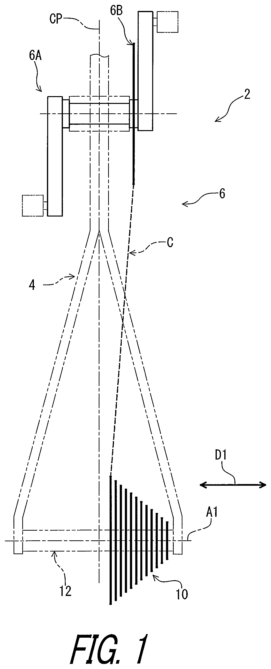
As seen in , a human-powered vehicle 2 includes a vehicle body 4 and a drive train 6 . The drive train 6 includes a rear sprocket assembly 10 and a rear hub assembly 12 . The rear hub assembly 12 is secured to the vehicle body 4 . The rear sprocket assembly 10 is configured to be mounted to the rear hub assembly 12 for the human-powered vehicle 2 . The rear sprocket assembly 10 has a rotational center axis A 1 to define an axial direction D 1 , a radial direction and a circumferential direction D 2 (see e.g., ). The rear sprocket assembly 10 is rotatably supported by the rear hub assembly 12 relative to the vehicle body 4 about the rotational center axis A 1 . The human-powered vehicle 2 has an axial center plane CP. The axial center plane CP is defined in a transverse center position of the vehicle body 4 of the human-powered vehicle 2 . The axial center plane CP is perpendicular to the rotational center axis A 1 .
The drive train 6 includes a crank assembly 6 A, a front sprocket 6 B, and a drive chain C. The crank assembly 6 A is rotatably mounted to the vehicle body 4 . The front sprocket 6 B is secured to crank assembly 6 A. The drive chain C is engaged with the front sprocket 6 B and the rear sprocket assembly 10 to transmit pedaling force from the front sprocket 6 B to the rear sprocket assembly 10 . The front sprocket 6 B includes a single sprocket wheel in the present embodiment. However, the front sprocket 6 B can include a plurality of sprocket wheels.
In the present application, the following directional terms “front,” “rear,” “forward,” “rearward,” “left,” “right,” “transverse,” “upward” and “downward” as well as any other similar directional terms refer to those directions which are determined on the basis of a user (e.g., a rider) who is in the user's standard position (e.g., on a saddle or a seat) in the human-powered vehicle 2 with facing a handlebar or steering. Accordingly, these terms, as utilized to describe the rear sprocket assembly 10 , the rear hub assembly 12 , or other components, should be interpreted relative to the human-powered vehicle 2 equipped with the rear sprocket assembly 10 , the rear hub assembly 12 , or other components as used in an upright riding position on a horizontal surface.
In the present application, a human-powered vehicle includes a various kind of bicycles such as a mountain bike, a road bike, a city bike, a cargo bike, a hand bike, and a recumbent bike. Furthermore, the human-powered vehicle includes an electric bike (E-bike). The electric bike includes an electrically assisted bicycle configured to assist propulsion of a vehicle with an electric motor. However, a total number of wheels of the human-powered vehicle is not limited to two. For example, the human-powered vehicle includes a vehicle having one wheel or three or more wheels. Especially, the human-powered vehicle does not include a vehicle that uses only an internal-combustion engine as motive power. Generally, a light road vehicle, which includes a vehicle that does not require a driver's license for a public road, is assumed as the human-powered vehicle.
As seen in , the rear sprocket assembly 10 includes a plurality of rear sprockets SP. The plurality of rear sprockets SP is configured to engage with the drive chain C. The plurality of rear sprockets SP includes rear sprockets SP 1 to SP 11 . The rear sprockets SP 1 to SP 11 can also be referred to as first to eleventh sprockets SP 1 to SP 11 , respectively. The total number of the plurality of rear sprockets SP is not limited to eleven.
The rear hub assembly 12 includes a hub axle 14 , a hub body 16 , and a sprocket support body 18 . The hub axle 14 is configured to be secured to the vehicle body 4 (see e.g., ) of the human-powered vehicle 2 . The hub body 16 is rotatably mounted on the hub axle 14 about the rotational center axis A 1 . The sprocket support body 18 is rotatably mounted on the hub axle 14 about the rotational center axis A 1 .
The rear sprocket assembly 10 is configured to be mounted to the sprocket support body 18 . The sprocket support body 18 includes a plurality of external spline teeth 18 A. The rear sprocket assembly 10 is configured to engage with the plurality of external spline teeth 18 A of the sprocket support body 18 .
As seen in , the rear hub assembly 12 includes a ratchet structure 20 . The ratchet structure 20 is configured to allow the sprocket support body 18 to rotate relative to the hub body 16 about the rotational center axis A 1 in only one rotational direction. The ratchet structure 20 is configured to restrict the sprocket support body 18 from rotating relative to the hub body 16 about the rotational center axis A 1 in the other rotational direction.
For example, upshifting occurs the drive chain C is shifted from a sprocket to a neighboring larger sprocket in an upshifting direction D 41 . Downshifting occurs the drive chain C is shifted from a sprocket to a neighboring smaller sprocket in a downshifting direction D 42 .
The rear sprocket SP 1 is configured to be mounted to the rear hub assembly 12 for the human-powered vehicle 2 . The second sprocket SP 2 is configured to be mounted to the rear hub assembly 12 for the human-powered vehicle 2 . The second sprocket SP 2 is adjacent to the rear sprocket SP 1 without another sprocket between the rear sprockets SP 1 and SP 2 . The second sprocket SP 2 can also be referred to as a neighboring sprocket SP 2 or a neighboring larger sprocket SP 2 .
The rear sprocket SP 1 has a first sprocket outer diameter DM 1 . The second sprocket SP 2 has a second sprocket outer diameter DM 2 larger than the first sprocket outer diameter DM 1 . The second sprocket SP 2 is adjacent to the rear sprocket SP 1 without another sprocket between the rear sprocket SP 1 and the second sprocket SP 2 in the axial direction D 1 with respect to the rotational center axis A 1 . The first sprocket outer diameter DM 1 is the smallest among outer diameters of the first to eleventh sprockets SP 1 to SP 11 in the present embodiment. Thus, the rear sprocket SP 1 is a smallest sprocket in the rear sprocket assembly 10 . The rear sprocket SP 1 can also be referred to as a top-gear sprocket SP 1 .
The third sprocket SP 3 has a third sprocket outer diameter DM 3 which is larger than the second sprocket outer diameter DM 2 . The third sprocket SP 3 is adjacent to the second sprocket SP 2 without another sprocket between the second sprocket SP 2 and the third sprocket SP 3 in the axial direction D 1 .
The rear sprocket assembly 10 includes a sprocket carrier 22 . The rear sprockets SP 5 to SP 11 are mounted on the sprocket carrier 22 . The rear sprockets SP 5 to SP 11 are secured to the sprocket carrier 22 with fasteners 24 such as rivets in the present embodiment. However, a total number of sprockets secured to the sprocket carrier 22 is not limited to the embodiment illustrated in . The sprocket carrier 22 is configured to be in contact with a positioning surface 18 C of the sprocket support body 18 . However, the structure of the sprocket carrier 22 is not limited to the structure illustrated in . The sprocket carrier 22 can be omitted from the rear sprocket assembly 10 if needed and/or desired. In such embodiments, all of the sprockets directly engage with the sprocket support body 18 .
As seen in , the rear sprocket SP 1 has the rotational center axis A 1 to define the axial direction D 1 , the radial direction and the circumferential direction D 2 . The rear sprocket SP 1 comprises a sprocket body S 11 and a plurality of sprocket teeth S 12 . The sprocket body S 11 has a sprocket opening S 13 . The sprocket opening S 13 has a minimum diameter DM 11 . The plurality of sprocket teeth S 12 extends radially outwardly from the sprocket body S 11 in the radial direction. The plurality of first sprocket teeth S 12 defines the first sprocket outer diameter DM 1 . The sprocket body S 11 can also be referred to as a first sprocket body S 11 . The sprocket tooth S 12 can also be referred to as a first sprocket tooth S 12 . The sprocket opening S 13 can also be referred to as a first sprocket opening S 13 . The minimum diameter DM 11 can also be referred to as a first minimum diameter DM 11 .
The plurality of sprocket teeth S 12 has a total sprocket-tooth number which is a total number of the sprocket teeth S 12 . The total sprocket-tooth number of the plurality of sprocket teeth S 12 is equal to or smaller than 10. In the present embodiment, the total sprocket-tooth number of the plurality of sprocket teeth S 12 is nine. However, the total sprocket-tooth number of the plurality of sprocket teeth S 12 is not limited to the above total number and the above range.
As seen in , the sprocket opening S 13 is configured to receive the hub axle 14 of the rear hub assembly 12 in a hub mounting state where the rear sprocket SP 1 is mounted to the rear hub assembly 12 . The minimum diameter DM 11 is smaller than an outermost diameter DM 6 of the sprocket support body 18 of the rear hub assembly 12 .
The rear sprocket SP 1 has an axially outwardly facing surface S 14 and an axially inwardly facing surface S 15 . The axially inwardly facing surface S 15 is provided on a reverse side of the axially outwardly facing surface S 14 in the axial direction D 1 . The axially inwardly facing surface S 15 is configured to face toward the axial center plane CP of the human-powered vehicle 2 in the axial direction D 1 in a vehicle mounting state where the rear sprocket SP 1 is mounted to the human-powered vehicle 2 . The axially outwardly facing surface S 14 can also be referred to as a first axially outwardly facing surface S 14 . The axially inwardly facing surface S 15 can also be referred to as a first axially inwardly facing surface S 15 .
As seen in , the plurality of sprocket teeth S 12 defines a plurality of tooth bottom center points S 12 A spaced apart from each other in the circumferential direction D 2 . Each of the plurality of sprocket teeth S 12 has a tooth outline OL extending from corresponding one of the plurality of tooth bottom center points S 12 A to a neighboring tooth bottom center point among the plurality of tooth bottom center points S 12 A in the circumferential direction D 2 . The plurality of tooth bottom center points S 12 A defines a root circle S 12 B. The tooth outline OL is indicated with a thick chain double-dashed line in .
The rear sprocket SP 1 comprises a plurality of spline teeth S 16 . The plurality of spline teeth S 16 is configured to transmit driving torque to the neighboring sprocket SP 2 (see e.g., ) adjacent to the rear sprocket SP 1 without another sprocket between the rear sprocket SP 1 and the neighboring sprocket SP 2 in the axial direction D 1 .
The plurality of spline teeth S 16 has a total spline-tooth number which is a total number of the spline teeth S 16 . The total spline-tooth number of the plurality of spline teeth S 16 ranges from 15 to 18. In the present embodiment, the total spline-tooth number of the plurality of spline teeth S 16 is 16. However, the total spline-tooth number of the plurality of spline teeth S 16 is not limited to the above total number and the above range.
The rear sprocket SP 1 further comprises an annular base S 17 from which the plurality of spline teeth S 16 extends radially outwardly in the radial direction. The annular base S 17 is disposed so as to surround the sprocket opening S 13 as viewed in the axial direction D 1 .
As seen in , at least two spline teeth of the plurality of spline teeth S 16 are disposed so as to overlap with one of the plurality of sprocket teeth S 12 as viewed in the axial direction D 1 . The plurality of spline teeth S 16 is disposed so as to be offset from the plurality of tooth bottom center points S 12 A in the circumferential direction D 2 .
The plurality of spline teeth S 16 includes at least one first spline tooth S 16 B and at least one second spline tooth S 16 C. The plurality of spline teeth S 16 includes at least two first spline teeth S 16 B and at least two second spline teeth S 16 C. The plurality of spline teeth S 16 includes at least two pairs of the first spline tooth S 16 B and the second spline tooth S 16 C. In the present embodiment, a total number of the at least two pairs of the first spline tooth S 16 B and the second spline tooth S 16 C is seven. However, the total number of the at least two pairs of the first spline tooth S 16 B and the second spline tooth S 16 C is not limited to seven.
In the pair of the first spline tooth S 16 B and the second spline tooth S 16 C, the second spline tooth S 16 C is adjacent to the first spline tooth S 16 B in the circumferential direction D 2 without another spline tooth between the first spline tooth S 16 B and the second spline tooth S 16 C in the circumferential direction D 2 . The first spline tooth S 16 B and the second spline tooth S 16 C are disposed so as to overlap with one of the plurality of sprocket teeth S 12 as viewed in the axial direction D 1 . Three or more spline teeth of the spline teeth S 16 can be disposed so as to overlap with one of the plurality of sprocket teeth S 12 as viewed in the axial direction D 1 if needed and/or desired.
The plurality of spline teeth S 16 includes at least one positioning spline tooth S 16 D and/or S 16 E. The at least one positioning spline tooth S 16 D and/or S 16 E is different from the other spline teeth of the plurality of spline teeth S 16 in at least one of size and shape. In the present embodiment, the plurality of spline teeth S 16 includes positioning spline teeth S 16 D and S 16 E. However, the plurality of spline teeth S 16 can include at least one positioning spline tooth if needed and/or desired.
The positioning spline tooth S 16 D is provided between one of the at least two pairs of the first spline tooth S 16 B and the second spline tooth S 16 C and another of the at least two pairs of the first spline tooth S 16 B and the second spline tooth S 16 C in the circumferential direction D 2 . The positioning spline tooth S 16 E is provided between one of the at least two pairs of the first spline tooth S 16 B and the second spline tooth S 16 C and another of the at least two pairs of the first spline tooth S 16 B and the second spline tooth S 16 C in the circumferential direction D 2 . The positioning spline tooth S 16 D is disposed so as to overlap with one of the plurality of sprocket teeth S 12 as viewed in the axial direction D 1 . The positioning spline tooth S 16 E is disposed so as to overlap with one of the plurality of sprocket teeth S 12 as viewed in the axial direction D 1 .
As seen in , the first spline tooth S 16 B has a circumferential spline width W 1 defined in the circumferential direction D 2 . The second spline tooth S 16 C has a circumferential spline width W 2 defined in the circumferential direction D 2 . The at least one positioning spline tooth S 16 D and/or S 16 E has a circumferential positioning-spline width W 3 and/or W 4 . The positioning spline tooth S 16 D has a circumferential positioning-spline width W 3 . The positioning spline tooth S 16 E has a circumferential positioning-spline width W 4 .
The circumferential positioning-spline width W 3 is larger than each of circumferential spline widths W 1 and W 2 of other spline teeth of the plurality of spline teeth S 16 . The circumferential positioning-spline width W 4 is larger than each of circumferential spline widths W 1 and W 2 of other spline teeth of the plurality of spline teeth S 16 . The at least one positioning spline tooth S 16 D and/or S 16 E has a circumferential positioning-spline width W 3 and/or W 4 which is larger than each of circumferential spline widths W 1 and W 2 of the other spline teeth of the plurality of spline teeth S 16 . In the present embodiment, the circumferential spline widths W 1 and W 2 are equal to each other. The circumferential positioning-spline width W 4 is different from the circumferential positioning-spline width W 3 . The circumferential positioning-spline width W 4 is larger than the circumferential positioning-spline width W 3 . However, each of the circumferential positioning-spline widths W 3 and W 4 can be equal to or smaller than at least one of the circumferential spline widths W 1 and W 2 if needed and/or desired. The circumferential positioning-spline width W 4 can be equal to or smaller than the circumferential positioning-spline width W 3 if needed and/or desired. The circumferential spline width W 2 can be different from the circumferential spline width W 1 if needed and/or desired.
The circumferential spline widths W 1 and W 2 range from 1.5 mm to 3.0 mm. The circumferential positioning-spline width W 3 ranges 1.5 mm to 3.0 mm. The circumferential positioning-spline width W 4 ranges 3.0 mm to 6.0 mm. In the present embodiment, the circumferential spline widths W 1 and W 2 are equal to 2.03 mm. The circumferential positioning-spline width W 3 is equal to 2.42 mm. The circumferential positioning-spline width W 4 is equal to 4.12 mm. However, the circumferential spline widths W 1 and W 2 are not limited to the above size and range. The circumferential positioning-spline width W 3 is not limited to the above size and range. The circumferential positioning-spline width W 4 is not limited to the above size and range.
A sum of the circumferential spline widths W 1 and W 2 and the circumferential positioning-spline widths W 3 and W 4 of the spline teeth S 16 B, S 16 C, S 16 D and S 16 E is larger than or equal to 11.0 mm in order to achieve sufficient strength of the plurality of spline teeth S 16 . The sum of the circumferential spline widths W 1 and W 2 and the circumferential positioning-spline widths W 3 and W 4 of the spline teeth S 16 B, S 16 C, S 16 D and S 16 E is smaller than or equal to 15.0 mm in order to increase the total number of the spline teeth 16 . Thus, the sum of the circumferential spline widths W 1 and W 2 and the circumferential positioning-spline widths W 3 and W 4 of the spline teeth S 16 B, S 16 C, S 16 D and S 16 E can range from 11.0 mm to 15.0 mm in order to achieve sufficient strength of the plurality of spline teeth S 16 and to increase the total number of the spline teeth 16 . In the present embodiment, the sum of the circumferential spline widths W 1 and W 2 and the circumferential positioning-spline widths W 3 and W 4 of the spline teeth S 16 B, S 16 C, S 16 D and S 16 E is 13.92 mm. However, the sum of the circumferential spline widths W 1 and W 2 and the circumferential positioning-spline widths W 3 and W 4 of the spline teeth S 16 B, S 16 C, S 16 D and S 16 E is not limited to the above size and range.
As seen in , at least one of the first spline teeth S 16 B has a circumferentially symmetrical shape with respect to the rotational center axis A 1 . Another of the first spline teeth S 16 B can have a circumferentially asymmetrical shape with respect to the rotational center axis A 1 . At least one of the second spline teeth S 16 C has a circumferentially symmetrical shape with respect to the rotational center axis A 1 . Another of the second spline teeth S 16 C can have a circumferentially symmetrical shape with respect to the rotational center axis A 1 . The positioning spline tooth S 16 D has a circumferentially asymmetrical shape with respect to the rotational center axis A 1 . The positioning spline tooth S 16 E has a circumferentially symmetrical shape with respect to the rotational center axis A 1 .
In the present embodiment, each of the first spline teeth S 16 B has a circumferentially symmetrical shape with respect to the rotational center axis A 1 . Six of the second spline teeth S 16 C has a circumferentially symmetrical shape with respect to the rotational center axis A 1 . One of the second spline teeth S 16 C has a circumferentially asymmetrical shape with respect to the rotational center axis A 1 . However, at least one of the first spline teeth S 16 B can have a circumferentially asymmetrical shape with respect to the rotational center axis A 1 if needed and/or desired. At least two of the second spline teeth S 16 C can have a circumferentially asymmetrical shape with respect to the rotational center axis A 1 if needed and/or desired. The positioning spline tooth S 16 D can have a circumferentially symmetrical shape with respect to the rotational center axis A 1 if needed and/or desired. The positioning spline tooth S 16 E can have a circumferentially asymmetrical shape with respect to the rotational center axis A 1 if needed and/or desired.
As seen in , the first spline tooth S 16 B having a circumferential symmetrical shape can also be referred to as a circumferentially symmetrical tooth S 16 B. The second spline tooth S 16 C having a circumferential symmetrical shape can also be referred to as a circumferentially symmetrical tooth S 16 C. The second spline tooth S 16 C having a circumferential asymmetrical shape can also be referred to as a circumferentially asymmetrical tooth S 16 C. The positioning spline tooth S 16 D having a circumferential asymmetrical shape can also be referred to as a circumferentially asymmetrical tooth S 16 D. The positioning spline tooth S 16 E having a circumferential symmetrical shape can also be referred to as a circumferentially symmetrical tooth S 16 E.
Namely, the plurality of spline teeth S 16 includes at least one circumferentially symmetrical tooth S 16 B, S 16 C, S 16 D, and/or S 16 E with respect to the rotational center axis A 1 . The plurality of spline teeth S 16 includes a plurality of circumferentially symmetrical teeth S 16 B, S 16 C, and S 16 E with respect to the rotational center axis A 1 . The plurality of spline teeth S 16 includes at least one circumferentially asymmetrical tooth S 16 B, S 16 C, S 16 D, and/or S 16 E with respect to the rotational center axis A 1 . The plurality of spline teeth S 16 includes a plurality of circumferentially asymmetrical teeth S 16 C and S 16 D with respect to the rotational center axis A 1 .
As seen in , each of the plurality of spline teeth S 16 has a spline crest S 16 A. The spline crest S 16 A includes a radially outer end of the spline tooth S 16 . Thus, the spline crest S 16 A can also be referred to as a radially outer end S 16 A. Each of the first spline tooth S 16 B, the second spline tooth S 16 C, the third spline tooth S 16 C, and the positioning spline tooth S 16 E includes the spline crest S 16 A.
A maximum spline distance DS 1 is defined from the rotational center axis A 1 to the spline crest S 16 A. A radial tooth-bottom distance DS 2 is defined from the rotational center axis A 1 to one of the plurality of tooth bottom center points S 12 A. The radial tooth-bottom distance DS 2 corresponds to a radius of the root circle S 12 B of the rear sprocket SP 1 .
The maximum spline distance DS 1 is larger than the radial tooth-bottom distance DS 2 . The spline crest S 16 A of each of the plurality of spline teeth S 16 is positioned radially inwardly from the tooth outline OL of each of the plurality of sprocket teeth S 12 in the radial direction. The spline crest S 16 A of each of the plurality of spline teeth S 16 is positioned radially outwardly from the root circle S 12 B of the rear sprocket SP 1 .
In the present embodiment, the maximum spline distance DS 1 of the first spline tooth S 16 B, the maximum spline distance DS 1 of the second spline tooth S 16 C, the maximum spline distance DS 1 of the positioning spline tooth S 16 D, and the maximum spline distance DS 1 of the positioning spline tooth S 16 E are equal to each other. However, at least one of the maximum spline distance DS 1 of the first spline tooth S 16 B, the maximum spline distance DS 1 of the second spline tooth S 16 C, the maximum spline distance DS 1 of the positioning spline tooth S 16 D, and the maximum spline distance DS 1 of the positioning spline tooth S 16 E can be different from another of the maximum spline distance DS 1 of the first spline tooth S 16 B, the maximum spline distance DS 1 of the second spline tooth S 16 C, the maximum spline distance DS 1 of the positioning spline tooth S 16 D, and the maximum spline distance DS 1 of the positioning spline tooth S 16 E if needed and/or desired.
As seen in , the first spline tooth S 16 B includes a driving spline surface S 16 B 1 and a non-driving spline surface S 16 B 2 . The driving spline surface S 16 B 1 faces in the driving rotational direction D 5 . The driving spline surface S 16 B 1 is configured to transmit the driving torque from the rear sprocket SP 1 to the neighboring sprocket SP 2 during pedaling. The non-driving spline surface S 16 B 2 is opposite to the driving spline surface S 16 B 1 in the circumferential direction D 2 . The driving spline surface S 16 B 1 can also be configured to directly transmit the driving torque from the rear sprocket SP 1 to the sprocket support body 18 of the rear hub assembly 12 during pedaling.
The second spline tooth S 16 C includes a driving spline surface S 16 C 1 and a non-driving spline surface S 16 C 2 . The driving spline surface S 16 C 1 faces in the driving rotational direction D 5 . The driving spline surface S 16 C 1 is configured to transmit the driving torque from the rear sprocket SP 1 to the neighboring sprocket SP 2 during pedaling. The non-driving spline surface S 16 C 2 is opposite to the driving spline surface S 16 C 1 in the circumferential direction D 2 . The driving spline surface S 16 C 1 can also be configured to directly transmit the driving torque from the rear sprocket SP 1 to the sprocket support body 18 of the rear hub assembly 12 during pedaling.
The positioning spline tooth S 16 E includes a driving spline surface S 16 E 1 and a non-driving spline surface S 16 E 2 . The driving spline surface S 16 E 1 faces in the driving rotational direction D 5 . The driving spline surface S 16 E 1 is configured to transmit the driving torque from the rear sprocket SP 1 to the neighboring sprocket SP 2 during pedaling. The non-driving spline surface S 16 E 2 is opposite to the driving spline surface S 16 E 1 in the circumferential direction D 2 . The driving spline surface S 16 E 1 can also be configured to directly transmit the driving torque from the rear sprocket SP 1 to the sprocket support body 18 of the rear hub assembly 12 during pedaling.
As seen in , the positioning spline tooth S 16 D includes a driving spline surface S 16 D 1 and a non-driving spline surface S 16 D 2 . The driving spline surface S 16 D 1 faces in the driving rotational direction D 5 . The driving spline surface S 16 D 1 is configured to transmit the driving torque from the rear sprocket SP 1 to the neighboring sprocket SP 2 during pedaling. The non-driving spline surface S 16 D 2 is opposite to the driving spline surface S 16 D 1 in the circumferential direction D 2 . The driving spline surface S 16 D 1 can also be configured to directly transmit the driving torque from the rear sprocket SP 1 to the sprocket support body 18 of the rear hub assembly 12 during pedaling.
As seen in , the driving spline surface S 16 B 1 of the first spline tooth S 16 B has an axial length L 1 and a radial length H 1 . The axial length L 1 is defined in the axial direction D 1 . The radial length H 1 is defined in the radial direction of the rear sprocket SP 1 . The axial length L 1 ranges from 0.7 mm to 1.1 mm. The radial length H 1 ranges from 0.27 mm to 0.4 mm. In the present embodiment, the axial length L 1 is equal to 0.87 mm. The radial length H 1 is equal to 0.34 mm. However, the axial length L 1 is not limited to the above size and range. The radial length H 1 is not limited to the above size and range.
The driving spline surface S 16 C 1 of the second spline tooth S 16 C has an axial length L 2 and a radial length H 2 . The axial length L 2 is defined in the axial direction D 1 . The radial length H 2 is defined in the radial direction of the rear sprocket SP 1 . The axial length L 2 ranges from 0.7 mm to 1.1 mm. The radial length H 2 ranges from 0.27 mm to 0.4 mm. In the present embodiment, the axial length L 2 is equal to 0.87 mm. The radial length H 2 is equal to 0.34 mm. However, the axial length L 2 is not limited to the above size and range. The radial length H 2 is not limited to the above size and range.
The driving spline surface S 16 E 1 of the positioning spline tooth S 16 E has an axial length L 4 and a radial length H 4 . The axial length L 4 is defined in the axial direction D 1 . The radial length H 4 is defined in the radial direction of the rear sprocket SP 1 . The axial length L 4 ranges from 0.7 mm to 1.1 mm. The radial length H 4 ranges from 0.27 mm to 0.4 mm. In the present embodiment, the axial length L 4 is equal to 0.87 mm. The radial length H 4 is equal to 0.34 mm. However, the axial length L 4 is not limited to the above size and range. The radial length H 4 is not limited to the above size and range.
As seen in , the driving spline surface S 16 D 1 of the positioning spline tooth S 16 D has an axial length L 3 and a radial length H 3 . The axial length L 3 is defined in the axial direction D 1 . The radial length H 3 is defined in the radial direction of the rear sprocket SP 1 . The axial length L 3 ranges from 0.7 mm to 1.1 mm. The radial length H 3 ranges from 0.27 mm to 0.4 mm. In the present embodiment, the axial length L 3 is equal to 0.87 mm. The radial length H 3 is equal to 0.34 mm. However, the axial length L 3 is not limited to the above size and range. The radial length H 3 is not limited to the above size and range.
A sum of the axial lengths L 1 , L 2 , L 3 and L 4 of the driving spline surfaces S 16 B 1 , S 16 C 1 , S 16 D 1 and S 16 E 1 in the plurality of spline teeth S 16 is larger than 11.0 mm in order to achieve sufficient strength of the plurality of spline teeth S 16 . The sum of the axial lengths L 1 , L 2 , L 3 and L 4 of the driving spline surfaces S 16 B 1 , S 16 C 1 , S 16 D 1 and S 16 E 1 in the plurality of spline teeth S 16 is preferably larger than 13.0 mm in order to achieve sufficient strength of the plurality of spline teeth S 16 . The sum of the axial lengths L 1 , L 2 , L 3 and L 4 of the driving spline surfaces S 16 B 1 , S 16 C 1 , S 16 D 1 and S 16 E 1 in the plurality of spline teeth S 16 can range from 11.0 mm to 16.0 mm in order to achieve sufficient strength of the plurality of spline teeth S 16 and to save axial space of the plurality of spline teeth S 16 . In the present embodiment, the sum of the axial lengths L 1 , L 2 , L 3 and L 4 of the driving spline surfaces S 16 B 1 , S 16 C 1 , S 16 D 1 and S 16 E 1 in the plurality of spline teeth S 16 is 13.92 mm. However, the sum of the axial lengths L 1 , L 2 , L 3 and L 4 of the driving spline surfaces S 16 B 1 , S 16 C 1 , S 16 D 1 and S 16 E 1 in the plurality of spline teeth S 16 is not limited to the above size and range.
A sum of the radial lengths H 1 , H 2 , H 3 and H 4 of the driving spline surfaces S 16 B 1 , S 16 C 1 , S 16 D 1 and S 16 E 1 in the plurality of spline teeth S 16 is larger than 4.0 mm in order to achieve sufficient strength of the plurality of spline teeth S 16 . The sum of the radial lengths H 1 , H 2 , H 3 and H 4 of the driving spline surfaces S 16 B 1 , S 16 C 1 , S 16 D 1 and S 16 E 1 in the plurality of spline teeth S 16 is preferably larger than 5.0 mm in order to achieve sufficient strength of the plurality of spline teeth S 16 . The sum of the radial lengths H 1 , H 2 , H 3 and H 4 of the driving spline surfaces S 16 B 1 , S 16 C 1 , S 16 D 1 and S 16 E 1 in the plurality of spline teeth S 16 can range from 4.0 mm to 7.0 mm in order to achieve sufficient strength of the plurality of spline teeth S 16 and to save radial space of the plurality of spline teeth S 16 . In the present embodiment, the sum of the radial lengths H 1 , H 2 , H 3 and H 4 of the driving spline surfaces S 16 B 1 , S 16 C 1 , S 16 D 1 and S 16 E 1 in the plurality of spline teeth S 16 is 5.44 mm. However, the sum of the radial lengths H 1 , H 2 , H 3 and H 4 of the driving spline surfaces S 16 B 1 , S 16 C 1 , S 16 D 1 and S 16 E 1 in the plurality of spline teeth S 16 is not limited to the above size and range.
As seen in to 14 , the annular base S 17 extends axially inwardly from the axially inwardly facing surface S 15 of the sprocket body S 11 in the axial direction D 1 . The plurality of spline teeth S 16 is spaced apart from the plurality of sprocket teeth S 12 in the axial direction D 1 . However, at least one spline tooth of the plurality of spline teeth S 16 can be directly coupled to corresponding one of the plurality of sprocket teeth S 12 if needed and/or desired.
As seen in , the first spline tooth S 16 B extends radially outwardly from the annular base S 17 . The first spline tooth S 16 B is spaced apart from the plurality of sprocket teeth S 12 in the axial direction D 1 . However, the first spline teeth S 16 B can be directly coupled to corresponding one of the plurality of sprocket teeth S 12 if needed and/or desired.
As seen in , the second spline tooth S 16 C extends radially outwardly from the annular base S 17 . The second spline tooth S 16 C is spaced apart from the plurality of sprocket teeth S 12 in the axial direction D 1 . However, the second spline teeth S 16 C can be directly coupled to corresponding one of the plurality of sprocket teeth S 12 if needed and/or desired.
As seen in , the positioning spline tooth S 16 D extends radially outwardly from the annular base S 17 . The positioning spline tooth S 16 D is spaced apart from the plurality of sprocket teeth S 12 in the axial direction D 1 . However, the third spline teeth S 16 D can be directly coupled to corresponding one of the plurality of sprocket teeth S 12 if needed and/or desired.
As seen in , the positioning spline tooth S 16 E extends radially outwardly from the annular base S 17 . The positioning spline tooth S 16 E is spaced apart from the plurality of sprocket teeth S 12 in the axial direction D 1 . However, the positioning spline teeth S 16 E can be directly coupled to corresponding one of the plurality of sprocket teeth S 12 if needed and/or desired.
As seen in , the neighboring sprocket SP 2 includes a second sprocket body S 21 and a plurality of second sprocket teeth S 22 . The second sprocket body S 21 has a second sprocket opening S 23 . The second sprocket opening S 23 has a second minimum diameter DM 21 . The plurality of second sprocket teeth S 22 extends radially outwardly from the second sprocket body S 21 in the radial direction with respect to the rotational center axis A 1 . The plurality of second sprocket teeth S 22 defines the second sprocket outer diameter DM 2 . In the present embodiment, a total number of the second sprocket teeth S 22 is eleven. However, the total number of the second sprocket teeth S 22 is not limited to eleven.
As seen in , the second sprocket opening S 23 is configured to receive the hub axle 14 of the rear hub assembly 12 in the hub mounting state where the rear sprocket SP 1 and the neighboring sprocket SP 2 are mounted to the rear hub assembly 12 . The second minimum diameter DM 21 is smaller than the outermost diameter DM 6 of the sprocket support body 18 of the rear hub assembly 12 .
The rear sprocket SP 1 further has a second axially outwardly facing surface S 24 and a second axially inwardly facing surface S 25 . The second axially inwardly facing surface S 25 is provided on a reverse side of the second axially outwardly facing surface S 24 in the axial direction D 1 . The second axially inwardly facing surface S 25 is configured to face toward the axial center plane CP of the human-powered vehicle 2 in the axial direction D 1 in the vehicle mounting state where the rear sprocket SP 1 and the neighboring sprocket SP 2 are mounted to the human-powered vehicle 2 .
As seen in , the neighboring sprocket SP 2 includes a plurality of spline recesses S 26 . The plurality of spline recesses S 26 is provided on the second axially outwardly facing surface S 24 . The plurality of spline recesses S 26 includes at least one first spline recess S 26 B and at least one second spline recess S 26 C. The plurality of spline recesses S 26 includes at least two first spline recesses S 26 B and at least two second spline recesses S 26 C. The plurality of spline recesses S 26 includes at least two pairs of the first spline recess S 26 B and the second spline recess S 26 C. In the present embodiment, a total number of the at least two pairs of the first spline recess S 26 B and the second spline recess S 26 C is seven. The plurality of spline recesses S 26 includes positioning spline recesses S 26 D and S 26 E. However, the total number of the at least two pairs of the first spline recess S 26 B and the second spline recess S 26 C is not limited to seven.
In the pair of the first spline recess S 26 B and the second spline recess S 26 C, the second spline recess S 26 C is adjacent to the first spline recess S 26 B in the circumferential direction D 2 without another spline recess between the first spline recess S 26 B and the second spline recess S 26 C in the circumferential direction D 2 .
The plurality of spline recesses S 26 includes at least one positioning spline recess S 26 D and/or S 26 E. The at least one positioning spline recess S 26 D and/or S 26 E is different from the other spline recesses of the plurality of spline recesses S 26 in at least one of size and shape. In the present embodiment, the plurality of spline recesses S 26 includes positioning spline recesses S 26 D and S 26 E. However, the plurality of spline recesses S 26 can include at least one positioning spline recess if needed and/or desired.
The positioning spline recess S 26 D is provided between one of the at least two pairs of the first spline recess S 26 B and the second spline recess S 26 C and another of the at least two pairs of the first spline recess S 26 B and the second spline recess S 26 C in the circumferential direction D 2 . The positioning spline recess S 26 E is provided between one of the at least two pairs of the first spline recess S 26 B and the second spline recess S 26 C and another of the at least two pairs of the first spline recess S 26 B and the second spline recess S 26 C in the circumferential direction D 2 .
As seen in , the plurality of spline tooth S 16 is engaged with the plurality of spline recesses S 26 to transmit the driving torque between the rear sprocket SP 1 and the neighboring sprocket SP 2 . The spline tooth S 16 is configured to be at least partly provided in the spline recess S 26 in the hub mounting state where the rear sprocket SP 1 and the neighboring sprocket SP 2 are mounted to the rear hub assembly 12 . The first spline tooth S 16 B is configured to be at least partly provided in the first spline recess S 26 B in the hub mounting state where the rear sprocket SP 1 and the neighboring sprocket SP 2 are mounted to the rear hub assembly 12 . The second spline tooth S 16 C is configured to be at least partly provided in the second spline recess S 26 C in the hub mounting state where the rear sprocket SP 1 and the neighboring sprocket SP 2 are mounted to the rear hub assembly 12 . The positioning spline tooth S 16 D is configured to be at least partly provided in the positioning spline recess S 26 D in the hub mounting state where the rear sprocket SP 1 and the neighboring sprocket SP 2 are mounted to the rear hub assembly 12 . The positioning spline tooth S 16 E is configured to be at least partly provided in the positioning spline recess S 26 E in the hub mounting state where the rear sprocket SP 1 and the neighboring sprocket SP 2 are mounted to the rear hub assembly 12 .
As seen in , the rear sprocket assembly 10 comprises a lock device 26 . The lock device 26 is configured to fix the rear sprocket assembly 10 to the sprocket support body 18 of the rear hub assembly 12 in the hub mounting state. The lock device 26 is configured to mount the rear sprocket SP 1 and the neighboring sprocket SP 2 to the rear hub assembly 12 . The lock device 26 is configured to be attached to the sprocket support body 18 to hold the sprocket carrier 22 and the first to fourth sprockets SP 1 to SP 4 between the lock device 26 and the positioning surface 18 C (see e.g., ) of the sprocket support body 18 in the axial direction D 1 .
The lock device 26 includes an axially inward end 26 A and an axially outward end 26 B. The lock device 26 extends between the axially inward end 26 A and the axially outward end 26 B in the axial direction D 1 . The axially outward end 26 B is opposite to the axially inward end 26 A in the axial direction D 1 . The lock device 26 includes a first lock member 28 and a second lock member 30 . The first lock member 28 includes the axially inward end 26 A. The second lock member 30 includes the axially outward end 26 B.
The first lock member 28 is configured to detachably engage with the sprocket support body 18 of the rear hub assembly 12 in the hub mounting state. The second lock member 30 is configured to detachably engage with the first lock member 28 so as to abut against the rear sprocket SP 1 in the axial direction D 1 in the hub mounting state.
The first lock member 28 is configured to detachably and reattachably engage with the axial end 18 B of the sprocket support body 18 in the hub mounting state. The first lock member 28 is configured to be at least partly provided in the second sprocket opening S 23 in the hub mounting state. The second lock member 30 is configured to be at least partly provided in the first sprocket opening S 13 and the second sprocket opening S 23 in the hub mounting state.
The term “detachably” or “detachably and reattachably” as used herein, encompasses a configuration in which an element is repeatedly detachable from and attachable to another element without substantial damage.
As seen in , the first lock member 28 includes a first axial end 28 A and a second axial end 28 B. The second axial end 28 B is opposite to the first axial end 28 A in the axial direction D 1 . The first axial end 28 A is configured to be detachably attached to the sprocket support body 18 of the rear hub assembly 12 in the hub mounting state. The first axial end 28 A is configured to be detachably and reattachably attached to the sprocket support body 18 of the rear hub assembly 12 in the hub mounting state.
The first axial end 28 A has first threads 28 D. The second axial end 28 B has second threads 28 E. The axially inward end 26 A has the first threads 28 D. In the present embodiment, the first threads 28 D include external threads. The second threads 28 E include internal threads. However, the first threads 28 D can include internal threads if needed and/or desired. The second threads 28 E can include external threads if needed and/or desired.
The first threads 28 D are configured to threadedly engage with threads 18 D provided to the sprocket support body 18 of the rear hub assembly 12 in the hub mounting state where the rear sprocket assembly 10 is mounted to the rear hub assembly 12 . In the present embodiment, the threads 18 D includes internal threads. However, the threads 18 D can include external threads if needed and/or desired.
The first lock member 28 includes a first surface 28 C. The first surface 28 C radially outwardly faces in the radial direction with respect to the rotational center axis A 1 . The first surface 28 C is adjacent to the first threads 28 D. The first threads 28 D of the first lock member 28 extend radially outwardly from the first surface 28 C in the radial direction. The first surface 28 C extends from the first threads 28 D in the axial direction D 1 . The second threads 28 E are provided radially inwardly of the first surface 28 C.
As seen in , the second lock member 30 includes a third axial end 30 A and a fourth axial end 30 B. The fourth axial end 30 B is opposite to the third axial end 30 A in the axial direction D 1 . The third axial end 30 A is configured to be attached to the second axial end 28 B of the first lock member 28 in an assembled state where the rear sprocket SP 1 and the lock device 26 are assembled as one unit. The third axial end 30 A of the second lock member 30 is configured to be detachably attached to the second axial end 28 B of the first lock member 28 in the assembled state where the rear sprocket SP 1 and the lock device 26 are assembled as one unit.
The third axial end 30 A has third threads 30 D. The third threads 30 D are configured to threadedly engage with the second threads 28 E of the first lock member 28 in the assembled state where the rear sprocket SP 1 and the lock device 26 are assembled as one unit. The fourth axial end 30 B has at least one radial projection 30 F. Namely, the axially outward end 26 B has the at least one radial projection 30 F. In the present embodiment, the third threads 30 D includes external threads. However, the third threads 30 D can include internal threads if needed and/or desired. Furthermore, the third axial end 30 A of the second lock member 30 may be attached to the second axial end 28 B of the first lock member 28 by spline engagement in a press-fitted manner.
The second lock member 30 includes a second surface 30 C. The second surface 30 C radially outwardly faces in the radial direction. The second surface 30 C is adjacent to the third threads 30 D. The second surface 30 C is adjacent to the at least one radial projection 30 F in the axial direction D 1 . The second surface 30 C is disposed between the third threads 30 D and the at least one radial projection 30 F. The second surface 30 C extends from the third threads 30 D in the axial direction D 1 . The second surface 30 C extends from the at least one radial projection 30 F in the axial direction D 1 in the axial direction D 1 . The at least one radial projection 30 F of the second lock member 30 extends radially outwardly from the second surface 30 C in the radial direction. The first surface 28 C is disposed radially outwardly from the second surface 30 C with respect to the rotational center axis A 1 in the assembled state where the rear sprocket SP 1 and the lock device 26 are assembled as one unit.
The at least one radial projection 30 F is configured to abut against the rear sprocket SP 1 in the axial direction D 1 in the hub mounting state where the rear sprocket assembly 10 is mounted to the rear hub assembly 12 . The at least one radial projection 30 F has a flange shape. The at least one radial projection 30 F has an annular shape. However, the at least one radial projection 30 F may include a plurality of radial projections if needed and/or desired. The at least one radial projection 30 F may have shapes other than the flange shape and the annular shape if needed and/or desired. An intermediate member such as a washer can be provided between the at least one radial projection 30 F and the rear sprocket SP 1 in the axial direction D 1 if needed and/or desired.
As seen in , the first lock member 28 has an axial contact surface 28 F disposed radially inwardly from the first surface 28 C. The axial contact surface 28 F is configured to contact the third axial end 30 A of the second lock member 30 in the assembled state where the rear sprocket SP 1 and the lock device 26 are assembled as one unit. The axial contact surface 28 F is configured to contact the third axial end 30 A of the second lock member 30 in the assembled state where the rear sprocket SP 1 and the lock device 26 are assembled as one unit. The axial contact surface 28 F is configured to contact the third axial end 30 A of the second lock member 30 in the assembled state where the first lock member 28 , the second lock member 30 , and the at least two sprockets of the plurality of rear sprockets SP are assembled as one unit. The axial contact surface 28 F is configured to contact the third axial end 30 A of the second lock member 30 in the assembled state where the first lock member 28 , the second lock member 30 , and the rear sprocket SP 1 are assembled as one unit.
As seen in , the lock device 26 is configured to arrange the rear sprocket SP 1 between the first threads 28 D of the first lock member 28 and the at least one radial projection 30 F of the second lock member 30 in the axial direction D 1 in the assembled state where the rear sprocket SP 1 and the lock device 26 are assembled as one unit. The rear sprocket SP 1 is configured to be disposed between the at least one radial projection 30 F of the second lock member 30 and the sprocket support body 18 of the rear hub assembly 12 in the axial direction D 1 in the hub mounting state. The first lock member 28 and the second lock member 30 are configured to arrange the rear sprocket SP 1 between the first threads 28 D of the first lock member 28 and the at least one radial projection 30 F of the second lock member 30 in the axial direction D 1 in the assembled state where the first lock member 28 , the second lock member 30 , and the rear sprocket SP 1 are assembled as one unit.
The at least one radial projection 30 F has a radially maximum projection diameter DM 4 . The first threads 28 D have a first maximum thread diameter DM 5 . The first maximum thread diameter DM 5 is an external major diameter of the first threads 28 D. The first minimum diameter DM 11 of the first sprocket opening S 13 is smaller than each of the first maximum thread diameter DM 5 of the first threads 28 D and the radially maximum projection diameter DM 4 of the at least one radial projection 30 F. Thus, the rear sprocket SP 1 is provided between the first threads 28 D and the at least one radial projection 30 F in the axial direction D 1 without dropping off from the lock device 26 .
The second minimum diameter DM 21 of the second sprocket opening S 23 is smaller than the radially maximum projection diameter DM 4 of the at least one radial projection 30 F. The second minimum diameter DM 21 of the second sprocket opening S 23 is larger than the first maximum thread diameter DM 5 of the first threads 28 D. Thus, the first threads 28 D of the lock device 26 is configured to be inserted into the second sprocket opening S 23 of the neighboring sprocket SP 2 in the assembled state where the rear sprocket SP 1 and the lock device 26 are assembled as one unit. However, the second minimum diameter DM 21 of the second sprocket opening S 23 can be smaller than or equal to the first maximum thread diameter DM 5 of the first threads 28 D if needed and/or desired. In such embodiments, the rear sprocket SP 1 and the neighboring sprocket SP 2 are provided between the first threads 28 D and the at least one radial projection 30 F in the axial direction D 1 without dropping off from the lock device 26 .
As seen in , the first axial end 28 A of the first lock member 28 includes a first tool engagement profile 28 G. In the present embodiment, the first tool engagement profile 28 G includes a plurality of first tool engagement recesses 28 G 1 . The first tool engagement recesses 28 G 1 are circumferentially arranged at constant intervals. However, the structure of the first tool engagement profile 28 G is not limited to the first tool engagement recesses 28 G 1 .
The fourth axial end 30 B of the second lock member 30 includes a second tool engagement profile 30 G. In the present embodiment, the at least one radial projection 30 F includes the second tool engagement profile 30 G. The second tool engagement profile 30 G includes a plurality of second tool engagement recesses 30 G 1 . The second tool engagement recesses 30 G 1 are circumferential arranged at constant intervals. However, the structure of the second tool engagement profile 30 G is not limited to the second tool engagement recesses 30 G 1 .
The first tool engagement profile 28 G is configured to be engaged with a first tool. The second tool engagement profile 30 G is configured to be engaged with a second tool. The first lock member 28 and the second lock member 30 are rotated relative to each other using the first tool and the second tool in a state where the first tool is engaged with the first tool engagement profile 28 G and the second tool is engaged with the second tool engagement profile 30 G. Thus, the third threads 30 D of the second lock member 30 is screwed into the second threads 28 E of the first lock member 28 .
As seen in , the neighboring sprocket SP 2 includes a axially inwardly torque transmitting profile S 27 provided to the second axially inwardly facing surface S 25 . The axially inwardly torque transmitting profile S 27 is configured to engage with at least one of a torque transmitting profile provided to the third sprocket SP 3 and the plurality of external spline teeth 18 A of the sprocket support body 18 in a torque-transmitting manner.
In the present embodiment, the axially inwardly torque transmitting profile S 27 is configured to engage with the plurality of external spline teeth 18 A of the sprocket support body 18 in a torque-transmitting manner. However, the axially inwardly torque transmitting profile S 27 can be configured to engage with a torque transmitting profile provided to the sprocket support body 18 in a torque-transmitting manner if needed and/or desired.
As seen in , the axially inwardly torque transmitting profile S 27 includes a plurality of torque transmitting recesses S 27 A. The plurality of torque transmitting recesses S 27 A includes a plurality of torque transmitting recesses S 27 A 1 and a positioning recess S 27 A 2 . The third positioning recess S 27 A 2 that has a different shape and/or size from the other of the plurality of torque transmitting recesses S 27 A 1 . In the present embodiment, the third positioning recess S 27 A 2 has a circumferential width which is larger than a circumferential width of the torque transmitting recess S 27 A 1 .
As seen in , the plurality of external spline teeth 18 A includes a plurality of external spline teeth 18 A 1 and an external positioning tooth 18 A 2 . The plurality of external spline teeth 18 A includes at least two external spline teeth 18 A 1 and an external positioning tooth 18 A 2 . The external positioning tooth 18 A 2 that has a different shape and/or size from the other of the at least two external spline teeth 18 A 1 . In the present embodiment, the external positioning tooth 18 A 2 has a circumferential width which is larger than a circumferential width of the external spline tooth 18 A 1 .
As seen in , the external spline teeth 18 A of the sprocket support body 18 are configured to respectively engage with the torque transmitting recesses S 27 A of the neighboring sprocket SP 2 in a torque transmitting manner. In the present embodiment, the external spline teeth 18 A 1 of the sprocket support body 18 are configured to respectively engage with the torque transmitting recesses S 27 A 1 of the neighboring sprocket SP 2 . The external positioning tooth 18 A 2 of the sprocket support body 18 is configured to engage with the third positioning recess S 27 A 2 of the neighboring sprocket SP 2 . The external positioning tooth 18 A 2 is configured not to engage with the torque transmitting recess S 27 A 1 since the circumferential width of the external positioning tooth 18 A 2 is larger than the circumferential width of the torque transmitting recess S 27 A 1 . Thus, the external positioning tooth 18 A 2 and the third positioning recess S 27 A 2 define a single circumferential position of the sprocket support body 18 relative to the neighboring sprocket SP 2 .
The assembly procedure in which the rear sprocket assembly 10 is assembled to the rear hub assembly 12 will be described below referring to , 5 , and 19 to 21 .
As seen in , the third to eleventh sprockets SP 3 to SP 11 and the sprocket carrier 22 are mounted to the sprocket support body 18 before the neighboring sprocket SP 2 and the lock device assembly 50 are mounted to the sprocket support body 18 . The neighboring sprocket SP 2 is mounted to the sprocket support body 18 after the third to eleventh sprockets SP 3 to SP 11 and the sprocket carrier 22 are mounted to the sprocket support body 18 .
As seen in , for example, the neighboring sprocket SP 2 is rotated by the user relative to the sprocket support body 18 about the rotational center axis A 1 so that the neighboring sprocket SP 2 is positioned in a predetermined circumferential position relative to the sprocket support body 18 .
In a state where the neighboring sprocket SP 2 is positioned in the predetermined circumferential position, the axially inwardly torque transmitting profile S 27 of the neighboring sprocket SP 2 is brought into engagement with the plurality of external spline teeth 18 A of the sprocket support body 18 . Specifically, in the state where the neighboring sprocket SP 2 is positioned in the predetermined circumferential position, the torque transmitting recess S 27 A 1 (see e.g., ) of the axially inwardly torque transmitting profile S 27 is brought into engagement with the external spline tooth 18 A 1 (see e.g., ) of the sprocket support body 18 . In the state where the neighboring sprocket SP 2 is positioned in the predetermined circumferential position, the third positioning recess S 27 A 2 (see e.g., ) of the axially inwardly torque transmitting profile S 27 is brought into engagement with the external positioning tooth 18 A 2 (see e.g., ) of the sprocket support body 18 . Thus, the neighboring sprocket SP 2 is engaged with the sprocket support body 18 in the predetermined circumferential position about the rotational center axis A 1 .
As seen in , the lock device assembly 50 is mounted to the sprocket support body 18 after the neighboring sprocket SP 2 is mounted to the sprocket support body 18 . For example, the rear sprocket SP 1 is rotated by the user relative to the sprocket support body 18 and the neighboring sprocket SP 2 about the rotational center axis A 1 so that the rear sprocket SP 1 is positioned in a predetermined circumferential position relative to the sprocket support body 18 and the neighboring sprocket SP 2 . In the state where the rear sprocket SP 1 is positioned in the predetermined circumferential position, the plurality of spline teeth S 16 of the rear sprocket SP 1 is brought into engagement with the plurality of spline recesses S 26 of the neighboring sprocket SP 2 . In the state where the rear sprocket SP 1 is positioned in the predetermined circumferential position, the first spline teeth S 16 B, the second spline teeth S 16 C, the positioning spline tooth S 16 D, and the positioning spline tooth S 16 E are brought into engagement with the first spline recesses S 26 B, the second spline recesses S 26 C, the positioning spline recess S 26 D, and the positioning spline recess S 26 E.
As seen in , the lock device 26 is rotated by the user relative to the sprocket support body 18 about the rotational center axis A 1 after the plurality of spline teeth S 16 of the rear sprocket SP 1 is brought into engagement with the plurality of spline recesses S 26 of the neighboring sprocket SP 2 . The first threads 28 D of the first lock member 28 are screwed into the threads 18 D of the sprocket support body 18 while the lock device 26 is rotated by the user relative to the sprocket support body 18 about the rotational center axis A 1 .
The first threads 28 D and the threads 18 D convert the rotation of the lock device 26 into an axial movement of the lock device 26 relative to the sprocket support body 18 in the axial direction D 1 . Thus, the lock device 26 is moved relative to the sprocket support body 18 in a first axial direction D 11 when the first threads 28 D are screwed into the threads 18 D of the sprocket support body 18 . The at least one radial projection 30 F is moved relative to the rear sprocket SP 1 from the first end position P 21 toward the second end position P 22 when the first threads 28 D are screwed into the threads 18 D of the sprocket support body 18 .
As seen in , the rear sprocket SP 1 and the neighboring sprocket SP 2 are held between the at least one radial projection 30 F of the second lock member 30 and the sprocket support body 18 in the axial direction D 1 . Thus, the rear sprocket assembly 10 is assembled to the rear hub assembly 12 .
As seen in , the plurality of sprocket teeth S 12 includes a first upshifting facilitation tooth S 12 C, a second upshifting facilitation tooth S 12 D, a third upshifting facilitation tooth S 12 E and an upshifting initiation tooth S 12 F. The first upshifting facilitation tooth S 12 C, the second upshifting facilitation tooth S 12 D and the third upshifting facilitation tooth S 12 E are configured to facilitate an upshifting operation where the drive chain C is shifted from the neighboring larger sprocket SP 2 toward the rear sprocket SP 1 . The upshifting initiation tooth S 12 F is configured to firstly engage with the drive chain C during the upshifting operation. The upshifting initiation tooth S 12 F is configured to firstly be inserted into a space provided between an opposed pair of link plates of the drive chain C during the upshifting operation. Specifically, the upshifting initiation tooth S 12 F is configured to firstly be inserted into a space provided between an opposed pair of outer link plates of the drive chain C during the upshifting operation. The drive chain C is shifted from the neighboring larger sprocket SP 2 toward the rear sprocket SP 1 by a gear changing device such as a derailleur.
The second upshifting facilitation tooth S 12 D is adjacent to the first upshifting facilitation tooth S 12 C at an upstream side of the first upshifting facilitation tooth S 12 C with respect to a driving rotational direction D 5 of the rear sprocket SP 1 without another tooth between the first upshifting facilitation tooth S 12 C and the second upshifting facilitation tooth S 12 D in the circumferential direction D 2 . The second upshifting facilitation tooth S 12 D is provided on the upstream side of the first upshifting facilitation tooth S 12 C in the driving rotational direction D 5 . The rear sprocket SP 1 is rotated about the rotational center axis A 1 in the driving rotational direction D 5 during pedaling.
The third upshifting facilitation tooth S 12 E is adjacent to the second upshifting facilitation tooth S 12 D at an upstream side of the second upshifting facilitation tooth S 12 D with respect to the driving rotational direction D 5 of the rear sprocket SP 1 without another tooth between the second upshifting facilitation tooth S 12 D and the third upshifting facilitation tooth S 12 E in the circumferential direction D 2 . The third upshifting facilitation tooth S 12 E is provided on the upstream side of the second upshifting facilitation tooth S 12 D in the driving rotational direction D 5 .
The upshifting initiation tooth S 12 F is adjacent to the third upshifting facilitation tooth S 12 E at an upstream side of the third upshifting facilitation tooth S 12 E with respect to the driving rotational direction D 5 of the rear sprocket SP 1 without another tooth between the third upshifting facilitation tooth S 12 E and the upshifting initiation tooth S 12 F in the circumferential direction D 2 . The upshifting initiation tooth S 12 F is provided on the upstream side of the third upshifting facilitation tooth S 12 E in the driving rotational direction D 5 .
As seen in , the first upshifting facilitation tooth S 12 C has a first recess S 12 C 1 . The first recess S 12 C 1 is provided to the axially inwardly facing surface S 15 of the first upshifting facilitation tooth S 12 C so as to be dented from the axially inwardly facing surface S 15 toward the axially outwardly facing surface S 14 in the axial direction D 1 .
As seen in , the second upshifting facilitation tooth S 12 D has a second recess S 12 D 1 . The second recess S 12 D 1 is provided to the axially inwardly facing surface S 15 of the second upshifting facilitation tooth S 12 D so as to be dented from the axially inwardly facing surface S 15 toward the axially outwardly facing surface S 14 in the axial direction D 1 .
As seen in , the third upshifting facilitation tooth S 12 E has a third recess S 12 E 1 provided to the axially inwardly facing surface S 15 of the third upshifting facilitation tooth S 12 E so as to be dented from the axially inwardly facing surface S 15 toward the axially outwardly facing surface S 14 in the axial direction D 1 .
As seen in , the first upshifting facilitation tooth S 12 C has a first tooth crest S 12 C 2 , a first driving surface S 12 C 3 and a first non-driving surface S 12 C 4 . The first non-driving surface S 12 C 4 is opposite to the first driving surface S 12 C 3 in the circumferential direction D 2 . The first tooth crest S 12 C 2 includes a radially outer end of the first upshifting facilitation tooth S 12 C. Thus, the first tooth crest S 12 C 2 can also be referred to as a first radially outer end S 12 C 1 . The first driving surface S 12 C 3 is configured to receive a driving force from the drive chain C during pedaling. The first driving surface S 12 C 3 is provided on an upstream side of the first non-driving surface S 12 C 4 in the driving rotational direction D 5 .
As seen in , the first recess S 12 C 1 reaches each of the first tooth crest S 12 C 2 , the first driving surface S 12 C 3 and the first non-driving surface S 12 C 4 . However, the first recess S 12 C 1 can be configured not to reach at least one of the first tooth crest S 12 C 2 , the first driving surface S 12 C 3 and the first non-driving surface S 12 C 4 if needed and/or desired.
As seen in , the second upshifting facilitation tooth S 12 D has a second tooth crest S 12 D 2 , a second driving surface S 12 D 3 and a second non-driving surface S 12 D 4 . The second non-driving surface S 12 D 4 is opposite to the second driving surface S 12 D 3 in the circumferential direction D 2 . The second tooth crest S 12 D 2 includes a radially outer end of the second upshifting facilitation tooth S 12 D. Thus, the second tooth crest S 12 D 2 can also be referred to as a second radially outer end S 12 D 1 . The second driving surface S 12 D 3 is configured to receive the driving force from the drive chain C during pedaling. The second driving surface S 12 D 3 is provided on an upstream side of the second non-driving surface S 12 D 4 in the driving rotational direction D 5 .
As seen in , the second recess S 12 D 1 reaches each of the second tooth crest S 12 D 2 , the second driving surface S 12 D 3 and the second non-driving surface S 12 D 4 . However, the second recess S 12 D 1 can be configured not to reach at least one of the second tooth crest S 12 D 2 , the second driving surface S 12 D 3 and the second non-driving surface S 12 D 4 if needed and/or desired.
As seen in , the third upshifting facilitation tooth S 12 E has a third tooth crest S 12 E 2 , a third driving surface S 12 E 3 and a third non-driving surface S 12 E 4 . The third non-driving surface S 12 E 4 is opposite to the third driving surface S 12 E 3 in the circumferential direction D 2 . The third tooth crest S 12 E 2 includes a radially outer end of the third upshifting facilitation tooth S 12 E. Thus, the third tooth crest S 12 E 2 can also be referred to as a third radially outer end S 12 E 1 . The third driving surface S 12 E 3 is configured to receive a driving force from the drive chain C during pedaling. The third driving surface S 12 E 3 is provided on an upstream side of the third non-driving surface S 12 E 4 in the driving rotational direction D 5 .
As seen in , the third recess S 12 E 1 reaches each of the third tooth crest S 12 E 2 and the third non-driving surface S 12 E 4 and does not reach the third driving surface S 12 E 3 . However, the third recess S 12 E 1 can be configured not to reach at least one of the third tooth crest S 12 E 2 , the third driving surface S 12 E 3 and the third non-driving surface S 12 E 4 if needed and/or desired.
The first recess S 12 C 1 , the second recess S 12 D 1 , and the third recess S 12 E 1 allow the drive chain C to smoothly move toward the rear sprocket SP 1 during the upshifting operation. The first recess S 12 C 1 , the second recess S 12 D 1 , and the third recess S 12 E 1 make it smoother to bring the upshifting initiation tooth S 12 F into engagement with the drive chain C during the upshifting operation. Thus, it is possible to smoothen the upshifting operation.
As seen in , the rear sprockets SP 1 to SP 11 are separate members from each other. However, at least two of rear sprockets can be integrally provided with each other as a one-piece unitary member if needed and/or desired. Elements having substantially the same function as those in the rear sprocket assembly 10 and the modifications thereof will be numbered the same here and will not be described and/or illustrated again in detail here for the sake of brevity.
depicts a rear sprocket assembly 210 in accordance with a first modification. The rear sprocket assembly 210 has substantially the same structure as the structure of the rear sprocket assembly 10 . The rear sprocket assembly 210 for the human-powered vehicle 2 has the rotational center axis A 1 . The rear sprocket SP 10 of the rear sprocket assembly 10 can also be referred to as a first rear-sprocket SP 10 . The rear sprocket assembly 210 comprises the first rear-sprocket SP 10 , a second rear-sprocket SP 211 , and a third rear-sprocket SP 212 . In the rear sprocket assembly 210 , the second rear-sprocket SP 211 and the third rear-sprocket SP 212 are formed as a unitary, one-piece member.
As seen in , the second rear-sprocket SP 211 is adjacent to the first rear-sprocket SP 10 without another sprocket between the first rear-sprocket SP 10 and the second rear-sprocket SP 211 in the axial direction D 1 . The third rear-sprocket SP 212 is adjacent to the second rear-sprocket SP 211 without another sprocket between the second rear-sprocket SP 211 and the third rear-sprocket SP 212 in the axial direction D 1 . The first rear-sprocket SP 10 is a separate member from the second rear-sprocket SP 211 and the third rear-sprocket SP 212 .
The rear sprockets SP 1 to SP 9 of the rear sprocket assembly 10 can also be referred to as additional rear-sprockets SP 1 to SP 9 . Namely, the rear sprocket assembly 210 further comprises the plurality of additional rear-sprockets SP 1 to SP 9 . The plurality of additional rear-sprockets SP 1 to SP 9 is disposed on an opposite side of the second rear-sprocket SP 211 with respect to the first rear-sprocket SP 10 . Each of the plurality of additional rear-sprockets SP 1 to SP 9 is a separate member from the second rear-sprocket SP 211 and the third rear-sprocket SP 212 . The plurality of additional rear-sprockets SP 1 to SP 9 is a separate member from each other. However, at least two of the first rear-sprocket SP 10 and the plurality of additional rear-sprockets SP 1 to SP 9 can be integrally provided with each other as a one-piece unitary member if needed and/or desired.
For example, the plurality of additional rear-sprockets SP 1 to SP 9 is made of at least one of aluminum, titanium and iron. The first rear-sprocket SP 10 is made of at least one of aluminum, titanium and iron. The second rear-sprocket SP 211 and the third rear-sprocket SP 212 are made of aluminum. However, the materials of the first rear-sprocket SP 10 and the plurality of additional rear-sprockets SP 1 to SP 9 are not limited to the above examples. The material of the second rear-sprocket SP 211 and the third rear-sprocket SP 212 is not limited to the above examples.
As seen in , the rear sprocket assembly 210 includes the sprocket carrier 22 . One of the second rear-sprocket SP 211 and the third rear-sprocket SP 212 has at least one coupling portion 225 coupled to one of the first rear-sprocket SP 10 and the sprocket carrier 22 that is a separate member from the second rear-sprocket SP 211 and the third rear-sprocket SP 212 . The at least one coupling portion 225 is coupled to the one of the first rear-sprocket SP 10 and the sprocket carrier 22 by at least one fastener 24 . The fastener 24 includes a rivet 24 A. Thus, the at least one coupling portion 225 is coupled to the one of the first rear-sprocket SP 10 and the sprocket carrier 22 by at least one rivet 24 A.
In the first modification, the second rear-sprocket SP 211 has the at least one coupling portion 225 . The at least one coupling portion 225 is coupled to the sprocket carrier 22 . The sprocket carrier 22 includes a plurality of arms 22 A. The second rear-sprocket SP 211 has a plurality of coupling portions 225 coupled to the plurality of arms 22 A of the sprocket carrier 22 . The coupling portion 225 is coupled to the arm 22 A of the sprocket carrier 22 with the rivet 24 A. However, the coupling portion 225 can be coupled to the arm 22 A of the sprocket carrier 22 with members other than the rivet 24 A if needed and/or desired. The total number of the coupling portions 225 is not limited to the illustrated modification. The total number of the arms 22 A of the sprocket carrier 22 is not limited to the illustrated modification. The third rear-sprocket SP 212 can include the at least one coupling portion 225 if needed and/or desired. The at least one coupling portion 225 can be coupled to the first rear-sprocket SP 10 by the fastener 24 if needed and/or desired.
As seen in , the first rear-sprocket SP 10 has the rotational center axis A 1 to define the axial direction D 1 , the radial direction and the circumferential direction D 2 . The first rear-sprocket SP 10 comprises a sprocket body S 101 and a plurality of sprocket teeth S 102 . The plurality of sprocket teeth S 102 extends radially outwardly from the sprocket body S 101 in the radial direction. The plurality of sprocket teeth S 102 defines a sprocket outer diameter DM 101 . The first rear-sprocket SP 10 has a first total tooth number. The first total tooth number is a total number of the sprocket teeth S 102 .
As seen in , the second rear-sprocket SP 211 has the rotational center axis A 1 to define the axial direction D 1 , the radial direction and the circumferential direction D 2 . The second rear-sprocket SP 211 comprises a sprocket body S 111 and a plurality of sprocket teeth S 112 . The plurality of sprocket teeth S 112 extends radially outwardly from the sprocket body S 111 in the radial direction. The plurality of sprocket teeth S 112 defines a sprocket outer diameter DM 111 . The second rear-sprocket SP 211 has a second total tooth number. The second total number is a total number of the sprocket teeth S 112 . The second total tooth number is larger than the first total tooth number. The sprocket outer diameter DM 111 is larger than the sprocket outer diameter DM 101 of the first rear-sprocket SP 10 (see e.g., ).
The third rear-sprocket SP 212 has the rotational center axis A 1 to define the axial direction D 1 , the radial direction and the circumferential direction D 2 . The third rear-sprocket SP 212 comprises a sprocket body S 121 and a plurality of sprocket teeth S 122 . The plurality of sprocket teeth S 122 extends radially outwardly from the sprocket body S 121 in the radial direction. The plurality of sprocket teeth S 122 defines a sprocket outer diameter DM 121 . The third rear-sprocket SP 212 has a third total tooth number. The third total number is a total number of the sprocket teeth S 122 . The third total tooth number is larger than the second total tooth number. The sprocket outer diameter DM 121 is larger than the sprocket outer diameter DM 111 of the second rear-sprocket SP 211 .
As seen in , the coupling portion 225 extends radially inwardly from the sprocket body S 111 of the second rear-sprocket SP 211 . In the present embodiment, the coupling portion 225 is integrally provided with the sprocket body S 111 . However, the coupling portion 225 can be a separate member from the sprocket body S 111 if needed and/or desired. The coupling portion 225 can be provided to extend radially inwardly from the sprocket body S 121 of the third rear-sprocket SP 212 if needed and/or desired.
As seen in , the third rear-sprocket SP 212 includes at least one connecting portion 227 extending radially inwardly from the sprocket body S 121 . The third rear-sprocket SP 212 includes a plurality of connecting portions 227 extending radially inwardly from the sprocket body S 121 . The connecting portion 227 extend radially inwardly from the sprocket body S 121 of the third rear-sprocket SP 212 to the sprocket body S 111 of the second rear-sprocket SP 211 . The connecting portion 227 connects the sprocket body S 111 of the second rear-sprocket SP 211 and the sprocket body S 121 of the third rear-sprocket SP 212 .
The plurality of connecting portions 227 includes at least one first connecting portion 227 A and at least one second connecting portion 227 B. In the first modification, the plurality of connecting portions 227 includes a plurality of first connecting portions 227 A and a plurality of second connecting portions 227 B. The plurality of first connecting portions 227 A and the plurality of second connecting portions 227 B are alternatingly arranged in the circumferential direction D 2 .
The first connecting portion 227 A extend radially inwardly from the sprocket body S 121 of the third rear-sprocket SP 212 toward the coupling portion 225 . The second connecting portion 227 B extend radially inwardly from the sprocket body S 121 of the third rear-sprocket SP 212 toward the coupling portion 225 . The first connecting portion 227 A connects the sprocket body S 111 of the second rear-sprocket SP 211 and the sprocket body S 121 of the third rear-sprocket SP 212 . The second connecting portion 227 B connects the sprocket body S 111 of the second rear-sprocket SP 211 and the sprocket body S 121 of the third rear-sprocket SP 212 . A pair of the first connecting portion 227 A and the second connecting portion 227 B corresponds to the coupling portion 225 . The arrangement of the connecting portions 227 is not limited to the illustrated modification.
As seen in , the connecting portion 227 is integrally provided with the sprocket body S 111 of the second rear-sprocket SP 211 as a one-piece unitary member. The connecting portion 227 is integrally provided with the sprocket body S 121 of the third rear-sprocket SP 212 as a one-piece unitary member.
As seen in , the first connecting portion 227 A is integrally provided with the sprocket body S 111 of the second rear-sprocket SP 211 as a one-piece unitary member. The first connecting portion 227 A is integrally provided with the sprocket body S 121 of the third rear-sprocket SP 212 as a one-piece unitary member.
As seen in , the second connecting portion 227 B is integrally provided with the sprocket body S 111 of the second rear-sprocket SP 211 as a one-piece unitary member. The second connecting portion 227 B is integrally provided with the sprocket body S 121 of the third rear-sprocket SP 212 as a one-piece unitary member.
depicts a rear sprocket assembly 310 in accordance with a second modification. The rear sprocket assembly 310 has substantially the same structure as the structure of the rear sprocket assembly 210 . The rear sprocket assembly 310 for the human-powered vehicle 2 has the rotational center axis A 1 . The rear sprocket assembly 310 comprises the first rear-sprocket SP 10 , the second rear-sprocket SP 211 , and the third rear-sprocket SP 212 . The second rear-sprocket SP 211 and the third rear-sprocket SP 212 are formed as a unitary, one-piece member. The rear sprocket assembly 310 further comprises a fourth rear-sprocket SP 313 . The second rear-sprocket SP 211 , the third rear-sprocket SP 212 and the fourth rear-sprocket SP 313 are formed as a unitary, one-piece member. In the above-mentioned embodiments, a total number of rear-sprockets formed as a unitary, one-piece member in a rear sprocket assembly is two or three. However, a total number of rear-sprockets formed as a unitary, one-piece member in a rear sprocket assembly can be equal to or larger than four. Preferably, a rear sprocket assembly comprises a plurality of rear-sprockets formed as a unitary, one-piece member and at least one rear-sprocket that is a separate member from the plurality of rear-sprockets formed as a unitary, one-piece member.
As seen in , the fourth rear-sprocket SP 313 is adjacent to the third rear-sprocket SP 212 without another sprocket between the third rear-sprocket SP 212 and the fourth rear-sprocket SP 313 in the axial direction D 1 . The first rear-sprocket SP 10 is a separate member from the second rear-sprocket SP 211 , the third rear-sprocket SP 212 , and the fourth rear-sprocket SP 313 .
The rear sprockets SP 1 to SP 5 and SP 7 to SP 9 can also be referred to as additional rear-sprockets SP 1 to SP 5 and SP 7 to SP 9 . Namely, the rear sprocket assembly 310 further comprises the plurality of additional rear-sprockets SP 1 to SP 5 and SP 7 to SP 9 . The plurality of additional rear-sprockets SP 1 to SP 5 and SP 7 to SP 9 is disposed at an opposite side of the second rear-sprocket SP 211 with respect to the first rear-sprocket SP 10 . Each of the plurality of additional rear-sprockets SP 1 to SP 5 and SP 7 to SP 9 is a separate member from the second rear-sprocket SP 211 and the third rear-sprocket SP 212 . Each of the plurality of additional rear-sprockets SP 1 to SP 5 and SP 7 to SP 9 is a separate member from the second rear-sprocket SP 211 , the third rear-sprocket SP 212 , and the fourth rear-sprocket SP 313 . The plurality of additional rear-sprockets SP 1 to SP 5 and SP 7 to SP 9 is a separate member from each other. However, at least two of the first rear-sprocket SP 10 and the plurality of additional rear-sprockets SP 1 to SP 5 and SP 7 to SP 9 can be integrally provided with each other as a one-piece unitary member if needed and/or desired.
For example, the plurality of additional rear-sprockets SP 1 to SP 5 and SP 7 to SP 9 is made of at least one of aluminum, titanium and iron. The first rear-sprocket SP 10 is made of at least one of aluminum, titanium and iron. The second rear-sprocket SP 211 and the third rear-sprocket SP 212 are made of aluminum. The second rear-sprocket SP 211 , the third rear-sprocket SP 212 and the fourth rear-sprocket SP 313 are made of aluminum. However, the materials of the first rear-sprocket SP 10 and the plurality of additional rear-sprockets SP 1 to SP 5 and SP 7 to SP 9 are not limited to the above examples. The material of the second rear-sprocket SP 211 , the third rear-sprocket SP 212 , and the fourth rear-sprocket SP 313 is not limited to the above examples.
As seen in , the rear sprocket assembly 310 includes the sprocket carrier 22 . One of the second rear-sprocket SP 211 , the third rear-sprocket SP 212 and the fourth rear-sprocket SP 313 has at least one coupling portion 225 coupled to one of the first rear-sprocket SP 10 and the sprocket carrier 22 that is a separate member from the second rear-sprocket SP 211 , the third rear-sprocket SP 212 and the fourth rear-sprocket SP 313 . The at least one coupling portion 225 is coupled to the one of the first rear-sprocket SP 10 and the sprocket carrier 22 by at least one fastener 24 . The at least one coupling portion 225 is coupled to the one of the first rear-sprocket SP 10 and the sprocket carrier 22 by at least one rivet 24 A.
In the second modification, the second rear-sprocket SP 211 has the at least one coupling portion 225 . The at least one coupling portion 225 is coupled to the sprocket carrier 22 . The second rear-sprocket SP 211 has the plurality of coupling portions 225 coupled to the plurality of arms 22 A of the sprocket carrier 22 . The coupling portion 225 is coupled to the arm 22 A of the sprocket carrier 22 with the rivet 24 A. However, the coupling portion 225 can be coupled to the arm 22 A of the sprocket carrier 22 with members other than the rivet 24 A if needed and/or desired. The total number of the coupling portions 225 is not limited to the illustrated modification. The total number of the arms 22 A of the sprocket carrier 22 is not limited to the illustrated modification. One of the third rear-sprocket SP 212 and the fourth rear-sprocket SP 313 can include the at least one coupling portion 225 if needed and/or desired. The at least one coupling portion 225 can be coupled to the first rear-sprocket SP 10 by the fastener 24 if needed and/or desired.
As seen in , the second rear-sprocket SP 211 comprises the sprocket body S 111 and the plurality of sprocket teeth S 112 . The second rear-sprocket SP 211 has the second total tooth number. The second total tooth number is larger than the first total tooth number of the first rear-sprocket SP 10 . The sprocket outer diameter DM 111 is larger than the sprocket outer diameter DM 101 of the first rear-sprocket SP 10 (see e.g., ).
The third rear-sprocket SP 212 comprises the sprocket body S 121 and the plurality of sprocket teeth S 122 . The third rear-sprocket SP 212 has the third total tooth number. The third total tooth number is larger than the second total tooth number. The sprocket outer diameter DM 121 is larger than the sprocket outer diameter DM 111 of the second rear-sprocket SP 211 .
The fourth rear-sprocket SP 313 comprises a sprocket body S 131 and a plurality of sprocket teeth S 132 . The plurality of sprocket teeth S 132 extends radially outwardly from the sprocket body S 131 in the radial direction. The plurality of sprocket teeth S 132 defines a sprocket outer diameter DM 131 . The fourth rear-sprocket SP 313 has a fourth total tooth number. The fourth total number is a total number of the sprocket teeth S 132 . The fourth total tooth number is larger than the third total tooth number. The sprocket outer diameter DM 131 is larger than the sprocket outer diameter DM 121 of the third rear-sprocket SP 212 .
As seen in , the coupling portion 225 extends radially inwardly from the sprocket body S 111 of the second rear-sprocket S 211 . In the present embodiment, the coupling portion 225 is integrally provided with the sprocket body S 111 . However, the coupling portion 225 can be a separate member from the sprocket body S 111 if needed and/or desired. The coupling portion 225 can be provided to extend radially inwardly from the sprocket body S 121 of the third rear-sprocket SP 212 and/or the sprocket body S 131 of the fourth rear-sprocket SP 313 if needed and/or desired.
As seen in , the fourth rear-sprocket SP 313 includes at least one connecting portion 327 extending radially inwardly from the sprocket body S 121 . The fourth rear-sprocket SP 313 includes a plurality of connecting portions 327 extending radially inwardly from the sprocket body S 121 . The connecting portion 327 extend radially inwardly from the sprocket body S 131 of the fourth rear-sprocket SP 313 to the sprocket body S 111 of the second rear-sprocket SP 211 . The connecting portion 327 connects the sprocket body S 121 of the third rear-sprocket SP 212 and the sprocket body S 131 of the fourth rear-sprocket SP 313 . Furthermore, the connecting portion 327 connects the sprocket body S 111 of the second rear-sprocket SP 211 and the sprocket body S 121 of the third rear-sprocket SP 212 . Namely, the connecting portion 327 connects the sprocket body S 131 of the fourth rear-sprocket SP 313 , the sprocket body S 121 of the third rear-sprocket SP 212 , and the sprocket body S 111 of the second rear-sprocket SP 211 .
The plurality of connecting portions 327 includes at least one first connecting portion 327 A and at least one second connecting portion 327 B. In the present embodiment, the plurality of connecting portions 327 includes a plurality of first connecting portions 327 A and a plurality of second connecting portions 327 B. The plurality of first connecting portions 327 A and the plurality of second connecting portions 327 B are alternatingly arranged in the circumferential direction D 2 .
The first connecting portion 327 A extend radially inwardly from the sprocket body S 131 of the fourth rear-sprocket SP 313 toward the coupling portion 225 . The second connecting portion 327 B extend radially inwardly from the sprocket body S 131 of the fourth rear-sprocket SP 313 toward the coupling portion 225 . The first connecting portion 327 A connects the sprocket body S 131 of the fourth rear-sprocket SP 313 , the sprocket body S 121 of the third rear-sprocket SP 212 , and the sprocket body S 111 of the second rear-sprocket SP 211 . The second connecting portion 327 B connects the sprocket body S 131 of the fourth rear-sprocket SP 313 , the sprocket body S 121 of the third rear-sprocket SP 212 , and the sprocket body S 111 of the second rear-sprocket SP 211 . A pair of the first connecting portion 327 A and the second connecting portion 327 B corresponds to the coupling portion 225 . The arrangement of the connecting portions 327 is not limited to the illustrated modification.
As seen in , the connecting portion 327 is integrally provided with the sprocket body S 131 of the fourth rear-sprocket SP 313 as a one-piece unitary member. The connecting portion 327 is integrally provided with the sprocket body S 121 of the third rear-sprocket SP 212 as a one-piece unitary member. The connecting portion 327 is integrally provided with the sprocket body S 111 of the second rear-sprocket SP 211 as a one-piece unitary member.
As seen in , the first connecting portion 327 A is integrally provided with the sprocket body S 131 of the fourth rear-sprocket SP 313 as a one-piece unitary member. The first connecting portion 327 A is integrally provided with the sprocket body S 121 of the third rear-sprocket SP 212 as a one-piece unitary member. The first connecting portion 327 A is integrally provided with the sprocket body S 111 of the second rear-sprocket SP 211 as a one-piece unitary member.
As seen in , the second connecting portion 327 B is integrally provided with the sprocket body S 131 of the fourth rear-sprocket SP 313 as a one-piece unitary member. The second connecting portion 327 B is integrally provided with the sprocket body S 121 of the third rear-sprocket SP 212 as a one-piece unitary member. The second connecting portion 327 B is integrally provided with the sprocket body S 111 of the second rear-sprocket SP 211 as a one-piece unitary member.
In accordance with a first aspect of the embodiments, a rear sprocket is configured to be mounted to a rear hub assembly for a human-powered vehicle. The rear sprocket has a rotational center axis to define an axial direction, a radial direction and a circumferential direction. The rear sprocket comprises a sprocket body, a plurality of sprocket teeth, a plurality of spline teeth, a maximum spline distance, and a radial tooth-bottom distance. The plurality of sprocket teeth extends radially outwardly from the sprocket body in the radial direction. The plurality of sprocket teeth defines a plurality of tooth bottom center points spaced apart from each other in the circumferential direction. Each of the plurality of sprocket teeth has a tooth outline extending from corresponding one of the plurality of tooth bottom center points to a neighboring tooth bottom center point among the plurality of tooth bottom center points in the circumferential direction. The plurality of spline teeth is configured to transmit a driving torque to a neighboring sprocket adjacent to the rear sprocket without another sprocket between the rear sprocket and the neighboring sprocket in the axial direction. Each of the plurality of spline teeth has a spline crest. The maximum spline distance is defined from the rotational center axis to the spline crest. The radial tooth-bottom distance is defined from the rotational center axis to one of the plurality of tooth bottom center points. The maximum spline distance is larger than the radial tooth-bottom distance. The spline crest of each of the plurality of spline teeth is positioned radially inwardly from the tooth outline of each of the plurality of sprocket teeth in the radial direction.
With the rear sprocket according to the second aspect, since the maximum spline distance is larger than the radial tooth-bottom distance, the strength of the plurality of spline teeth can be improved. Furthermore, it is possible to manufacture the rear sprocket having the plurality of spline tooth by forging.
In accordance with a second aspect of the embodiments, the rear sprocket assembly according to the first aspect is configured so that the sprocket body has a sprocket opening configured to receive a hub axle of the rear hub assembly in a hub mounting state where the rear sprocket is mounted to the rear hub assembly.
With the rear sprocket according to the second aspect, it is possible to mount the rear sprocket to the rear hub assembly.
In accordance with a third aspect of the embodiments, the rear sprocket assembly according to the second aspect is configured so that the sprocket opening has a minimum diameter that is smaller than an outermost diameter of a sprocket support body of the rear hub assembly.
With the rear sprocket according to the third aspect, a total number of the plurality of sprocket teeth can be less than 10.
In accordance with a fourth aspect of the embodiments, the rear sprocket assembly according to any one of the first to third aspects further comprises an annular base from which the plurality of spline teeth extends radially outwardly in the radial direction.
With the rear sprocket according to the fourth aspect, the annular base makes it easier to arrange the plurality of spline teeth.
In accordance with a fifth aspect of the embodiments, the rear sprocket assembly according to the fourth aspect has an axially outwardly facing surface and an axially inwardly facing surface. The axially inwardly facing surface is provided on a reverse side of the axially outwardly facing surface in the axial direction. The axially inwardly facing surface is configured to face toward an axial center plane of the human-powered vehicle in the axial direction in a vehicle mounting state where the rear sprocket is mounted to the human-powered vehicle. The annular base extends axially inwardly from the axially inwardly facing surface of the sprocket body in the axial direction.
With the rear sprocket according to the fifth aspect, it is possible to arrange the plurality of spline teeth to engage with the neighboring sprocket provided between the rear sprocket and the axial center plane of the human-powered vehicle.
In accordance with a sixth aspect of the embodiments, the rear sprocket assembly according to the fourth or fifth aspect is configured so that the sprocket body has a sprocket opening configured to receive a hub axle of the rear hub assembly in a hub mounting state where the rear sprocket is mounted to the rear hub assembly. The annular base is disposed so as to surround the sprocket opening as viewed in the axial direction.
With the rear sprocket according to the sixth aspect, it is possible to arrange the plurality of spline teeth to the rear sprocket which is easily attachable to the rear hub assembly.
In accordance with a seventh aspect of the embodiments, the rear sprocket assembly according to any one of the first to sixth aspects is configured so that the plurality of spline teeth is spaced apart from the plurality of sprocket teeth in the axial direction.
With the rear sprocket according to the seventh aspect, it is possible to reduce interference between the drive chain and the plurality of spline teeth while improving the strength of the plurality of spline teeth.
In accordance with an eighth aspect of the embodiments, the rear sprocket assembly according to any one of the first to seventh aspects is configured so that at least two spline teeth of the plurality of spline teeth are disposed so as to overlap with one of the plurality of sprocket teeth as viewed in the axial direction.
With the rear sprocket according to the eighth aspect, it is possible to increase the total number of the spline teeth. Thus, it is possible to further improve the strength of the plurality of spline teeth.
In accordance with a ninth aspect of the embodiments, the rear sprocket assembly according to any one of the first to eighth aspects is configured so that the plurality of spline teeth includes at least one positioning spline tooth which is different from the other spline teeth of the plurality of spline teeth in at least one of size and shape.
With the rear sprocket according to the ninth aspect, it is possible to circumferentially position the rear sprocket in a predetermined position relative to the neighboring sprocket.
In accordance with a tenth aspect of the embodiments, the rear sprocket assembly according to the ninth aspect is configured so that the at least one positioning spline tooth has a circumferential positioning-spline width which is larger than each of circumferential spline widths of the other spline teeth of the plurality of spline teeth.
With the rear sprocket according to the tenth aspect, it is possible to reliably and circumferentially position the rear sprocket in the predetermined position relative to the neighboring sprocket.
In accordance with an eleventh aspect of the embodiments, the rear sprocket assembly according to any one of the first to tenth aspects is configured so that the plurality of spline teeth includes at least one circumferentially symmetrical tooth with respect to the rotational center axis.
With the rear sprocket according to the eleventh aspect, it is possible to reduce uneven wear of the at least one circumferentially symmetrical tooth.
In accordance with a twelfth aspect of the embodiments, the rear sprocket assembly according to the eleventh aspect is configured so that the plurality of spline teeth includes a plurality of circumferentially symmetrical teeth with respect to the rotational center axis.
With the rear sprocket according to the twelfth aspect, it is possible to reliably reduce uneven wear of the at least one circumferentially symmetrical tooth.
In accordance with a thirteenth aspect of the embodiments, the rear sprocket assembly according to any one of the first to twelfth aspects is configured so that the plurality of spline teeth includes at least one circumferentially asymmetrical tooth with respect to the rotational center axis.
With the rear sprocket according to the thirteenth aspect, it is possible to reduce interference between the at least one circumferentially asymmetrical tooth and a shifting facilitation structure of the neighboring sprocket.
In accordance with a fourteenth aspect of the embodiments, the rear sprocket assembly according to any one of the first to thirteenth aspects is configured so that a total spline-tooth number of the plurality of spline teeth ranges from 15 to 18.
With the rear sprocket according to the fourteenth aspect, it is possible to arrange the plurality of the spline teeth having a necessary and sufficient number within the tooth outline of the rear sprocket.
In accordance with a fifteenth aspect of the embodiments, the rear sprocket assembly according to any one of the first to fourteenth aspects is configured so that a total sprocket-tooth number of the plurality of sprocket teeth is equal to or smaller than 10.
With the rear sprocket according to the fifteenth aspect, it is possible to provide the plurality of spline teeth with necessary and sufficient strength while the rear sprocket has a comparatively small outer diameter.
In accordance with a sixteenth aspect of the embodiments, the rear sprocket assembly according to the fifteenth aspect is configured so that a total sprocket-tooth number of the plurality of sprocket teeth is nine.
With the rear sprocket according to the sixteenth aspect, it is possible to provide the plurality of spline teeth with necessary and sufficient strength while the rear sprocket has a comparatively small outer diameter.
In accordance with a seventeenth aspect of the embodiments, a rear sprocket is configured to be mounted to a rear hub assembly for a human-powered vehicle. The rear sprocket has a rotational center axis to define an axial direction, a radial direction and a circumferential direction. The rear sprocket comprises a sprocket body, a plurality of sprocket teeth, and a plurality of spline teeth. The plurality of sprocket teeth extends radially outwardly from the sprocket body in the radial direction. The plurality of sprocket teeth defines a plurality of tooth bottom center points spaced apart from each other in the circumferential direction. The plurality of spline teeth is configured to transmit driving torque to a neighboring sprocket adjacent to the rear sprocket without another sprocket between the rear sprocket and the neighboring sprocket in the axial direction. The plurality of spline teeth is disposed so as to be offset from the plurality of tooth bottom center points in the circumferential direction.
With the rear sprocket according to the seventeenth aspect, since the plurality of spline teeth is disposed so as to be offset from the plurality of tooth bottom center points in the circumferential direction, it is possible to increase a size of at least one of the plurality of spline teeth. Thus, it is possible to improve the strength of the plurality of spline teeth. Furthermore, it is possible to manufacture the rear sprocket having the plurality of spline tooth by forging.
In accordance with an eighteenth aspect of the embodiments, the rear sprocket assembly according to the seventeenth aspect is configured so that a total spline-tooth number of the plurality of spline teeth ranges from 15 to 18.
With the rear sprocket according to the eighteenth aspect, it is possible to arrange the plurality of the spline teeth having a necessary and sufficient number within the tooth outline of the rear sprocket.
In accordance with a nineteenth aspect of the embodiments, the rear sprocket assembly according to the seventeenth or eighteenth aspect is configured so that a total sprocket-tooth number of the plurality of sprocket teeth is equal to or smaller than 10.
With the rear sprocket according to the nineteenth aspect, it is possible to provide the plurality of spline teeth with necessary and sufficient strength while the rear sprocket has a comparatively small outer diameter.
In accordance with a twentieth aspect of the embodiments, the rear sprocket assembly according to the nineteenth aspect is configured so that a total sprocket-tooth number of the plurality of sprocket teeth is nine.
With the rear sprocket according to the twentieth aspect, it is possible to provide the plurality of spline teeth with necessary and sufficient strength while the rear sprocket has a comparatively small outer diameter.
In the present application, the term “comprising” and its derivatives, as used herein, are intended to be open ended terms that specify the presence of the stated features, elements, components, groups, integers, and/or steps, but do not exclude the presence of other unstated features, elements, components, groups, integers and/or steps. This concept also applies to words of similar meaning, for example, the terms “have,” “include” and their derivatives.
The terms “member,” “section,” “portion,” “part,” “element,” “body” and “structure” when used in the singular can have the dual meaning of a single part or a plurality of parts.
The ordinal numbers such as “first” and “second” recited in the present application are merely identifiers, but do not have any other meanings, for example, a particular order and the like. Moreover, for example, the term “first element” itself does not imply an existence of “second element,” and the term “second element” itself does not imply an existence of “first element.”
The term “pair of,” as used herein, can encompass the configuration in which the pair of elements have different shapes or structures from each other in addition to the configuration in which the pair of elements have the same shapes or structures as each other.
The terms “a” (or “an”), “one or more” and “at least one” can be used interchangeably herein.
The phrase “at least one of” as used in this disclosure means “one or more” of a desired choice. For one example, the phrase “at least one of” as used in this disclosure means “only one single choice” or “both of two choices” if the number of its choices is two. For other example, the phrase “at least one of” as used in this disclosure means “only one single choice” or “any combination of equal to or more than two choices” if the number of its choices is equal to or more than three. For instance, the phrase “at least one of A and B” encompasses (1) A alone, (2), B alone, and (3) both A and B. The phrase “at least one of A, B, and C” encompasses (1) A alone, (2), B alone, (3) C alone, (4) both A and B, (5) both B and C, (6) both A and C, and (7) all A, B, and C. In other words, the phrase “at least one of A and B” does not mean “at least one of A and at least one of B” in this disclosure.
Finally, terms of degree such as “substantially,” “about” and “approximately” as used herein mean a reasonable amount of deviation of the modified term such that the end result is not significantly changed. All of numerical values described in the present application can be construed as including the terms such as “substantially,” “about” and “approximately.”
Obviously, numerous modifications and variations of the present invention are possible in light of the above teachings. It is therefore to be understood that within the scope of the appended claims, the invention may be practiced otherwise than as specifically described herein.
Figures (20)
Citations
This patent cites (41)
- US6382381
- US6428437
- US8956254
- US9868491
- US10093388
- US10309515
- US10625820
- US11279442
- US11414157
- US11591044
- US2004/0142782
- US2004/0142783
- US2008/0188336
- US2011/0092327
- US2012/0196711
- US2012/0225745
- US2015/0133249
- US2016/0114859
- US2017/0369124
- US2018/0009505
- US2018/0022415
- US2018/0022416
- US2018/0099725
- US2018/0194431
- US2018/0251189
- US2019/0092425
- US2019/0092427
- US2019/0225301
- US2019/0225302
- US2019/0300109
- US2019/0359284
- US2019/0359285
- US2020/0011408
- US2020/0140033
- US2020/0239106
- US2020/0269953
- US2021/0171155
- US2022/0063760
- US2022/0126949
- US2022/0258833
- US10 2019 218 548