Abstract
A structure usable as a luggage board or similar in a luggage compartment of a vehicle, including a resin-molded body and a torsion spring. The resin-molded body includes a front wall spaced apart from a rear wall and a peripheral wall connecting peripheries of the front and rear wall, as well as first and second plate-shaped portions which are rotatably coupled to each other with a hinge portion. The hinge portion is formed by concaving the rear wall toward the front wall, forming a hinge concave portion and welding the rear wall to the front wall. The torsion spring includes first and second arms and a coil therebetween. The first arm is slidably supported by the first plate-shaped portion. The second arm is supported by the second plate-shaped portion. The number of a fixation tool inserted into the first plate-shaped portion to support the first arm is one or less.
Claims (3)
1 . A structure, comprising: a resin-molded body; a core material; and a torsion spring, wherein: the resin-molded body comprises a front wall and a rear wall spaced apart from each other, the resin-molded body comprises a first portion, a second portion, and a hinge portion, the first portion and the second portion are rotatably coupled to each other with the hinge portion, the hinge portion is formed by making the rear wall concave toward the front wall to form a hinge concave portion and welding the rear wall to the front wall, the torsion spring comprises a first arm, a second arm, and a coil portion provided therebetween, the first arm is slidably supported by the first portion, the second arm is supported by the second portion, the hinge concave portion is provided between a side wall on a side of the first portion and a side wall on a side of the second portion, the first arm is inserted into the first portion through an insertion hole provided in the side wall on the side of the first portion, the rear wall of the first portion is provided with a contact concave portion at a part facing the first arm in the first portion, the contact concave portion is a depression defined in the rear wall, wherein the rear wall is depressed towards the front wall at the contact concave portion, the core material is disposed within the resin molded body, and the first arm is disposed, with respect to a thickness direction of the first portion, in a space between the contact concave portion of the rear wall and the core material.
3 . A structure, comprising: a resin-molded body; a core material; and a torsion spring, wherein: the resin-molded body comprises a front wall and a rear wall spaced apart from each other, the resin-molded body comprises a first portion, a second portion, and a hinge portion, the first portion and the second portion are rotatably coupled to each other with the hinge portion, the hinge portion is formed by making the rear wall concave toward the front wall to form a hinge concave portion and welding the rear wall to the front wall, the torsion spring comprises a first arm, a second arm, and a coil portion provided therebetween, the first arm is slidably supported by the first portion, the second arm is supported by the second portion, the hinge concave portion is provided between a side wall on a side of the first portion and a side wall on a side of the second portion, the first arm is inserted into the first portion through an insertion hole provided in the side wall on the side of the first portion, the rear wall of the first portion is provided with a contact concave portion at a part facing the first arm in the first portion, the contact concave portion is a depression defined in the rear wall, wherein the rear wall is depressed towards the front wall at the contact concave portion, the core material is disposed within the resin molded body, and the first arm is disposed, with respect to a direction perpendicular to a bottom surface of the contact concave portion, in a space between the contact concave portion of the rear wall and the core material.
Show 1 dependent claims
2 . The structure of claim 1 , wherein: the first arm comprises a base portion and a tip portion, the base portion is a part that connects the coil portion and the tip portion, and an angle of the tip portion with respect to the base portion is 45 to 90 degrees.
Full Description
Show full text →
TECHNICAL FIELD
The present invention relates to a structure that can be used as a luggage board or the like installed in the luggage compartment of a vehicle.
BACKGROUND ART
In Patent Literature 1, one end of a coil spring that constitutes a hinge mechanism of a plate-shaped member is inserted into a base resin and a core material, and the other end is arranged along a guide groove provided in a first plate-shaped portion. Further, by fixing a first reinforcing portion arranged so as to cover the guide groove to the first plate-shaped portion with two screws, the other end of the coil spring is slidably supported by the first plate-shaped portion.
CITATION LIST
Patent Literature
Patent Literature 1: JP-A-2014-34369
SUMMARY OF INVENTION
Technical Problem
In Patent Literature 1, a total of three components of one first reinforcing portion and two screws are used to support the other end of the coil spring, but it is desired to reduce the number of components.
The present invention has been made in view of such circumstances, and aims to provide a structure capable of reducing the number of components.
Solution to Problem
According to the present invention, there is provided a structure comprising a resin-molded body and a torsion spring, wherein: the resin-molded body comprises a front wall and a rear wall spaced apart from each other and a peripheral wall connecting peripheries of the front wall and the rear wall; the resin-molded body comprises first and second plate-shaped portions and a hinge portion; the first and second plate-shaped portions are rotatably coupled to each other with the hinge portion; the hinge portion is formed by making the rear wall concave toward the front wall to form a hinge concave portion and welding the rear wall to the front wall; the torsion spring comprises first and second arms and a coil portion provided therebetween; the first arm is slidably supported by the first plate-shaped portion; the second arm is supported by the second plate-shaped portion; and the number of a fixation tool inserted into the first plate-shaped portion to support the first arm is one or less.
In the structure of the present invention, the number of the fixation tools inserted into the first plate-shaped portion to slidably support the first arm is one or less, so compared to the configuration of Patent Literature 1, it is possible to reduce the number of components.
Hereafter, various embodiments of the present invention are exemplified. The embodiments shown below can be combined with each other.
Preferably, in the structure described above, the hinge concave portion is provided between a side wall on a side of the first plate-shaped portion and a side wall on a side of the second plate-shaped portion, and the first arm is inserted into the first plate-shaped portion through an insertion hole provided in the side wall on the side of the first plate-shaped portion.
Preferably, in the structure described above, the rear wall of the first plate-shaped portion is provided with a contact concave portion at a part facing the first arm in the first plate-shaped portion.
Preferably, in the structure described above, the first arm comprises a base portion and a tip portion, the base portion is a part that connects the coil portion and the tip portion, and an angle of the tip portion with respect to the base portion is 45 to 90 degrees.
Preferably, in the structure described above, the first arm is arranged along a guide groove provided on an outer surface of the rear wall of the first plate-shaped portion, the first arm is supported by the first plate-shaped portion by covering the guide groove with a plate while the first arm is arranged in the guide groove, and the plate is fixed to the first plate-shaped portion by inserting the fixation tool through a through hole of the plate.
Preferably, in the structure described above, the guide groove comprises first and second groove portions parallel to each other, the first arm comprises first and second parts parallel to each other, the second part being a part closer to a tip side of the first arm than the first part, and the first and second parts are arranged in the first and second groove portions, respectively.
BRIEF DESCRIPTION OF DRAWINGS
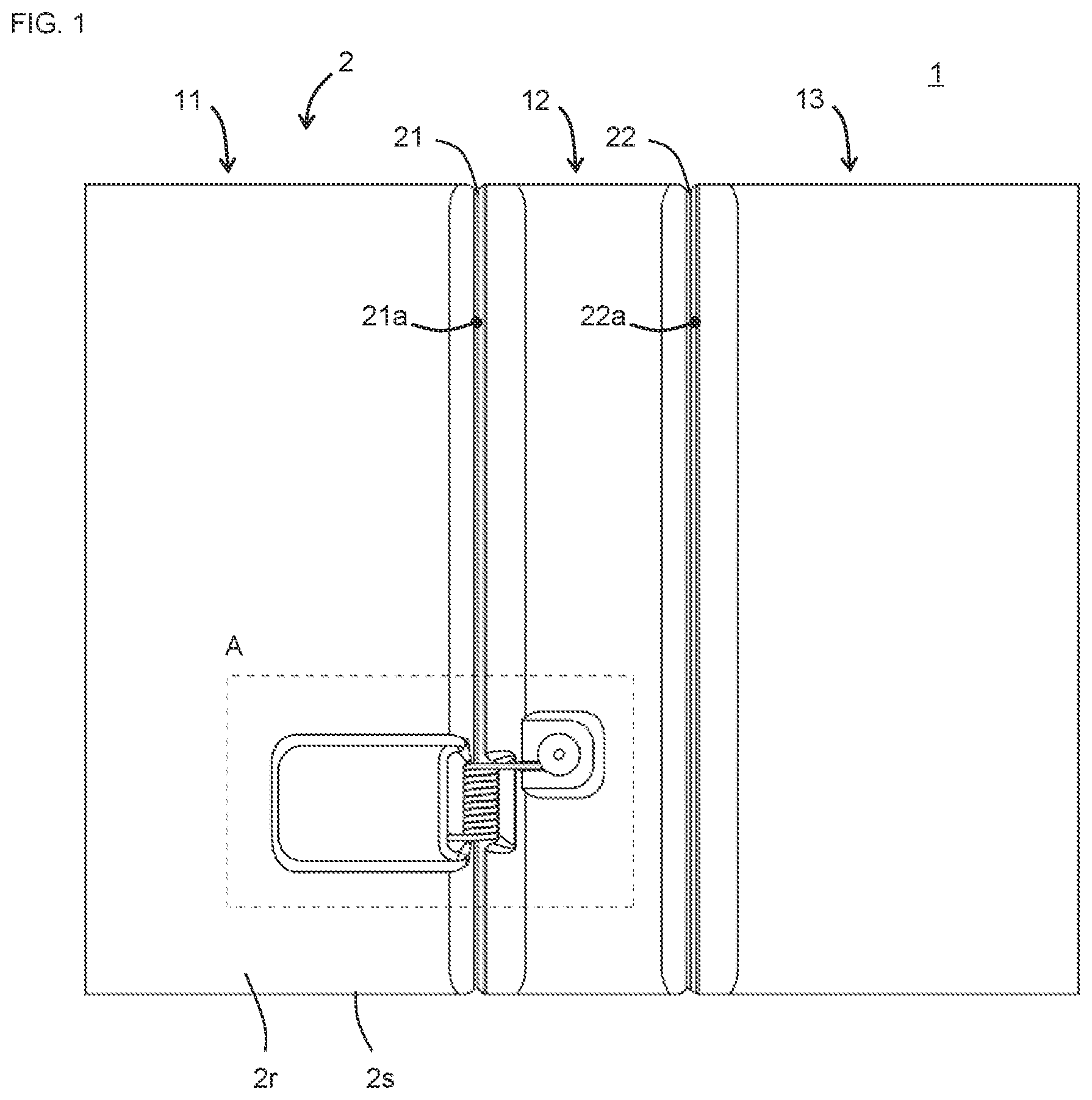
is a plan view of a structure 1 according to the first embodiment of the present invention.
is an enlarged view of an area A in .
is a cross-sectional view taken along B-B in .
is a cross-sectional view taken along C-C in .
is a view showing a state in which a blind rivet 5 is removed from .
is a view of a structure 1 according to the second embodiment of the present invention, corresponding to .
is a cross-sectional view taken along B-B in .
is a cross-sectional view taken along C-C in .
is a view showing a state in which a blind rivet 5 and a plate 6 are removed from .
DESCRIPTION OF EMBODIMENTS
Embodiments of the present invention will be described below with reference to the drawings. The various features of the embodiments shown below can be combined with each other. In addition, the invention can be made independently for each feature.
1. First Embodiment
The structure 1 according to the first embodiment of the present invention will be described with reference to to . The structure 1 can be used as a luggage board or the like installed in the luggage compartment of a vehicle. As shown in to , the structure 1 has a board shape and comprises a resin-molded body 2 , a core material 3 , and a torsion spring 4 . The core material 3 is arranged inside the resin-molded body 2 . The core material 3 can be omitted if unnecessary.
As shown in and , the resin-molded body 2 comprises a front wall 2 f , a rear wall 2 r , and a peripheral wall 2 s . The front wall 2 f and the rear wall 2 r are spaced apart from each other, and the peripheries of the front wall 2 f and the rear wall 2 r are connected by the peripheral wall 2 s . The resin-molded body 2 can be formed, for example, by molding a pair of resin sheets made of polyolefin such as polypropylene. In addition, the core material 3 can be arranged inside the resin-molded body 2 by performing molding with the core material 3 arranged between the pair of resin sheets.
As shown in , the resin-molded body 2 comprises first to third plate-shaped portions 11 to 13 , and first and second hinge portions 21 and 22 . The plate-shaped portions 11 and 12 are rotatably coupled to each other with the hinge portion 21 . The plate-shaped portions 12 and 13 are rotatably coupled to each other with the hinge portion 22 . The plate-shaped portion 13 and the hinge portion 22 can be omitted if unnecessary. Also, the structure 1 may have three or more hinge portions.
As shown in and , the hinge portions 21 and 22 can be formed by making the rear wall 2 r concave toward the front wall 2 f to form hinge concave portions 21 a and 22 a and welding the rear wall 2 r and the front wall 2 f (preferably by welding and compressing). The hinge portions 21 and 22 are preferably integral hinges formed integrally with the plate-shaped portions 11 to 13 . The hinge concave portion 21 a is provided between a side wall 11 d on the side of the plate-shaped portion 11 and a side wall 12 d on the side of the plate-shaped portion 12 . The side walls 11 d and 12 d are formed by making the rear wall 2 r concave toward the front wall 2 f . It is preferable that the side walls 11 d and 12 d are tapered so that the space between them widens toward the rear wall 2 r side.
As shown in and , the torsion spring 4 comprises first and second arms 41 and 42 and a coil portion 43 provided therebetween. The coil portion 43 is arranged at a position adjacent to the hinge portion 21 . At least a part of the coil portion 43 is preferably arranged inside the hinge concave portion 21 a . In addition, the side wall 12 d may be provided with a housing concave portion 12 e connected to the hinge concave portion 21 a , and the coil portion 43 may be arranged so as to span the hinge concave portion 21 a and the housing concave portion 12 e . The torsion spring 4 is configured to generate a restoring force in the rotational direction by relatively rotating the arms 41 and 42 with respect to the central axis of the coil portion 43 . By the restoring force of the torsion spring 4 , for example, a restoring force is generated so as to transition from a state in which the plate-shaped portion 11 is rotated with respect to the plate-shaped portion 12 in the direction indicated by an arrow X in (a state in which the front wall 2 f of the plate-shaped portion 11 is inclined with respect to the front wall 2 f of the plate-shaped portion 12 ) to the original state (a state in which the front wall 2 f of the plate-shaped portion 11 and the front wall 2 f of the plate-shaped portion 12 are flush with each other).
The arm 41 is slidably supported by the plate-shaped portion 11 . The arm 41 is slidably supported by being inserted into the plate-shaped portion 11 through an insertion hole 11 a provided in the plate-shaped portion 11 . As shown in , the arm 41 comprises a base portion 41 a and a tip portion 41 b . The base portion 41 a is a part that connects the coil portion 43 and the tip portion 41 b . The base portion 41 a is preferably linear. In this case, the base portion 41 a can easily slide with respect to the insertion hole 11 a . The base portion 41 a preferably has a length such that it does not come off even when the plate-shaped portion 11 rotates with respect to the plate-shaped portion 12 . The tip portion 41 b is a part in the vicinity of the tip, and is preferably linear. The angle of the tip portion 41 b with respect to the base portion 41 a is preferably 45 to 90 degrees, preferably 60 to 90 degrees. In this case, the arm 41 is restrained from coming out of the insertion hole 11 a . Specifically, this angle is, for example, 45, 50, 55, 60, 65, 70, 75, 80, 85, 90 degrees, and may be within a range between any two of the numerical values exemplified here.
As shown in and , in the plate-shaped portion 11 , it is preferable that the core material 3 does not exist in the part 11 b into which the arm 41 is inserted. This is because if the core material 3 exists in this part 11 b , it is difficult to insert the arm 41 , and the arm 41 may be caught by the core material 3 and the arm 41 may not slide smoothly.
The rear wall 2 r of the plate-shaped portion 11 is provided with a contact concave portion 11 c at a part facing the arm 41 in the plate-shaped portion 11 . The contact concave portion 11 c can be formed by making the rear wall 2 r of the plate-shaped portion 11 concave toward the front wall 2 f . By providing the contact concave portion 11 c , the base portion 41 a of the arm 41 easily contacts the inner surface of the rear wall 2 r . If the base portion 41 a is separated from the rear wall 2 r , the restoring force of the torsion spring 4 concentrates on the edge of the insertion hole 11 a , which may cause the insertion hole 11 a to widen. By providing the contact concave portion 11 c and bringing the base portion 41 a close to or in contact with the rear wall 2 r , the restoring force of the torsion spring 4 can be received by being distributed over a wide range of the rear wall 2 r , and thereby the widening of the insertion hole 11 a can be suppressed.
Thus, in the present embodiment, since the arm 41 is slidably supported on the plate-shaped portion 11 simply by inserting the arm 41 into the insertion hole 11 a , the number of fixation tools (screws, blind rivets, etc.) inserted into the plate-shaped portion 11 to support the arm 41 is zero, and the number of members for supporting the arm 41 is also zero. Therefore, according to the present embodiment, it is possible to reduce the number of components.
The arm 42 is supported by the plate-shaped portion 12 . As shown in , the arm 42 comprises a base portion 42 a and a curved portion 42 b . The base portion 42 a is a part that connects the coil portion 43 and the curved portion 42 b . The curved portion 42 b is a curved part, preferably an arcuate part. When the curved portion 42 b is arcuate, the central angle of the arc of the curved portion 42 b is, for example, 90 to 270 degrees, preferably 150 to 210 degrees. The plate-shaped portion 12 comprises a guide groove 12 a and a rivet pilot hole 12 b . The guide groove 12 a is arranged inside a concave portion 12 f provided in the plate-shaped portion 12 . The guide groove 12 a comprises a base portion 12 a 1 and a tip portion 12 a 2 . The base portion 12 a 1 is a part for housing the base portion 42 a . The tip portion 12 a 2 is a part for housing the curved portion 42 b . Preferably, the rivet pilot hole 12 b is arranged at the tip portion 12 a 2 .
The base portion 42 a and the curved portion 42 b of the arm 42 are arranged in the base portion 12 a 1 and the tip portion 12 a 2 of the guide groove 12 a , respectively. As shown in , a blind rivet 5 can be attached to the rivet pilot hole 12 b . The blind rivet 5 comprises a hollow rivet body 5 a , a flange 5 b projecting radially outward from the rivet body 5 a , and a mandrel (not shown) that passes through the inside of the rivet body 5 a and is connected to the tip of the rivet body 5 a . When the mandrel is pulled out with the rivet body 5 a inserted into the rivet pilot hole 12 b , the rivet body 5 a expands radially outward, and the rear wall 2 r is sandwiched between the flange 5 b and the rivet body 5 a , and thereby the blind rivet 5 is attached to the pilot hole 12 b . In addition, by covering the curved portion 42 b with the flange 5 b , the arm 42 is prevented from coming off the plate-shaped portion 12 . With such a method, the arm 42 is non-slidably supported by the plate-shaped portion 12 . Also, the arm 42 may be slidably supported by the plate-shaped portion 12 .
2. Second Embodiment
The structure 1 according to the second embodiment of the present invention will be described with reference to to . The present embodiment is similar to the first embodiment, and the main difference is the difference in the method of supporting the arm 41 . The following description will focus on the differences.
In the present embodiment, the arm 41 is arranged along a guide groove 11 e provided on the outer surface of the rear wall 2 r of the plate-shaped portion 11 . As shown in and , the guide groove 11 e can be formed by making the rear wall 2 r of the plate-shaped portion 11 concave toward the front wall 2 f . As shown in , the arm 41 is slidably supported on the plate-shaped portion 11 by covering the guide groove 11 e with a plate 6 while the arm 41 is arranged inside the guide groove 11 e.
As shown in , the plate 6 can be fixed using one blind rivet 5 . The rear wall 2 r of the plate-shaped portion 11 is provided with a rivet pilot hole 11 f . The pilot hole 11 f is arranged at a position adjacent to the guide groove 11 e . The plate 6 has a through hole 6 a . When the mandrel (not shown) is pulled out with the rivet body 5 a inserted into the pilot hole 11 f , the rivet body 5 a expands radially outward, and the rear wall 2 r and the plate 6 are sandwiched between the flange 5 b and the rivet body 5 a , and thereby the plate 6 is fixed to the rear wall 2 r . The plate 6 is preferably a washer having a diameter larger than that of the flange 5 b and a size capable of covering the guide groove 11 e . Such washers are available inexpensively.
According to such a configuration, the number of fixation tools (screws, blind rivets, etc.) inserted into the plate-shaped portion 11 to support the arm 41 is one. In addition, the number of members (plate 6 and blind rivet 5 ) used to support the arm 41 is one. Therefore, according to the present embodiment, it is possible to reduce the number of components.
As shown in and , the guide groove 11 e preferably comprises first and second groove portions 11 e 1 and 11 e 2 parallel to each other and a connecting groove portion 11 e 3 that connects the groove portions 11 e 1 and 11 e 2 . The groove portions 11 e 1 and 11 e 2 are preferably linear. The arm 41 comprises first and second parts 41 c and 41 d parallel to each other and a connecting portion 41 e that connects the parts 41 c and 41 d . The parts 41 c and 41 d are preferably linear. The parts 41 c and 41 d are arranged inside the groove portions 11 e 1 and 11 e 2 , and when the arm 41 slides, the parts 41 c and 41 d can slide along the groove portions 11 e 1 and 11 e 2 . In addition, the connecting portion 41 e is arranged inside the connecting groove portion 11 e 3 , and when the arm 41 slides, the connecting portion 41 e can slide in the connecting groove portion 11 e 3 .
The plate 6 preferably covers both the groove portions 11 e 1 and 11 e 2 . The pilot hole 11 f is preferably arranged between the groove portions 11 e 1 and 11 e 2 , and is preferably arranged in the center between the groove portions 11 e 1 and 11 e 2 . In such a configuration, the restoring force of the torsion spring 4 is applied to the plate 6 and the blind rivet 5 fixing it via the parts 41 c and 41 d . Since the restoring force is applied to the left and right of the blind rivet 5 in a well-balanced manner, there is an advantage that the force applied to the blind rivet 5 is not biased.
DESCRIPTION OF THE REFERENCE NUMERAL
1 : structure, 2 : resin-molded body, 2 f : front wall, 2 r : rear wall, 2 s : peripheral wall, 3 : core material, 4 : torsion spring, 41 : first arm, 41 a : base portion, 41 b : tip portion, 41 c : first part, 41 d : first part, 41 e : connecting portion, 42 : second arm, 42 a : base portion, 42 b : curved portion, 43 : coil portion, 5 : blind rivet, 5 a : rivet body, 5 b : flange, 6 : plate, 6 a : through hole, 11 : first plate-shaped portion, 11 a : insertion hole, 11 b : part, 11 c : contact concave portion, 11 d : side wall, 11 e : guide groove, 11 e 1 : first groove portion, 11 e 2 : second groove portion, 11 e 3 : connecting groove portion, 11 f : rivet pilot hole, 12 : second plate-shaped portion, 12 a : guide groove, 12 a 1 : base portion, 12 a 2 : tip portion, 12 b : rivet pilot hole, 12 d : side wall, 12 e : housing concave portion, 12 f : concave portion, 13 : third plate-shaped portion, 21 : first hinge portion, 21 a : hinge concave portion, 22 : second hinge portion, 22 a : hinge concave portion, A: area, X: arrow.
Figures (9)
Citations
This patent cites (12)
- US1084111
- US2002/0095883
- US2008/0121778
- US2008/0135716
- US2010/0026031
- US2016/0032636
- US2016/0186474
- US2021/0180377
- US2023/0182644
- US2012-232653
- US2014-034369
- US2017-047833