Abstract
There is provided a binding machine for binding a first object and a second object by using a staple that includes a first leg portion, a second leg portion, and a main body portion that connects the first leg portion and the second leg portion and that opens toward a forward direction. The binding machine includes: a first displacement portion configured to displace the first leg portion so as to surround the first object; a second displacement portion configured to displace the second leg portion such that the second object is surrounded by the first leg portion, the second leg portion, and the main body portion; and a guide portion configured to guide the first object in a direction approaching the first leg portion.
Claims (12)
1 . A binding machine for binding a first object and a second object by using a staple that includes a first leg portion, a second leg portion, and a main body portion that connects the first leg portion and the second leg portion and that includes an opening between the first leg portion and the second leg portion, the binding machine comprising: a first displacement portion including a first insertion portion into which the first object can be inserted, and configured to displace the first leg portion so as to surround the first object inserted into the first insertion portion; a second displacement portion including a second insertion portion which is provided on a side of the opening with respect to the main body portion and into which the second object can be inserted, and configured to displace the second leg portion such that the second object inserted into the second insertion portion is surrounded by the first leg portion, the second leg portion, and the main body portion; and a magazine configured to accommodate a plurality of the staples, wherein the plurality of staples are stacked in a stacked direction, the first insertion portion includes a guide portion configured to guide the first object in a direction approaching the first leg portion by bringing into contact with the first object, and a first inner wall portion configured to support the first leg portion, the first inner wall portion is provided between the first insertion portion and the second insertion portion, and the guide portion includes a wall portion that is configured to approach the first leg portion toward the main body portion from the opening, the wall portion being provided at a position separated from the first leg portion in the stacked direction.
12 . A binding machine for binding a first object and a second object by using a staple that includes a first leg portion, a second leg portion, and a main body portion that connects the first leg portion and the second leg portion, and that includes an opening between the first leg portion and the second leg portion, the binding machine comprising: a first displacement portion including a first insertion portion into which the first object can be inserted, and configured to displace the first leg portion so as to surround the first object inserted into the first insertion portion; a second displacement portion including a second insertion portion which is provided on a side of the opening with respect to the main body portion and into which the second object can be inserted, and configured to displace the second leg portion such that the second object inserted into the second insertion portion is surrounded by the first leg portion, the second leg portion, and the main body portion; and a magazine configured to accommodate a plurality of the staples, wherein the plurality of staples are stacked in a stacked direction, the first insertion portion includes a guide portion configured to guide the first object in a direction approaching the first leg portion by bringing into contact with the first object, the guide portion is provided between the first insertion portion and the second insertion portion, and the guide portion includes a wall portion that is configured to approach the first leg portion toward the main body portion from the opening, the wall portion being provided at a position separated from the first leg portion in the stacked direction.
Show 10 dependent claims
2 . The binding machine according to claim 1 , wherein the wall portion is configured to intersect the first leg portion and is configured to extend from outside to inside of the first leg portion when viewed from the stacked direction.
3 . The binding machine according to claim 2 , wherein each of the wall portions is provided at one side and at another side with respect to the first leg portion in the stacked direction.
4 . The binding machine according to claim 1 , wherein the wall portion is displaceable in a direction separated from the first leg portion.
5 . The binding machine according to claim 1 , further comprising: a biasing portion configured to bias, toward the first leg portion, the first object that approaches the first leg portion along the wall portion.
6 . The binding machine according to claim 5 , wherein the first leg portion includes a first portion extending in a direction from the main body portion toward the opening, a bent portion that is bent and connected to the first portion, and a tip end portion connected to the bent portion, separated from the first portion, and extending in a direction from a region surrounded by the staple toward an outer side, and the biasing portion is configured to bias the first object toward the bent portion.
7 . The binding machine according to claim 6 , wherein the biasing portion includes a pressing surface for pressing the first object against the bent portion and an elastic body for pressing the pressing surface against the bent portion.
8 . The binding machine according to claim 7 , wherein the biasing portion is configured to retract the pressing surface by compressing the elastic body, and is configured to insert the first object into a region surrounded by the first portion, the bent portion, the tip end portion, the wall portion, and the pressing surface when viewed from the stacked direction by retracting.
9 . The binding machine according to claim 8 , wherein the first displacement portion includes the first inner wall portion configured to support the first portion, and the wall portion approaches the first inner wall portion as advancing in a direction from the opening toward the main body portion by forming an acute angle between the first inner wall portion and the wall portion when viewed from the stacked direction.
10 . The binding machine according to claim 1 , further comprising: a slider configured to operate the first displacement portion and the second displacement portion, wherein the first leg portion includes a first portion extending in a direction from the main body portion toward the opening, a bent portion that is bent and connected to the first portion, and a tip end portion connected to the bent portion, separated from the first portion, and extending in a direction from a region surrounded by the staple toward an outer side and the slider includes a restriction wall that moves in the direction from the main body portion toward the opening as the first displacement portion and the second displacement portion are operated, and that is configured to press, toward the bent portion, the first object guided in the direction approaching the first leg portion by the guide portion.
11 . The binding machine according to claim 1 , wherein at least a part of the guide portion constitutes a part of a region into which the first object is to be inserted.
Full Description
Show full text →
CROSS-REFERENCE TO RELATED APPLICATIONS
This application is based on Japanese Patent Application No. 2023-004113 filed on Jan. 13, 2023 and Japanese Patent Application No. 2023-190932 filed on Nov. 8, 2023, the contents of which are incorporated herein by way of reference.
TECHNICAL FIELD
The present disclosure relates to a binding machine and a binding method.
BACKGROUND ART
It is known that a plant and the like are bound with a wire or the like by using a binding tool such as a staple.
Patent Literature 1 describes an electric binding machine that includes a rechargeable power source detachably connected to a mounting shell. A binding machine described in Patent Literature 2 can perform binding by using the staple described in Patent Literature 1.
Patent Literature 2 describes an example of such a staple. The staple includes a pair of left and right arms and a convex protrusion provided between the arms.
•
• Patent Literature 1: Chinese Patent Application Publication No. 111903423 • Patent Literature 2: European Patent No. 1839482
Patent Literature 1 discloses a binding machine that binds a plant and the like using the staple disclosed in Patent Literature 1.
The staple and the like described in Patent Literature 2 restrain the relative movement of two objects, that is, a guide element (a first object) and a plant and the like (a second object), and thus the staple and the like correspond to a binding tool (a staple) for binding the two objects. Patent Literature 2 discloses that the plant and the like are inserted into a cavity provided in the binding tool when the binding is performed. However, Patent Literature 2 does not disclose a method for engaging a binding tool with a string or the like, which is a guide element, and thus does not consider the improvement of a work efficiency by engaging the guide element and the binding tool with each other easily or in a manner of being less likely to be disengaged from each other.
Therefore, an example of the object of the present disclosure is to provide a binding machine and a binding method for improving a work efficiency by engaging a guide element and a binding tool with each other easily or in a manner of being less likely to be disengaged from each other.
SUMMARY OF INVENTION
There is provided a binding machine for binding a first object and a second object by using a staple that includes a first leg portion, a second leg portion, and a main body portion that connects the first leg portion and the second leg portion and that opens toward a forward direction. The binding machine includes: a first displacement portion configured to displace the first leg portion so as to surround the first object; a second displacement portion configured to displace the second leg portion such that the second object is surrounded by the first leg portion, the second leg portion, and the main body portion; and a guide portion configured to guide the first object in a direction approaching the first leg portion.
The guide portion may include a wall portion that is configured to approach the first leg portion toward a rearward direction.
The wall portion may be provided at a position separated from the first leg portion in an up-down direction intersecting an opening direction of the staple.
The wall portion may be configured to intersect the first leg portion and is configured to extend from outside to inside of the first leg portion in a top view.
The wall portion may be provided in an upper direction and a lower direction with respect to the first leg portion.
The wall portion may be displaceable in a direction separated from the first leg portion.
The binding machine may further include: a biasing portion configured to bias, toward the first leg portion, the first object that approaches the first leg portion along the wall portion.
The first leg portion may include a first portion extending in the forward direction, a bent portion that is bent and connected to the first portion, and a tip end portion connected to the bent portion and extending in an outward direction separated from the first portion. The biasing portion may be configured to bias the first object toward the bent portion (in the forward direction).
The biasing portion may include a pressing surface for pressing the first object in the forward direction and an elastic body for pressing the pressing surface in the forward direction.
The biasing portion may be configured to retract the pressing surface by compressing the elastic body, and may be configured to insert the first object into a region surrounded by the first portion, the bent portion, the tip end portion, the wall portion, and the pressing surface in a top view by retracting.
The first displacement portion may include a first inner wall portion configured to support the first portion. The wall portion may approach the first inner wall portion as advancing in a rearward direction so as to form an acute angle with the first inner wall portion in the top view.
The binding machine may further include: a slider configured to operate the first displacement portion and the second displacement portion. The first leg portion may include a first portion extending in the forward direction, a bent portion that is bent and connected to the first portion, and a tip end portion connected to the bent portion and extending in an outward direction separated from the first portion. The slider may include a restriction wall that moves in the forward direction as the first displacement portion and the second displacement portion are operated, and that is configured to press, toward the bent portion, the first object guided in the direction approaching the first leg portion by the guide portion.
At least a part of the guide portion may constitute a part of a region into which the first object is to be inserted.
BRIEF DESCRIPTION OF DRAWINGS
A is a diagram illustrating an example of a staple before binding in a top view;
B is a diagram illustrating an example of the staple after the binding in the top view;
C is a diagram illustrating an example of the staple after the binding in a front view;
is a schematic diagram of a binding method using a binding machine according to an embodiment;
is a cross-sectional view of the binding machine according to the embodiment in a right side view;
A is a cross-sectional view of the binding machine according to the embodiment in the top view;
B is a cross-sectional view of the binding machine according to the embodiment in the front view;
C is a partially enlarged view of an upper portion of a grip of the binding machine cut along a B-B cross section in a bottom view according to the embodiment;
is a partially enlarged view (a perspective view) illustrating a front-end side of the binding machine according to the embodiment;
A is a perspective view of a driver according to the embodiment;
B is a plan view of the driver according to the embodiment in the top view;
A is a perspective view of a slider according to the embodiment;
B is a plan view of the slider according to the embodiment in the top view;
A is a partially enlarged view of a cross section of the binding machine according to the embodiment in a side view;
B is a partially enlarged view of a cross section of the binding machine according to the embodiment in a rear view;
is a partially enlarged view (a perspective cross-sectional view) illustrating a nut part and the like of the binding machine according to the embodiment;
is a cross-sectional view illustrating a detachment portion and the like of the binding machine according to the embodiment;
A is a partially enlarged view illustrating an initial state of the binding machine according to the embodiment in the front view;
B is a partially enlarged view illustrating the initial state of the binding machine according to the embodiment in the top view;
A is a partially enlarged view illustrating a plastic deformation start time of the binding machine according to the embodiment in the top view;
B is a partially enlarged view illustrating the plastic deformation start time of the binding machine according to the embodiment in a side view;
C is a partially enlarged perspective view illustrating a front end portion of the binding machine according to the embodiment;
is a perspective view of a contact member 24 (a claw member) according to the embodiment;
is a cross-sectional view in the front view during plastic deformation by the contact member 24 (the claw member) according to the embodiment;
is a perspective view of a second arm according to the embodiment;
A is a plan view of the second arm according to the embodiment;
B is a rear view of the second arm according to the embodiment;
A is a partially enlarged view illustrating a driver movement start time of the binding machine according to the embodiment in the front view;
B is a partially enlarged view illustrating the driver movement start time of the binding machine according to the embodiment in the top view;
is a partially enlarged view illustrating a state in which the separated staple is advanced by the binding machine according to the embodiment in the top view;
is a partially enlarged view illustrating a state in which the staple has passed through a first outer wall portion by the binding machine according to the embodiment in the top view;
is a partially enlarged view illustrating a state in which the staple has reached a displacement start position by the binding machine according to the embodiment in the top view;
A is a partially enlarged view illustrating the front end portion of the binding machine in the front view when a user inserts a first object into a first insertion portion and inserts a second object into a second insertion portion;
B is a partially enlarged view illustrating the front end portion of the binding machine in the top view when the user inserts the first object into the first insertion portion and inserts the second object into the second insertion portion;
A is a partially enlarged view illustrating the front end portion of the binding machine in the front view when the slider restarts advancing after the first object and the second object are inserted;
B is a partially enlarged view illustrating the front end portion of the binding machine in the top view when the slider restarts advancing after the first object and the second object are inserted;
A is a partially enlarged view illustrating the front end portion of the binding machine in the front view when the slider advances and a second leg portion is deformed;
B is a partially enlarged view illustrating the front end portion of the binding machine in the top view when the slider advances and the second leg portion is deformed;
A is a partially enlarged view illustrating the front end portion of the binding machine in the front view immediately before the slider most advances;
B is a partially enlarged view illustrating the front end portion of the binding machine in the top view immediately before the slider most advances;
A is a partially enlarged view and an enlarged perspective view of the front end portion of the binding machine in the front view after the slider starts retracting;
B is a partially enlarged view and an enlarged perspective view of the front end portion of the binding machine in the top view after the slider starts retracting;
C is a partially enlarged perspective view of the front end portion of the binding machine after the slider starts retracting;
A is a partially enlarged view and an enlarged perspective view of the front end portion of the binding machine in the front view when the slider further retracts;
B is a partially enlarged view and an enlarged perspective view of the front end portion of the binding machine in the top view when the slider further retracts;
C is a partially enlarged perspective view of the front end portion of the binding machine when the slider further retracts;
is a diagram illustrating an example of a staple before binding in a top view;
is a cross-sectional view of a binding machine according to an embodiment in a right side view;
is a perspective view of the binding machine according to the embodiment as viewed obliquely in an upward direction;
is a perspective view of a slider according to the embodiment;
A is a perspective view of a front end portion of the binding machine according to the embodiment as viewed from a forward direction;
B is a plan view of the front end portion of the binding machine according to the embodiment in the top view as viewed from the upward direction;
is a plan view of the binding machine according to the embodiment in the top view as viewed from the upward direction;
A is a plan view of the binding machine according to the embodiment in the top view as viewed from the upward direction;
B is a plan view of the binding machine according to the embodiment in a bottom view as viewed from a downward direction;
is a perspective view of a guide portion according to the embodiment;
is an exploded perspective view of an elastic structure in the embodiment;
is a plan view of the binding machine according to the embodiment in the top view as viewed from the upward direction;
A is a perspective view illustrating a state in which the staple is displaced by the binding machine according to the embodiment, as viewed from the forward direction;
B is a plan view illustrating a state in which the staple is displaced by the binding machine according to the embodiment, in the top view as viewed from the upward direction;
A is a plan view illustrating a state in which an object insertion region is displaced by the binding machine according to the embodiment, as viewed from the upward direction;
B is a plan view illustrating a state in which the object insertion region is displaced by the binding machine according to the embodiment, in the bottom view as viewed from the downward direction;
is a plan view illustrating a state in which a second arm of the binding machine according to the embodiment rotates, as viewed from an upward direction Z 1 ;
is a rear view of the second arm of the binding machine according to the embodiment; and
is a rear view of the second arm of the binding machine according to the embodiment.
A is a plan view of a staple according to an embodiment;
B is a plan view of the staple according to the embodiment;
is a right side view of a binding machine according to the embodiment;
is a cross-sectional view of the binding machine according to the embodiment in a top view;
is a perspective view of a front end portion of the binding machine according to the embodiment;
A is a plan view of the front end portion of the binding machine according to the embodiment;
B is a perspective view of the front end portion of the binding machine according to the embodiment as viewed from an upward direction;
C is a perspective view of the front end portion of the binding machine according to the embodiment as viewed from a downward direction;
A is a plan view illustrating a binding method of the binding machine according to the embodiment;
B is a plan view illustrating the binding method of the binding machine according to the embodiment;
C is a plan view illustrating the binding method of the binding machine according to the embodiment;
D is a plan view illustrating the binding method of the binding machine according to the embodiment;
E is a plan view illustrating the binding method of the binding machine according to the embodiment;
F is a plan view illustrating the binding method of the binding machine according to the embodiment; and
is a perspective view of the binding machine according to the embodiment as viewed from a rearward direction.
DESCRIPTION OF EMBODIMENTS
Hereinafter, embodiments of the present disclosure will be described with reference to the drawings. The following embodiments are examples for explaining the present disclosure, and it is not intended to limit the present disclosure only to the embodiments.
Configuration of Staple S
First, a configuration of a staple S according to the present embodiment will be described. The staple S is formed of a plastic deformable wire material that has plasticity. The staple S may be referred to as a wire or a clip. The staple S includes, for example, a metal wire material or a metallic wire (including one whose surface is coated by using a plating process or a resin).
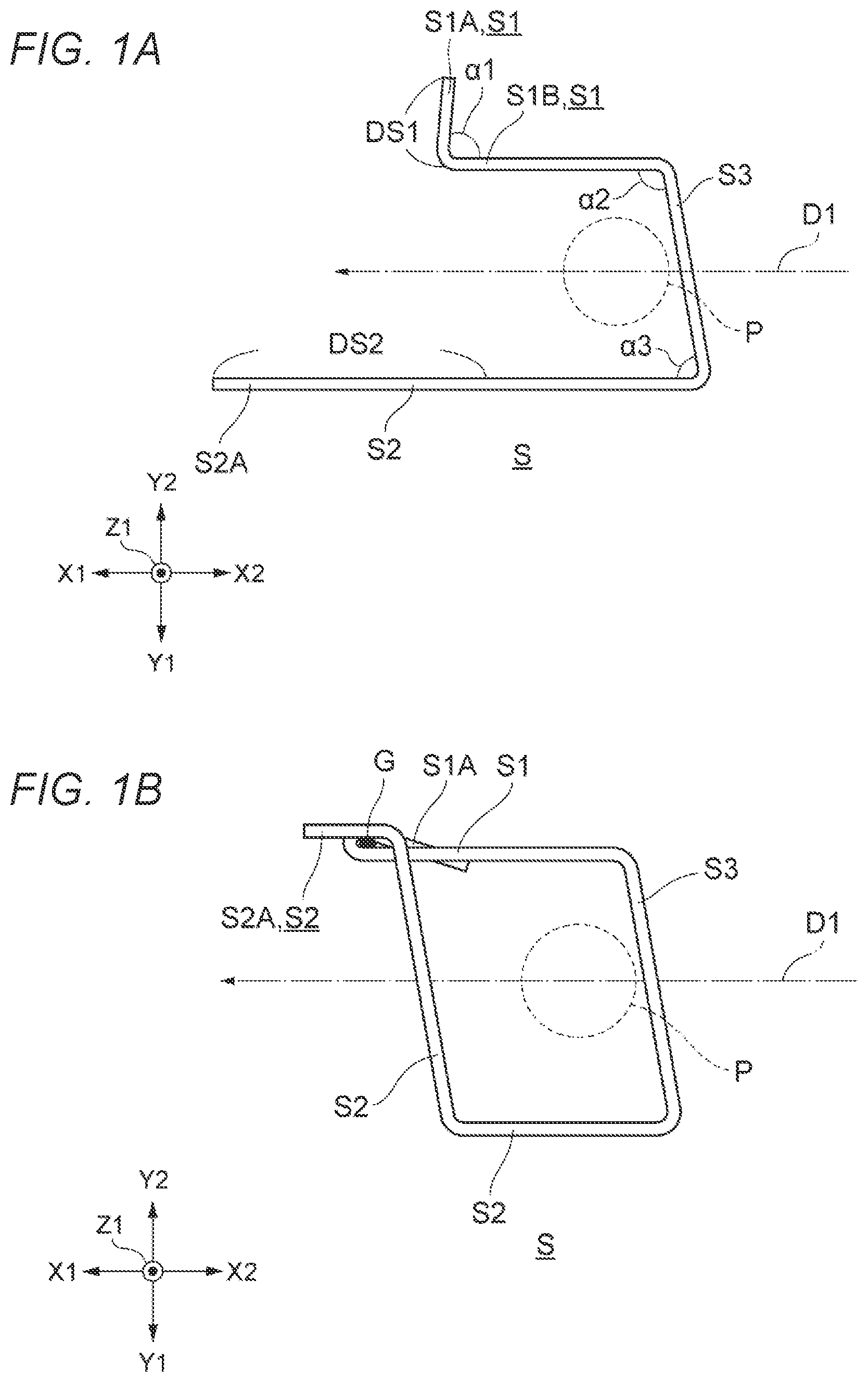
A illustrates the staple S before binding according to the present embodiment, and B and 1 C respectively illustrate a top view and a front view of the staple S in a bound state after the binding (however, for convenience of description, parts unnecessary for description such as a first object G and a second object P are omitted in C ).
The staple S includes a first leg portion S 1 , a second leg portion S 2 , and a main body portion S 3 connecting the first leg portion S 1 and the second leg portion S 2 .
In a state before the binding, the first leg portion S 1 and the second leg portion S 2 of the staple S are separately provided, and thus an opening is provided between the first leg portion S 1 and the second leg portion S 2 . A direction from a closed portion of the main body portion S 3 toward the opening (a leftward direction of a paper surface in A ) is referred to as an opening direction D 1 . When the staple S is set in a binding machine 10 , the opening direction D 1 of the staple S coincides with a forward direction X 1 to be described later.
The first leg portion S 1 is a portion including one end portion of the staple S, and includes a first portion S 1 B extending in the opening direction D 1 and a tip end portion S 1 A bent from the first portion S 1 B and extending outward. An angle formed by the first portion S 1 B and the tip end portion S 1 A is referred to as a bending angle α 1 , and a portion of the tip end portion S 1 A that is bent to be connected to the first portion S 1 B is referred to as a bent portion. In the present embodiment, the bending angle α 1 is 90 degrees or less.
The second leg portion S 2 is a portion including the other end portion of the staple S, and includes a second portion extending in the opening direction D 1 . In the top view ( B ) illustrating the bound state, the second leg portion S 2 is bent to intersect the first leg portion S 1 and closes the opening. Accordingly, the second leg portion S 2 according to the present embodiment is formed to be longer than a width of the opening, that is, a distance between the first leg portion S 1 and the second leg portion S 2 . In addition, the second leg portion S 2 is formed to be longer than the first leg portion S 1 .
The main body portion S 3 is a portion connecting the first leg portion S 1 and the second leg portion S 2 . The main body portion S 3 according to the present embodiment includes a side portion extending linearly. However, a shape of the main body portion S 3 is not limited thereto, and the main body portion S 3 may include, for example, a curved portion that is curved in an outward direction, or may include one or more side portions and one or more curved portions.
In the bound state illustrated in B , the tip end portion S 1 A of the first leg portion S 1 of the staple S is bent substantially clockwise (Hereinafter, in the top view, a substantially clockwise direction may be referred to as a “first rotation direction R 1 ”, and a substantially counterclockwise direction may be referred to as a “second rotation direction R 2 ”.) in B , and intersects the first leg portion S 1 in the top view. Accordingly, it is possible to sandwich the first object G with the first leg portion S 1 . As illustrated in C , the tip end portion S 1 A of the first leg portion S 1 is bent such that a tip end thereof advances toward a downward direction Z 2 separated from a plane PL penetrating through the first leg portion S 1 , the second leg portion S 2 , and the main body portion S 3 before the binding.
On the other hand, a part of the second leg portion S 2 of the staple S closes the opening by being folded in the first rotation direction R 1 . Since the opening is closed, it is possible to restrain the staple S from being disengaged from the second object P surrounded by the staple S. Further, as illustrated in C , a tip end portion S 2 A of the second leg portion S 2 is bent such that a tip end thereof advances in an upward direction Z 1 separated from the plane PL penetrating through the first leg portion S 1 , the second leg portion S 2 , and the main body portion S 3 before the binding. In this way, the tip end of the first leg portion S 1 is bent to advance in the downward direction Z 2 and is engaged with the first object G, and the tip end of the second leg portion S 2 is bent to advance in the upward direction Z 1 and is engaged with the second object P, and thus it is possible to easily generate tension in a region from an engagement position of the first object G with the first leg portion S 1 to an engagement position of the second object P with the second leg portion S 2 . Accordingly, it is possible to restrain the first object G from being bent and the staple S from falling off and the like.
In addition, the second leg portion S 2 is folded to a position at which the second leg portion S 2 intersects the first leg portion S 1 in the first rotation direction R 1 toward an inward direction of the staple S so as to close the opening in the top view. At this time, the tip end portion S 2 A of the second leg portion S 2 passes through a gap between the first object G and the second object P. Thereafter, the second leg portion S 2 is displaced in the second rotation direction R 2 opposite to the first rotation direction R 1 in the top view, which causes the tip end portion S 2 A of the second leg portion S 2 passing through the gap between the first object G and the second object P to be engaged with the first object G. As a result, the first object G can be engaged so as to be sandwiched between the tip end portion S 1 A of the first leg portion S 1 and the tip end portion S 2 A of the second leg portion S 2 . Even when the second object P grows, the first leg portion S 1 and the second leg portion S 2 are respectively bent in directions in which a force for sandwiching the first object G is strengthened. Accordingly, even when the second object P grows, the staple S is less likely to be disengaged from the first object G.
When the second leg portion S 2 is displaced in the first rotation direction R 1 , it is preferable to bend the second leg portion S 2 in the first rotation direction R 1 and bend the tip end portion S 2 A of the second leg portion S 2 in the second rotation direction R 2 opposite to the first rotation direction R 1 . According to such a configuration, it is possible to easily engage the tip end portion S 2 A of the second leg portion S 2 with the first object G by displacing the tip end portion S 2 A of the second leg portion S 2 that has passed through the gap between the first object G and the second object P in the second rotation direction R 2 .
As is clear from a comparison between A illustrating the state of the staple S before the binding, and B and 1 C illustrating the state of the staple S after the binding, when a distance from the tip end of the first leg portion S 1 to the displaced portion of the first leg portion S 1 is set to a first distance DS 1 and a distance from the tip end of the second leg portion S 2 to the displaced portion of the second leg portion S 2 is set to a second distance DS 2 , the second distance DS 2 is larger than the first distance DS 1 , and for example, the second distance DS 2 is larger than twice the first distance DS 1 . In this way, by bending the staple S in a non-symmetrical manner, it is possible to suitably engage the second leg portion S 2 with the first object G held adjacently to the first leg portion S 1 .
Further, as illustrated in A , a boundary position between the displaced portion and a non-displaced portion of the first leg portion S 1 , which corresponds to a position from the tip end of the first leg portion S 1 by the first distance DS 1 , corresponds to a position advanced in the opening direction D 1 with respect to a boundary position between the displaced portion and a non-displaced portion of the second leg portion S 2 , which corresponds to a position from the tip end of the second leg portion S 2 by the second distance DS 2 .
According to such a configuration, when a slider 44 is advanced in the opening direction D 1 , it is possible to first start the displacement of the second leg portion S 2 , and start the displacement of the first leg portion S 1 after the displacement of the second leg portion S 2 is started. Therefore, it is possible to restrain a large load from being applied to the binding machine 10 at the same time.
A shape of the staple S is not limited to that illustrated in A . For example, it will be understood by a person skilled in the art that the first leg portion S 1 and the second leg portion S 2 are not necessarily parallel to each other, and for example, even when the width of the opening becomes narrower toward the tip end, or the width of the opening becomes wider toward the tip end, it is possible to bend the staple S such that at least a part of the technical effects described above is exhibited. In addition, it will be understood by a person skilled in the art that even when the first leg portion S 1 and the second leg portion S 2 have the same length, the tip end of the first leg portion S 1 is surplus, but it is possible to bend the staple S such that at least a part of the technical effects described above is exhibited.
A method of bending the staple S is not limited to those illustrated in B and 1 C . For example, the tip end portion S 2 A of the second leg portion S 2 may not be bent. It will be understood by a person skilled in the art that even when the tip end portion S 2 A of the second leg portion S 2 is not bent, the second leg portion S 2 can be engaged with the first object G, and thus at least a part of the technical effects described above is exhibited.
An example of a configuration of the binding machine 10 for bending the staple S illustrated in A as illustrated in B and 1 C will be described below.
(A) to (E) of are schematic diagrams illustrating the configuration of the binding machine 10 according to the embodiment of the present disclosure and states of the staple S bent by the binding machine 10 , respectively. In (A) to (E) of , the main body portion S 3 of the staple S is static.
In order to describe a relation between relative directions, for the sake of convenience, a leftward direction of the paper surface in may be referred to as the forward direction X 1 , a rightward direction of the paper surface may be referred to as a rearward direction X 2 , a near-side direction perpendicular to the paper surface may be referred to as the upward direction Z 1 , a far-side direction perpendicular to the paper surface may be referred to as the downward direction Z 2 , a lower side of the paper surface may be referred to as a rightward direction Y 1 , and an upper side of the paper surface may be referred to as a leftward direction Y 2 . The top view refers to a viewpoint when the binding machine 10 and the like are seen from a position at the upward direction Z 1 toward the downward direction Z 2 , the front view refers to a viewpoint when the binding machine 10 and the like are seen from a position at the forward direction X 1 toward the rearward direction X 2 , and the side view refers to a viewpoint when the binding machine 10 and the like are seen toward the rightward direction Y 1 or the leftward direction Y 2 .
Further, when the staple S to be described later is set in the binding machine 10 , a direction from a region surrounded by the staple S (a region into which the second object P to be described later is inserted) toward an outer side of the staple S may be referred to as an outward direction, and a direction from the outer side of the staple S toward the region surrounded by the staple S may be referred to as an inward direction, with the staple S as a reference.
As illustrated in (A) of and the like, the binding machine 10 includes the slider 44 as an example of a movement part that moves in the forward direction X 1 . The binding machine 10 further includes a first displacement portion 20 for displacing the first leg portion S 1 of the staple S. The first displacement portion 20 displaces the first leg portion S 1 of the staple S so as to be engageable with the first object G by moving different parts in different directions based on the movement of the slider 44 toward the forward direction X 1 .
The slider 44 may be integrally formed or may be composed of a plurality of parts that move in an interlocked manner.
The first displacement portion 20 according to the present embodiment includes a contact member 24 that moves in a direction inclined toward the inward direction of the staple S (the rightward direction Y 1 ) and the rearward direction X 2 based on the movement of the slider 44 toward the forward direction X 1 . The contact member 24 comes into contact with a region of the tip end portion S 1 A of the staple S and bends the tip end portion S 1 A to plastically deform, and thus the contact member 24 may be referred to as a gripping portion.
The first displacement portion 20 may include a part that moves in a direction substantially perpendicular to the forward direction X 1 , which is the inward direction of the staple S (the rightward direction Y 1 ), based on the movement of the slider 44 toward the forward direction X 1 so as to come into contact with the tip end portion S 1 A of the staple S and bend the tip end portion S 1 A.
Instead of this, the first displacement portion 20 may include a part that moves in the outward direction of the staple S (the leftward direction Y 2 ) based on the movement of the slider 44 toward the forward direction X 1 so as to come into contact with the tip end portion S 1 A of the staple S and bend the tip end portion S 1 A.
Instead of this, the first displacement portion 20 may include a part that moves the staple S in the first rotation direction R 1 based on the movement of the slider 44 toward the forward direction X 1 so as to come into contact with the tip end portion S 1 A of the staple S and bend the tip end portion S 1 A.
Instead of this, the first displacement portion 20 may include a part that moves the staple S in the second rotation direction R 2 based on the movement of the slider 44 toward the forward direction X 1 so as to come into contact with the tip end portion S 1 A of the staple S and bend the tip end portion S 1 A.
As a mechanism for moving the parts such as the contact member 24 in different directions based on the movement of the movement part such as the slider 44 toward the forward direction X 1 , a mechanism disclosed in the present embodiment or other mechanisms may be used.
As a mechanism for rotating the parts such as the contact member 24 in the first rotation direction R 1 or the second rotation direction R 2 based on the movement of the movement part such as the slider 44 toward the forward direction X 1 , the mechanism disclosed in the present embodiment or other mechanisms may be used.
The binding machine 10 further includes a second displacement portion 30 for displacing the second leg portion S 2 of the staple S. The second displacement portion 30 displaces the second leg portion S 2 of the staple S so as to be engageable with the first object G by moving different parts in different directions based on the movement of the slider 44 toward the forward direction X 1 .
The second displacement portion 30 according to the present embodiment includes an arm (may also referred to as a second arm) that bends the second leg portion S 2 to plastically deform by rotating in the first rotation direction R 1 based on the movement of the slider 44 toward the forward direction X 1 . In the present embodiment, since the arm comes into contact with the second leg portion S 2 of the staple S and bends the second leg portion S 2 in a direction inclined toward the upward direction Z 1 while bending the second leg portion S 2 in a direction approaching the first leg portion S 1 , and thus the arm may be referred to as an obliquely bending portion.
In (A) of , the second displacement portion 30 is connected to the slider 44 and rotates with a front end portion of the slider 44 as a fulcrum. However, as described in an embodiment to be described later, the second displacement portion 30 may not be connected to the slider 44 . For example, the second displacement portion 30 may be not connected to the slider 44 , and may include a second arm 32 that bends the second leg portion S 2 to plastically deform the second leg portion S 2 by rotating in the first rotation direction R 1 by a second front end portion 44 A 2 of the slider 44 .
The second displacement portion 30 may include a part that moves in a direction substantially perpendicular to the forward direction X 1 , which is the inward direction of the staple S (the leftward direction Y 2 ), based on the movement of the slider 44 toward the forward direction X 1 so as to come into contact with the second leg portion S 2 of the staple S and bend the second leg portion S 2 .
Instead of this, the second displacement portion 30 may include a part that moves in the outward direction of the staple S (the rightward direction Y 1 ) based on the movement of the slider 44 toward the forward direction X 1 so as to come into contact with the second leg portion S 2 of the staple S and bend the second leg portion S 2 .
Instead of this, the second displacement portion 30 may include a part that moves the staple S in the second rotation direction R 2 based on the movement of the slider 44 toward the forward direction X 1 so as to come into contact with the second leg portion S 2 of the staple S and bend the second leg portion S 2 .
Further, the second displacement portion 30 according to the present embodiment additionally includes a support wall portion 68 A that bends the tip end portion S 2 A of the second leg portion S 2 in an opposite direction (the outward direction) by causing the tip end portion S 2 A of the second leg portion S 2 to pass therethrough while bringing the tip end portion S 2 A into contact therewith. Since the support wall portion 68 A bends the tip end portion S 2 A of the second leg portion S 2 , the support wall portion 68 A may be referred to as a tip end-bending portion.
However, in the case of using a staple having a tip end portion bent in the outward direction in advance, the binding machine may not include the support wall portion 68 A.
Further, the binding machine 10 according to the present embodiment additionally includes a fulcrum 66 A functioning as a bending fulcrum of the second leg portion S 2 . In the present embodiment, a front end of a second inner wall portion 66 functions as the fulcrum 66 A. In addition, a distance from a portion of the second leg portion S 2 , which is in contact with the fulcrum 66 A, to the tip end thereof corresponds to the second distance DS 2 .
(A) of is a schematic diagram illustrating a state immediately after the start of the bending of the staple S in the top view. As illustrated in (A) of , the second displacement portion 30 starts rotating in the first rotation direction R 1 by the slider 44 moving in the forward direction. Therefore, the second leg portion S 2 of the staple S that is in contact with the second displacement portion 30 starts bending with the fulcrum 66 A as a fulcrum. At the same time, the tip end portion S 2 A of the second leg portion S 2 passes through the support wall portion 68 A while being in contact with the support wall portion 68 A. Accordingly, it is possible to bend the tip end portion S 2 A of the second leg portion S 2 in the second rotation direction R 2 corresponding to the outward direction of the staple S while bending the second leg portion S 2 in the first rotation direction R 1 corresponding to the inward direction of the staple S.
(B) and (C) of are schematic diagrams respectively illustrating the states after the start of the bending of the staple S in the top view. As illustrated in (B) and (C) of , the second displacement portion 30 further rotates in the first rotation direction R 1 by the slider 44 further moving in the forward direction. Therefore, the second displacement portion 30 further bends the second leg portion S 2 in the first rotation direction R 1 with the fulcrum 66 A as a fulcrum.
(D) of is a schematic diagram illustrating a state in which the second leg portion S 2 of the staple S is bent and intersects the first leg portion S 1 in the top view. In the present embodiment, since the second leg portion S 2 is bent in the direction inclined toward the upward direction Z 1 while being bent in the direction approaching the first leg portion S 1 , the second leg portion S 2 does not intersect the first leg portion S 1 . As illustrated in (D) of , since the second displacement portion 30 further rotates in the first rotation direction R 1 by the slider 44 further moving in the forward direction and rotates by 90 degrees or more, the second displacement portion 30 can bend the second leg portion S 2 to the position at which the second leg portion S 2 intersects the first leg portion S 1 in the top view.
(E) of is a schematic diagram illustrating a state in which the first leg portion S 1 of the staple S is bent in the top view. As illustrated in (E) of , the contact member 24 of the first displacement portion 20 moves in the direction inclined toward the inward direction (the rightward direction Y 1 ) and the rearward direction X 2 by the slider 44 moving in the forward direction, and bends the tip end portion S 1 A of the first leg portion S 1 . As illustrated in (E) of , the tip end portion S 1 A may be folded in the upward direction Z 1 or may be folded in the downward direction Z 2 with respect to the first leg portion S 1 . By bending the tip end portion S 1 A of the first leg portion S 1 in this manner, it is possible to sandwich the first object G with the first leg portion S 1 .
Further, in the present embodiment, by disposing the first displacement portion 20 and the second displacement portion 30 such that a timing at which the first displacement portion 20 comes into contact with the slider 44 and a timing at which the second displacement portion 30 comes into contact with the slider 44 are different, a timing at which the bending of the first leg portion S 1 of the staple S starts and a timing at which the bending of the second leg portion S 2 of the staple S starts are deviated. According to such a configuration, it is possible to restrain a large load from being simultaneously generated in the binding machine 10 . In addition, by first starting the bending of the second leg portion S 2 having a large bending amount, it is possible to restrain a large deviation between a timing at which the bending of the first leg portion S 1 ends and a timing at which the bending of the second leg portion S 2 ends.
First Embodiment
Hereinafter, the detailed configuration of the binding machine 10 according to a first embodiment will be described.
is a cross-sectional view of the binding machine 10 in a right side view. A is a cross-sectional view of the binding machine 10 in the top view (However, for the sake of convenience, A is rotated by 90 degrees. Hereinafter, the drawings may be rotated in the same manner for the sake of convenience. Further, configurations not described in order to make the description easier to understand (for example, a housing of the binding machine 10 ) are omitted (hereinafter, some configurations may be omitted in the drawings for the same reason)).
B is a cross-sectional view of the binding machine 10 in the front view, which is obtained by cutting the binding machine 10 along an A-A cross section in A . is an enlarged perspective view of a front end portion of the binding machine 10 .
Schematic Configuration of Binding Machine 10
The binding machine 10 binds the first object G and the second object P by using the staple S having the formed opening. The configuration of the staple S ( A and 1 B ) according to the embodiment is described above.
The first object G is, for example, a wire, a beam, a string, a rod, a pipe, or a branch of a tree. The first object G may be referred to as a guide element. The second object P is, for example, a stem, a vine, a branch, or a fruit of a plant or a tree. The binding machine 10 restricts the movement of the second object P with respect to the first object G and binds the first object G and the second object P by displacing the first leg portion S 1 of the staple S so as to engage with the first object G, and displacing the second leg portion S 2 thereof so as to engage with the first object G such that the staple S surrounds the second object P.
The binding machine 10 includes the first displacement portion 20 that displaces the first leg portion S 1 of the staple S so as to be engageable with the first object G, and the second displacement portion 30 that displaces the second leg portion S 2 of the staple S so as to be engageable with the first object G. The second displacement portion 30 can bind the first object G and the second object P by engaging the tip end portion S 2 A of the second leg portion S 2 with the first object G in a state in which the second object P is surrounded by the first leg portion S 1 , the second leg portion S 2 , and the main body portion S 3 of the staple S.
More specifically, the binding machine 10 includes a grip 12 extending in an up-down direction so as to be gripped by a user and provided with a switch for driving the binding machine 10 , a magazine 14 ( ) that can accommodate a plurality of staples S stacked in the up-down direction, a pusher 16 that biases the plurality of staples S accommodated in the magazine 14 toward the upward direction Z 1 , a driver 42 that pushes the staple S positioned at an upper end toward the forward direction X 1 to separate the staple S positioned at the upper end from another staple S and move the staple S in the forward direction X 1 , a movement mechanism for moving the driver 42 and the slider 44 , the first displacement portion 20 for displacing the first leg portion S 1 of the staple S by the slider 44 , the second displacement portion 30 for displacing the second leg portion S 2 of the staple S by the slider 44 , and a detachment portion 56 that provides a movement path when the staple S is detached from the another staple S.
Here, the first displacement portion 20 includes a first outer wall portion 62 and a first inner wall portion 64 for displacing the tip end portion S 1 A by the tip end portion S 1 A of the first leg portion S 1 passing through the first outer wall portion 62 and the first inner wall portion 64 while being in contact therewith when the staple S moves in the forward direction X 1 by the driver 42 .
Further, the first displacement portion 20 includes a first arm 22 that rotates by being pushed by a first front end portion 44 A 1 of the slider 44 moving in the forward direction X 1 , and the contact member 24 that bends the tip end portion S 1 A of the first leg portion S 1 by moving toward the inward direction of the staple S while being in contact with the tip end portion S 1 A of the first leg portion S 1 as the first arm 22 rotates. The contact member 24 may be referred to as a claw member.
The second displacement portion 30 includes the second arm 32 that rotates by being pushed by the second front end portion 44 A 2 of the slider 44 moving in the forward direction X 1 . The second arm 32 can bend the second leg portion S 2 by rotating while being in contact with the second leg portion S 2 of the staple S. At this time, as described above, since the second object P is surrounded by the first leg portion S 1 , the second leg portion S 2 , and the main body portion S 3 of the staple S, and the second leg portion S 2 is engaged with the first object G, it is possible to bind the first object G and the second object P.
The binding machine 10 according to the present embodiment respectively displaces the first leg portion S 1 and the second leg portion S 2 of the staple S by moving the parts such as the slider 44 in a translational motion toward the forward direction X 1 and pushing the first arm 22 and the second arm 32 by the parts in the translational motion to convert the translational motion into a rotational motion. However, a means for displacing the first leg portion S 1 or the second leg portion S 2 is not limited thereto. For example, as the means for displacing the first leg portion S 1 , a means for displacing the tip end portion S 1 A in an arc shape when the tip end portion S 1 A of the first leg portion S 1 advances by the driver 42 or the slider 44 may be mounted. In addition, another means for converting the translational motion into the rotational motion may be adopted as a configuration for converting the translational motion into the rotational motion. Further, in the present embodiment, the first arm 22 and the second arm 32 are rotated together in the same direction in the top view to displace the first leg portion S 1 and the second leg portion S 2 , but the present disclosure is not limited thereto, for example, the second arm 32 may rotate in the opposite direction to displace the second leg portion S 2 .
Hereinafter, the detailed configuration of the binding machine 10 according to the present embodiment will be described.
Movement Mechanism (Feeding Mechanism) of Driver and Slider
The driver 42 of the binding machine 10 has a function of moving in the forward direction X 1 to move the staple S in the forward direction X 1 . The driver 42 moves the staple S positioned at the upper end, which is connected to the another staple S, toward the forward direction X 1 so as to separate the staple S from the another staple S, and further displaces the tip end portion S 1 A of the first leg portion S 1 by moving the staple S toward the forward direction X 1 and causing the tip end portion S 1 A of the first leg portion S 1 to pass through the first outer wall portion 62 provided in the first displacement portion 20 while being in contact therewith.
A is a perspective view of the driver 42 according to the present embodiment, and B is a plan view of the driver 42 in the top view. As illustrated in A and 6 B , the driver 42 is formed in a plate shape, and includes a front end portion having a front end surface 42 S in contact with the main body portion S 3 of the staple S, and a rear end portion provided in the rearward direction X 2 with respect to the front end portion and having a protruded portion 42 C for driver protruding in the downward direction Z 2 .
The front end portion of the driver 42 includes the front end surface 42 S that conforms to the shape of the main body portion S 3 of the staple S and is provided to be inclined with respect to a front-rear direction.
Further, a left end of the front end portion of the driver 42 has a protruding end portion 42 B extending in the forward direction X 1 so as to have a wall surface extending in the forward direction X 1 in order to support the first leg portion S 1 by coming into contact with the first portion S 1 B of the first leg portion S 1 corresponding to a left end of the staple S and with a portion of the main body portion S 3 connected to the first leg portion S 1 from the leftward direction Y 2 which is the outward direction.
As illustrated in B and 8 B , the driver 42 is guided to move in the front-rear direction by being fitted into a recessed portion provided in a base 46 . Since an upper surface of the driver 42 is in contact with a bottom surface of the slider 44 fitted into the recessed portion provided in the base 46 , the movement of the driver 42 toward the upward direction Z 1 is restricted. In addition, since left and right side surfaces of the driver 42 are respectively in contact with left and right wall surfaces of the base 46 provided to extend in the front-rear direction, the leftward and rightward movement of the driver 42 is restricted. Further, the protruded portion 42 C for driver formed at the rear end portion of the driver 42 and protruding in the downward direction Z 2 is inserted into the recessed portion of the base 46 . Left and right wall surfaces and a bottom surface of the protruded portion 42 C for driver respectively face the wall surfaces and an upper surface of the base 46 . According to the above configuration, the driver 42 is guided to move in the front-rear direction.
Three grooves are formed in a bottom portion of the protruded portion 42 C for driver protruding toward the downward direction Z 2 . Specifically, a first groove 42 G 1 for moving toward the forward direction X 1 by being pushed toward the forward direction X 1 by a first claw portion 48 C 1 of a switching block 48 (an example of a “block”) to be described later, a second groove 42 G 2 for moving toward the rearward direction X 2 by being pushed toward the rearward direction X 2 by a second claw portion 48 C 2 , and a third groove 42 G 3 for moving toward the forward direction X 1 by being pushed toward the forward direction X 1 by a third claw portion 48 C 3 are formed. As illustrated in B and 8 B , the first groove 42 G 1 , the second groove 42 G 2 , and the third groove 42 G 3 are provided to be parallel to one another and extend in the front-rear direction. In addition, front ends of the first groove 42 G 1 and the third groove 42 G 3 (groove side surfaces of the first groove 42 G 1 and the third groove 42 G 3 facing the rearward direction X 2 ) are provided at the same position in the front-rear direction. In addition, a rear end of the second groove 42 G 2 (a groove side surface of the second groove 42 G 2 facing the forward direction X 1 ) is provided in the rearward direction X 2 with respect to the front ends of the first groove 42 G 1 and the third groove 42 G 3 (the groove side surfaces of the first groove 42 G 1 and the third groove 42 G 3 facing the rearward direction X 2 ). On the other hand, the first groove 42 G 1 and the third groove 42 G 3 are provided to extend in the rearward direction X 2 with respect to the rear end of the second groove 42 G 2 .
As will be described later, a configuration is adopted in which the driver 42 is advanced by using two grooves, that is, the first groove 42 G 1 and the third groove 42 G 3 at the time of advance, the driver 42 is retracted by using one groove, that is, the second groove 42 G 2 at the time of retraction, and thus the driver 42 can suitably move in the forward direction X 1 at the time of advance having a relatively high load. Further, in the top view, the second groove 42 G 2 is provided to overlap with a central axis of a ball screw 50 , and the first groove 42 G 1 and the third groove 42 G 3 are provided to sandwich the second groove 42 G 2 , and thus the driver 42 can advance and retract in a well-balanced manner.
The driver 42 is placed on the base 46 of the binding machine 10 and can move in the front-rear direction on the base 46 . Therefore, a part of the upper surface of the base 46 is exposed in the upward direction Z 1 by forming the first groove 42 G 1 , the second groove 42 G 2 , and the third groove 42 G 3 .
The slider 44 of the binding machine 10 has a function of moving in the forward direction X 1 and pushing the first displacement portion 20 and the second displacement portion 30 toward the forward direction X 1 so as to displace the first leg portion S 1 and the second leg portion S 2 of the staple S, respectively. The slider 44 according to the present embodiment includes the first front end portion 44 A 1 that pushes the first arm 22 of the first displacement portion 20 toward the forward direction X 1 to rotate the first arm 22 , and the second front end portion 44 A 2 that pushes the second arm 32 of the second displacement portion 30 toward the forward direction X 1 to rotate the second arm 32 .
A is a perspective view of the slider 44 according to the present embodiment, and B is a plan view of the slider 44 in the top view. As illustrated in A and 7 B , the slider 44 is formed in a plate shape, and includes the first front end portion 44 A 1 that extends in the forward direction X 1 on a left side on which the first leg portion S 1 of the staple S is disposed, and the second front end portion 44 A 2 that is separated from the first front end portion 44 A 1 and extends in the forward direction X 1 on a side on which the second leg portion S 2 of the staple S is disposed.
The slider 44 further includes fixing portions 44 B for being fixed to a nut part 52 to be described later by using bolts.
As illustrated in B , the slider 44 is guided to move in the front-rear direction by being fitted into the recessed portion provided in the base 46 . An upper surface of the slider 44 comes into contact with the base 46 or a guide fixed to the housing so as to restrict the movement toward the upward direction Z 1 . Further, left and right side surfaces of the slider 44 come into contact with the left and right wall surfaces of the base 46 provided to extend in the front-rear direction so as to restrict the leftward and rightward movement. Further, the bottom surface of the slider 44 is supported by the upper surface of the base 46 and the upper surface of the driver 42 . According to such a configuration, the slider 44 (and the driver 42 on which the slider 44 is stacked) is guided to move in the front-rear direction.
Configurations of the first front end portion 44 A 1 and the second front end portion 44 A 2 of the slider 44 will be described later.
The nut part 52 of the binding machine 10 (for example, A, 8 A, and 8 B ) has a function of moving the driver 42 and the slider 44 in the forward direction X 1 and the rearward direction X 2 . The nut part 52 according to the present embodiment is formed with a female screw that is screwed to a male screw of the ball screw 50 via a ball member (not shown). Therefore, the nut part 52 moves in the forward direction X 1 when the ball screw 50 rotates clockwise, and the nut part 52 moves in the rearward direction X 2 when the ball screw 50 rotates counterclockwise. The nut part 52 is fixed to the slider 44 . Further, as illustrated in A , a front end surface of the nut part 52 is in contact with a rear end surface of the slider 44 . Therefore, the nut part 52 and the slider 44 can integrally move in the forward direction X 1 and the rearward direction X 2 in a state in which a rotational moment is restrained.
Further, the nut part 52 includes an annular holding portion 52 A protruding in the downward direction Z 2 in order to hold the switching block 48 ( B ) provided with the first claw portion 48 C 1 , the second claw portion 48 C 2 , and the third claw portion 48 C 3 . The nut part 52 and the switching block 48 held by the nut part 52 can integrally move in the forward direction X 1 and the rearward direction X 2 . The holding portion 52 A holds the switching block 48 such that the first claw portion 48 C 1 can be inserted into the first groove 42 G 1 , the second claw portion 48 C 2 can be inserted into the second groove 42 G 2 , and the third claw portion 48 C 3 can be inserted into the third groove 42 G 3 .
The nut part 52 , the slider 44 , and the driver 42 can move in the forward direction X 1 and the rearward direction X 2 , and thus the nut part 52 , the slider 44 , and the driver 42 may be referred to as movement portions.
A is a partially enlarged view obtained by cutting the binding machine 10 along a vertical cross section including the central axis 50 AX of the ball screw 50 in a side view obtained by seeing the binding machine 10 from a side surface. B is a partially enlarged view obtained by cutting the binding machine 10 along a vertical cross section perpendicular to the central axis 50 AX of the ball screw 50 in a rear view obtained by seeing the binding machine 10 from the rearward direction X 2 . is a partially enlarged view illustrating the nut part 52 and the like in a perspective cross-sectional view of the binding machine 10 .
As illustrated in B , an elastic member 49 for generating an elastic force for pressing a bottom surface of the switching block 48 against the surface of the base 46 is inserted between the nut part 52 and the switching block 48 . Accordingly, the switching block 48 can move in the up-down direction, and a distance in the up-down direction between the nut part 52 and the switching block 48 varies according to a surface shape of the base 46 through which the switching block 48 passes.
In the present embodiment, the nut part 52 can move in the forward direction X 1 and the rearward direction X 2 by a motor 54 and the ball screw 50 .
The motor 54 ( A ) rotates the ball screw 50 . The motor 54 is provided at a rear end portion of the binding machine 10 . The binding machine 10 may include a battery that is detachably provided, and the motor 54 may be rotationally driven by a power source of the battery. The binding machine 10 according to the present embodiment further includes a speed reducer 55 , and the motor 54 increases a torque by the speed reducer 55 to rotate the ball screw 50 . In addition, a printed wiring board on which a CPU corresponding to a control device for controlling the motor 54 is mounted is mounted on the rear end portion of the binding machine 10 .
The ball screw 50 ( A, 8 A, and 8 B ) is provided by extending a substantially central portion of the binding machine 10 in the front-rear direction. As described above, the ball screw 50 is formed with the male screw that is screwed to the female screw of the nut part 52 via the ball member (not shown).
The base 46 ( B, 8 A, and 8 B ) supports the driver 42 and the slider 44 . As illustrated in B , the base 46 includes a support surface that comes into contact with or faces the bottom surface of the driver 42 so as to support the driver 42 from the downward direction Z 2 , and a wall portion extending in the front-rear direction in order to come into contact with or face the left side surface of the driver 42 so as to support the driver 42 from the leftward direction Y 2 . Further, the base 46 includes a wall portion extending in the front-rear direction in order to come into contact with or face a right end of the driver 42 so as to support the driver 42 from the rightward direction Y 1 . According to such a configuration, the base 46 guides the driver 42 to move in the front-rear direction.
Further, the base 46 includes a support surface that comes into contact with or faces the bottom surface of the slider 44 placed on the driver 42 so as to support the slider 44 from the downward direction Z 2 , and a wall portion extending in the front-rear direction in order to come into contact with or face a left end of the slider 44 so as to support the slider 44 from the leftward direction Y 2 . Further, the base 46 includes a wall portion extending in the front-rear direction in order to come into contact with or face a right end of the slider 44 so as to support the slider 44 from the rightward direction Y 1 . According to such a configuration, the base 46 guides the slider 44 to move in the front-rear direction.
As illustrated in , the base 46 is formed with a first protrusion 46 A 1 provided with a taper that protrudes in the upward direction Z 1 as advancing in the rearward direction X 2 , a second protrusion 46 A 2 provided with a taper that protrudes in the upward direction Z 1 as advancing in the forward direction X 1 , and a third protrusion 46 A 3 provided with a taper that protrudes in the upward direction Z 1 as advancing in the rearward direction X 2 .
The first protrusion 46 A 1 is provided on a path of the first claw portion 48 C 1 (inside the first groove 42 G 1 ) when the driver 42 moves in the rearward direction X 2 .
The second protrusion 46 A 2 is provided on a path of the second claw portion 48 C 2 (inside the second groove 42 G 2 ) when the driver 42 moves in the forward direction X 1 .
The third protrusion 46 A 3 is provided on a path of the third claw portion 48 C 3 (inside the third groove 42 G 3 ) when the driver 42 moves in the rearward direction X 2 .
Each of the first protrusion 46 A 1 to the third protrusion 46 A 3 is preferably formed to have the same height as the driver 42 (a plate thickness of the driver 42 ) or be higher than the driver 42 .
The first protrusion 46 A 1 and the third protrusion 46 A 3 are provided at the same position in the front-rear direction. The second protrusion 46 A 2 is provided in the forward direction X 1 with respect to the first protrusion 46 A 1 and the third protrusion 46 A 3 .
According to the above configuration, when the motor 54 rotates the ball screw 50 clockwise, the nut part 52 , the slider 44 fixed to the nut part 52 , and the switching block 48 held by the nut part 52 move together in the forward direction X 1 . Further, since the first claw portion 48 C 1 , the second claw portion 48 C 2 , and the third claw portion 48 C 3 of the switching block 48 are respectively inserted into the first groove 42 G 1 , the second groove 42 G 2 , and the third groove 42 G 3 , a front surface of the first claw portion 48 C 1 and a front surface of the third claw portion 48 C 3 respectively come into contact with a side surface of the first groove 42 G 1 facing the rearward direction X 2 and a side surface of the third groove 42 G 3 facing the rearward direction X 2 . Therefore, the switching block 48 pressed against the surface of the base 46 by the elastic member 49 moves the driver 42 in the forward direction X 1 by the front surface of the first claw portion 48 C 1 and the front surface of the third claw portion 48 C 3 while pressing the surface of the base 46 in the downward direction Z 2 . As a result, the driver 42 and the slider 44 move together in the forward direction X 1 . A moving operation in which the driver 42 and the slider 44 move together in the forward direction X 1 is referred to as a first moving operation.
Thereafter, when the switching block 48 advances to a position at which the second protrusion 46 A 2 is provided, the second claw portion 48 C 2 moves in the upward direction Z 1 along an inclined surface of the second protrusion 46 A 2 . Therefore, the switching block 48 moves in the upward direction Z 1 while moving in the forward direction X 1 . As a result, the front surface of the first claw portion 48 C 1 and the front surface of the third claw portion 48 C 3 move in the upward direction Z 1 with respect to the side surface of the first groove 42 G 1 and the side surface of the third groove 42 G 3 that are in contact with the front surface of the first claw portion 48 C 1 and the front surface of the third claw portion 48 C 3 , respectively. Accordingly, the switching block 48 moves on the driver 42 , and the driver 42 stops moving in the forward direction X 1 . At this time, the first moving operation ends.
After the first moving operation ends, when the motor 54 further rotates the ball screw 50 clockwise, the switching block 48 moves on the driver 42 in the forward direction X 1 . At this time, of the slider 44 and the driver 42 , only the slider 44 moves in the forward direction X 1 . A moving operation in which only the slider 44 of the driver 42 and the slider 44 moves in the forward direction X 1 is referred to as a second moving operation. When the slider 44 advances by a predetermined amount with respect to the driver 42 , the motor 54 stops the clockwise rotation of the ball screw 50 . At this time, the second moving operation ends.
During the second moving operation, there is a possibility that the driver 42 advances by the friction with the switching block 48 and the driver 42 . Therefore, the binding machine 10 may include a stopper for stopping the advance of the driver 42 during the second moving operation. For example, by adopting a configuration in which an opening hole is formed on the base 46 , the stopper such as a ball biased in the upward direction Z 1 from the opening hole is exposed, and on the other hand, a recess into which the ball is inserted is provided on the bottom surface of the driver 42 , and the stopper and the recessed portion are engaged with each other at a position at which the first moving operation ends and the movement of the driver 42 toward the forward direction X 1 is to be stopped, it is possible to restrain the advance and the retraction of the driver 42 during the second moving operation.
As will be described later, in the first moving operation, by pushing the staple S positioned at the upper end in the forward direction X 1 by using the driver 42 moving in the forward direction X 1 , it is possible to move the staple S positioned at the upper end in the forward direction X 1 and separate the staple S from the another staple S. Further, in the first moving operation, by bringing the tip end portion S 1 A of the first leg portion S 1 into contact with the first outer wall portion 62 while moving the staple S positioned at the upper end in the forward direction X 1 by using the driver 42 moving in the forward direction X 1 , it is possible to displace (plastically deform) the first leg portion S 1 such that the bending angle α 1 formed by the tip end portion S 1 A of the first leg portion S 1 and the first portion S 1 B of the first leg portion S 1 is further reduced.
Further, in the second moving operation, the driver 42 stops the movement toward the forward direction X 1 , and thus the staple S pushed by the driver 42 also stops the movement toward the forward direction X 1 . Accordingly, in a state in which the staple S is stopped, by causing the slider 44 to advance in the second moving operation, it is possible to push the second arm 32 of the second displacement portion 30 in the forward direction X 1 by the second front end portion 44 A 2 of the slider 44 so as to rotate, and displace the second leg portion S 2 of the staple S so as to be surrounded by the first leg portion S 1 , the second leg portion S 2 , and the main body portion S 3 and be engaged with the first object G. Further, in the state in which the staple S is stopped, by rotating the first arm 22 of the first displacement portion 20 by the first front end portion 44 A 1 of the slider 44 , it is possible to displace the first leg portion S 1 of the staple S so as to be engaged with the first object G.
The binding machine 10 may further include a sensor other than a Hall sensor for obtaining a rotation amount of the motor 54 in order to control movement amounts of the driver 42 and the slider 44 . In addition, the binding machine 10 may further include a magnet attached to the nut part 52 in order to detect and control a position of the nut part 52 in the front-rear direction, and a sensor other than a Hall sensor for obtaining a position of the magnet attached to the nut part 52 .
After a binding operation ends, when the motor 54 rotates the ball screw 50 counterclockwise, the nut part 52 , the slider 44 fixed to the nut part 52 , and the switching block 48 held by the nut part 52 move together in the rearward direction X 2 . At this time, the switching block 48 moves on the stopped driver 42 in the rearward direction X 2 .
Further, when the motor 54 rotates the ball screw 50 counterclockwise, the second claw portion 48 C 2 of the switching block 48 moves in the downward direction Z 2 while moving in the rearward direction X 2 along the inclined surface of the second protrusion 46 A 2 provided on the base 46 , and thus the first claw portion 48 C 1 , the second claw portion 48 C 2 , and the third claw portion 48 C 3 of the switching block 48 are respectively inserted into regions inside the first groove 42 G 1 , the second groove 42 G 2 , and the third groove 42 G 3 . In addition, when the motor 54 rotates the ball screw 50 counterclockwise, the switching block 48 moves in the rearward direction X 2 , and a rear surface of the second claw portion 48 C 2 of the switching block 48 comes into contact with a side surface of the second groove 42 G 2 facing the forward direction X 1 . Therefore, the switching block 48 moves the driver 42 in the rearward direction X 2 by the rear surface of the second claw portion 48 C 2 while pressing the surface of the base 46 in the downward direction Z 2 by the elastic member 49 . At this time, the nut part 52 , the slider 44 , the switching block 48 , and the driver 42 move together in the rearward direction X 2 .
Further, when the motor 54 rotates the ball screw 50 counterclockwise and the switching block 48 retracts to the position at which the first protrusion 46 A 1 and the third protrusion 46 A 3 are provided, the first claw portion 48 C 1 and the third claw portion 48 C 3 of the switching block 48 respectively move in the upward direction Z 1 along inclined surfaces of the first protrusion 46 A 1 and the third protrusion 46 A 3 . Therefore, the switching block 48 moves in the upward direction Z 1 while moving in the rearward direction X 2 . As a result, the rear surface of the second claw portion 48 C 2 moves in the upward direction Z 1 with respect to the side surface of the second groove 42 G 2 that is in contact with the rear surface of the second claw portion 48 C 2 . Accordingly, the switching block 48 moves on the driver 42 , and the driver 42 stops moving in the rearward direction X 2 . In order to restrict the movement of the driver 42 toward the rearward direction X 2 , the binding machine 10 may include a stopper having the above configuration or other configurations.
Thereafter, when the motor 54 further rotates the ball screw 50 counterclockwise, the switching block 48 moves on the driver 42 in the rearward direction X 2 . At this time, of the driver 42 and the slider 44 , only the slider 44 moves in the rearward direction X 2 . When the slider 44 retracts by a predetermined amount with respect to the driver 42 , the motor 54 stops the counterclockwise rotation of the ball screw 50 .
Thereafter, when the motor 54 rotates the ball screw 50 clockwise, the nut part 52 , the slider 44 fixed to the nut part 52 , and the switching block 48 held by the nut part 52 move together in the forward direction X 1 . Since the nut part 52 , the slider 44 , and the switching block 48 are moved together in the forward direction X 1 to a position at which the first claw portion 48 C 1 and the third claw portion 48 C 3 of the switching block 48 respectively come into contact with or approach close to a side surface of the front end of the first groove 42 G 1 and a side surface of the front end of the third groove 42 G 3 , and thereafter, it is possible to shift to the first moving operation.
According to the above configuration, the binding machine 10 can execute the first moving operation in which the driver 42 and the slider 44 advance together, and the second moving operation in which only the slider 44 of the driver 42 and the slider 44 further moves in the forward direction X 1 .
A position of the nut part 52 in an initial state is not limited. For example, the binding machine 10 may have a configuration in which only the slider 44 moves in the forward direction immediately after startup from the initial state, and then the first moving operation in which the driver 42 and the slider 44 start moving is executed.
Feeding-Bending Mechanism of Detachment Portion
The detachment portion includes a support wall that supports the staple S in the movement path of the staple S separated by the driver 42 and moving in the forward direction X 1 and during the displacement by the first displacement portion 20 and the second displacement portion 30 .
As illustrated in , the detachment portion 56 is provided to vertically move as the slider 44 moves. The detachment portion 56 is formed with a gap 56 A in which a part of the slider 44 enters as the slider 44 moves. Since a part of the slider 44 enters the gap 56 A of the detachment portion 56 , a vertical position of the detachment portion 56 can be stabilized, and the staple S can be reliably deformed.
A and 11 B are partially enlarged views illustrating the front end portion of the binding machine 10 in the initial state (a standby state) in the front view and the top view, respectively.
When the staple S moves in the forward direction X 1 by the driver 42 , the tip end portion S 1 A of the first leg portion S 1 passes through the first outer wall portion 62 while being in contact therewith, and thus the first outer wall portion 62 executes plastic deformation so as to further reduce the bending angle α 1 formed by the tip end portion S 1 A of the first leg portion S 1 and the first portion S 1 B of the first leg portion S 1 (a portion connected to the tip end portion S 1 A of the first leg portion S 1 ).
Accordingly, the first outer wall portion 62 is provided at a position at which only a part of the tip end portion S 1 A of the first leg portion S 1 of the staple S is in contact with the first outer wall portion 62 .
The first inner wall portion 64 is provided inside the first leg portion S 1 to support the first leg portion S 1 from the inside when the first leg portion S 1 of the staple S moves in the forward direction X 1 by the driver 42 and when the first leg portion S 1 is displaced. The first inner wall portion 64 includes a bottom surface provided along a movement path of the first leg portion S 1 , and a wall surface provided substantially parallel to the front-rear direction, which is a movement direction of the first leg portion S 1 , and supporting the first leg portion S 1 from the inside.
On the other hand, the first outer wall portion 62 is provided to include a wall surface inclined such that a gap with the wall surface of the first inner wall portion 64 becomes small toward the forward direction X 1 . According to such a configuration, it is possible to displace the tip end portion such that the bending angle α 1 becomes small as the tip end portion S 1 A of the first leg portion S 1 advances in the forward direction X 1 .
Further, the first outer wall portion 62 according to the present embodiment at least includes a first region 62 A ( ) at which a wall surface in which a gap with the wall surface of the first inner wall portion 64 is relatively largely reduced is formed, and a second region 62 B ( ) that is provided in the forward direction X 1 with respect to the first region 62 A and at which a wall surface in which a gap with the wall surface of the first inner wall portion 64 is slightly reduced is formed.
When an average reduction rate of the gap (a distance in a left-right direction perpendicular to the forward direction X 1 ) between the wall surface of the first outer wall portion 62 and the wall surface of the first inner wall portion 64 in the first region 62 A is set to a first reduction rate, and an average reduction rate of the gap (the distance in the left-right direction perpendicular to the forward direction X 1 ) between the wall surface of the first outer wall portion 62 and the wall surface of the first inner wall portion 64 in the second region 62 B is set to a second reduction rate, an absolute value of the first reduction rate is larger than an absolute value of the second reduction rate. In other words, an angle formed by the front-rear direction in the top view and the wall surface of the first region 62 A of the first outer wall portion 62 is larger than an angle formed by the front-rear direction in the top view and the wall surface of the second region 62 B of the first outer wall portion 62 .
As the bending angle α 1 of the bent portion decreases, the elastic force repelling the displacement becomes smaller, and thus it is possible to smoothly bend the tip end portion S 1 A of the first leg portion S 1 by the above configuration.
The wall surface with which the first leg portion S 1 does not come into contact is not limited to the above configuration. For example, the first inner wall portion 64 may be provided to restrict the displacement of the first portion S 1 B in the upward direction Z 1 by providing a wall surface provided to protrude an upper portion of the first inner wall portion 64 in the outward direction and face an upper surface of the first portion S 1 B.
Further, the first inner wall portion 64 is formed with a through hole for allowing the tip end portion S 1 A and the contact member 24 to pass through the downward direction Z 2 with respect to the first portion S 1 B ( ).
Support Wall of Detachment Portion
The detachment portion further includes the second inner wall portion 66 having a wall surface that is provided inside the second leg portion S 2 to support the second leg portion S 2 from the inside when the second leg portion S 2 is displaced. The second inner wall portion 66 further has a bottom surface provided substantially parallel to the front-rear direction along a movement path of the second leg portion S 2 .
The front end of the second inner wall portion 66 functions as a fulcrum when the second leg portion S 2 is bent. Therefore, the front end of the second inner wall portion 66 is provided at a position by the second distance DS 2 from the tip end of the second leg portion S 2 , which is a bent portion of the second leg portion S 2 . Since the second leg portion S 2 needs to have a distance for closing the opening, the front end of the second inner wall portion 66 needs to be provided at a position separated by a distance equal to or larger than the width of the opening of the staple S from the tip end of the second leg portion S 2 . The tip end portion S 2 A of the second leg portion S 2 is supported by a tip end supporting portion 68 . The width of the opening of the staple S corresponds to a width between the wall surface of the first inner wall portion 64 and the wall surface of the second inner wall portion 66 . Therefore, the second inner wall portion 66 is provided such that a distance between the tip end supporting portion 68 (a surface thereof facing the tip end of the second leg portion S 2 ) and the front end of the second inner wall portion 66 is larger than the width between the wall surface of the first inner wall portion 64 and the wall surface of the second inner wall portion 66 , which corresponds to the width of the opening of the staple S.
The second displacement portion 30 further includes the tip end supporting portion 68 that supports the tip end portion S 2 A of the second leg portion S 2 . The tip end supporting portion 68 includes the support wall portion 68 A that has a wall surface provided inside the second leg portion S 2 and supporting the tip end portion S 2 A from the inside.
First Displacement Portion
The first displacement portion 20 has a function of displacing the first leg portion S 1 so as to be engageable with the first object G.
The first displacement portion 20 according to the present embodiment includes the first arm 22 that rotates by being pushed by the first front end portion 44 A 1 of the slider 44 , and the contact member 24 (the claw member) that bends the tip end portion S 1 A of the first leg portion S 1 to plastically deform by moving toward the inward direction of the staple S while being in contact with the tip end portion S 1 A of the first leg portion S 1 as the first arm 22 rotates.
First, a configuration of the first front end portion 44 A 1 of the slider 44 will be described.
As illustrated in A and 7 B , the first front end portion 44 A 1 of the slider 44 is provided to extend in the forward direction X 1 at an end portion of the slider 44 in the leftward direction Y 2 . The first front end portion 44 A 1 includes a first protruded portion 44 A 11 that protrudes in the upward direction Z 1 in order to rotate the first arm 22 in the first rotation direction R 1 by coming into contact with the first arm 22 at the time of the movement in the forward direction X 1 , and a second protruded portion 44 A 12 that rotates the first arm 22 in the second rotation direction R 2 opposite to the first rotation direction R 1 by coming into contact with the first arm 22 at the time of the movement in the rearward direction X 2 .
The first protruded portion 44 A 11 is provided in the rearward direction X 2 with respect to the second protruded portion 44 A 12 . Further, the first protruded portion 44 A 11 is provided outside (in the leftward direction Y 2 ) with respect to the second protruded portion 44 A 12 . According to such a configuration, since a distance between a rotation shaft 22 AX of the first arm 22 and the first protruded portion 44 A 11 can be set to be larger than a distance between the rotation shaft 22 AX of the first arm 22 and the second protruded portion 44 A 12 , it is possible to generate a large rotation torque at the time of advance having a high load.
The first front end portion 44 A 1 of the slider 44 further includes a protruding end portion 44 A 13 extending in the forward direction X 1 . The protruding end portion 44 A 13 restrains the bending of the first portion S 1 B by pressing the first portion S 1 B connected to the tip end portion S 1 A of the first leg portion S 1 from the upward direction Z 1 at the time of the plastic deformation of the tip end portion S 1 A of the first leg portion S 1 .
Next, the first arm 22 of the first displacement portion 20 will be described. The first arm 22 is a member that rotates in the first rotation direction R 1 by being pushed in the forward direction X 1 by the first front end portion 44 A 1 of the slider 44 , and translates the contact member 24 in the inward direction.
A is a partially enlarged view illustrating the front end portion of the binding machine 10 during a plastic deformation start time by the first displacement portion 20 in the top view, B is a partially enlarged view of a cross section of the first displacement portion 20 in a left side view, and C is an enlarged perspective view of the front end portion of the binding machine 10 . However, for the sake of convenience, parts unnecessary for the description are omitted in A to 12 C .
As illustrated in A and the like, the rotation shaft 22 AX of the first arm 22 is provided in the outward direction (in the rightward direction Y 1 ) of the first leg portion S 1 of the staple S and in the forward direction X 1 . Further, the rotation shaft 22 AX of the first arm 22 is provided perpendicular to the front-rear direction so as to extend in the up-down direction. The first arm 22 further has a portion that is provided to extend from the rotation shaft 22 AX toward the rearward direction X 2 at the time of standby, and includes, at a rear end of this portion, a wall portion that protrudes in the downward direction Z 2 and extends to be inclined toward the rearward direction X 2 and the inward direction. A surface of the wall portion facing the rearward direction X 2 faces the rearward direction X 2 and the outward direction in the initial state, and a surface of the wall portion facing the forward direction X 1 faces the forward direction X 1 and the inward direction. The surface of the wall portion facing the rearward direction X 2 includes a surface in contact with the advancing first protruded portion 44 A 11 . The wall portion moves to penetrate through a region between the first protruded portion 44 A 11 and the second protruded portion 44 A 12 while rotating in the first rotation direction R 1 by being in contact with the first protruded portion 44 A 11 . In addition, the surface of the wall portion facing in the forward direction X 1 includes a surface in contact with the retracting second protruded portion 44 A 12 . Accordingly, the wall portion returns to an original position while rotating in the second rotation direction R 2 opposite to the first rotation direction R 1 by being in contact with the second protruded portion 44 A 12 .
As illustrated in C , a protruded portion 22 C protruding in the downward direction Z 2 is further provided at a rear end portion of the first arm 22 . The protruded portion 22 C is engaged with a recessed portion 24 A provided at an end portion of the contact member 24 . Since the protruded portion 22 C rotates in the first rotation direction R 1 around the rotation shaft 22 AX of the first arm 22 , the contact member 24 advances toward the inward direction of the staple S.
is a perspective view of the contact member 24 (the claw member). The contact member 24 has a function of plastically deforming the tip end portion S 1 A of the first leg portion S 1 of the staple S by being pressed by the first arm 22 and advancing in a direction inclined toward the inward direction of the staple S and the downward direction Z 2 . By the contact member 24 , the tip end portion S 1 A of the first leg portion S 1 is bent such that the tip end portion S 1 A intersects the first portion S 1 B connected to the tip end portion S 1 A of the first leg portion S 1 in the top view, and the tip end advances in the downward direction Z 2 separated from the plane PL penetrating through the first leg portion S 1 , the second leg portion S 2 , and the main body portion S 3 before the binding. By plastically deforming the tip end portion S 1 A of the first leg portion S 1 in the inward direction and the downward direction Z 2 in a state of sandwiching the first object G, the tip end portion S 1 A of the first leg portion S 1 can sandwich the first object G without interfering with the first portion S 1 B.
As illustrated in , the recessed portion 24 A that is engaged with the protruded portion 22 C of the first arm 22 protruding in the downward direction Z 2 is provided at a tail end of the contact member 24 . When the protruded portion 22 C of the first arm 22 rotates in the first rotation direction R 1 , a side surface of the recessed portion 24 A comes into contact with the protruded portion 22 C, and the contact member 24 advances in the direction inclined toward the inward direction and the downward direction Z 2 , when the protruded portion 22 C rotates in the second rotation direction R 2 , another side surface of the recessed portion 24 A comes into contact with the protruded portion 22 C, and the contact member 24 returns in a direction inclined toward the upward direction Z 1 and the outward direction.
A tip end of the contact member 24 includes a contact surface 24 B that comes into contact to grip the tip end portion, and a corner portion 24 C that is provided at a connection portion between the contact surface 24 B and a side surface and applies a stress for plastically deforming the tip end portion. Here, the contact surface 24 B is formed to be recessed to conform to a shape of a cross section of the staple S. Further, the contact surface 24 B is formed to be inclined so as to come into contact with the tip end portion S 1 A prior to the corner portion 24 C. According to such a configuration, after the tip end portion S 1 A is taken in so as to be gripped by the contact surface 24 B, the tip end portion S 1 A can be plastically deformed by the corner portion 24 C, and thus it is possible to stabilize the position of the tip end portion S 1 A plastically deformed by the corner portion 24 C.
is a cross-sectional view of the tip end portion S 1 A after the plastic deformation by the contact member 24 in the front view, and is an enlarged view of a region A in this cross section. As illustrated in , the contact member 24 is placed on an inclined surface of the base 46 inclined to descend in the inward direction, and thus the contact member 24 is guided to advance in the direction inclined toward the inward direction of the staple S (a direction approaching the second arm 32 ) and the downward direction Z 2 . The first portion S 1 B of the first leg portion S 1 is supported by the bottom surface of the slider 44 from the upward direction Z 1 , and is supported by the first inner wall portion 64 from the inside and the downward direction Z 2 (excluding a portion at which the tip end portion S 1 A passes through the downward direction Z 2 with respect to the first portion S 1 B). In addition, the contact surface 24 B of the contact member 24 faces an outer surface of the first portion S 1 B at the time of the plastic deformation. Therefore, it is possible to restrain the bending of the first portion S 1 B at the time of the plastic deformation of the tip end portion S 1 A of the first leg portion S 1 .
Second Displacement Portion
The second displacement portion 30 has a function of displacing the second leg portion S 2 so as to be engageable with the first object G.
The second displacement portion 30 includes the second arm 32 that bends the second leg portion S 2 to plastically deform by rotating in the first rotation direction R 1 by the second front end portion 44 A 2 of the slider 44 .
First, a configuration of the second front end portion 44 A 2 of the slider 44 will be described.
As illustrated in A and 7 B , the second front end portion 44 A 2 of the slider 44 is provided to extend in the forward direction X 1 at an end portion of the slider 44 in the rightward direction Y 1 . The second front end portion 44 A 2 includes a first surface 44 A 21 and a second surface 44 A 22 formed to face the forward direction X 1 in order to rotate the second arm 32 in the first rotation direction R 1 by coming into contact with the second arm 32 at the time of the movement in the forward direction X 1 , and a third surface 44 A 23 provided in the forward direction X 1 with respect to the first surface 44 A 21 and the second surface 44 A 22 and formed to face the rearward direction X 2 . By disposing a rear end portion 32 B of the second arm 32 between the first surface 44 A 21 and the second surface 44 A 22 , and the third surface 44 A 23 , the second arm 32 rotates in the first rotation direction R 1 at the time of the advance of the slider 44 , and the second arm 32 rotates in the second rotation direction R 2 and returns to an original position at the time of the retraction of the slider 44 .
The first surface 44 A 21 of the slider 44 corresponds to a surface on which the first front end portion 44 A 1 of the advancing slider 44 first comes into contact with the rear end portion 32 B of the second arm 32 . A surface of the rear end portion 32 B of the second arm 32 that comes into contact with the first surface 44 A 21 is referred to as a first rear end surface 32 B 1 .
The second surface 44 A 22 of the slider 44 corresponds to a surface on which the second front end portion 44 A 2 of the slider 44 , which further advances after the first surface 44 A 21 comes into contact with the first rear end surface 32 B 1 and the second arm 32 starts rotating in the first rotation direction R 1 , comes into contact with the rear end portion 32 B of the second arm 32 . A surface of the rear end portion 32 B of the second arm 32 that comes into contact with the second surface 44 A 22 is referred to as a second rear end surface 32 B 2 .
As illustrated in B and the like, the first surface 44 A 21 is provided in the upward direction Z 1 with respect to the second surface 44 A 22 in terms of the up-down direction, the first surface 44 A 21 is provided in the rearward direction X 2 with respect to the second surface 44 A 22 in terms of the front-rear direction, and the first surface 44 A 21 is provided in the rightward direction Y 1 with respect to the second surface 44 A 22 in terms of the left-right direction, that is, the first surface 44 A 21 is provided in the outward direction (the rightward direction Y 1 ) with respect to the second surface 44 A 22 with the staple S as a reference.
According to this configuration, the slider 44 can further push the second arm 32 by the second surface 44 A 22 after pushing the second arm 32 by the first surface 44 A 21 , and thus it is possible to increase a rotation angle of the second arm 32 with respect to a stroke of the slider 44 .
Further, the slider 44 and the second arm 32 are formed such that an angle (an example of a “first angle”) formed by a normal line of the first rear end surface 32 B 1 at a contact point (an example of a “first contact point”) in contact with the first surface 44 A 21 of the slider 44 and a straight line connecting the first contact point and a rotation shaft 32 AX is closer to 90 degrees than an angle (an example of a “second angle”) formed by a normal line of the second rear end surface 32 B 2 at a contact point (an example of a “second contact point”) in contact with the second surface 44 A 22 of the slider 44 and a straight line connecting the second contact point and the rotation shaft 32 AX when there is no first contact point.
When the contact point is switched by the rotation of the second arm 32 , the slider 44 and the second arm 32 are formed such that the angle (an example of the “first angle”) formed by the normal line of the first rear end surface 32 B 1 at the contact point (an example of the “first contact point”) in contact with the first surface 44 A 21 of the slider 44 and the straight line connecting the first contact point and the rotation shaft 32 AX is equal to an angle (an example of the “second angle”) formed by a normal line of the second rear end surface 32 B 2 at a contact point (an example of the “second contact point”) in contact with the second surface 44 A 22 of the slider 44 and a straight line connecting the second contact point and the rotation shaft 32 AX.
Alternatively, the slider 44 and the second arm 32 are formed such that the angle (an example of the “second angle”) formed by the normal line of the second rear end surface 32 B 2 at the contact point (an example of the “second contact point”) in contact with the second surface 44 A 22 of the slider 44 and the straight line connecting the second contact point and the rotation shaft 32 AX is close to 90 degrees.
According to this configuration, it is possible to set a rotational moment when the first surface 44 A 21 is in contact with the first rear end surface 32 B 1 to be relatively larger than a rotational moment when the second surface 44 A 22 is in contact with the second rear end surface 32 B 2 .
As will be described later, the second leg portion S 2 needs to bend two portions simultaneously at the start of rotation of the second arm 32 , and thus a large load is applied to the second arm 32 at the start of rotation. Therefore, by pushing the second arm 32 in the forward direction X 1 by the first surface 44 A 21 of the slider 44 at the start of rotation having the load, it is possible to generate a relatively large rotational moment on the second arm 32 . In order to increase the rotational moment, a distance between the rotation shaft 32 AX of the second arm 32 and the first rear end surface 32 B 1 may be larger than a distance between the rotation shaft 32 AX of the second arm 32 and the second rear end surface 32 B 2 . In other words, the distance between the rotation shaft 32 AX of the second arm 32 and the second rear end surface 32 B 2 may be smaller than the distance between the rotation shaft 32 AX of the second arm 32 and the first rear end surface 32 B 1 .
Next, the second arm 32 will be described. is a perspective view of the second arm 32 as seen from the downward direction. A and 16 B are respectively a plan view and a rear view of the second arm 32 .
As illustrated in , 16 A, and 16 B , the second arm 32 includes the rear end portion 32 B that extends in the rearward direction X 2 from the rotation shaft 32 AX in the initial state, and a tip end portion 32 C that extends in the forward direction X 1 with respect to the rotation shaft 32 AX.
Since the first rear end surface 32 B 1 of the rear end portion 32 B is provided in the rearward direction X 2 with respect to the second rear end surface 32 B 2 , it is possible to bring the first surface 44 A 21 of the slider 44 into contact with the first rear end surface 32 B 1 , and then bring the second surface 44 A 22 into contact with the second rear end surface 32 B 2 .
The rotation shaft 32 AX is provided in the leftward direction Y 2 (the inward direction) which is closer to a center than the first rear end surface 32 B 1 and the second rear end surface 32 B 2 . Therefore, since the rear end portion 32 B is pushed in the forward direction X 1 , the tip end portion 32 C of the second arm 32 rotates in the first rotation direction R 1 which is directed to a direction approaching the inward direction of the staple S and the first arm 22 .
Further, the rotation shaft 32 AX is provided to be inclined so as to advance in the inward direction (the leftward direction Y 2 ) toward the downward direction Z 2 . Therefore, the tip end portion 32 C of the second arm 32 rotating in the first rotation direction R 1 is provided to advance in the upward direction Z 1 as the tip end portion 32 C rotates in the first rotation direction R 1 . As a result, the second leg portion S 2 of the staple S plastically deformed by the second arm 32 also advances in the upward direction Z 1 as the second arm 32 rotates, and can be engaged with the first object G at a position in the upward direction Z 1 with respect to the plane PL penetrating through the first leg portion S 1 , the second leg portion S 2 , and the main body portion S 3 before the binding.
The tip end portion 32 C of the second arm 32 includes a main body portion 32 C 1 that comes into contact with the second leg portion S 2 , and a protrusion 32 C 2 for bending back. The main body portion 32 C 1 is provided such that two protruded portions protruding in the first rotation direction R 1 are vertically separated from each other at a position separated from the rotation shaft 32 AX. By vertically sandwiching the second leg portion S 2 by using the protruded portions, it is possible to firmly hold and plastically deform the second leg portion S 2 .
The second arm 32 includes the protrusion 32 C 2 for bending back that is provided at a position advanced in the first rotation direction R 1 with respect to the main body portion 32 C 1 , and protrudes in the downward direction Z 2 . By rotating the second arm 32 in the second rotation direction R 2 and returning the second leg portion S 2 in the second rotation direction R 2 by the protrusion 32 C 2 after rotating the second arm 32 in the first rotation direction R 1 and bending the second leg portion S 2 , it is possible to engage the tip end portion S 2 A of the second leg portion S 2 with the first object G.
The protrusion 32 C 2 for bending back is formed to be inclined so as to protrude in the downward direction Z 2 as advancing in the first rotation direction R 1 . According to such a configuration, when the second arm 32 is rotated in the second rotation direction R 2 , the protrusion 32 C 2 for bending back can smoothly move over the second leg portion S 2 engaged with the first object G while returning the second leg portion S 2 in the second rotation direction R 2 . A biasing force toward the upward direction Z 1 by the pusher 16 is applied to the plastically deformed staple S via the staple S in the downward direction Z 2 . An elevation angle of the second leg portion S 2 at the time of the displacement (for example, 10 degrees to 45 degrees with respect to the plane PL penetrating through the first leg portion S 1 , the second leg portion S 2 , and the main body portion S 3 before the binding) and an inclined angle of the protrusion 32 C 2 for bending back are designed such that the protrusion moves over the second leg portion S 2 against the biasing force.
Binding Method Using Binding Machine
Hereinafter, a binding method using the binding machine 10 will be described.
As described above, A and 11 B are partially enlarged views illustrating the front end portion of the binding machine 10 in the initial state (the standby state) in the front view and the top view, respectively.
At this time, the staple S positioned at the upper end is connected to one or more staples S accommodated in the magazine 14 in the downward direction Z 2 . Further, the driver 42 is positioned in the rearward direction X 2 with respect to the main body portion S 3 of the staple S positioned at the upper end. There is a slight gap between a front end of the driver 42 and the main body portion S 3 of the staple S positioned at the upper end. The protruding end portion 44 A 13 of the slider 44 provided at a left end slightly overlaps with the staple S.
A and 17 B are partially enlarged views illustrating the front end portion of the binding machine 10 in the front view and the top view immediately after the user operates the switch and the driver 42 starts moving, respectively. When the user operates the switch, the motor 54 starts rotating, and the ball screw 50 accordingly rotates clockwise, and thus the nut part 52 and the slider 44 fixed to the nut part 52 start moving toward the forward direction X 1 . The first claw portion 48 C 1 and the third claw portion 48 C 3 of the switching block 48 held by the nut part 52 are inserted into the first groove 42 G 1 and the third groove 42 G 3 , and thus the front surface of the first claw portion 48 C 1 and the front surface of the third claw portion 48 C 3 are in contact with the side surface of the first groove 42 G 1 facing the rearward direction X 2 and the side surface of the third groove 42 G 3 facing the rearward direction X 2 , respectively, and the movement of the driver 42 toward the forward direction X 1 is started. Accordingly, the first moving operation in which the driver 42 and the slider 44 advance together is started.
As illustrated in A , the base 46 is provided such that the height of the driver 42 substantially coincides with the staple S positioned at the upper end. Therefore, the front end surface 42 S of the driver 42 moving on the base 46 in the forward direction X 1 comes into contact with the main body portion S 3 of the staple S positioned at the upper end, and presses the main body portion S 3 of the staple S in the forward direction X 1 . A separation block 18 ( ) for prohibiting the movement of the staple S in the downward direction Z 2 toward the forward direction X 1 is provided inside the staple S in the downward direction Z 2 . Therefore, only the staple S positioned at the upper end is separated from the staple S in the downward direction Z 2 and moves on the separation block 18 in the forward direction X 1 .
is a partially enlarged view illustrating the front end portion of the binding machine 10 in the top view when the driver 42 advances and the tip end portion S 1 A of the first leg portion S 1 of the staple S advances on a guiding path of the detachment portion. Since a front view thereof is the same as A , the front view is omitted.
Since the ball screw 50 continuously rotates clockwise, the slider 44 moves in the forward direction X 1 . Therefore, the first front end portion 44 A 1 of the slider 44 advances such that the protruding end portion 44 A 13 is positioned on the first leg portion S 1 , and the second front end portion 44 A 2 advances along a right end of the binding machine 10 . The driver 42 advances together with the slider 44 . The tip end portion S 1 A of the first leg portion S 1 comes into contact with the wall surface of the first region 62 A corresponding to an entering portion of the first outer wall portion 62 . In addition, the inside of the first portion S 1 B of the first leg portion S 1 comes into contact with the wall surface of the first inner wall portion 64 . Since the distance between the wall surface of the first outer wall portion 62 and the wall surface of the first inner wall portion 64 decreases as the driver 42 advances in the forward direction X 1 , the first leg portion S 1 is plastically deformed such that the bending angle α 1 is reduced as the driver 42 advances. At this time, the protruding end portion 42 B of the driver 42 supports the first portion S 1 B and a left end of the main body portion S 3 from the outside, and the protruding end portion 44 A 13 of the slider 44 comes into contact with an upper surface of the first leg portion S 1 to press the first leg portion S 1 from the upward direction Z 1 , and thus the bending of the first portion S 1 B is restrained. Since the distance between the wall surface of the first outer wall portion 62 and the wall surface of the first inner wall portion 64 in the first region 62 A is relatively largely reduced, an angle between the tip end portion S 1 A and the first portion S 1 B of the first leg portion S 1 is relatively largely reduced. Since the distance between the wall surface of the first outer wall portion 62 and the wall surface of the first inner wall portion 64 in the subsequent second region 62 B is relatively slightly reduced, the bending angle is relatively slightly reduced.
is a partially enlarged view of the front end portion of the binding machine 10 in the top view when the driver 42 advances and the tip end portion S 1 A of the first leg portion S 1 of the staple S passes through the first outer wall portion 62 . Since a front view thereof is the same as A , the front view is omitted. As illustrated in , when the tip end portion passes through the first outer wall portion 62 , the tip end portion is plastically deformed, and the bending angle α 1 is largely reduced.
is a partially enlarged view illustrating a state in which the driver 42 advances most and the staple S reaches a displacement start position in the top view. At this time, the bent portion of the first leg portion S 1 of the staple S reaches a front end of the first inner wall portion 64 (an inner wall surface of the first inner wall portion 64 facing the rearward direction X 2 ), and the tip end portion S 2 A of the second leg portion S 2 reaches a front end of the tip end supporting portion 68 (an inner wall surface of the tip end supporting portion 68 facing the rearward direction X 2 ). Since a front view thereof is the same as A , the front view is omitted.
At this time, the bent portion of the first leg portion S 1 and an inner side surface and a lower surface of the first portion S 1 B are supported by the first inner wall portion 64 from the downward direction Z 2 and the rightward direction Y 1 (the inward direction). Further, the bent portion of the first leg portion S 1 is also supported by the first inner wall portion 64 from the forward direction X 1 . Further, the upper surface of the first portion S 1 B is supported from the upward direction Z 1 by the protruding end portion 44 A 13 of the first front end portion 44 A 1 of the slider 44 .
On the other hand, an inner side surface and a lower surface of the tip end portion S 2 A of the second leg portion S 2 are supported by the tip end portion from the downward direction Z 2 and the leftward direction Y 2 (the inward direction).
Further, an inner side surface of the main body portion S 3 and an inner side surface of a connection portion between the second leg portion S 2 and the main body portion S 3 are supported by the second inner wall portion 66 from the inward direction.
At this time, the second claw portion 48 C 2 of the switching block 48 , which pushes the driver 42 in the forward direction X 1 , moves in the upward direction Z 1 by the second protrusion 46 A 2 . As a result, since the switching block 48 moves on the driver 42 , the driver 42 stops moving in the forward direction X 1 , and the first moving operation ends. At the same time, the ball biased in the upward direction Z 1 from the hole formed in the base 46 is fitted into the recessed portion provided in the bottom surface of the driver 42 and functions as a stopper, and thus the movement of the driver 42 toward the forward direction X 1 or the rearward direction X 2 is restrained by a frictional force with the switching block 48 .
The first protruded portion 44 A 11 and the second protruded portion 44 A 12 of the first front end portion 44 A 1 of the slider 44 approach a rear end of the first arm 22 . In addition, the first surface of the second front end portion 44 A 2 of the slider 44 approaches or comes into contact with the first rear end surface 32 B 1 of the second arm 32 .
After the first moving operation ends, the motor 54 stops rotating by the control device. At this time, the user sets the first object G and the second object P at predetermined positions of the binding machine 10 . In the present embodiment, the first object G is a string that functions as a guide element. Accordingly, the user inserts the string, which is the first object G, into the bent portion of the first leg portion S 1 . In the present embodiment, the second object P is a stem. Accordingly, the user inserts the stem, which is the second object P, into the region surrounded by the staple S. The portions of the binding machine 10 into which the first object G and the second object P are inserted may be referred to as a first insertion portion and a second insertion portion. In the present embodiment, the first object G is inserted into the bent portion of the first leg portion S 1 supported by the first inner wall portion 64 , and thus the first inner wall portion 64 corresponds to the first insertion portion. Further, the second object P is inserted into the recessed portion of the binding machine 10 provided to be recessed in the rearward direction X 2 so as to be sandwiched by the first inner wall portion 64 and the second inner wall portion 66 , and thus the recessed portion corresponds to the second insertion portion.
A and 21 B are partially enlarged views illustrating the front end portion of the binding machine 10 in the front view and the top view when the user inserts the first object G into the first insertion portion and inserts the second object P into the second insertion portion, respectively.
Thereafter, when the user operates the switch, or when it is detected that the first object G and the second object P are inserted by sensors such as contact sensors respectively provided in the first insertion portion and the second insertion portion, the motor 54 starts rotating again. The motor 54 restarts rotating, and the ball screw 50 accordingly rotates clockwise, and thus the nut part 52 and the slider 44 fixed to the nut part 52 start moving in the forward direction X 1 . Since the switching block 48 advances on the driver 42 , the driver 42 does not advance. Therefore, the second moving operation in which only the slider 44 of the driver 42 and the slider 44 advances is started.
A and 22 B are partially enlarged views illustrating the front end portion of the binding machine 10 in the front view and the top view when the slider 44 further advances in the second moving operation, respectively. In the second moving operation, the driver 42 does not advance. Therefore, the inner side surface of the main body portion S 3 of the staple S is supported by the first inner wall portion 64 and the second inner wall portion 66 , and an outer side surface thereof is supported by the driver 42 and is static.
The first protruded portion 44 A 11 of the first front end portion 44 A 1 of the slider 44 comes into contact with the surface of the wall portion facing the rearward direction X 2 , which extends in a direction inclined to protrude in the downward direction Z 2 with respect to the rear end portion of the first arm 22 , and pushes the first arm 22 in the forward direction X 1 . The rotation shaft 22 AX of the first arm 22 is provided at a position in the forward direction X 1 and the outward direction (the leftward direction Y 2 ) with respect to the first protruded portion 44 A 11 at this time. Therefore, the first arm 22 starts rotating in the first rotation direction R 1 . The wall portion of the rear end portion of the first arm 22 rotates in the first rotation direction R 1 while passing through a region of a gap between the first protruded portion 44 A 11 and the second protruded portion 44 A 12 . At this time, the first leg portion S 1 is not plastically deformed by the first displacement portion 20 .
On the other hand, the first surface 44 A 21 of the second front end portion 44 A 2 comes into contact with the first rear end surface 32 B 1 of the second arm 32 , and pushes the second arm 32 in the forward direction X 1 . At this time, the rotation shaft 32 AX of the second arm 32 is positioned in the forward direction X 1 and the inward direction (the leftward direction Y 2 ) with respect to the first rear end surface 32 B 1 , and thus the second arm 32 also starts rotating in the first rotation direction R 1 . The second leg portion S 2 vertically sandwiched by the two protruded portions of the main body portion 32 C 1 of the second arm 32 is bent toward the inward direction with the front end of the second inner wall portion 66 as a fulcrum.
At this time, the tip end portion S 2 A of the second leg portion S 2 is supported from the inward direction by the wall surface of the support wall portion 68 A of the tip end supporting portion 68 provided inside the second leg portion S 2 . Therefore, the second leg portion S 2 is bent toward the inward direction of the staple S with the front end of the second inner wall portion 66 as a fulcrum, and at the same time, the tip end portion S 2 A of the second leg portion S 2 is bent in the opposite direction (the outward direction) by passing through the support wall portion 68 A while being in contact with the wall surface of the support wall portion 68 A of the tip end supporting portion 68 .
As described above, since the rotation shaft 32 AX of the second arm 32 is inclined such that the second arm 32 advances in the inward direction as advancing in the downward direction Z 2 , the tip end portion S 2 A of the second leg portion S 2 advances in the upward direction Z 1 while approaching the first leg portion S 1 as rotating in the first rotation direction R 1 .
In addition, a period during which the tip end portion S 2 A of the second leg portion S 2 of the staple S and the wall surface of the support wall portion 68 A are in contact with each other and a period during which the first surface 44 A 21 of the slider 44 and the first rear end surface 32 B 1 of the second arm 32 are in contact with each other overlap with each other in at least a partial period, and thus it is possible to generate a relatively large rotational moment at the time of high load.
A and 23 B are partially enlarged views illustrating the front end portion of the binding machine 10 in the front view and the top view when the slider 44 further advances in the second moving operation, respectively.
The first arm 22 further rotates in the first rotation direction R 1 by being pushed by the first protruded portion 44 A 11 of the first front end portion 44 A 1 of the slider 44 . At this time, since the protruding end portion 44 A 13 of the first front end portion 44 A 1 of the slider 44 reaches the front end of the first inner wall portion 64 , the slider 44 presses the upper surface of the first portion S 1 B of the first leg portion S 1 from the upward direction Z 1 . Therefore, the first portion S 1 B of the first leg portion S 1 is supported by the slider 44 and the first inner wall portion 64 from the upward direction Z 1 , the downward direction Z 2 , and the inward direction.
The second rear end surface 32 B 2 of the second arm 32 further rotates in the first rotation direction R 1 by being pushed by the second surface 44 A 22 of the second front end portion 44 A 2 of the slider 44 . As illustrated in B , since the second leg portion S 2 held by the second arm 32 is bent to the position at which the second leg portion S 2 intersects the first leg portion S 1 , the opening provided in the staple S before the binding is closed in the top view, and the first leg portion S 1 , the second leg portion S 2 , and the main body portion S 3 of the staple S surround the second object P in the top view. In the front view illustrated in A , the tip end portion S 2 A of the second leg portion S 2 moves in the upward direction Z 1 and approaches the first object G.
Further, the second surface 44 A 22 of the slider 44 and the second rear end surface 32 B 2 of the second arm 32 are in contact with each other after the period during which the tip end portion S 2 A of the second leg portion S 2 of the staple S and the support wall portion 68 A are in contact with each other elapses, and thus it is possible to generate a relatively small rotational moment at the time of relatively low load.
A and 24 B are partially enlarged views illustrating the front end portion of the binding machine 10 in the front view and the top view immediately before the slider 44 most advances in the second moving operation, respectively.
The first arm 22 further rotates in the first rotation direction R 1 by being pushed by the first protruded portion 44 A 11 of the first front end portion 44 A 1 of the slider 44 , comes into contact with the first object G, and pushes and displaces the first object G. Further, the protruded portion 22 C of the first arm 22 protruding in the downward direction Z 2 is in contact with the recessed portion 24 A provided at the tail end of the contact member 24 . Therefore, as the protruded portion 22 C of the first arm 22 rotates, the contact member 24 starts advancing in the direction inclined toward the inward direction of the staple S and the downward direction Z 2 . First, the contact surface 24 B of the contact member 24 comes into contact with the tip end portion S 1 A of the first leg portion S 1 , and then the corner portion 24 C of the contact member 24 comes into contact with the tip end portion S 1 A of the first leg portion S 1 , and plastically deforms the tip end portion to fold back. The tip end portion S 1 A of the first leg portion S 1 folded back by the contact member 24 passes through the downward direction Z 2 with respect to the first portion S 1 B, and is bent to intersect the first portion S 1 B in the top view. As illustrated in corresponding to a cross-sectional view at the position at which the first portion S 1 B intersects the tip end portion S 1 A, the tip end portion S 1 A can be plastically deformed such that the first portion S 1 B (the upward direction) and the tip end portion S 1 A (the downward direction) are vertically adjacent to each other. At this time, the tip end of the contact member 24 and the tip end of the second leg portion S 2 are formed in the first inner wall portion 64 , and enter the inside of the through hole communicating with the region surrounded by the staple S in the top view. As illustrated in A and 24 B , since the first portion S 1 B is surrounded by the slider 44 and the first inner wall portion 64 from the upward direction, the downward direction (excluding the portions through which the folded-back tip end portion S 1 A and the contact member 24 pass), and the inward direction, the bending thereof is restrained.
According to the above process, the first leg portion S 1 sandwiches the first object G. Since the first leg portion S 1 is plastically deformed, the first leg portion S 1 and the first object G are less likely to be disengaged from each other.
On the other hand, the second rear end surface 32 B 2 of the second arm 32 further rotates in the first rotation direction R 1 by being pushed by the second surface 44 A 22 of the second front end portion 44 A 2 of the slider 44 . Therefore, the second leg portion S 2 approaches the second object P beyond the first object G in the top view.
Thereafter, the motor 54 rotates the ball screw 50 counterclockwise, and thus the slider 44 starts retracting.
A, 25 B, and 25 C are partially enlarged views and a partially enlarged perspective view of the front end portion of the binding machine 10 in the front view and the top view after the slider 44 starts retracting.
When the slider 44 starts retracting, the second protruded portion 44 A 12 of the first front end portion 44 A 1 of the slider 44 comes into contact with a surface of the wall portion of the first arm 22 facing the forward direction X 1 and pushes the wall portion in the rearward direction X 2 , the wall portion of the first arm 22 moves to penetrate through the region between the first protruded portion 44 A 11 and the second protruded portion 44 A 12 , and thus the first arm 22 is rotated in the second rotation direction R 2 .
Further, the third surface of the second front end portion 44 A 2 of the slider 44 comes into contact with the rear end portion of the second arm 32 and pushes the second arm 32 in the rearward direction X 2 , and thus the second arm 32 is rotated in the second rotation direction R 2 . When the second arm 32 rotates in the second rotation direction R 2 , the protrusion 32 C 2 for bending back of the second arm 32 , which is provided to protrude in the downward direction Z 2 at the position advanced in the first rotation direction R 1 with respect to the main body portion S 3 , comes into contact with the second leg portion S 2 and pushes the second leg portion S 2 in the second rotation direction R 2 . Therefore, the second leg portion S 2 is displaced in the second rotation direction R 2 , and as a result, the bent portion of the second leg portion S 2 is engaged with the first object G. As illustrated in A , the second leg portion S 2 is engaged with the first object G, and thus the first object G is displaced, and the tension is generated between the engagement position of the first object G with the first leg portion S 1 and an engagement position of the second object P with the second leg portion S 2 . Therefore, the first object G is bent, and it is possible to restrain the first object G and the second leg portion S 2 from being disengaged from each other.
A, 26 B, and 26 C are partially enlarged views and a partially enlarged perspective view of the front end portion of the binding machine 10 in the front view and the top view when the slider 44 further retracts.
The second protruded portion 44 A 12 of the first front end portion 44 A 1 of the slider 44 pushes the surface of the wall portion of the first arm 22 facing the forward direction X 1 in the rearward direction X 2 while being in contact with the surface, the wall portion of the first arm 22 moves to penetrate through the region between the first protruded portion 44 A 11 and the second protruded portion 44 A 12 , and thus the first arm 22 is further rotated in the second rotation direction R 2 .
When the first arm 22 further rotates in the second rotation direction R 2 and rotates to an initial position illustrated in B from this state, the ball member biased by the elastic member is fitted in a recessed portion provided in a lower surface of the first arm 22 . Therefore, the first arm 22 is held at the initial position.
The third surface of the second front end portion 44 A 2 of the slider 44 pushes the surface of the rear end portion of the second arm 32 facing the forward direction X 1 in the rearward direction X 2 while being in contact with the surface, and thus the second arm 32 is further rotated in the second rotation direction R 2 . Since the second leg portion S 2 is engaged with the first object G, the protrusion 32 C 2 for bending back of the second arm 32 cannot further displace the second leg portion S 2 in the second rotation direction R 2 . Therefore, the protrusion 32 C 2 for bending back of the second arm 32 moves over the second leg portion S 2 while slightly pushing down the second leg portion S 2 in the downward direction Z 2 . As illustrated in C , the binding machine 10 has a configuration in which the biasing force toward the upward direction Z 1 by the pusher 16 is applied to the staple S via the staple S in the downward direction Z 2 , and thus the protrusion 32 C 2 for bending back moves over the second leg portion S 2 against the biasing force.
When the second arm 32 further rotates in the second rotation direction R 2 and rotates to the initial position illustrated in B from this state, the ball member biased by the elastic member is fitted in a recessed portion provided in a lower surface of the second arm 32 . Therefore, the second arm 32 is held at the initial position.
After the binding operation ends, when the motor 54 further rotates the ball screw 50 counterclockwise, the second claw portion 48 C 2 of the switching block 48 moves in the downward direction Z 2 while moving in the rearward direction X 2 along the inclined surface of the second protrusion 46 A 2 provided on the base 46 , and thus the first claw portion 48 C 1 , the second claw portion 48 C 2 , and the third claw portion 48 C 3 of the switching block 48 are respectively inserted into the regions inside the first groove 42 G 1 , the second groove 42 G 2 , and the third groove 42 G 3 . At this time, the first arm 22 and the second arm 32 approximately return to positions in the initial state. In addition, when the motor 54 rotates the ball screw 50 counterclockwise, the switching block 48 moves in the rearward direction X 2 , and the rear surface of the second claw portion 48 C 2 of the switching block 48 comes into contact with the side surface of the second groove 42 G 2 facing the forward direction X 1 . Therefore, the switching block 48 moves the driver 42 in the rearward direction X 2 by the rear surface of the second claw portion 48 C 2 while pressing the surface of the base 46 in the downward direction Z 2 by the elastic member 49 . Therefore, the driver 42 can be returned to the position in the initial state.
According to the above process, the second leg portion S 2 is engaged with the first object G. As described above, since the second leg portion S 2 is engaged with the first object G in a state in which the second leg portion S 2 has passed (penetrated) through the gap between the first object G and the second object P in the top view, the second object P is surrounded by the staple S. Therefore, the second object P and the staple S are restrained from being easily disengaged from each other. Further, even when the second object P grows and the second leg portion S 2 is bent, the engagement with the first object G is strengthened, and thus the first object G and the staple S are also restrained from being easily disengaged from each other.
However, the binding machine 10 according to the present embodiment can be modified. For example, the first displacement portion 20 may plastically deform the tip end portion S 1 A of the first leg portion S 1 by the first arm 22 without using the contact member 24 . For example, a part obtained by integrating the first arm 22 and the contact member 24 may be provided, and the tip end portion S 1 A of the first leg portion S 1 may be plastically deformed by rotating the part. At this time, by providing the first arm 22 such that the rotation shaft 22 AX of the first arm 22 is inclined and the first arm 22 descends as rotating in the first rotation direction R 1 , the first arm 22 may have a configuration in which the tip end portion passes under the first portion S 1 B. On the contrary, by providing the first arm 22 such that the first arm 22 rises as rotating in the first rotation direction R 1 , the first arm 22 may have a configuration in which the tip end portion passes above the first portion S 1 B. For example, the tip end portion S 1 A of the first leg portion S 1 folded back by the contact member 24 may pass through the upward direction Z 1 with respect to the first portion S 1 B and may be bent to intersect the first portion S 1 B in the top view. On the other hand, the second leg portion S 2 may be bent to advance in the downward direction Z 2 separated from the plane PL penetrating through the second leg portion S 2 and the main body portion S 3 .
Second Embodiment
Hereinafter, a detailed configuration of a binding machine 100 according to the present embodiment will be described. The description of the same or similar configurations and functions will be omitted or simplified by using the same or similar names or reference numerals, and different parts will be mainly described.
Configuration of Staple S 0
illustrates a staple S 0 according to the present embodiment before binding.
The staple S 0 is in common with the staple S in that the staple S 0 includes a first leg portion S 10 , a second leg portion S 20 , and a main body portion S 30 connecting the first leg portion S 10 and the second leg portion S 20 . Similar to the staple S, in a state before binding, the first leg portion S 10 and the second leg portion S 20 of the staple S 0 are separately provided, and thus an opening is provided between the first leg portion S 10 and the second leg portion S 20 . A direction from a closed portion of the main body portion S 30 toward the opening (a leftward direction of a paper surface in ) is referred to as the opening direction D 1 . When the staple S 0 is set in the binding machine 100 , the opening direction D 1 of the staple S 0 coincides with the forward direction X 1 . Therefore, the user can insert the second object P into the staple S 0 through the opening.
The first leg portion S 10 is a portion including one end portion of the staple S 0 , and includes a first portion S 10 B extending in the opening direction D 1 and a tip end portion S 10 A bent from the first portion S 10 B and extending outward or in an outward direction. An angle formed by the first portion S 10 B and the tip end portion S 10 A is referred to as the bending angle α 1 , and a portion of the tip end portion S 10 A that is bent to be connected to the first portion S 10 B is referred to as a bent portion S 10 C. In the present embodiment, the bending angle α 1 is 90 degrees or less, and is preferably an acute angle less than 90 degrees.
The second leg portion S 20 is a portion including the other end portion of the staple S 0 , and includes an extending portion extending in the opening direction D 1 and a connection portion S 20 B connected to the main body portion S 30 . In a bound state, the second leg portion S 20 closes the opening in a top view by bending the connection portion S 20 B so as to intersect the first leg portion S 10 . Accordingly, the second leg portion S 20 according to the present embodiment is formed to be longer than a width of the opening, that is, a distance between the first leg portion S 10 and the second leg portion S 20 . In addition, the second leg portion S 20 is formed to be longer than the first leg portion S 10 .
The main body portion S 30 is a portion connecting the first leg portion S 10 and the second leg portion S 20 . The main body portion S 30 according to the present embodiment includes a curved portion S 30 A curved to protrude in the outward direction, and a curved portion S 30 B curved to protrude in an inward direction. A length of the curved portion S 30 A is larger than a length of the curved portion S 30 B, and a curvature of the curved portion S 30 A is larger than a curvature of the curved portion S 30 B. The curved portion S 30 A is connected to the first portion S 10 B of the first leg portion S 10 and is curved to protrude in the outward direction at one end, and is connected to the curved portion S 30 B at the other end. The curved portion S 30 B is connected to the curved portion S 30 A and is curved to protrude in the inward direction at one end, and is connected to the second leg portion S 20 at the other end.
The shape of the staple is not limited to the staple S 0 , and each of the first leg portion S 10 , the second leg portion S 20 , and the main body portion S 30 may include one or more side portions and one or more curved portions.
The staple S 0 binds the first object G and the second object P by being bent in the same manner as the staple S. The tip end portion S 10 A of the first leg portion S 10 of the staple S 0 is bent by a first displacement portion 200 ( ) of the binding machine 100 to be engaged with the first object G sandwiched by the first leg portion S 10 . The second leg portion S 20 of the staple S 0 is bent by a second displacement portion 300 of the binding machine 100 to close the opening of the staple S 0 while surrounding the second object P in the top view. At the same time, the tip end portion S 20 A of the second leg portion S 20 is bent in the outward direction by the second displacement portion 300 of the binding machine 100 so as to be engageable with the first object G. In this way, since both the tip end portion S 10 A and the tip end portion S 20 A of the staple S 0 are engaged with the first object G while the second object P is surrounded by using the staple S 0 , it is possible to bind the first object G and the second object P.
The inventors of the present application focused on a point that, in the binding machine 10 , when the second leg portion S 2 that comes into contact with the protrusion 32 C 2 for bending back of the second arm 32 is displaced in the second rotation direction R 2 and engaged with the first object G ( B ) by the retracting slider 44 coming into contact with the second arm 32 and rotating the second arm 32 in the second rotation direction R 2 , the second leg portion S 2 is not caught on the first object G with a sufficient force, and thus the first object G may be shaken. Such a problem is caused by the fact that a spring back occurs after the second leg portion S 2 is displaced to rotate in the second rotation direction R 2 and is engaged with the first object G, and the second leg portion S 2 is slightly displaced in the first rotation direction R 1 separated from the first object G.
Therefore, the binding machine 100 according to the present embodiment is provided with a third displacement portion 400 ( ) that displaces the first object G in addition to the configurations and similar configurations of the binding machine 10 . The binding machine 100 includes the second displacement portion 300 that engages the second leg portion S 20 with the first object G in a state in which the first object G is engaged with the first leg portion S 10 of the staple S 0 by the first displacement portion 200 and the first object G is displaced by the third displacement portion 400 . According to such a configuration, the second leg portion S 20 can be engaged with the first object G displaced by the third displacement portion 400 . Therefore, as will be described later, it is possible to provide the binding machine and the binding method capable of restraining the wobbling of the first object G and performing the binding by which the second leg portion S 20 is less likely to be disengaged. The details will be described below.
Configuration of Binding Machine 100
Hereinafter, the configuration of the binding machine 100 according to the present embodiment will be described focusing on a difference from the binding machine 10 . Since the binding machine 100 is different from the binding machine 10 in the configuration related to the third displacement portion 400 , this difference will be mainly described.
is a cross-sectional view of the binding machine 100 in a right side view, and is a perspective view of the binding machine 100 as viewed obliquely in an upward direction (however, in order to make the description easier to understand, configurations not described in the description (for example, a housing of the binding machine 100 in ) may be omitted in the following drawings).
Similar to the binding machine 10 , the binding machine 100 binds the first object G and the second object P by using the staple having the formed opening. Since the first object G and the second object P are the same as the first object G and the second object P described in the first embodiment, the description thereof is omitted. The first object G is, for example, a string that functions as a guide element, and is formed to extend in a predetermined direction (for example, an up-down direction). The second object P is, for example, a plant. Similar to the binding machine 10 , the binding machine 100 displaces the first leg portion S 10 of the staple S 0 so as to engage with the first object G, and displaces the second leg portion S 20 so as to engage with the first object G while surrounding the second object P in the top view. As a result, since the movement of the second object P with respect to the first object G is restricted, it is possible to bind the first object G and the second object P.
In order to displace the staple S 0 in this manner, the binding machine 100 includes the first displacement portion 200 ( ) that displaces the first leg portion S 10 of the staple S 0 so as to be engageable with the first object G, and the second displacement portion 300 that displaces the second leg portion S 20 of the staple S 0 so as to be engageable with the first object G. The second displacement portion 300 displaces the second leg portion S 20 to engage the tip end portion S 20 A of the second leg portion S 20 with the first object G in a state in which the second object P is surrounded by the first leg portion S 10 , the second leg portion S 20 , and the main body portion S 30 of the staple S 0 .
Specifically, the binding machine 100 includes a grip 120 ( ) for the user to grasp, a magazine 140 that can accommodate a plurality of staples S 0 stacked in the up-down direction, a pusher 150 (may be referred to as an “upward-movement means” for moving the staple in the upward direction) for moving the staple S 0 positioned at an upper end in the forward direction X 1 by biasing the plurality of staples S 0 accommodated in the magazine 140 toward the upward direction Z 1 , and then moving other staples S 0 in the upward direction Z 1 , a driver 420 ( ) that pushes the staple S 0 positioned at the upper end toward the forward direction X 1 to separate the staple S 0 positioned at the upper end from the another staple S 0 and move the staple S 0 in the forward direction X 1 , a motor 540 and a movement mechanism for executing a first moving operation of moving both the driver 420 and a slider 440 in the forward direction X 1 and a second moving operation of moving only the slider 440 of the driver 420 and the slider 440 in the forward direction X 1 , the first displacement portion 200 (may be referred to as a “displacement portion”) for displacing the first leg portion S 10 of the staple S 0 by providing a first arm that rotates in contact with the slider 440 that advances in the second moving operation, the second displacement portion 300 (may be referred to as a “displacement portion”) for displacing the second leg portion S 20 of the staple S 0 by providing a second arm that rotates in contact with the slider 440 that advances in the second moving operation, and a detachment portion 560 that provides a movement path for the staple S 0 separated from the another staple S 0 and moving in the forward direction X 1 .
Here, it will be understood by a person skilled in the art that the respective configurations of the grip 120 , the pusher 150 , the driver 420 , the slider 440 , the motor 540 for moving the driver 420 and the slider 440 and the movement mechanism for executing the first moving operation and the second moving operation, the first displacement portion 200 , the second displacement portion 300 , and the detachment portion 560 , which are provided in the binding machine 100 , are the same as or similar to the corresponding configurations of the grip 12 , the pusher 16 , the driver 42 , the slider 44 , the motor 54 for moving the driver 42 and the slider 44 and the movement mechanism for executing the first moving operation and the second moving operation, the first displacement portion 20 , the second displacement portion 30 , and the detachment portion 56 , which are described in the first embodiment and are provided in the binding machine 10 , except for the configuration related to the third displacement portion 400 , and thus the respective configurations can be implemented, and the detailed description thereof is omitted or simplified.
Configuration of Slider 440
Since the slider 440 according to the present embodiment has the same or similar configuration as the slider 40 except for the configuration related to the third displacement portion 400 , the configuration related to the third displacement portion 400 will be mainly described, and the description of the other configurations will be omitted or simplified.
is a perspective view of the slider 440 . As illustrated in , the slider 440 is similar to the slider 44 in that the slider 440 has a function of moving in the forward direction X 1 and pressing the first displacement portion 200 and the second displacement portion 300 toward the forward direction X 1 to displace the first leg portion S 10 and the second leg portion S 20 of the staple S 0 , and specifically, the slider 440 is similar to the slider 44 in that the slider 440 includes a first front end portion 440 A 1 that rotates the first arm 220 by coming into contact with and pressing the first arm 220 ( B ) of the first displacement portion 200 while moving in the forward direction X 1 , and a second front end portion 440 A 2 that rotates the second arm 320 by coming into contact with and pressing the second arm 320 ( B ) of the second displacement portion 300 while moving in the forward direction X 1 . In addition, the first front end portion 440 A 1 is provided with a restriction wall 440 A 11 that can press the first object G in the forward direction X 1 while moving in the forward direction X 1 as described later. The restriction wall 440 A 11 is formed with a wall surface facing the forward direction X 1 . Therefore, by moving the slider 440 in the forward direction X 1 , it is possible to press the first object G (for example, a string) at a position separated from the bent portion S 10 C in the rearward direction X 2 on the wall surface of the restriction wall 440 A 11 toward the forward direction X 1 approaching the bent portion S 10 C. In addition, the restriction wall 440 A 11 moving in the forward direction X 1 restricts the movement of the first object G, which is at a position approaching the bent portion S 10 C, from the bent portion S 10 C toward the rearward direction X 2 . As described in the first embodiment, the slider 440 is movable in the forward direction X 1 and the rearward direction X 2 by rotating the motor 540 clockwise or counterclockwise, and the slider 440 rotates the first arm 220 and the second arm 320 in the first rotation direction R 1 when moving in the forward direction X 1 , and rotates the first arm 220 and the second arm 320 in the second rotation direction R 2 opposite to the first rotation direction R 1 when moving in the rearward direction X 2 .
The slider 440 according to the present embodiment is different from the slider 44 in that the slider 440 further includes an engagement portion that is engageable with the third displacement portion 400 while moving in the forward direction X 1 . Specifically, the slider 440 includes a protrusion 440 P provided in the rearward direction X 2 with respect to the first front end portion 440 A 1 and protruding toward the upward direction Z 1 as the engagement portion that is engageable with the third displacement portion 400 . When the protrusion 440 P moves in the forward direction X 1 and comes into contact with a displacement arm 402 of the third displacement portion 400 to be described later to push the displacement arm 402 , the slider 440 moves the displacement arm 402 in a direction approaching the first object G and brings the same into contact with the first object G. The displacement arm 402 displaces the first object G by coming into contact with the first object G and pushing the first object G. For example, when the first object G is a string extending in a vertical direction and the binding machine 100 is maintained horizontally such that the front-rear direction is a substantially horizontal direction, an extending direction of the first object G substantially coincides with the up-down direction of the binding machine 100 . On the other hand, when a forward direction end portion of the binding machine 100 is inclined slightly vertically downward with respect to the same first object G, the extending direction of the first object G substantially coincides with a direction slightly inclined in the rearward direction from the up-down direction of the binding machine 100 .
Configuration of Third Displacement Portion 400
The third displacement portion 400 is a member having a function of displacing the first object G, and includes the displacement arm 402 that can come into contact with the first object G in the present embodiment. A is a perspective view of a front end portion of the binding machine 100 including the third displacement portion 400 in the standby state before the first moving operation is started, as viewed from the forward direction X 1 , and B is a plan view of the front end portion of the binding machine 100 including the third displacement portion 400 in the standby state in the top view as viewed from the upward direction Z 1 .
As illustrated in A , the displacement arm 402 is rotatable around a rotation shaft 402 AX in the upward direction Z 1 with respect to the first arm 220 . In addition, the rotation shaft 402 AX is provided parallel or substantially parallel to the up-down direction. Therefore, the displacement arm 402 can come into contact with the first object G extending in the up-down direction and the substantially up-down direction, and is displaceable a contact portion of the first object G in a direction intersecting the extending direction. by providing the displacement arm 402 in the upward direction Z 1 , the displacement arm 402 can come into contact with a third section G 3 that is a section of the first object G that has advanced toward the upward direction Z 1 than a first section G 1 with which the first leg portion S 10 is engaged, and that is a section that has advanced further toward the upward direction than the first section G 1 and that has advanced further toward the upward direction Z 1 than a second section G 2 with which the second leg portion S 20 is engaged.
The binding machine 100 of the present embodiment is rotatable around a rotation shaft 220 AX parallel to the up-down direction, includes the first arm 220 that displaces the first leg portion S 10 to be engageable with the first section G 1 of the first object G as in the first embodiment, and is provided with a first guide portion 404 (a guiding portion), which will be described in detail later, at a position corresponding to the upward direction Z 1 with respect to the first arm 220 and the downward direction Z 2 with respect to the displacement arm 402 , the first guide portion 404 having a wall surface formed for guiding and easily inserting the string, that is the first object G, into the bent portion S 10 C of the first leg portion S 10 . The first guide portion 404 is fixed to and provided in a main body of the binding machine 100 . In other words, the binding machine 100 includes the first arm 220 rotatably provided, the first guide portion 404 fixed to and provided on the first arm 220 , and the displacement arm 402 rotatably provided on the first guide portion 404 . The first arm 220 and the displacement arm 402 are provided so as to be engageable with the slider 440 , and are configured such that the first arm 220 displaces the first leg portion S 10 of the staple S 0 and the displacement arm 402 displaces the first object G when the slider 440 moves in the forward direction X 1 , and the first arm 220 and the displacement arm 402 return to original positions thereof when the slider 440 moves in the rearward direction X 2 after moving in the forward direction X 1 . In particular, in the present embodiment, as described below, after the first arm 220 rotates and accordingly the contact member 24 ( ) moves to start bending the first leg portion S 10 of the staple S 0 as in the first embodiment, the displacement arm 402 comes into contact with and displaces the first object G.
As illustrated in A , the displacement arm 402 is formed in a plate shape that extends in the front-rear direction and the left-right direction and is perpendicular to the up-down direction, and includes the rotation shaft 402 AX provided at a portion in the rearward direction X 2 and a front end surface 402 F for coming into contact with the first object G. Further, the displacement arm 402 is formed with an engagement groove 402 G that is open toward the rearward direction X 2 , extends in the forward direction X 1 , and penetrates through the displacement arm 402 in the standby state before the first moving operation. The engagement groove 402 G includes a first inner wall surface 402 G 1 that is connected to the opening of the engagement groove 402 G at a rear end and extends substantially toward the forward direction X 1 in the standby state, a second inner wall surface 402 G 2 that is connected to a front end of the first inner wall surface 402 G 1 , extends in an inclined direction advancing toward the forward direction X 1 and a direction (the leftward direction Y 2 ) separated from the first inner wall surface 402 G 1 with respect to the first inner wall surface 402 G 1 , and corresponds to a front end surface of the engagement groove 402 G, and a third inner wall surface 402 G 3 that is connected to a front end of the second inner wall surface 402 G 2 , extends in the rearward direction X 2 , and is connected to the opening of the engagement groove 402 G. In the standby state, at least a part of the second inner wall surface 402 G 2 is formed at a position advancing from the opening of the engagement groove 402 G toward the forward direction X 1 . In addition, the opening of the engagement groove 402 G is formed at a position at which at least an upper end portion of the protrusion 440 P formed on the slider 440 moving in the forward direction X 1 can enter the engagement groove 402 G.
According to such a configuration, the protrusion 440 P formed on the slider 440 moving in the forward direction X 1 in the first moving operation advances from the opening of the engagement groove 402 G into the engagement groove 402 G, and advances in the forward direction X 1 along the first inner wall surface 402 G 1 through a gap between the first inner wall surface 402 G 1 and the third inner wall surface 402 G 3 . The first inner wall surface 402 G 1 is formed parallel to the front-rear direction in the standby state. Therefore, the protrusion 440 P of the slider 440 advances without contacting the displacement arm 402 . However, a portion of the first inner wall surface 402 G 1 in the forward direction X 1 may be formed to be slightly inclined from the front-rear direction and come into contact with the protrusion 440 P of the slider 440 moving in the forward direction X 1 . By forming in this way, since the displacement arm 402 that comes into contact with the protrusion 440 P slightly rotates according to a position of the protrusion 440 P, the displacement arm 402 can be positioned with respect to the slider 440 . Therefore, the displacement arm 402 can be moved with a high accuracy.
As will be described later, in the present embodiment, the engagement groove 402 G of the displacement arm 402 is provided such that the protrusion 440 P is located at an intermediate point in the front-rear direction of the first inner wall surface 402 G 1 when the first moving operation is completed. However, a positional relation between the protrusion 440 P and the displacement arm 402 when the first moving operation is completed may be changed by changing a position at which the displacement arm 402 is formed.
Further, the second inner wall surface 402 G 2 is formed at a position at which the protrusion 440 P that advances toward the forward direction X 1 comes into contact with the second inner wall surface 402 G 2 . Here, the second inner wall surface 402 G 2 is formed such that a normal line direction of the second inner wall surface 402 G 2 has a component force in a direction perpendicular to a virtual straight line connecting the second inner wall surface 402 G 2 and the rotation shaft 402 AX. Therefore, the displacement arm 402 is rotatable around the rotation shaft 402 AX by being pushed by the protrusion 440 P that advances toward the forward direction X 1 . A rotation direction of the displacement arm 402 is determined according to a position of the rotation shaft 402 AX. The binding machine 100 according to the present embodiment is configured such that the displacement arm 402 is rotatable around the rotation shaft 402 AX in the second rotation direction R 2 when the slider 440 moves in the forward direction X 1 in order to bring the front end surface 402 F of the displacement arm 402 into contact with the first object G.
The displacement arm 402 continues rotating in the second rotation direction R 2 as the protrusion 440 P advances toward the forward direction X 1 while coming into contact with the second inner wall surface 402 G 2 . The engagement groove 402 G is formed with a forward direction end portion located at a boundary between the second inner wall surface 402 G 2 and the third inner wall surface 402 G 3 . In other words, the engagement groove 402 G is formed such that the protrusion 440 P reaches the forward direction end portion of the engagement groove 402 G when the slider 440 moves forward most. In addition, when the protrusion 440 P reaches the forward direction end portion of the engagement groove 402 G, the third inner wall surface 403 G 3 is substantially parallel to the front-rear direction, and the first inner wall surface 402 G 1 is inclined with respect to the front-rear direction. As described above, the engagement groove 402 G is formed such that the first inner wall surface 402 G 1 is parallel to the front-rear direction and the third inner wall surface 402 G 3 facing the first inner wall surface 402 G 1 is inclined to the front-rear direction in the standby state before the displacement arm 402 starts rotating, and the first inner wall surface 403 G 1 is inclined to the front-rear direction and the third inner wall surface 403 G 3 is parallel to the front-rear direction when the displacement arm 402 ends rotating in the second rotation direction R 2 and reaches the forward direction end portion.
Thereafter, the third inner wall surface 403 G 3 is formed such that the slider 440 advances toward the rearward direction X 2 , and accordingly, the protrusion 440 P advances in the rearward direction X 2 while coming into contact with the third inner wall surface 402 G 3 or through a region approaching the third inner wall surface 402 G 3 . At this time, since the third inner wall surface 402 G 3 is substantially parallel to the front-rear direction, a force is less likely to be applied to the third inner wall surface 402 G 3 from the protrusion 440 P. Therefore, the displacement arm 402 does not rotate or slightly rotates. Therefore, a state in which the third section G 3 is displaced can be maintained.
Further, when the protrusion 440 P advances toward the rearward direction X 2 , the first inner wall surface 403 G 3 is inclined with respect to the front-rear direction. Since a normal line direction of the first inner wall surface 402 G 1 at the time of contact has a component force in a direction perpendicular to a virtual straight line connecting the first inner wall surface 402 G 1 and the rotation shaft 402 AX, the displacement arm 402 is rotatable in the first rotation direction R 1 around the rotation shaft 402 AX by being pressed by the protrusion 440 P that advances toward the rearward direction X 2 . The displacement arm 402 continues rotating in the first rotation direction R 1 as the protrusion 440 P continues advancing toward the rearward direction X 2 while coming into contact with the first inner wall surface 402 G 1 . Thereafter, when the first inner wall surface 402 G 1 is substantially parallel to the front-rear direction, a force is not substantially applied from the protrusion 440 P to the first inner wall surface 402 G 1 , and thus the displacement arm 402 stops rotating. Thereafter, the engagement groove 402 G is formed such that the protrusion 440 P passes through the opening of the engagement groove 402 G and advances from the displacement arm 402 toward the rearward direction X 2 . Therefore, the displacement arm 402 returns to a rotation position in the standby state in which the first inner wall surface 402 G 1 is parallel to the front-rear direction.
It is possible to change a timing of starting the rotation of the displacement arm 402 by changing a shape of the engagement groove 402 G or by changing a position at which the protrusion 440 P is provided in the above-described configuration. For example, a timing at which the displacement arm 402 starts rotating in the second rotation direction R 2 can be delayed by changing a position at which the second inner wall surface 402 G 2 is formed further toward the forward direction X 1 (or by changing the position at which the protrusion 440 P is provided further toward the rearward direction X 2 ). In addition, a timing at which the displacement arm 402 starts rotating in the first rotation direction R 1 can be delayed by increasing a distance from the forward direction end portion of the engagement groove 402 G at which the displacement arm 402 ends rotating in the second rotation direction R 2 , until the displacement arm 402 advances toward the rearward direction X 2 and reaches the first inner wall surface 402 G 1 . Therefore, it is possible to implement a configuration in which, after the first arm 220 rotates and accordingly the contact member 24 ( ) moves to bend the first leg portion S 10 of the staple S 0 , a state is maintained in which the displacement arm 402 comes into contact with and displaces the first object G.
A displacement direction and a displacement amount of the third section G 3 of the first object G displaced by the displacement arm 402 can be changed by changing shapes and the like of the displacement arm 402 and the engagement groove 402 G. The displacement direction of the third section G 3 can be determined, for example, based on an advancing direction of the front end surface 402 F when the front end surface 402 F comes into contact with the first object G, and thus can be changed by changing a shape of the front end surface 402 F or the position of the rotation shaft 402 AX of the displacement arm 402 . The displacement amount of the third section G 3 can be determined based on a rotation amount and a rotation radius of the displacement arm 402 , and thus can be changed by changing a length and the position of the second inner wall surface 402 G 2 of the engagement groove 402 G or the position of the rotation shaft 402 AX. Therefore, when the present disclosure is adopted, the configuration of the displacement arm 402 and the like may be appropriately changed according to the binding method, a purpose, and the like.
Binding Method
Hereinafter, a binding method using the binding machine 100 according to the present embodiment will be described. However, it will be understood by a person skilled in the art that the binding machine 10 and the binding machine 100 can be implemented by the same or similar configurations except for the configuration related to the displacement portion 400 , and the detailed description thereof is omitted.
The plurality of staples S 0 stacked in the up-down direction in the standby state are accommodated and held by the magazine 140 of the binding machine 100 .
When the first moving operation starts, the staple S 0 positioned at the upper end is separated from the another staple S 0 positioned in the downward direction and moves in the forward direction X 1 . is a plan view of the driver 420 and the slider 440 moving in the forward direction X 1 as viewed from the upward direction. The separation and the movement of the staple S 0 in the forward direction X 1 can be implemented, for example, by using the movement mechanism described in detail in the first embodiment.
In the first moving operation, the driver 420 and the slider 440 move together in the forward direction X 1 . Therefore, the protrusion 440 P formed on the slider 440 advances toward the forward direction X 1 in the engagement groove 402 G from the opening of the engagement groove 402 G provided in the displacement arm 402 . However, the first inner wall surface 402 G 1 is parallel to the forward direction X 1 in the standby state, and thus the displacement arm 402 does not rotate in the first moving operation.
Thereafter, the staple S 0 is positioned by a first inner wall portion 640 and is static at a predetermined position (a binding position) in the forward direction X 1 , and the first moving operation ends. A is a plan view of the forward direction end portion of the binding machine 100 before the first moving operation ends and the second moving operation starts, as viewed from the upward direction. At this time, the protrusion 440 P of the slider 440 is static at a position facing the first inner wall surface 402 G 1 . Further, in a state in which the staple S 0 is static, the user inserts the first object G (for example, a string that functions as a guide element) into an object insertion region GA, and inserts the second object P (for example, a plant) into a region in the opening of the staple S 0 by moving the binding machine 100 .
Configuration of Guide Mechanism
Hereinafter, a configuration of a guide mechanism provided in the binding machine 100 will be described. As described later, the guide mechanism is provided such that the first object G and the staple S 0 can be easily engaged with each other. The guide mechanism includes the first guide portion 404 and a second guide portion 405 .
The first guide portion 404 guides the first object G to the object insertion region GA. The object insertion region GA corresponds to a region into which the first object G can be inserted. The object insertion region GA of the first object G corresponds to a region surrounded by the tip end portion S 10 A, the first portion S 10 B, and the bent portion S 10 C of the staple S 0 , a guide inner wall 404 A of the first guide portion 404 , and a pressing surface 240 A 2 corresponding to a front end surface of an elastic structure 240 at a height at which the first guide portion 404 is provided ( A ). In the top view, the first guide portion 404 provided at a position separated in the outward direction (the leftward direction Y 2 ) from the bent portion S 10 C includes the guide inner wall 404 A (an example of a “leg portion that approaches the first leg portion toward the rearward direction”) that approaches the first inner wall portion 640 holding the first portion S 10 B as advancing in the rearward direction X 2 .
The second guide portion 405 guides the first object G to the object insertion region GA as in the first guide portion 404 . The object insertion region GA corresponds to a region surrounded by the tip end portion S 10 A, the first portion S 10 B, and the bent portion S 10 C of the staple S 0 , the guide inner wall 405 A of the second guide portion 405 , and the pressing surface 240 A 2 corresponding to the front end surface of the elastic structure 240 disposed immediately below the second guide portion 405 at a height at which the second guide portion 405 is provided ( A ). In the top view, the second guide portion 405 provided at a position separated in the outward direction (the leftward direction Y 2 ) from the bent portion S 10 C includes the guide inner wall 405 A (an example of a “leg portion that approaches the first leg portion toward the rearward direction”) that approaches the first portion S 10 B as advancing in the rearward direction X 2 .
is a perspective view of the second guide portion 405 as viewed from the upward direction Z 1 . As illustrated in , the second guide portion 405 includes, for example, the guide inner wall 405 A that can be pressed by the first object G, and a main body portion connected to the guide inner wall 405 A at a guide inner wall tip end portion 405 A 1 and having a guide inner wall facing surface 405 B facing the guide inner wall 405 A. A wall surface formed from the guide inner wall tip end portion 405 A 1 to a guide inner wall rear end portion 405 A 2 of the guide inner wall 405 A is inclined so as to approach the first inner wall portion 640 that holds the first portion S 10 B as advancing in the rearward direction X 2 when mounted on the binding machine 100 . In addition, the second guide portion 405 is formed in a cantilever structure in which the guide inner wall tip end portion 405 A 1 is a fixed end and the guide inner wall rear end portion 405 A 2 is a free end.
As described above, wall surfaces of the first guide inner wall 404 A and the second guide inner wall 405 A advance toward the inward direction approaching the first inner wall portion 640 that holds the first portion S 10 B as advancing toward the rearward direction X 2 (or the inward direction approaching the first portion S 10 B of the staple S 0 when the staple S 0 is disposed), and thus the user can move the binding machine 100 in the forward direction X 1 to relatively move the first object G along at least one wall surface of the first guide inner wall 404 A and the second guide inner wall 405 A in the rearward direction X 2 and a direction approaching the first portion S 10 B. Therefore, it is possible to reduce a necessity for the user to move the binding machine 100 having a weight in the leftward direction Y 2 in order to insert the first object G into the bent portion S 10 C of the staple S 0 .
The guide inner wall rear end portion 405 A 2 of the second guide portion 405 is provided to be bent with the guide inner wall tip end portion 405 A 1 as a fulcrum by the cantilever structure. Therefore, when a force toward the guide inner wall facing surface 405 B is received, the guide inner wall 405 A is displaced in a direction approaching the guide inner wall facing surface 405 B. Therefore, when the first object G is inserted into the object insertion region GA, it is possible to restrain the first object G from being damaged by coming into contact with the tip end portion S 10 A of the staple S 0 .
The guide inner wall 405 A may have a movable configuration other than the cantilever structure. For example, the guide inner wall 405 A may be movable by supporting the guide inner wall 405 A from the rearward direction X 2 with an elastic body. In addition, the guide inner wall 405 A may be a beam structure in which the guide inner wall tip end portion 405 A 1 and the guide inner wall rear end portion 405 A 2 are fixed ends. In addition, the guide inner wall 405 A may be formed as a fixed wall surface not having a cantilever structure. Even with such a configuration, it is possible to implement a configuration in which the first object G is likely to be inserted into the object insertion region GA by relatively moving the first object G along the wall surface of the guide inner wall 405 A.
Configuration of Biasing Portion
Next, the elastic structure 240 additionally provided with the second guide portion 405 will be described. The elastic structure 240 (an example of a “biasing portion”) is provided as a biasing portion capable of further biasing the first object G approaching the first portion S 10 B by the guide mechanism toward the forward direction X 1 in which the bent portion S 10 C of the staple S 0 is present. is an exploded perspective view of the elastic structure. As illustrated in , the elastic structure 240 includes, for example, a pressing member 240 A, a spring 240 B (an example of an “elastic body”), a pressing member accommodating portion 240 C, and a retaining ring 240 D.
The pressing member 240 A is biased toward the forward direction X 1 by the spring 240 B to be described later. Therefore, when the first object G comes into contact with the pressing surface 240 A 2 provided at a tip end of a pressing portion 240 A 1 , the pressing surface 240 A 2 can transmit an elastic force received from the spring 240 B to the first object G. The pressing portion 240 A 1 and the pressing surface 240 A 2 of the pressing member 240 A are movable along a guiding portion 240 C 1 . Therefore, the movement of the pressing member 240 A in a width direction (the rightward direction Y 1 and the leftward direction Y 2 ) is restricted.
The spring 240 B is provided as the elastic body for biasing the pressing member 240 A toward the forward direction X 1 . The spring 240 B is accommodated in a tubular portion 240 C 2 with an extending portion 240 A 3 as a central shaft such that one end of the spring 240 B is locked to the pressing portion 240 A 1 and the other end of the spring 240 B is locked to the tubular portion 240 C 2 . At this time, the extending portion 240 A 3 is also accommodated in the tubular portion 240 C 2 , and the retaining ring 240 D is engaged with a retaining ring groove 240 A 4 . A length of expansion and contraction of the spring 240 B is determined according to a length from a flat surface of the pressing surface 240 A 2 to the retaining ring groove 240 A 4 , and has an extended state in which the elastic force of the spring 240 B is the weakest (including a natural length state) and a contracted state in which the elastic force of the spring 240 B is the strongest. In the extended state, the retaining ring 240 D comes into contact with a rear end of the tubular portion 240 C 2 , and in the contracted state, the pressing surface 240 A 2 comes into contact with a front end of the tubular portion 240 C 2 , so that the pressing member 240 A may be restricted to move in an axial direction (the forward direction X 1 and the rearward direction X 2 ). As described above, by adjusting the elastic force of the spring 240 B into an appropriate elastic force that is changed according to the length from the flat surface of the pressing surface 240 A 2 to the retaining ring groove 240 A 4 , the first object G may be less likely to be disengaged from the staple S 0 . The elastic body that biases the pressing member 240 A toward the forward direction X 1 may be, for example, another type of spring such as a plate spring or rubber instead of the spring 240 B as a coil spring.
It is preferred that the first guide portion 404 and the second guide portion 405 constituting the guide mechanism as described above are arranged at positions separated from the staple S 0 in the up-down direction. In the present embodiment, the guide inner wall 404 A of the first guide portion 404 is provided in the upward direction Z 1 with respect to the staple S 0 (or the first inner wall portion 640 that holds the staple S 0 ), and the guide inner wall 405 A of the second guide portion 405 is provided in the downward direction Z 2 with respect to the staple S 0 (or the first inner wall portion 640 that holds the staple S 0 ). As described above, by providing the guide portion 404 and the guide portion 405 in the up-down direction with respect to the staple S 0 , it is possible to guide the movement of each portion of the first object G that comes into contact with the guide inner wall 404 A and the guide inner wall 405 A to the object insertion region GA. Therefore, it is possible to suitably guide the portion of the first object G having the same height as the staple S 0 to a region approaching the bent portion S 10 C. However, in the present disclosure, it is not necessary to provide both the guide portion 404 and the guide portion 405 , and for example, one of the guide portion 404 and the guide portion 405 may be provided. In addition, the guide inner walls 404 A and 405 A approach the first portion S 10 B in the up-down direction with respect to the staple S 0 as advancing toward the rearward direction X 2 , and thus the first object G may be less likely to be disengaged from the staple S 0 .
The guide inner wall 404 A of the first guide portion 404 is provided to be separated from the bent portion S 10 C of the staple S 0 toward the upward direction Z 1 and the guide inner wall 405 A of the second guide portion 405 is provided to be separated from the bent portion S 10 C of the staple S 0 toward the downward direction Z 2 , and thus even if the guide inner wall 404 A and the staple S 0 or the guide inner wall 405 A and the staple S 0 have an overlapping portion in the top view, they do not interfere with each other. Similarly, the elastic structure 240 provided in the downward direction Z 2 with respect to the guide inner wall 405 A also does not interfere with the guide inner wall 404 A, the guide inner wall 405 A, and the staple S 0 . Therefore, it is possible to insert the first object G into the object insertion region GA, and it is possible to restrain the inserted first object G from being disengaged by forming the guide inner wall 404 A to have a region at which the guide inner wall 404 A and the staple S 0 overlap each other in the top view. Similarly, the guide inner wall 405 A may be formed to have a region at which the guide inner wall 405 A and the staple S 0 overlap each other in the top view. Further, the elastic structure 240 may be formed to have a region at which the pressing surface 240 A 2 of the elastic structure 240 and the staple S 0 overlap each other in the top view.
Hereinafter, a method for engaging the first object G with the staple S 0 using the guide mechanism will be described. B is a rear view of the forward direction end portion of the binding machine 100 before the first moving operation ends and the second moving operation starts, as viewed from the downward direction. As described above, the object insertion region GA corresponds to a region surrounded by the tip end portion S 10 A, the first portion S 10 B, and the bent portion S 10 C of the staple S 0 , the guide inner wall 404 A of the first guide portion 404 or the guide inner wall 405 A of the second guide portion 405 , and the pressing surface 240 A 2 of the elastic structure 240 . In addition, the wall surface of the guide inner wall 404 A (or the guide inner wall 405 A) is formed to approach the first portion S 10 B (or the first inner wall portion 640 ) of the staple S 0 as advancing toward the rearward direction X 2 . Further, the wall surface of the guide inner wall 404 A (or the guide inner wall 405 A) is provided to intersect or come into contact with the tip end portion S 10 A in the top view.
In this state, the user inserts the first object G into the object insertion region GA by, for example, moving the binding machine 100 in the forward direction X 1 with respect to the first object G to which tension is applied in the up-down direction (the upward direction Z 1 and the downward direction Z 2 ). Since the guide inner wall 404 A (or the guide inner wall 405 A) is provided to advance toward the inward direction approaching the first portion S 10 B as advancing toward the rearward direction X 2 , the user can move the binding machine 100 in the forward direction X 1 to relatively move the first object G along the wall surface of the guide inner wall 404 A (or the guide inner wall 405 A) in the rearward direction X 2 and the direction approaching the first portion S 10 B. Therefore, it is possible to reduce the necessity for the user to move the binding machine 100 having a weight in the leftward direction Y 2 in order to insert the first object G into the bent portion S 10 C of the staple S 0 .
As described above, the wall surface of the guide inner wall 404 A (or the guide inner wall 405 A) is provided to intersect or come into contact with the tip end portion S 10 A of the staple S 0 in the top view, and thus it is possible to restrain the first object G inserted into the object insertion region GA from being disengaged. The guide inner wall 404 A (or the guide inner wall 405 A) is provided in the upward direction Z 1 with respect to the staple S 0 , and thus the user can insert the first object G into the region approaching the bent portion S 10 C.
When the binding machine 100 is relatively moved in the forward direction X 1 with respect to the first object G to which tension is applied in the up-down direction, the binding machine 100 may be moved while pressing the first object G against the pressing member 240 A of the elastic structure 240 . At this time, the first object G moves in the rearward direction X 2 while pressing the first pressing member 240 A in the rearward direction X 2 at an acute angle formed by the guide inner wall 404 A (or the guide inner wall 405 A) and the first inner wall portion 640 .
Thereafter, the binding machine 100 starts the second moving operation based on an operation of the user. In the second moving operation, only the slider 440 of the driver 420 and the slider 440 moves in the forward direction X 1 . is a plan view of the forward direction end portion of the binding machine 100 after the second moving operation starts, as viewed from the upward direction (a cover and the like provided above the first object G, the second object P, and the second arm 320 are omitted). At this time, the protrusion 440 P of the slider 440 advances toward the forward direction X 1 along the first inner wall surface 402 G 1 and comes into contact with the second inner wall surface 402 G 2 . In addition, the second front end portion 440 A 2 of the slider 440 rotates the second arm 320 in the first rotation direction R 1 around the rotation shaft 320 AX by pressing a rear end portion of the second arm 320 of the second displacement portion 300 in the forward direction X 1 . According to the same configuration as that shown in the first embodiment, the second displacement portion 300 of the binding machine 100 can bend the second leg portion S 20 by the rotation of the second arm 320 and displace the second leg portion S 20 in a direction approaching the first object G, and can bend the tip end portion S 20 A of the second leg portion S 20 in an opposite direction and engage the tip end portion S 20 A with the second section G 2 of the first object G while surrounding the second object P. In addition, the first front end portion 440 A 1 of the slider 440 rotates the first arm 220 in the first rotation direction R 1 around the rotation shaft 220 AX by pressing a rear end portion of the first arm 220 of the first displacement portion 200 in the forward direction X 1 . At this time, the restriction wall 440 A 11 of the slider 440 moves in the forward direction X 1 , and restricts a moving range of the first object G by reducing the region of the object insertion region GA as compared with A . As described above, the restriction wall 440 A 11 reduces the region of the object insertion region GA, and thus the first object G is less likely to be disengaged from the staple S 0 , and a frequency of reinsertion can be restrained to improve a work efficiency. In addition, for example, when the first object G is a member extending in a strip shape, the first object G is held in the reduced object insertion region GA, and thus it is possible to restrain the interference and the fraying when the tip end portion S 10 A is displaced. In addition, when the first object G is held in the reduced object insertion region GA, a moving distance of the displacement arm 402 to be described later can be reduced.
The displacement of the staple S 0 can be implemented, for example, based on the configuration schematically illustrated in and described in detail in the first embodiment. However, the binding machine may displace the staple using another known configuration. For example, the staple may be displaced by mounting another known mechanism for converting a translational motion into a rotational motion on the binding machine.
When the slider 440 moves forward, the protrusion 440 P advancing toward the forward direction X 1 in the engagement groove 402 G presses the second inner wall surface 402 G 2 in the forward direction X 1 , and thus the displacement arm 402 rotates in the second rotation direction R 2 around the rotation shaft 402 AX. Therefore, the front end surface 402 F of the displacement arm 402 moves in the direction approaching the first object G to displace the third section G 3 . The first arm 220 moves the contact member 24 ( ) to bend the first leg portion S 10 of the staple S 0 , thereby engaging the first leg portion S 10 with the first section G 1 of the first object G. On the other hand, the second arm 320 bends the second leg portion S 20 in the first rotation direction R 1 .
A is a perspective view illustrating a state in which the slider 440 moves forward most and the protrusion 440 P reaches the forward direction end portion of the engagement groove 402 G, as viewed from the forward direction X 1 . In A , a line GC indicates a virtual line on which the first object G is present when it is assumed that the displacement arm 402 is not provided. B is a plan view of the front end portion of the binding machine 100 including the displacement arm 402 as viewed from the upward direction Z 1 (the first object G and the like are omitted).
As illustrated in A and 37 B , the displacement arm 402 moves such that the front end surface 402 F passes through the first section G 1 in the top view, and thus the displacement arm 402 comes into contact with and displaces the third section G 3 located in the upward direction Z 1 with respect to the first section G 1 . Accordingly, the second section G 2 located between the first section G 1 and the third section G 3 is also displaced. The displacement direction of the third section G 3 can be determined based on a shape and the like of the displacement arm 402 when coming into contact with the first object G as described above. In the present embodiment, the displacement arm 402 is configured such that the third section G 3 is displaced in a direction opposite to a direction in which the tip end portion S 20 A of the second leg portion S 20 rotating in the first rotation direction R 1 advances. The displacement of the third section G 3 in the direction opposite to the direction in which the tip end portion S 20 A of the second leg portion S 20 advances means that the third section G 3 advances in the second rotation direction R 2 opposite to the first rotation direction R 1 in which the tip end portion S 20 A of the second leg portion S 20 advances, with reference to a bending fulcrum 660 BP ( A ) of the second leg portion S 20 corresponding to a rotation shaft of the tip end portion S 20 A of the second leg portion S 20 . That is, this means that when a line segment connecting the third section G 3 before the displacement and the fulcrum 660 BP is compared with a line segment connecting the third section G 3 after the displacement and the fulcrum 660 BP, the latter line segment advances in the second rotation direction R 2 rather than the former line segment. As long as the latter line segment advances in the second rotation direction R 2 rather than the former line segment, lengths of both line segments may not be the same. For example, the third section G 3 may be displaced in the forward direction X 1 or may be displaced in an inclined direction in which the third section G 3 advances toward the forward direction X 1 and the leftward direction Y 2 . For example, the third section G 3 may be displaced to a position at which the third section G 3 does not interfere with the second leg portion S 20 bent by the second arm 320 . In the present embodiment, the tip end portion S 20 A rotating in the first rotation direction R 1 advances substantially in the rearward direction X 2 , and thus the displacement arm 402 is formed such that the third section G 3 is displaced substantially in the forward direction X 1 as illustrated in B . Further, in the present embodiment as well as illustrated in B , the first arm 220 may press the first object G in a direction approaching the bent portion S 10 C (in the present embodiment, the forward direction X 1 ). In the present embodiment, the first arm 220 is provided in the downward direction Z 2 with respect to the displacement arm 402 and the guide portion 404 , and thus the first arm 220 comes into contact with a portion of the third section G 3 in the downward direction Z 2 at which the displacement arm 402 comes into contact with the first object G, and presses the first object G against the bent portion S 10 C. As described above, the first object G may be displaced by using both the displacement arm 402 and the first arm 220 , which are two members that rotate by the slider 440 . By changing shapes of the displacement arm 402 and the first arm 220 , it is possible to change a timing at which the displacement arm 402 and the first arm 220 come into contact with the first object G and a direction in which the first object G is pressed.
In the present embodiment, the restriction wall 440 A 11 of the slider 440 and the pressing surface 240 A 2 of the elastic structure 240 are formed such that the first section G 1 is not displaced from the downward direction Z 2 substantially toward the rearward direction X 2 .
The displacement amount of the third section G 3 can be determined based on the shape and the like of the displacement arm 402 including the engagement groove 402 G as described above. The displacement arm 402 according to the present embodiment slightly comes into contact with the first object G and passes therethrough when the second leg portion S 20 rotates in the first rotation direction R 1 . That is, the second leg portion S 20 approaches the first object G while rotating in the first rotation direction R 1 around the bending fulcrum 660 BP by the second arm 320 , and the tip end portion S 20 A farthest from the bending fulcrum 660 BP comes into contact with the first object G, pushes away and passes through the first object G, and further advances in the first rotation direction R 1 .
However, instead of the embodiment, the third section G 3 of the first object G may be displaced such that the second leg portion S 20 displaced by the second arm 320 passes through a region separated from the first object G. As described above, when the second leg portion S 20 rotates in the first rotation direction R 1 , the second leg portion S 20 can be restrained from coming into contact with and displacing the first object G by passing along a side of the first object G without contacting the first object G (without interference between the second leg portion S 20 and the first object G), and thus the engagement of the second leg portion S 20 with the first object G can be stabilized.
When the slider 440 moves forward most, the first displacement portion 200 has already completed the engagement between the first leg portion S 10 and the first section G 1 of the first object G. The second arm 320 of the second displacement portion 300 is present at a position at which the second arm 320 most rotates in the first rotation direction R 1 around the rotation shaft 320 AX. At this time, the second leg portion S 20 of the staple S is also present at the position at which the second leg portion S 20 most rotates in the first rotation direction R 1 , and thus the tip end portion S 20 A of the second leg portion S 20 advances and passes along the side of the first object G so as to move from the forward direction X 1 to the rearward direction X 2 , and is present in the rearward direction X 2 with respect to the first object G. On the other hand, the protrusion 440 P of the third displacement portion 400 is present at a front end of the engagement groove 402 G, and thus the displacement arm 402 is present at a position at which the displacement arm 402 most rotates in the second rotation direction R 2 around the rotation shaft 402 AX. Therefore, the third section G 3 displaced by the displacement arm 402 is present at a position at which the third section G 3 is most displaced from the line GC, which is an original position.
A is a plan view of the front end portion of the binding machine 100 including the slider 440 , as viewed from the upward direction Z 1 (the first arm 220 , the displacement arm 402 , the first guide portion 404 , and the like are omitted). B is a plan view of the front end portion of the binding machine 100 including the slider 440 , as viewed from the downward direction Z 2 (the first arm 220 , the displacement arm 402 , the first guide portion 404 , and the like are omitted).
In the top view, when the slider 440 moves forward most, the restriction wall 440 A 11 also moves in the forward direction X 1 , and the region of the object insertion region GA is further reduced to the minimum range as compared with . In addition, in the plan view from the downward direction Z 2 , the elastic structure 240 also moves forward most, and the spring 240 B is in the extended state. In the top view, the object insertion region GA indicates a region surrounded by the tip end portion S 10 A, the first portion S 10 B, the bent portion S 10 C, and the restriction wall 440 A 11 . In the plan view from the downward direction Z 2 , the object insertion region GA indicates a region surrounded by the tip end portion S 10 A, the first portion S 10 B, the bent portion S 10 C, and the pressing surface 240 A 2 . As described above, the restriction wall 440 A 11 reduces the region of the object insertion region GA, and thus the first object G is less likely to be disengaged from the staple S 0 , and the frequency of reinsertion can be restrained to improve the work efficiency.
Thereafter, the slider 440 starts moving toward the rearward direction X 2 . Similar to the first embodiment, a third surface of the second front end portion 440 A 2 of the slider 440 comes into contact with the rear end portion of the second arm 320 of the second displacement portion 300 and pushes the second arm 320 in the rearward direction X 2 , and thus the second arm 320 is rotated in the second rotation direction R 2 . is a plan view of a state in which the second arm 320 rotates in the second rotation direction R 2 , as viewed from the upward direction Z 1 . When the second arm 320 rotates in the second rotation direction R 2 , a protrusion 320 C 2 for bending back of the second arm 320 , which is provided to protrude in the downward direction Z 2 , comes into contact with the second leg portion S 20 and pushes the second leg portion S 20 in the second rotation direction R 2 . Therefore, the second leg portion S 20 is displaced in the second rotation direction R 2 . On the other hand, the protrusion 440 P of the slider 440 advances toward the rearward direction X 2 along the third inner wall surface 403 G 3 immediately after the protrusion 440 P starts moving in the rearward direction X 2 . Therefore, the displacement arm 402 maintains a state in which the third section G 3 and the second section G 2 are displaced.
Subsequently, when the second front end portion 440 A 2 of the slider 440 rotates the second arm 320 in the second rotation direction R 2 , the protrusion 320 C 2 for bending back further displaces the second leg portion S 20 in the second rotation direction R 2 , and thus the tip end portion S 20 A of the second leg portion S 20 is engaged with the second section G 2 of the first object G in a state in which the first section G 1 is engaged with the first leg portion S 10 of the staple S 0 and a portion from the first section G 1 to the third section G 3 is displaced by the displacement arm 402 . As described above, the second section G 2 corresponds to a section between the first section G 1 and the third section G 3 , and thus the second section G 2 is displaced according to the displacement amount of the third section G 3 . Similar to the first embodiment, the rotation shaft 320 AX of the second arm 320 is inclined with respect to the up-down direction, the tip end portion S 20 A of the second leg portion S 20 advances toward the upward direction Z 1 when rotating in the first rotation direction R 1 . Therefore, a height of the second section G 2 can be changed by changing an inclined angle of the rotation shaft 320 AX. For example, the second section G 2 may be located closer to the third section G 3 than a midpoint between the first section G 1 and the third section G 3 .
After the second arm 320 rotates in the second rotation direction R 2 and the second leg portion S 20 is engaged with the second section G 2 of the first object G, the protrusion 440 P of the slider 440 that continues moving in the rearward direction X 2 rotates the displacement arm 402 in the second rotation direction R 2 by being separated from the third inner wall surface 403 G 3 and coming into contact with the first inner wall surface 403 G 1 . Therefore, the front end surface 402 F of the displacement arm 402 moves in a direction in which the displacement amount of the third section G 3 is reduced, and is eventually separated from the first object G and returns to the rotation position in the standby state. Therefore, the first object G returns to an original state of being extended straight while maintaining the state in which the second leg portion S 20 is engaged. On the other hand, similar to the first embodiment, the first arm 220 rotates in the second rotation direction R 2 and returns to the rotation position in the standby state. The second arm 320 moves over the second leg portion S 20 by the protrusion 320 C 2 for bending back, and further rotates in the second rotation direction R 2 to return to the rotation position in the standby state.
As described above, according to the binding machine 100 of the present embodiment, in the state in which the first section G 1 of the first object G is engaged with the first leg portion S 10 of the staple S 0 by the first displacement portion 200 and the third section G 3 of the first object G is displaced by the third displacement portion 400 , the second leg portion S 20 of the staple S 0 can be engaged with the second section G 2 of the first object G by the second displacement portion 300 . Therefore, when the displacement of the third section G 3 is released, the second section G 2 of the first object G also returns from a position at which there is displacement to an original position at which there is no displacement. Therefore, by engaging the staple S 0 such that the staple S 0 is present between a position at the time of the displacement of the second section G 2 and a position before the displacement of the second section G 2 , it is possible to restrain the wobbling of the first object G caused by spring back and the like and perform the binding by which the second leg portion S 20 is less likely to be disengaged.
In particular, in the present embodiment, the displacement arm 402 displaces the third section G 3 in the direction opposite to the direction in which the tip end portion S 20 A of the second leg portion S 20 rotating in the first rotation direction R 1 advances. In other words, the displacement arm 402 displaces the third section G 3 in the direction in which the displacement arm 402 advances in the second rotation direction R 2 around the rotation shaft 320 AX of the second arm 320 (therefore, a position of the third section G 3 after the displacement around the rotation shaft 320 AX is present at the rotation position at which the displacement arm 402 advances in the second rotation direction R 2 from a position of the third section G 3 before the displacement around the rotation shaft 320 AX). Therefore, even if the second leg portion S 20 is slightly displaced in the first rotation direction R 1 due to the spring back and the like after the second leg portion S 20 is displaced so as to rotate in the second rotation direction R 2 and engaged with the first object G, the first object G can be brought closer to or into contact with the second leg portion S 20 by releasing the displacement of the third section G 3 . Therefore, it is possible to provide the binding machine and the binding method capable of further restraining the wobbling of the first object G and performing the binding by which the second leg portion S 20 is less likely to be disengaged. When the first object G and the second leg portion S 20 are engaged with each other, the first object G and the second leg portion S 20 do not necessarily contact each other. If the first object G and the second leg portion S 20 are close to each other, the first object G comes into contact with the second leg portion S 20 when the second leg portion S 20 is displaced, and thus it is possible to restrain the second leg portion S 20 from being disengaged.
The binding machine 100 of the present embodiment is configured such that the third section G 3 of the first object G starts to be displaced before the first leg portion S 10 is bent to engage with the first object G. The binding machine can be configured such that the first section G 1 is pressed against the bent portion of the staple S 0 by first displacing the third section G 3 based on such a configuration.
However, the present disclosure is not limited thereto. For example, the binding machine 100 may be configured such that the third section G 3 of the first object G starts to be displaced after the first leg portion S 10 is bent to engage with the first object G by the engagement groove 402 G and the like formed to delay a timing at which the protrusion 440 P comes into contact with the second inner wall surface 402 G 2 . According to such a configuration, the third section G 3 can start to be displaced in a state in which the first leg portion S 10 is engaged with the first section G 1 of the first object G to fix the first section G 1 , and thus the displacement amount and the displacement direction of the third section G 3 can be stabilized, and a position of the second section G 2 with which the second leg portion S 20 is engaged can be stabilized.
As described above, according to the binding machine 100 and the binding method according to the present embodiment, it is possible to provide the binding machine and the binding method capable of restraining the wobbling of the first object G and performing the binding by which the second leg portion S 20 is less likely to be disengaged.
Rotation Suppression Structure of Staple S 0
As described above, the staple S 0 includes the main body portion S 30 that is curved unlike the staple S. By providing such a curved configuration, for example, it is possible to restrain damage to the second object P, which is a plant. However, the inventors of the present application focused on the fact that the staple S 0 may be displaced in a circumferential direction during the binding due to the curved staple S 0 . In particular, when the second leg portion S 20 is engaged with the first object G by rotating the second arm 320 in the second rotation direction R 2 , the main body portion S 30 may be pulled by the second leg portion S 20 and may rotate.
Therefore, the binding machine 100 includes a rotation suppression structure for restraining the staple S 0 from rotating. By restraining the staple S 0 from rotating, it is possible to perform the binding by which the staple S 0 is less likely to be disengaged. Hereinafter, the rotation suppression structure of the staple 0 provided in the binding machine 100 will be described.
The binding machine 100 has a configuration for temporarily holding the staple S 0 at the time of binding as the rotation suppression structure. Specifically, the staple S 0 is restrained from rotating by temporarily holding the connection portion S 20 B between the second leg portion S 20 corresponding to the portion bent by the second arm 320 and the main body portion S 30 . Specifically, a rotation member 320 R is formed such that a distance between a surface of the rotation member 320 R of the second arm 320 , which rotates together with the rotation shaft 402 AX, and the fulcrum 660 BP ( ) that functions as a bending fulcrum of the second leg portion S 20 varies, and in particular, at a timing at which the rotation of the staple S 0 is desired to be restrained, the rotation member 320 R is formed such that a gap between the rotation member 320 R and the fulcrum 660 BP is reduced to grip the connection portion S 20 B of the staple S 0 . The details will be described below.
is a rear view of the second arm 320 before the second arm 320 starts rotating, as viewed from the downward direction Z 2 . is a rear view of the second arm 320 as viewed from the downward direction Z 2 when the bending back starts, the second arm 320 starts rotating in the second rotation direction R 2 , and the tip end portion S 20 A approaches the first object G. In , a part of the second arm 320 is omitted.
As illustrated in , the binding machine 100 includes an inner wall portion 660 for supporting a surface facing the inward direction of the staple S 0 of the main body portion S 30 . In accordance with a shape of the main body portion S 30 , the inner wall portion 660 includes a curved portion 660 A that is curved to protrude in the outward direction (the rearward direction X 2 ) and can support the inside of the curved portion S 30 A, and a curved portion 660 B that is recessed in the inward direction (curved to protrude in the inward direction) and can support the inside of the curved portion S 30 B. A front end of the curved portion 660 B includes the fulcrum 660 BP that functions as the bending fulcrum of the second leg portion S 20 . As illustrated in , the fulcrum 660 BP is provided at a position facing an inward surface of the connection portion S 20 B between the curved portion S 30 B and the second leg portion S 20 .
The second arm 320 of the binding machine 100 further includes the rotation member 320 R that rotates together with the second arm 320 around the rotation shaft 320 AX. The rotation member 320 R is provided so as to face away from the fulcrum 660 BP. In addition, the second leg portion S 20 of the staple S 0 passes through a space between the rotation member 320 R and the fulcrum 660 BP in the first moving operation and advances toward the forward direction X 1 , and the connection portion S 20 B is disposed in the space between the rotation member 320 R and the fulcrum 660 BP when the first moving operation is completed.
As illustrated in , the rotation member 320 R includes an outer wall surface 320 RW formed in a planar shape. Therefore, a distance between the outer wall surface 320 RW and the rotation shaft 320 AX is minimized in the vicinity of the center of the outer wall surface 320 RW, which is an intersection point of the outer wall surface 320 RW and a line passing through a rotation shaft AX 1 and perpendicular to the outer wall surface 320 RW, and increases as the rotation shaft 320 AX is separated from the vicinity of the center of the outer wall surface 320 RW and approaches the end portion.
As illustrated in , in a state before the second arm 320 starts rotating, the outer wall surface 320 RW is formed parallel to the front-rear direction. At this time, an outer wall surface 320 RW 1 is formed such that a distance between the outer wall surface 320 RW 1 and the fulcrum 660 BP is slightly larger than a diameter of the staple S 0 .
On the other hand, the outer wall surface 320 RW is formed such that a distance between the outer wall surface 320 RW and the fulcrum 660 BP when the second arm 320 starts rotating and rotates in the first rotation direction R 1 is slightly smaller than the diameter of the staple S 0 . For example, the distance between the outer wall surface 320 RW and the fulcrum 660 BP may be minimized when the tip end portion S 20 A, which moves in the second rotation direction R 2 by the bending back, is engaged with the first object G.
According to the above configuration, in the state before the second arm 320 starts rotating, the distance between the outer wall surface 320 RW 1 and the fulcrum 660 BP is slightly larger than the diameter of the staple S 0 , and thus it is possible to restrain the forward movement of the staple S 0 in the first moving operation and the rotation of the second arm 320 in the first rotation direction R 1 from being hindered. On the other hand, when the second arm 320 starts rotating in the first rotation direction R 1 , the distance between the outer wall surface 320 RW 1 and the fulcrum 660 BP gradually becomes smaller, and thus at least when the second arm 320 starts rotating and rotates in the first rotation direction R 1 , the connection portion S 20 B can be gripped by the outer wall surface 320 RW 1 and the fulcrum 660 BP, and in particular, when the distance between the outer wall surface 320 RW and the fulcrum 660 BP is smaller than the diameter of the staple S 0 , the connection portion S 20 B between the curved portion S 30 B and the second leg portion S 20 is sandwiched between the outer wall surface 320 RW and the fulcrum 660 BP and is slightly deformed, and thus it is possible to restrain the curved portion S 30 B from rotating. Therefore, it is possible to restrain the staple S 0 from rotating with the rotation of the second arm 320 .
The staple S 0 includes the curved portion S 30 B, and thus the connection portion S 20 B can be easily held locally as compared with a staple in which a portion corresponding to the curved portion S 30 B extends linearly.
An inner wall surface of the inner wall portion 660 may have a portion facing away from the staple S 0 . By intentionally forming at least a part of the inner wall surface of the inner wall portion 660 separated from the staple S 0 , when the staple S 0 is bent with the fulcrum 660 BP as a fulcrum, the main body portion S 30 A of the staple S 0 is slightly deformed according to the elastic force, and a region inside the staple S 0 is compressed and pushed toward the inner wall portion 660 , and thus the staple S 0 can be suitably bent with the fulcrum 660 BP provided in the inward direction as a fulcrum. Accordingly, the elastic force of the main body portion S 30 A is exerted, and thus the tip end portion S 20 A can approach the first object G.
Third Embodiment
Hereinafter, a configuration of a binding machine according to the present embodiment will be described. The present embodiment discloses an example in which a configuration that exhibits the same function as the guide mechanism disclosed in the second embodiment is applied to a binding machine including the binding machine described in Patent Literature 3 as a basic configuration. Therefore, the description of a configuration exhibiting configurations or functions that are the same as or similar to those of the binding machines disclosed in Patent Literature 3 and the other embodiments of the present application will be appropriately omitted or simplified by using the same or similar names.
Configuration of Staple S 4
First, a configuration of a staple S 4 according to the present embodiment will be described. Since a material and the like of the staple S 4 is the same as that of the staple S, the description thereof is omitted.
A illustrates the staple S 4 before binding according to the present embodiment, and B illustrates a top view of the staple S 4 in a bound state after the binding.
The staple S 4 is common to the staple S and the like in that the staple S 4 includes a first leg portion S 14 , a second leg portion S 24 , and a main body portion S 34 connecting the first leg portion S 14 and the second leg portion S 24 . Similar to the staple S, in a state before the binding, the first leg portion S 14 and the second leg portion S 24 of the staple S 4 are separately provided, and thus an opening is provided between the first leg portion S 14 and the second leg portion S 24 . In the present embodiment, a direction from the main body portion S 34 , that is a closed portion of the main body portion S 34 , toward the opening (a leftward direction of a paper surface in A ) is referred to as the opening direction D 1 . The opening direction D 1 of the staple S 4 when set in a binding machine 104 (to be described later) according to the present embodiment coincides with the forward direction X 1 , which is a movement direction of the staple S 4 . Therefore, a user can insert the second object P into the staple S 4 from the opening of the staple S 4 by moving the binding machine 104 in the forward direction with respect to the second object P.
The staple S 4 includes the main body portion S 34 that connects the first leg portion S 14 and the second leg portion S 24 and surrounds the second object P such as a stem, the first leg portion S 14 that includes a first portion S 141 that is connected to one end portion of the main body portion S 34 and that is bent and extends outward and a second portion S 142 that is further bent from the first portion S 141 and extends in the opening direction D 1 , and a second leg portion S 24 that includes a third portion S 243 that is connected to the other end portion of the main body portion S 34 and that extends in the opening direction D 1 and a fourth portion S 244 that is bent outward from a tip end portion of the third portion S 243 . As illustrated in A , the main body portion S 34 is curved into a C-shape or a semicircular arc shape. The first portion S 141 that connects the main body portion S 34 and the second portion S 142 may be referred to as a crank portion, and the fourth portion S 244 may be referred to as a hook portion or a tip end portion.
As will be described later, a tip end portion of the first leg portion S 14 is engaged with the first object G by being bent so as to be curved in a spiral shape around the first object G, which is a guide element. On the other hand, as illustrated in B , the second leg portion S 24 is largely bent in a direction approaching the first object G so as to close the opening in the top view, and thus the hook portion, that is, the fourth portion S 244 , is engaged with the first object G. Since the third portion S 243 has elasticity in a direction in which the closed opening is expanded and returns to an original position, the fourth portion S 244 can apply tension to the first object G in a direction in which the opening is expanded, that is, a direction separated from the first leg portion S 14 . Accordingly, it is possible to restrain the first object G from being bent and the staple S 4 from falling off and the like.
Schematic Configuration of Binding Machine 104
An example of a configuration of the binding machine 104 for bending the staple S 4 illustrated in A as illustrated in B will be described below. Except for the horizontal inversion of the elements (that is, in the binding machine disclosed in Patent Literature 3, the first displacement portion 200 is provided in the leftward direction Y 2 and the second displacement portion 300 is provided in the rightward direction Y 1 , whereas in the binding machine 104 disclosed in the present embodiment, the first displacement portion 204 is provided in the rightward direction Y 1 and the second displacement portion 304 is provided in the leftward direction Y 2 , and thus the staple is also formed to be horizontally inverted), the basic configurations of the binding machine disclosed in Patent Literature 3 and the basic configurations of the binding machine 104 disclosed in the present embodiment are common, and thus the configurations of the binding machine 104 will be described by appropriately omitting or simplifying the configurations of the binding machine 104 to the extent that it can be carried out by a person skilled in the art based on the description of Patent Literature 3, the description of the specification of the present application, and the technical level at the time of the present application.
is a right side view of the binding machine 104 , and is a cross-sectional view of the binding machine 104 in the top view. The binding machine 104 binds the first object G and the second object P by using the staple S 4 having the formed opening. The binding machine 104 includes the first displacement portion 204 that displaces the first leg portion S 14 of the staple S 4 so as to be engageable with the first object G, and the second displacement portion 304 that displaces the second leg portion S 24 of the staple S 4 so as to be engageable with the first object G. The second displacement portion 304 can bind the first object G and the second object P by engaging the tip end portion S 244 of the second leg portion S 24 with the first object G in a state in which the second object P is surrounded by the first leg portion S 14 , the second leg portion S 24 , and the main body portion S 34 of the staple S 4 .
Specifically, the binding machine 104 includes a grip 124 extending in an up-down direction so as to be gripped by the user and provided with a switch 124 S for driving the binding machine 104 , a magazine 144 ( ) that can hold a plurality of staples S 4 stacked in the up-down direction, a pusher (not shown) for biasing the plurality of staples S 4 accommodated in the magazine 144 toward the upward direction Z 1 , a driver 424 ( ) that pushes the staple S 4 positioned at an upper end toward the forward direction X 1 coinciding with the opening direction D 1 to separate the staple S 4 positioned at the upper end from another staple S 4 and move the staple S 4 in the forward direction X 1 , a movement mechanism for moving the driver 424 , the first displacement portion 204 ( ). The first displacement portion 204 may be referred to as a clincher portion.) for displacing the first leg portion S 14 of the staple S 4 by curving or bending the first leg portion S 14 , and the second displacement portion 304 ( ) for displacing the second leg portion S 24 of the staple S 4 by curving or bending the second leg portion S 24 .
Driver and Movement Mechanism for Driver
As described in Patent Literature 3, the binding machine 104 is configured such that a nut part 524 and the driver 424 fixed thereto can be moved in the forward direction or the rearward direction by rotating a ball screw 504 , which is provided extending approximately at the center of the binding machine 104 in a front-rear direction, clockwise or counterclockwise by a built-in motor 544 . The nut part 524 and the driver 424 can move in the forward direction X 1 and the rearward direction X 2 , and thus the nut part 524 and the driver 424 may be referred to as movement portions. The binding machine 104 further includes a speed reducer 554 connected to an output shaft of the motor 544 and a printed wiring board on which a CPU corresponding to a control device of the motor 544 is mounted.
The driver 424 can move in the forward direction X 1 to separate the staple S 4 positioned at the upper end among the plurality of staples S 4 held in the magazine 144 and stacked in the up-down direction from the another staple S 4 and move the staple S 4 positioned at the upper end in the forward direction X 1 in a state of maintaining a front-rear relation in which the opening of the staple S 4 is at the front and the main body portion S 34 is at the rear. The driver 424 plastically deforms the first leg portion S 14 by further moving the separated staple S 4 in the forward direction X 1 and bringing the first leg portion S 14 into contact with the first displacement portion 204 (to be described later), and plastically deforms the second leg portion S 24 by bringing the second leg portion S 24 into contact with a first guiding wall 304 W 1 and a second guiding wall 304 W 2 ( A and the like) provided in the second displacement portion 304 (to be described later).
First Displacement Portion
The first displacement portion 204 (an example of a “displacement portion”) has a function of displacing the first leg portion S 14 of the staple S 4 that moves in the forward direction X 1 by the driver 424 so as to be engageable with the first object G. However, the configuration for displacing the staple S 4 that moves in the forward direction X 1 by the driver 424 can be variously modified according to a binding object and the like, and may be modified to include the first displacement portion according to the other embodiments or other known configurations.
It can be easily carried out by a person skilled in the art based on the technical level at the time of the present application including Patent Literature 3, and thus the detailed description thereof will be omitted. The first displacement portion 204 according to the present embodiment includes a hole formed with a cylindrical inner wall surface on which the tip end portion of the first leg portion S 14 advances toward the downward direction Z 2 while being curved in an arc shape or a spiral shape by a tip end of the second portion S 142 of the first leg portion S 14 of the staple S 4 being inserted as advancing by the driver 424 , and a groove portion for guiding the tip end portion of the first leg portion S 14 to the hole (for example, corresponding to a hole 210 and a groove portion 211 disclosed in Patent Literature 3). Since the hole is provided in the forward direction X 1 with respect to the first leg portion S 14 , it is possible to bring the tip end of the second portion S 142 into contact with the inner wall surface of the hole 214 as the staple S 4 advances, and displace the second portion S 142 such that the tip end of the second portion S 142 advances in a spiral shape in accordance with a shape of the inner wall surface.
According to such a configuration, by inserting the tip end of the second portion S 142 of the first leg portion S 14 into the hole 214 in a state in which, for example, a guide string, which is the first object G ( and the like) as a guide element, is disposed along a central axis of the hole, the tip end of the second portion S 142 can advance in the spiral shape to surround the first object G, and thus the first leg portion S 14 can be engaged with the first object G. Since the first object G is inserted into the hole, the hole may be referred to as a first insertion portion. In order to strengthen the engagement between the first object G and the first leg portion S 14 , an inner diameter of the inner wall surface of the hole is preferably less than a total value of twice a wire diameter of the staple S 4 and an outer diameter of the first object G. The first object G or a part of the staple S 4 is crushed by setting the inner diameter in this manner, and thus it is possible to strengthen the engagement between the staple S 4 and the first object G.
Second Displacement Portion
The second displacement portion 304 (An example of the “displacement portion”. and the like) has a function of displacing the second leg portion S 24 of the staple S 4 that moves in the forward direction X 1 by the driver 424 so as to be engageable with the first object G. It can be easily carried out by a person skilled in the art based on the technical level at the time of the present application including Patent Literature 3, and thus the detailed description thereof will be omitted. The second displacement portion 304 according to the present embodiment can displace the second leg portion S 24 in an inward direction with respect to the staple S 4 as the driver 424 moves in the forward direction X 1 . Specifically, the second displacement portion 304 includes the first guiding wall 304 W 1 that is provided outside the second leg portion S 24 in an initial state before the start of displacement of the staple S 4 , and that comes into contact with the second leg portion S 24 of the staple S 4 moving in the opening direction D 1 (Since the opening direction D 1 coincides with the forward direction X 1 , and thus the opening direction D 1 may be referred to as the forward direction X 1 . The same applies hereinafter) to curve the second leg portion S 24 . The first guiding wall 304 W 1 has a recessed portion recessed toward an outward direction with respect to the staple S 4 (the leftward direction Y 2 ).
The second displacement portion 304 further includes the second guiding wall 304 W 2 that is provided in the forward direction X 1 with respect to the second leg portion S 24 in the initial state before the start of displacement of the staple S 4 , and that comes into contact with the second leg portion S 24 of the staple S 4 moving in the opening direction D 1 to curve the second leg portion S 24 . The second guiding wall 304 W 2 has a wall surface facing the rearward direction X 2 and a protruded portion 304 P protruding in the rearward direction X 2 . The protruded portion 304 P is provided in the forward direction with respect to the second leg portion S 24 in the front-rear direction and is provided in the inward direction with respect to the second leg portion S 24 in a left-right direction in the initial state, and is provided at an inner end portion of the second guiding wall 304 W 2 such that a protruding amount toward the rearward direction X 2 becomes large as advancing toward the rightward direction Y 1 (the inward direction).
As described above, the first displacement portion 204 and the second displacement portion 304 can bind the second object P by displacing the first leg portion S 14 and the second leg portion S 24 of the staple S 4 that moves in the forward direction X 1 by the driver 424 to engage with the first object G in a state in which the second object P is inserted into the opening of the staple S 4 .
Configuration of Guide Mechanism
Hereinafter, a configuration of a guide mechanism (an example of a “guide portion”) provided in the binding machine 104 will be described. As described above, the binding machine 104 includes the first displacement portion 204 that displaces or deforms the first leg portion S 14 of the staple S 4 so as to surround the first object G ( ) that is a guide element (may be referred to as a “guide string”) extending in the up-down direction, and the second displacement portion 304 that displaces the second leg portion S 24 such that the second object P ( B ) is surrounded by the first leg portion S 14 , the second leg portion S 24 , and the main body portion S 34 .
The binding machine 104 further includes the guide mechanism for guiding the first object G to the object insertion region GA (An example of a “predetermined position”. A ) that is engaged with the first leg portion S 14 when the first leg portion S 14 is displaced by the first displacement portion 204 .
The guide mechanism includes a wall portion that approaches the object insertion region GA as advancing toward the rearward direction X 2 . As described above, the binding machine 104 according to the present embodiment is engaged with the first object G by moving the staple S 4 held in the magazine 144 in the forward direction X 1 and causing the tip end of the second portion S 142 of the first leg portion S 14 to collide with a wall surface of the first displacement portion 204 to be displaced in the forward direction X 1 with respect to the first leg portion S 14 in a standby state. Therefore, in the present embodiment, the object insertion region GA ( A ) in which the first object G inserted into the binding machine 104 is disposed is located substantially in the forward direction X 1 (a region displaced in the forward direction X 1 or slightly displaced from the forward direction X 1 to the rightward direction Y 1 ) with respect to the second portion S 142 of the first leg portion S 14 held by the magazine 144 . Therefore, it can also be said that the guide mechanism of the present embodiment includes a wall (may be referred to as a “guide wall” or a “guide wall portion”) that approaches a position PS 14 ( A . A virtual straight line indicating the position PS 14 in a Y-axis direction in the top view may be referred to as a “virtual straight line PS 14 ”.) at which the second portion S 142 of the first leg portion S 14 is present in the left-right direction as advancing toward the rearward direction X 2 .
According to such a configuration, the first object G can be moved along a wall surface of the guide wall by moving the binding machine 104 relatively to the forward direction X 1 with respect to the first object G (that is, moving the first object G relatively to the rearward direction X 2 with respect to the binding machine 104 ) and bringing the first object G into contact with the guide wall of the guide mechanism. The guide wall is formed to move in the leftward direction or the rightward direction and to approach the object insertion region GA as advancing toward the rearward direction X 2 . Therefore, a user can move the first object G in the left-right direction so as to approach the object insertion region GA only by moving the binding machine 104 in the forward direction X 1 and moving the first object G along the wall surface of the guide wall. Therefore, it is possible to reduce a load on which the user needs to move the binding machine 104 having a weight in the left-right direction in order to dispose the first object G in the object insertion region GA. The wall surface of the guide wall may be formed in a straight line shape inclined in the top view, may be formed in a curved shape as shown in the present embodiment, or may be formed from a combination thereof.
Hereinafter, a specific configuration of the guide mechanism of the binding machine 104 according to the present embodiment will be described. A are plan views of a front end of the binding machine 104 including the guide mechanism in the standby state. A to 46 C are a plan view, a perspective view as viewed from the upward direction, and a perspective view as viewed from the downward direction of a front end portion of the binding machine 104 including the guide mechanism in a state in which an upper movable wall 603 UW and a lower movable wall 603 LW, which will be described later, rotate around a support shaft portion against a biasing force of a biasing member, respectively (however, in order to clearly show the state in which the upper movable wall and the lower movable wall rotate, a rotation angle is set larger than usual).
As illustrated in A to 46 C , the guide mechanism of the present embodiment includes a first fixed wall 601 W (The “wall” may be referred to as a “wall portion”. The same applies hereinafter) including a guide wall 601 WG. The guide mechanism further includes a second fixed wall 602 W that is provided at the front end of the binding machine 104 so as to be opposed to and separated from the first fixed wall 601 W, the upper movable wall 603 UW that is provided in the upward direction Z 1 with respect to the first fixed wall 601 W so as to be pivotable with respect to the first fixed wall 601 W, the lower movable wall 603 LW that is provided in the downward direction Z 2 with respect to the first fixed wall 601 W so as to be pivotable with respect to the first fixed wall 601 W, a support shaft 604 AX that pivotally supports the upper movable wall 603 UW and the lower movable wall 603 LW, and a biasing member that is provided on the support shaft 604 AX and biases the upper movable wall 603 UW and the lower movable wall 603 LW in a direction (the first rotation direction R 1 ) approaching the second fixed wall 602 W.
As illustrated in A , the binding machine 104 includes two fixed walls that are provided so as to branch into two and protrude toward the forward direction X 1 , as a partial configuration of the guide mechanism.
The first fixed wall 601 W, which is one of the fixed wall portions, has the guide wall 601 WG inclined so as to straddle from the inward direction to the outward direction with respect to the staple S 4 at the position PS 14 at which the first leg portion S 14 of the staple S 4 is present in the left-right direction as going toward the rearward direction X 2 . Therefore, the guide wall 601 WG of the first fixed wall 601 W has a wall surface 601 WGS that is provided in the inward direction with respect to the position PS 14 of the first leg portion S 14 in the left-right direction and that is inclined or curved so as to approach the position PS 14 as advancing toward the rearward direction X 2 (as going toward the rearward direction X 2 ). As illustrated in A , the wall surface 601 WGS passes through the second portion S 142 extending in the front-rear direction with respect to the first leg portion S 14 and intersects the virtual straight line PS 14 extending in the front-rear direction in the top view.
According to such a configuration, the user can guide the first object G to the object insertion region GA by moving the binding machine 104 relatively to the forward direction X 1 so as to press the first object G against the wall surface 601 WGS of the guide wall 601 WG. The first fixed wall 601 W is formed at the same height as the staple S 4 engaged with the first object G.
As illustrated in A , the second fixed wall 602 W has a wall surface that is opposed to and separated from a wall surface of the first fixed wall 601 W. In addition, the second fixed wall 602 W and the first fixed wall 601 W are connected to each other in the vicinity of the object insertion region GA in the rearward direction X 2 .
According to such a configuration, the user can dispose the first object G in the object insertion region GA in a gap between the wall surface of the first fixed wall 601 W and the wall surface of the second fixed wall 602 W which are opposed to and separated from each other with a slight space in the vicinity of the position PS 14 by inserting the first object G into the binding machine 104 from a gap between a front end of the first fixed wall 601 W and a front end of the second fixed wall 602 W of the binding machine 104 , and moving the first object G along the wall surface 601 WGS of the guide wall 601 WG of the first fixed wall 601 W. The second fixed wall 602 W is formed at the same height as the staple S 4 engaged with the first object G. Therefore, the first fixed wall 601 W and the second fixed wall 602 W are formed at the same height in the up-down direction.
The upper movable wall 603 UW and the lower movable wall 603 LW are wall portions that are provided in the upward direction Z 1 with respect to the first fixed wall 601 W and the downward direction Z 2 with respect to the first fixed wall 601 W, respectively, and are provided to be pivotable around the support shaft 604 AX. The upper movable wall 603 UW is provided in the upward direction Z 1 with respect to the first fixed wall 601 W formed at the same height as the staple S 4 , and thus the upper movable wall 603 UW is provided at a position separated from the first leg portion S 14 of the staple S 4 in the upward direction Z 1 . The lower movable wall 603 LW is provided in the downward direction Z 2 with respect to the first fixed wall 601 W formed at the same height as the staple S 4 , and thus the lower movable wall 603 LW is provided at a position separated from the first leg portion S 14 of the staple S 4 in the downward direction Z 2 .
As illustrated in A , in the standby state, the upper movable wall 603 UW and the lower movable wall 603 LW have wall surfaces that are separated from the second fixed wall 602 W in the object insertion region GA, and that come into contact with the second fixed wall 602 W at positions separated from the object insertion region GA.
In addition, the upper movable wall 603 UW and the lower movable wall 603 LW are biased by the biasing member in a direction approaching the second fixed wall 602 W, and thus the upper movable wall 603 UW and the lower movable wall 603 LW are provided to be pivotable around the support shaft 604 AX in a direction (the second rotation direction R 2 ) separated from the second fixed wall 602 W by applying an external force against the biasing force.
The upper movable wall 603 UW and the lower movable wall 603 LW may be formed to have wall surfaces protruding toward the second fixed wall 602 W from the wall surface of the first fixed wall 601 W in the object insertion region GA.
According to such a configuration, the upper movable wall 603 UW (the lower movable wall 603 LW) comes into contact with the first object G at the position separated from the first leg portion S 14 of the staple S 4 in the upward direction Z 1 (the downward direction Z 2 ), and an external force in the direction approaching the second fixed wall 602 W is applied to the first object G according to the biasing force, and thus the first object G can be pressed against the second fixed wall 602 W. Therefore, a position of the first object G can be stabilized.
According to the guide mechanism having the above configuration, when the user inserts the first object G from a gap between the first fixed wall 601 W and the second fixed wall 602 W and moves the first object G along the wall surface 601 WGS of the guide wall 601 WG of the first fixed wall 601 W, the first object G comes into contact with the upper movable wall 603 UW and the lower movable wall 603 LW, thereby slightly pivoting the upper movable wall 603 UW and the lower movable wall 603 LW in the direction (the second rotation direction R 2 ) separated from the second fixed wall 602 W. When the first object G reaches the object insertion region GA, the upper movable wall 603 UW and the lower movable wall 603 LW are pressed against the second fixed wall 602 W again by the biasing force, and thus the first object G can be restrained from being disengaged from the object insertion region GA.
The support shaft 604 AX may include, for example, a bearing for pivotally supporting the upper movable wall 603 UW and the lower movable wall 603 LW. The support shaft 604 AX may be provided with a torsion coil spring as the biasing member for biasing the upper movable wall 603 UW and the lower movable wall 603 LW.
Binding Method
According to the above configuration, the user can easily dispose the first object G in the object insertion region GA of the binding machine 104 . Hereinafter, a binding method using the binding machine 104 after the first object G is disposed at the object insertion region GA will be described. In the following drawings, the first object G inserted into the object insertion region GA and the second object P inserted into a recessed portion (may be referred to as a “second insertion portion”) provided between the first displacement portion 204 and the second displacement portion 304 may be omitted from the drawings for convenience of description. In addition, for convenience of description, a part of the configuration may be omitted from the drawings. For example, in A and the like, a cover and the like provided above the second displacement portion 304 and the like are omitted.
A to 47 F are cross-sectional views illustrating a process of engaging the staple S 4 with the first object G by using the binding machine 104 in the top view. A is a plan view of the front end portion of the binding machine 104 in the initial state before the start of displacement (before the start of movement) of the staple S 4 . In A , the plurality of staples S 4 are stacked in the up-down direction at the same position in the front-rear direction. When the driver 424 starts to move in the forward direction from this state, the staple S 4 pushed toward the forward direction by the driver 424 starts to move in the forward direction X 1 .
B is a plan view of the front end portion of the binding machine 104 in a state after the start of displacement of the staple S 4 positioned at the upper end. As illustrated in B , the staple S 4 positioned at the upper end is separated from the another staple S 4 positioned in the downward direction and moves in the forward direction X 1 . As illustrated in B , the second guiding wall 304 W 2 is provided in the forward direction X 1 with respect to the second leg portion S 24 , and thus when the driver 424 further advances, the hook portion S 244 of the second leg portion S 24 comes into contact with a wall surface 304 WS of the second guiding wall 304 W 2 facing the rearward direction X 2 and advances along the wall surface 304 WS while being deformed. The wall surface 304 WS has a portion facing the rearward direction X 2 and formed substantially parallel to the left-right direction, and thus the hook portion S 244 cannot advance toward the forward direction X 1 , and the third portion S 243 that tries to move in the forward direction X 1 is curved so as to bulge to the outward direction. The first guiding wall 304 W 1 has a recessed surface that is provided in the outward direction with respect to the second leg portion S 24 (the rightward direction Y 1 ), and that is formed to face the inward direction with respect to the staple S 4 and to be recessed to the outward direction (the rightward direction Y 1 ), and thus the third portion S 243 bulges to the outward direction and is curved such that at least a part thereof comes into contact with the recessed surface of the recessed portion.
As illustrated in C and 47 D , the second guiding wall 304 W 2 includes the protruded portion 304 P whose protruding amount toward the rearward direction X 2 becomes large as advancing toward the inward direction (the leftward direction Y 2 ), and thus the hook portion S 244 is guided to advance toward the rearward direction X 2 while coming into contact with the protruded portion 304 P. When the hook portion S 244 moves over the second guiding wall 304 W 2 , the hook portion S 244 advances toward the forward direction X 1 due to the elasticity of the second leg portion S 24 , and the third portion S 243 of the second leg portion S 24 comes into contact with the protruded portion 304 P. Through the process described above, the second leg portion S 24 is curved substantially counterclockwise in the paper surface and is bent in a direction approaching the first leg portion S 14 in the top view.
After the hook portion S 244 moves over the second guiding wall 304 W 2 , a tip end of the first leg portion S 14 starts to enter the hole of the first displacement portion 204 . Since the staple S 4 has flexibility and plasticity, when the staple S 4 moves in the opening direction D 1 , the tip end of the first leg portion S 14 advances along an inner wall of the hole while being curved in a spiral shape. Accordingly, by moving the staple S 4 in the forward direction in a state in which the first object G is disposed on an axis of the spiral shape, it is possible to engage the tip end portion of the first leg portion S 14 of the staple S 4 with the first object G in a spiral shape surrounding the outer periphery of the first object G with the first object G as an axis.
When the driver 424 further causes the staple S 4 to advance, the hook portion S 244 comes into contact with an inclined surface of the second displacement portion 304 , which is inclined toward the upward direction Z 1 and the rearward direction X 2 , and moves in the upward direction Z 1 . As illustrated in E , the hook portion S 244 passes through a region between the first object G and the second object P in the top view and advances to a position intersecting the first leg portion S 14 . The second leg portion S 24 including the hook portion S 244 moves in the upward direction Z 1 by coming into contact with the inclined surface moving in the upward direction, and thus the second leg portion S 24 does not interfere with the first leg portion S 14 .
F illustrates a state in which the driver 424 is retracting. Since the second leg portion S 24 of the staple S 4 exhibits an elastic force so as to restore as the driver 424 retracts, the second leg portion S 24 is displaced in a clockwise direction in the paper surface, approaches the first object G, and is engaged with the first object G. The first guiding wall 304 W 1 may also form an inclined surface facing the upward direction on a surface that comes into contact with the second leg portion S 24 so as to promote the movement of the hook portion S 244 toward the upward direction Z 1 .
According to the binding method described above, it is possible to engage the first leg portion S 14 and the second leg portion S 24 with the first object G so as to surround and bind the second object P by the first leg portion S 14 , the second leg portion S 24 , and the main body portion S 34 . is a rear perspective view illustrating a state in which the staple S 4 is engaged with the first object G (however, the second object P disposed at a position at which the second object P is surrounded by the staple S 4 is omitted in ).
As described above, at least a part of the wall surface 601 WGS of the first fixed wall 601 W is formed so as to advance in a direction approaching the position PS 14 (the object insertion region GA) of the first portion S 14 in the left-right direction as advancing toward the rearward direction X 2 , and thus the user can move the first object G relatively to the rearward direction X 2 and in the direction approaching the position PS 14 (the object insertion region GA) by moving the binding machine 104 in the forward direction X 1 . Therefore, it is possible to reduce a load on which the user needs to move the binding machine 104 having a weight in the left-right direction in order to insert the first object G into the object insertion region GA.
In addition, the upper movable wall 603 UW and the lower movable wall 603 LW are disposed so as to come into contact with and apply tension to the first object G, and thus it is possible to stabilize an insertion position of the first object G inserted into the object insertion region GA. As a result, it is possible to restrain a situation in which the first leg portion S 14 of the staple S 4 is not engaged with the first object G as a result of the position of the first object G being shifted.
Further, various modifications can be made without departing from the gist of the present disclosure. For example, it is possible to add other known configurations to a part of constituent elements of an embodiment within the scope of the ordinary creativity of a person skilled in the art. In addition, a part of constituent elements of an embodiment may be replaced with other known constituent elements. The constituent elements disclosed in the present application can be reasonably combined or replaced with other known constituent elements by the exhibition of the ordinary creativity of a person skilled in the art.
The invention according to the present application can be implemented as a binding machine or a binding method described as the following notes in addition to the invention including the above embodiments.
That is, the present application further discloses a binding machine to be described below.
Note 1
A binding machine capable of engaging a first object with a staple including a first leg portion that includes an extending first portion, a bent portion that is bent and connected to the first portion, and a tip end portion connected to the bent portion, the binding machine including:
•
• a first inner wall portion formed to extend in a forward direction in order to hold at least the first portion of the staple such that the bent portion is positioned in the forward direction with respect to the first portion and the tip end portion is positioned in a rearward direction with respect to the bent portion; and • a guide portion that faces the first inner wall portion with the first portion and the tip end portion interposed therebetween, and that includes a guide inner wall having a wall surface that approaches the first inner wall portion as the wall surface advances in the rearward direction in a top view, in order to guide the first object extending in an up-down direction to a region sandwiched between the tip end portion and the first portion.
Note 1-1
The binding machine according to Note 1, further including: a first displacement portion configured to engage the first leg portion with the first object by bending the tip end portion in a state in which the first object is disposed between the first portion and the tip end portion.
Note 2
A binding machine for binding a first object and a second object by using a staple that includes a first leg portion, a second leg portion, and a main body portion that connects the first leg portion and the second leg portion and that opens toward a forward direction, the binding machine including:
•
• a guide portion configured to guide the first object to a predetermined position; • a first displacement portion configured to displace the first leg portion so as to surround the first object at the predetermined position; and • a second displacement portion configured to displace the second leg portion such that the second object is surrounded by the first leg portion, the second leg portion, and the main body portion.
Note 2-1
The binding machine according to Note 2, in which the guide portion includes a wall portion that approaches the first leg portion as going toward a rearward direction.
Note 2-2
The binding machine according to Note 2-1, in which the guide portion includes movable wall portions provided at a position separated from the first leg portion in an up-down direction intersecting an opening direction of the staple so as to be capable of coming into contact with the first object.
Note 2-3
The binding machine according to Note 2-2, in which a wall surface of the wall portion passes through a portion of the first leg portion extending in a front-rear direction and intersects a virtual straight line extending in the front-rear direction in a top view.
Note 2-4
The binding machine according to Note 2-2 or Note 2-3, in which the movable wall portions are provided in an upward direction and a downward direction with respect to the first leg portion.
Note 2-5
The binding machine according to Note 2-2, Note 2-3, or Note 2-4, in which the movable wall portions are displaceable in a direction separated from the first leg portion.
The present application discloses a binding machine for binding a first object and a second object by using a staple that includes a first leg portion, a second leg portion, and a main body portion that connects the first leg portion and the second leg portion and that opens toward a forward direction. The binding machine includes: a first displacement portion configured to displace the first leg portion so as to surround the first object; a second displacement portion configured to displace the second leg portion such that the second object is surrounded by the first leg portion, the second leg portion, and the main body portion; and a guide portion configured to guide the first object in a direction approaching the first leg portion.
The guide portion may include a wall portion that is configured to approach the first leg portion toward a rearward direction.
The guide inner wall may be provided in an upper direction and a lower direction with respect to the staple.
The wall portion may be provided at a position separated from the first leg portion in an up-down direction intersecting an opening direction of the staple.
The wall portion may be configured to intersect the first leg portion and is configured to extend from outside to inside of the first leg portion in a top view.
The wall portion may be provided in an upper direction and a lower direction with respect to the first leg portion.
The wall portion may be displaceable in a direction separated from the first leg portion.
The binding machine may further include: a biasing portion configured to bias, toward the first leg portion, the first object that approaches the first leg portion along the wall portion.
The first leg portion may include a first portion extending in the forward direction, a bent portion that is bent and connected to the first portion, and a tip end portion connected to the bent portion and extending in an outward direction separated from the first portion, and the biasing portion may be configured to bias the first object toward the bent portion (in the forward direction).
The biasing portion may include a pressing surface for pressing the first object in the forward direction and an elastic body for pressing the pressing surface in the forward direction.
The biasing portion may be configured to retract the pressing surface by compressing the elastic body, and may be configured to insert the first object into a region surrounded by the first portion, the bent portion, the tip end portion, the wall portion, and the pressing surface in a top view by retracting.
The first displacement portion may include a first inner wall portion configured to support the first portion, and the wall portion may approach the first inner wall portion as advancing toward in the rearward direction so as to form an acute angle with the first inner wall portion in the top view.
The binding machine may further include: a slider configured to operate the first displacement portion and the second displacement portion. The first leg portion may include a first portion extending in the forward direction, a bent portion that is bent and connected to the first portion, and a tip end portion connected to the bent portion and extending in an outward direction separated from the first portion, and the slider may include a restriction wall that moves in the forward direction as the first displacement portion and the second displacement portion are operated, and that is configured to press, toward the bent portion, the first object guided in the direction approaching the first leg portion by the guide portion.
The movement portion may include a driver movable in the opening direction.
The movement portion may include a slider movable in the opening direction.
The movement portion may include the driver and the slider that are movable in the opening direction.
The second displacement portion may curve the second leg portion in an inward direction of the staple as the movement portion moves in the opening direction.
The second displacement portion may bend the second leg portion in the inward direction of the staple as the slider of the movement portion moves in the opening direction.
The second displacement portion may include an arm that is provided outside the second leg portion and that is configured to bend the second leg portion by being in contact with the movement portion moving in the opening direction.
The first displacement portion may be engaged with the first object by curving the tip end portion of the first leg portion in an arc shape as the movement portion moves in the opening direction.
The first displacement portion may include a first insertion portion into which the first object and the first leg portion are to be inserted.
The first insertion portion may include an inner wall configured to be engaged with the inserted first object by bending the tip end portion of the inserted first leg portion in an arc shape.
The first displacement portion may be configured to fold back the tip end portion of the first leg portion to sandwich the first object.
The present application discloses a binding method. This binding method is a binding method binding a first object and a second object by using a staple that includes a first leg portion, a second leg portion, and a main body portion connecting the first leg portion and the second leg portion, and that has an opening formed between the first leg portion and the second leg portion. The binding method includes a step of displacing the first leg portion and engaging the first object with the first leg portion; and a step of displacing the second leg portion so as to surround the second object by using the first leg portion, the second leg portion, and the main body portion, and engaging the first object with the second leg portion.
The step of displacing the first leg portion and engaging the first object with the first leg portion may include a step of advancing a tip end of the first leg portion in a downward direction separated from a plane penetrating through the first leg portion, the second leg portion, and the main body portion.
The step of displacing the second leg portion so as to surround the second object by using the first leg portion, the second leg portion, and the main body portion, and engaging the first object with the second leg portion may include a step of advancing a tip end of the second leg portion in an upward direction separated from the plane.
The step of displacing the first leg portion and engaging the first object with the first leg portion may include a step of displacing a portion that is within a first distance from a tip end of the first leg portion and engaging the first object with the first leg portion.
The step of displacing the second leg portion so as to surround the second object by using the first leg portion, the second leg portion, and the main body portion, and engaging the first object with the second leg portion may include a step of displacing a portion that is within a second distance larger than the first distance from a tip end of the second leg portion and engaging the first object with the second leg portion.
The step of displacing the second leg portion so as to surround the second object by using the first leg portion, the second leg portion, and the main body portion, and engaging the first object with the second leg portion may include a step of displacing, in a top view, the second leg portion in a first rotation direction to a position at which the second leg portion intersects the first leg portion, and allowing a tip end portion of the second leg portion to pass through a gap between the first object and the second object, and a step of displacing the second leg portion in a second rotation direction opposite to the first rotation direction, and engaging, with the first object, the tip end portion of the second leg portion passing through the gap between the first object and the second object.
The step of displacing, in the top view, the second leg portion in the first rotation direction to the position at which the second leg portion intersects the first leg portion, and allowing the tip end portion of the second leg portion to pass through the gap between the first object and the second object may include a step of bending the tip end portion of the second leg portion in the second rotation direction opposite to the first rotation direction while bending the second leg portion in the first rotation direction.
The step of displacing the first leg portion and engaging the first object with the first leg portion may include a step of bending the tip end portion of the first leg portion in the first rotation direction and engaging the first object with the tip end portion of the first leg portion.
Here, the top view refers to a viewpoint viewed from a direction perpendicular to a plane penetrating through the first leg portion, the second leg portion, and the main body portion before the binding, and may be referred to as a plan view.
In the present disclosure, the description “binding a first object and a second object” refers to restricting the movement of the second object with respect to the first object. Here, the staple used for binding does not necessarily come into contact with the first object or the second object. For example, even when the staple does not come into contact with the second object, it is possible to restrict the movement of the second object with respect to the first object by engaging with the first object in a state in which the staple surrounds the second object, and thus the description “binding a first object and a second object” includes such a state.
In the present disclosure, the description “bend” or the description “fold” refers to local bending. Therefore, in a case of bending, a portion other than a locally bent portion substantially maintains an original shape. For example, when a linearly extending member is bent, a portion other than the locally bent portion substantially maintains a linearly extending shape.
In the present disclosure, the description “curve” refers to bending in a bow shape within a predetermined range. Therefore, in a case of curving, the curved member is deformed smoothly within a predetermined range.
In the present disclosure, the description “bend” includes bending and curving.
In the present disclosure, the “first leg portion” refers to a portion including one end portion of the staple, and the “second leg portion” refers to a portion including the other end portion of the staple. The “first leg portion” according to the present disclosure is not limited to the first leg portion described in embodiments, and the “second leg portion” according to the present disclosure is not limited to the second leg portion described in the embodiments. For example, the “first leg portion” according to the present disclosure may have a shape of the second leg portion described in the embodiments, and the “second leg portion” according to the present disclosure may have a shape of the first leg portion described in the embodiments.
Figures (20)
Citations
This patent cites (38)
- US838008
- US2183978
- US2972151
- US3169559
- US3786841
- US3810495
- US4798231
- US4890474
- US5020355
- US5178195
- US5778946
- US5913341
- US5938099
- US6128882
- US11162269
- US11808049
- US2003/0196321
- US2006/0243340
- US2013/0327117
- US2014/0001226
- US2014/0352250
- US2016/0201342
- US2017/0095916
- US2017/0359971
- US2017/0359973
- US2017/0361958
- US2021/0053709
- US2023/0389483
- US2024/0238957
- US2024/0245013
- US295590
- US111903423
- US3223090
- US1839482
- USH05287907
- US2022074007
- US2023-013307
- US101154811