Transvascular Nerve Stimulation Apparatus and Methods
Abstract
The invention, in one aspect, relates to an intravascular electrode system. The system comprises one or more electrodes supported on an elongated resiliently flexible support member, and the support member may be used to introduce the electrodes into a blood vessel. As the support member is introduced into the blood vessel the support member bends to follow the path of the blood vessel.
Claims (17)
1 . A nerve stimulation system, comprising: a catheter including at least one lumen configured to remove a fluid from a patient or deliver a fluid to the patient; a plurality of first electrodes supported by the catheter, wherein at least one first electrode is configured for stimulating a right phrenic nerve; and a plurality of second electrodes supported by the catheter, wherein at least one second electrode is configured for stimulating a left phrenic nerve; wherein a first length of the catheter is more flexible than a second length of the catheter; and wherein at least one electrode of the plurality of first electrodes, or the plurality of second electrodes, is configured to monitor bioelectrical activity of the patient, and monitoring the bioelectrical activity of the patient includes ECG monitoring.
7 . A nerve stimulation system, comprising: a catheter including at least one lumen configured to remove a fluid from a patient or deliver a fluid to the patient; an electrode assembly supported by the catheter and including a plurality of electrodes, wherein a portion of the plurality of electrodes is configured for stimulating a phrenic nerve; and a control unit configured to: measure a first amount of current required to stimulate the phrenic nerve from a first combination of electrodes; measure a second amount of current required to stimulate the phrenic nerve from a second combination of electrodes; and based on the first and second amounts, determine a combination of electrodes that most effectively stimulates the phrenic nerve.
15 . A nerve stimulation system, comprising: a catheter; a plurality of first electrodes supported by the catheter, wherein at least one first electrode is configured for stimulating a right phrenic nerve; a plurality of second electrodes supported by the catheter, wherein at least one second electrode is configured for stimulating a left phrenic nerve; and a control unit configured to determine a first combination of first electrodes that most effectively stimulates the right phrenic nerve and a second combination of second electrodes that most effectively stimulates the left phrenic nerve; wherein a circumferential orientation of the first combination is different than a circumferential orientation of the second combination; wherein at least one electrode of the plurality of first electrodes, or the plurality of second electrodes, is configured to monitor bioelectrical activity of the patient; and wherein the plurality of first electrodes, the plurality of second electrodes, or both, includes a plethysmography electrode.
Show 14 dependent claims
2 . The system of claim 1 , further comprising a control unit configured to determine a first combination of first electrodes that most effectively stimulates the right phrenic nerve and a second combination of second electrodes that most effectively stimulates the left phrenic nerve.
3 . The system of claim 2 , wherein a circumferential orientation of the first combination is different than a circumferential orientation of the second combination.
4 . The system of claim 1 , further comprising a control unit configured to monitor stimulation parameters and results of stimulation.
5 . The system of claim 4 , further comprising a sensor configured to acquire positional data and relay the positional data to the control unit.
6 . The system of claim 1 , wherein the first length is closer to a distal end of the catheter than the second length, the plurality of first electrodes are supported by the first length of the catheter, and the plurality of second electrodes are supported by the second length of the catheter.
8 . The system of claim 7 , wherein the control unit is further configured to monitor stimulation parameters and results of stimulation.
9 . The system of claim 7 , wherein the system further comprises a sensor configured to acquire positional data and relay the positional data to the control unit.
10 . The system of claim 7 , wherein the electrode assembly includes a metal ribbon and an insulative layer.
11 . The system of claim 10 , wherein the insulative layer is a first insulative layer, and a portion of the metal ribbon is disposed between the first insulative layer and a second insulative layer.
12 . The system of claim 10 , wherein an aperture of the insulative layer includes metal, and the metal connects the metal ribbon to at least one electrode of the plurality of electrodes.
13 . The system of claim 10 , wherein the insulative layer comprises Teflon™, polyurethane, or silicone.
14 . The system of claim 7 , wherein the electrode assembly further comprises a thermistor, an oxygen sensor, and/or a CO 2 sensor.
16 . The system of claim 15 , wherein monitoring the bioelectrical activity of the patient includes ECG monitoring.
17 . The system of claim 15 , wherein the at least one electrode is connected to a metal ribbon disposed between a top insulative layer and a bottom insulative layer.
Full Description
Show full text →
CROSS REFERENCE TO RELATED APPLICATIONS
This application is a continuation of U.S. patent application Ser. No. 16/676,983, filed Nov. 7, 2019, which is a continuation of U.S. patent application Ser. No. 14/383,285, filed Sep. 5, 2014 (now U.S. Pat. No. 10,512,772, issued on Dec. 24, 2019), which is a 371 national stage application of PCT Patent Application No. PCT/CA2013/050159, filed Mar. 4, 2013, which claims priority from U.S. Provisional Patent Application No. 61/606,899, filed Mar. 5, 2012. The entirety of each of the above applications is incorporated herein by reference.
TECHNICAL FIELD
The invention relates to neurophysiology and in particular to apparatus and methods for stimulating nerves through the walls of blood vessels. Non-limiting embodiments include nerve stimulation apparatus, electrode structures, electrodes and related methods.
BACKGROUND
Nerve stimulation can be applied in the treatment of a range of conditions. Nerve stimulation may be applied to control muscle activity or to generate sensory signals. Nerves may be stimulated by surgically implanting electrodes in or near the nerves and driving the electrodes from an implanted or external source of electricity.
The phrenic nerves normally carry signals that cause the contractions of the diaphragm that are necessary for breathing. Various conditions can prevent appropriate signals from being delivered to the phrenic nerves. These include:
•
• chronic or acute injury to the spinal cord or brain stem; • Amyotrophic Lateral Sclerosis (ALS); • disease affecting the spinal cord or brain stem; and, • decreased day or night ventilatory drive (e.g. central sleep apnea, Ondine's curse). These conditions affect a significant number of people.
Mechanical ventilation (MV) may be used to help patients breathe. Some patients require chronic mechanical ventilation and many more patients require temporary mechanical ventilation. Mechanical ventilation can be lifesaving but has a range of significant problems and/or side effects. Mechanical ventilation:
•
• tends to provide insufficient venting of the lungs. This can lead to accumulation of fluid in the lungs and susceptibility to infection and pneumonia. • requires apparatus that is not readily portable. • can adversely affect venous return because the lungs are positively pressurized. • interferes with eating and speaking. • requires costly maintenance and disposables. • tends to cause positive pressure ventilator induced lung injury (VILI) and ventilator associated pneumonia (VAP).
A patient on mechanical ventilation is tied to a ventilator, and does not breathe independently. This can lead to atrophy of the diaphragm muscle (ventilator induced diaphragmatic dysfunction; VIDD) and an overall decline in well being. Muscle atrophy can occur surprisingly rapidly and can be a serious problem. In patients on mechanical ventilation, the central respiratory drive of the diaphragm is suppressed. The inactivity of the diaphragm muscle causes rapid disuse atrophy. According to a published study (Levine et al., New England Journal of Medicine, 358: 1327-1335, 2008), the diaphragm muscle could shrink by 52-57% after just 18-69 hours of mechanical ventilation and sedation. Ventilator-induced diaphragm atrophy could cause a patient to become ventilator-dependent. Patients in intensive care units (ICU) who become dependent on mechanical ventilation (MV) are at high risk of complications such as ventilator-acquired pneumonia (VAP) and nosocomial infections and are seven times more likely to die in the ICU. It has been reported that in 2008, 1.58 million ICU patients in the United States require MV every year, of which 20-30% (about 400,000 mechanically ventilated patients) have difficulty weaning from MV and are at risk of becoming ventilator-dependent.
Three methods have been used to reverse or slow down atrophy in disused diaphragm muscles by stimulating the phrenic nerves and are discussed below.
Method 1. Phrenic nerve pacing uses electrodes implanted in the chest to directly stimulate the phrenic nerves. The Mark IV Breathing Pacemaker System available from Avery Biomedical Devices, Inc. of Commack, New York, USA, is a diaphragmatic or phrenic nerve stimulator that has surgically implanted receivers and electrodes mated to an external transmitter by antennas worn over the implanted receivers. Implanting electrodes and other implantable components for phrenic nerve pacing requires significant surgery. The surgery is risky and complicated by the fact that phrenic nerves are thin (approximately 2 mm in diameter) and delicate. The surgery involves significant cost.
Method 2. Laproscopic diaphragm pacing developed by biomedical engineers and physician researchers at Case Western Reserve University is another technique for controlling breathing. Laproscopic diaphragm pacing involves placing electrodes at motor points of the diaphragm.
Method 3. A method using intravascularly implanted electrodes to stimulate a nerve has been developed by Joaquin Andres Hoffer and is described in U.S. patent application Ser. No. 12/524,571 (published on Feb. 11, 2010 as US2010/0036451) entitled “Transvascular Nerve Stimulation Apparatus And Methods”, which is hereby incorporated by reference.
Method 3 has advantages over Methods 1 and 2, because it does not require invasive surgery that would typically be performed under full anaesthesia. Furthermore, ICU patients are not typically eligible for Methods 1 and 2.
There remains a need for cost-effective, practical, surgically simple and minimally invasive apparatus and methods for nerve stimulation. There is also a need for apparatus and methods for facilitating patients on MV to breathe more naturally and to be weaned from MV. There is also a need for cost effective, practical apparatus and methods for installing and/or removing nerve stimulation apparatus.
SUMMARY OF THE INVENTION
This invention has a number of aspects. Aspects of the invention include: designs for intravascular electrodes; electrode structures; nerve stimulation apparatus; intravascular apparatus including electrodes and structures for introducing and supporting the electrodes; catheters equipped with electrodes; methods for nerve stimulation; and methods for measuring the location of an electrode structure within a blood vessel relative to a target nerve. While these and other aspects may be applied together, individual aspects may be applied separately as well as in other combinations and contexts. For example, electrode structures as described herein may be applied in combination with various deployment systems known in the art for various diagnostic and/or therapeutic applications.
Aspects of the invention may be applied for restoring breathing, treating conditions such as muscle atrophy, chronic pain, and other uses involving nerve stimulation. Aspects of the invention may be applied in the treatment of acute or chronic conditions. Aspects of the invention may be applied to conveniently deploy and remove electrode structures in a patient.
One aspect of the invention relates to transvascular stimulation of nerves. In transvascular stimulation, suitable arrangements of one or more electrodes are positioned in a blood vessel that passes close to a nerve to be stimulated. Electrical currents pass from the electrodes through a wall of the blood vessel to stimulate the target nerve.
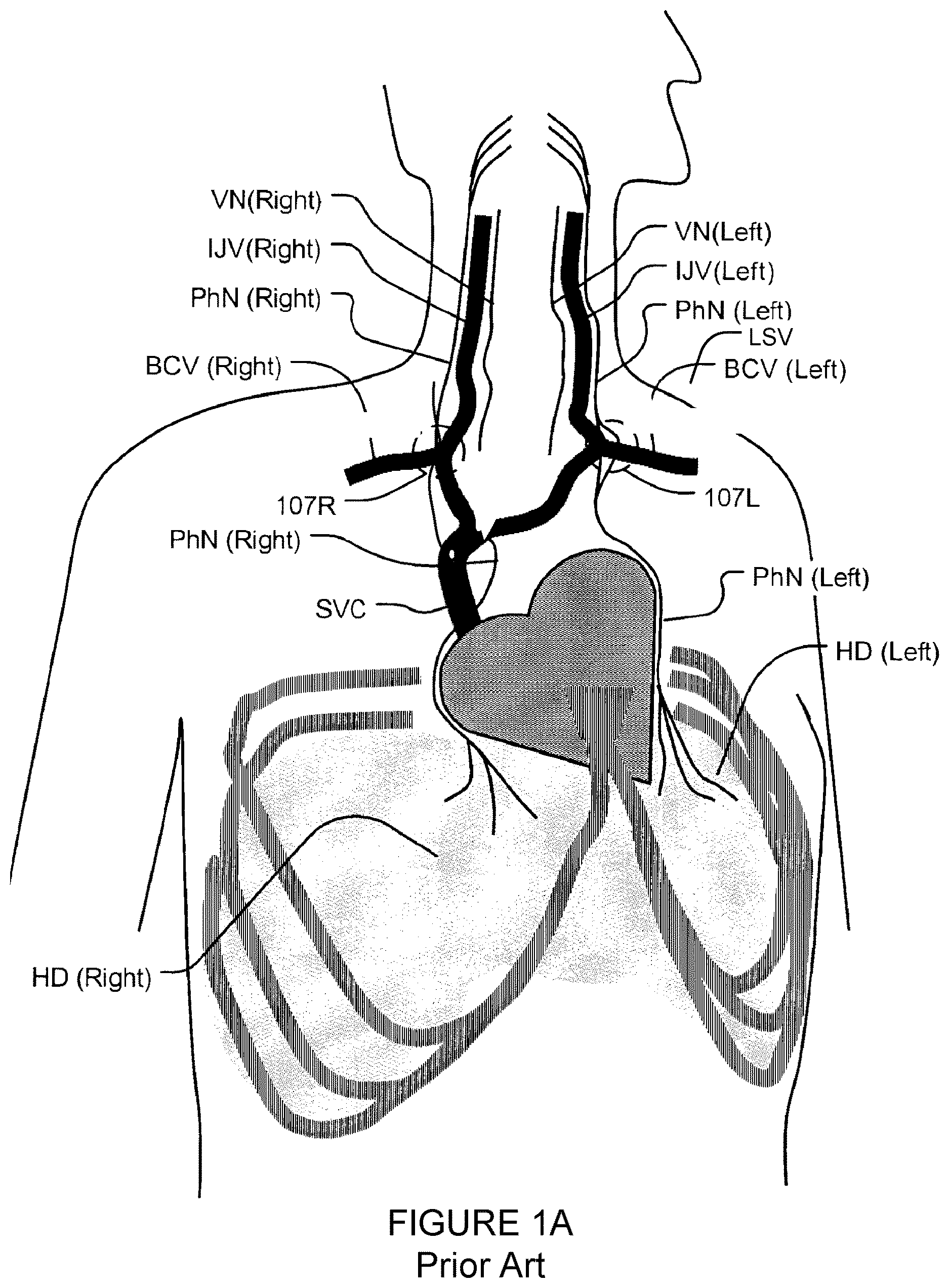
One aspect of the invention relates to transvascular stimulation of nerves in the neck and chest of a human or other mammals (e.g., a pig). A illustrates the anatomy of selected nerves and blood vessels in the neck and chest of a human and, in particular, the relative locations of the left and right phrenic nerves (PhN), vagus nerves (VN), internal jugular veins (IJV), brachiocephalic veins (BCV), superior vena cava (SVC) and left subclavian vein (LSV).
Further aspects of the invention and features of example embodiments are illustrated in the appended drawings and/or described in the text of this specification and/or described in the accompanying claims.
BRIEF DESCRIPTION OF THE DRAWINGS
The accompanying drawings illustrate non-limiting example embodiments of the invention.
A illustrates the anatomy of selected nerves and blood vessels in a person's neck and upper torso.
A- 2 D are schematic views of a nerve stimulation apparatus according to an example embodiment of the invention.
A- 3 C illustrate the operation of nerve stimulation apparatus.
A illustrates a shaft portion comprising a pair of attached tubes.
B illustrates a shaft portion comprising telescoping tubes.
A and 5 B are schematic views of a nerve stimulation apparatus according to an example embodiment of the invention.
A and 6 B are schematic views of a nerve stimulation apparatus according to another example embodiment of the invention.
A and 7 B are schematic views of a nerve stimulation apparatus according to another example embodiment of the invention.
schematically shows a nerve stimulation apparatus according to another example embodiment of the invention.
schematically shows a nerve stimulation apparatus according to another example embodiment of the invention.
A is a side view of a nerve stimulation apparatus according to another example embodiment of the invention. B is an isometric view of the apparatus of A in combination with an introducer and a hub. C and 10 D are examples of alternative cross-sectional views of the apparatus of A .
A and 11 B show a nerve stimulation apparatus in combination with an introducer and a hub according to an example embodiment of the invention. C and 11 D are cross sectional views of nerve stimulation apparatus along lines B-B and A-A respectively shown in B .
shows a nerve stimulation apparatus according to an example embodiment of the invention.
A shows a nerve stimulation apparatus according to an example embodiment of the invention that provides a five-lumen catheter. B- 13 E show some possible cross sections of the apparatus of A taken at line A-A in A .
A shows another embodiment of a nerve stimulation apparatus. B and 14 C show some possible cross sections of a tubular member of the apparatus of A .
shows a nerve stimulation apparatus.
shows a nerve stimulation apparatus.
shows a nerve stimulation apparatus.
A, 18 B show an electrode structure according to an example embodiment of the invention. A is a top plan view of the electrode structure. B is a bottom perspective view of the electrode structure.
A shows a schematic of a cross section of an electrode structure according to one example embodiment of the invention. B shows details electrodes of the electrode structure of A .
A and 20 B are perspective and side views of an electrode retaining wire according to one example embodiment.
A, 21 B are top and bottom perspective views of an electrode structure.
shows an electrode structure according to one example embodiment.
A- 23 E show how an example electrode structure may be rolled up and retracted into a tubular member.
A- 24 E show how an example electrode structure may be rolled up, deployed, and retracted into a tubular member.
show two example electrode structures.
A- 27 E schematically illustrate a nerve stimulation apparatus according to another embodiment.
A, 28 B show an example method for locating an electrode structure in a blood vessel V to stimulate a target nerve.
A- 29 H, 29 L- 29 Q, and 30 A- 30 H show various sensors which may be used with the nerve stimulation apparatus described herein as well as in other contexts.
A to 31 E shows an example shroud design which may be used with the nerve stimulation apparatus described herein as well as in other contexts.
DETAILED DESCRIPTION
Throughout the following description, specific details are set forth in order to provide a more thorough understanding of the invention. However, the invention may be practiced without these particulars. In other instances, well-known elements have not been shown or described in detail to avoid unnecessarily obscuring the invention. Accordingly, the specification and drawings are to be regarded in an illustrative, rather than restrictive.
Apparatus according to some embodiments provides intravascular electrode systems which include one or more electrodes supported on an elongated resiliently flexible support member. The support member may be used to introduce the electrodes into a blood vessel. As the support member is introduced into the blood vessel the support member bends to follow the path of the blood vessel. Restoring forces resulting from the resilience of the support member hold the one or more electrodes in place against the wall of the blood vessel. The electrode structure may comprise flexible electrically insulating pads that insulate electrodes from being in direct contact with blood in the main passage of the blood vessel.
In some embodiments the apparatus includes two or more electrodes at spaced-apart locations along the support member. Spacing between the electrodes may be selected to allow the electrodes to be located proximate to anatomical structures, for example nerves passing nearby the blood vessel. In an example embodiment, electrodes are spaced apart on a support structure and oriented so that an intravascular electrode system may be placed with electrodes located to stimulate a patient's left and right phrenic nerves. The electrodes may optionally have different circumferential orientations with respect to a longitudinal centerline of the support structure.
In some embodiments the support member is more flexible in one direction than in another. This can help to preserve a desired orientation of electrodes while the electrode system is being introduced into a blood vessel.
In some embodiments the electrode system comprises a catheter having one or more lumens. The catheter may provide the functionality of a central catheter of the type commonly used in intensive care units, for example. Such embodiments provide the advantage of electrodes that may be applied, for example, for stimulating nerves (e.g. for diaphragm pacing) and/or for monitoring electrical activity in the body of a patient in the same package as a central catheter that may be required in any event. In some embodiments, the catheter also serves as a support structure as described above.
Some embodiments comprise electrode structures comprising electrodes and asymmetrical electrically-insulating backing sheets. The backing sheets can electrically isolate the electrodes from blood in the lumen of a blood vessel, thereby allowing more efficient stimulation of extravascular structures such as nearby nerves. The asymmetrical arrangement of the backing sheet allows the backing sheet to be rolled into a compact configuration for insertion of the electrode structure into a blood vessel while providing a backing sheet that can provide electrical insulation for two or more electrodes. In some embodiments the backing sheet has a generally trapezoidal configuration. The backing sheet may be formed so that it tends to unroll from the rolled configuration. The backing sheet may be formed with a natural curvature similar to that of a wall of a blood vessel against which the backing sheet will be deployed. The backing sheet may be but need not be completely electrically insulating. Such a backing sheet can be advantageous as long as it provides a resistance to the flow of electricity substantially greater than the resistance that would be provided by blood in the blood vessel in the absence of the backing sheet. Such electrode structures may be applied in a wide range of intravascular applications.
Some embodiments provide electrode structures that include a retainer that holds a backing sheet in place. The retainer may comprise, for example, a formed piece of wire that extends through apertures in the backing sheet. In some embodiments the retainer comprises a pair of wire sections, which may be generally parallel, that are each woven through apertures in the backing sheet. Distal ends of the wire sections may be joined. The wire sections may be parts of a continuous wire. Distal ends of the wire sections may be bent back over the backing sheet. In some embodiments the retainer is electrically conductive and may be applied as one electrode, for example a reference electrode for electrical measurements and/or one of two or more electrodes for delivery of stimulation. The backing sheet may be rolled around the retainer for introduction into a blood vessel. Such electrode structures may be applied in a wide range of applications.
Some embodiments provide electrode structures in which a backing sheet for one or more electrodes is provided by a wall of an inflatable structure. The structure may be inflated to hold the electrodes against a wall of a blood vessel. The structure may, for example, be located on a side of a catheter or other support member. In some embodiments, inflation of the inflatable structure actuates a backing member carrying one or more electrodes to move toward engagement with a wall of a blood vessel.
Some embodiments provide intravascular electrode structures on which one or more electrodes is supported on a support member which include integrated position-measurement transducers for measuring a displacement of an electrode along a blood vessel into which the electrode is being inserted. The apparatus, including the position-measurement transducers may be intended to be disposable after a single use. Various embodiments of example position measurement transducers that can provide accurate position measurement in a suitable form factor and/or may be fabricated inexpensively are described below.
The following description describes examples of nerve stimulation apparatus and components suitable for application in nerve stimulation. In some cases the examples given are adapted for stimulation of phrenic nerves in a human or other mammals. The nerve stimulation apparatus described herein has a number of features which are particularly advantageous in combination with one another but can also be used individually, in other combinations, or in combination with the features described in US2010/0036451.
A- 2 C are schematics of a nerve stimulation apparatus 10 according to an example embodiment of the invention. Nerve stimulation apparatus 10 comprises electrode structures 12 A, 12 B (collectively 12 ). Nerve stimulation apparatus 10 also comprises a tubular member 24 . Tubular member 24 may be a catheter or cannula-type tubular member. For example, tubular member 24 may be a central venous catheter. Tubular member 24 is capable of being inserted into a lumen of a blood vessel.
Tubular member 24 has a distal end 26 , a proximal end 28 , an outer wall or sheath 30 that extends from distal end 26 to proximal end 28 . Tubular member 24 may comprise one or more internal lumens (not specifically indicated in A- 2 C —examples of such lumens are shown in other Figs.) For example, tubular member 24 may be a multi-lumen catheter.
In the example embodiment, at least one lumen extends longitudinally from proximal end 28 to distal end 26 . The lumens may have exit openings on wall 30 of tubular member 24 . These openings may be spaced apart along the length of tubular member 24 . The lumens may be used for removing blood samples, inserting medication, delivering fluids or nutrients, measuring chemical or physical parameters in blood, such as pH or temperature, and the like. For example, agents may be applied through one or more of the openings to prevent clot formation on electrode structures 12 . In A , an example opening 34 is shown, which provides an exit port for electrode structure 12 B. Opening 34 may be upstream from electrode structure 12 B relative to a direction of blood flow in a blood vessel in which nerve stimulation apparatus 10 is deployed.
Tubular member 24 may be flexible. A range of materials may be used for construction of tubular member 24 , including silicone, polyurethane, or other suitable polymers, stainless steel, and the like. Tubular member 24 may have markings for length determination. In some embodiments, tubular member 24 is more flexible in one bending direction than in another bending direction. In some embodiments, different sections of tubular member 24 have different levels of flexibility. For example, the distal part of tubular member 24 may be more flexible than the proximal part of tubular member 24 .
Electrode structure 12 A is positioned at or near distal end 26 of tubular member 24 . Electrode structure 12 B is positioned at a mid-portion of tubular member 24 . Electrode structures 12 A, 12 B are movable between a retracted position (i.e., received in tubular member 24 ) and a deployed position (i.e., extending out of tubular member 24 ). When electrode structures 12 A, 12 B are in a retracted position, electrode structures 12 A, 12 B are located inside or mostly inside tubular member 24 ( A ). When electrode structure 12 A, 12 B are in a deployed position, electrode structure 12 A extends out of a distal opening of tubular member 24 , and electrode structure 12 B extends out of tubular member 24 from an opening 34 on wall 30 ( B and 2 C ). Typically, electrode structure 12 is dimensioned so that, when in a deployed position inside a blood vessel, it will extend approximately 45° to 60° of the way around a wall of the blood vessel, although this is not mandatory.
In A- 2 C , a representative electrode 20 is shown for each electrode structure 12 . However, it should be noted that each electrode structure 12 may comprise a plurality of electrodes. For example, one or more electrodes may be used for stimulating a target nerve; and one or more additional electrodes may be used for ECG monitoring. In some embodiments, one electrode may function as a cathode and another electrode may function as an anode. Electrode structure 20 also comprises an insulating pad 42 .
Each electrode structure 12 may be coupled to an elongated flexible shaft portion 14 which extends inside tubular member 24 . Shaft portion 14 is not directly visible in A- 2 C , but D schematically shows a shaft portion 14 coupled to electrode 12 A, without tubular member 24 . In D , elongated flexible shaft portion 14 has a distal end 16 and a proximal end 18 . Electrode structure 12 A is coupled to distal end 16 of shaft portion 14 . Shaft portion 14 may comprise, for example, a single wire or tube or a plurality of wires or tubes. Shaft portion 14 may comprise one or more suitable leads (not specifically indicated in D , as leads may be hidden inside shaft portion 14 ) which may electrically couple one or more electrodes 20 to an apparatus for monitoring electrical activity and/or delivering electrical stimulation by way of electrodes 20 . The leads and the electrodes 20 may be electrically coupled in a one-to-one relationship such that each electrode 20 is individually addressable. In some embodiments, some groups of two or more electrodes 20 are connected to a common lead. The leads may be carried in or along shaft portion 14 .
At equilibrium, shaft portion 14 may have a configuration that is straight or curved. Shaft portion 14 may have an initial radius of curvature greater than a radius of curvature of the left brachiocephalic vein (BCV) and superior vena cava (SVC) into which nerve stimulation apparatus 10 may be introduced. Shaft portion 14 may be resilient and tending to return to its original configuration; thus, distal end 16 of shaft portion 14 tends to spring toward the far wall of the superior vena cava (SVC) when nerve stimulation apparatus 10 is inserted in a patient from the left side of the body (e.g., from LSV into BCV and SVC). This is convenient because the right phrenic nerve typically runs alongside the far wall of the superior vena cava (SVC) at this point.
In some embodiments, shaft portion 14 is more flexible in one direction than in another direction. For example, shaft portion 14 may be oriented such that it is easier to bend downwardly than sideways. This facilitates insertion and positioning of shaft portion 14 in SVC which extends downwardly from the BCV.
In some embodiments, different parts of shaft portion 14 have different levels of flexibility. For example, the distal part of shaft portion 14 may be more flexible than the proximal part of shaft portion 14 . In some embodiments, flexibility of the shaft portion may vary along the length of the shaft portion. Shaft portion 14 may be made of stainless steel or other suitable material (e.g., Nitinol, high-density plastics, elastomers etc.). In some embodiments shaft portion 14 comprises a pair of flexible stainless steel tubes that are attached together by, for example, welding.
The operation of nerve stimulation apparatus 10 is schematically shown in A- 3 C . Nerve stimulation apparatus 10 may be inserted into a person's subclavian vein and SVC as follows. The electrode structures 12 A, 12 B are initially located within tubular member 24 . A percutaneous puncture is made into the patient's LSV. Tubular member 24 is then inserted through the puncture into the LSV. Such insertion could be done under local anaesthesia. General anaesthesia is typically not required. Tubular member 24 of nerve stimulation apparatus 10 is then advanced into the patient's left BCV and eventually into SVC. Care should be taken not to advance tubular member 24 into the right atrium of the heart. When the distal portion of tubular member 24 reaches the SVC, the distal portion of tubular member 24 bends downwardly. Electrode structures 12 A, 12 B are moved from a retracted position ( B ) to a deployed position ( C ). Electrode structures 12 A, 12 B are positioned adjacent the left and right phrenic nerves. As described below, monitoring may be performed during insertion to locate the electrode positions which allow for most effective stimulation of the phrenic nerve.
In the deployed position, electrode structures 12 A, 12 B extend out of tubular member 24 . Electrodes 20 are pressed against a wall of the blood vessel, whereas the insulating pads 42 of the electrode structures 12 A, 12 B prevent the electrodes 20 from being in close electrical contact with the bulk of the blood flowing through the blood vessel. The curvature of nerve stimulation apparatus 10 may conform to the curvature of the patient's left BCV and SVC. The two electrode structures 12 A, 12 B may be arranged roughly at 90° to one another about the longitudinal axis of nerve stimulation apparatus 10 , with electrode structure 12 A oriented toward the right phrenic nerve and electrode structure 12 B oriented toward the left phrenic nerve.
Testing may be done to locate electrode structures 12 A, 12 B at desired positions relative to the left and right phrenic nerve. Methods for locating an electrode structure relative to a target nerve are described below herein (see A, 28 B ). Measurements can also be made to determine which electrode or electrodes of an electrode structure comprising multiple electrodes most effectively stimulate the target nerve.
Once nerve stimulation apparatus 10 has been properly inserted into a patient as described above, electrodes 20 are electrically coupled to a stimulation device (e.g., a pulse generator which may be optionally located outside the body) to apply electric current to the phrenic nerves, causing the diaphragm muscle to contract. The contraction of the diaphragm muscle causes inhalation of air into the lungs. When the electric stimulation of the phrenic nerves is stopped, the diaphragm muscle relaxes and exhalation occurs. This allows the patient to breathe more naturally. Nerve stimulation apparatus 10 may be used in combination with a control unit (e.g., a bedside control unit).
Nerve stimulation apparatus 10 may be removed from the patient's body. During removal, electrode structures 12 A, 12 B may be first moved from a deployed configuration ( C ) to a retracted configuration ( B ). Once the electrode structures 12 A, 12 B are retrieved into tubular member 24 , the entire nerve stimulation apparatus 10 may be withdrawn from the patient's body. Alternatively, removing may not require retraction of electrode structure into the tubular member. Preferred methods for retrieving nerve stimulation apparatus 10 from the patient's body have a number of advantages which include one or more of: (1) nerve stimulation apparatus 10 can be repositioned easily for replacement or if the electrode moves with respect to target nerves, for example while the patient is being moved or transferred; (2) periodic removal of nerve stimulation apparatus prevents the build-up of plaques, or inflammation, or other undesirable physiological or pathological consequences as a result of implanting nerve stimulation apparatus in a blood vessel; (3) nerve stimulation apparatus 10 can be conveniently removed from the patient when nerve stimulation treatment is no longer needed.
Shaft portion 14 may take a number of different configurations. In the embodiment shown in A , a shaft portion 14 A comprises a pair of tubes 14 A 1 , 14 A 2 that are joined together in parallel. Tubes 14 A 1 , 14 A 2 may be welded or affixed in another suitable manner together at certain spaced apart points or continuously along their length. Tubes 14 A 1 , 14 A 2 may be made of stainless steel or other suitable material. The two-tube configuration in A allows shaft portion 14 A to bend more easily in a plane extending between the two tubes than in a plane of the two tubes.
In the embodiment shown in B , a shaft portion 14 B comprises a pair of tubes 14 B 1 , 14 B 2 that are coupled together in a concentric fashion. Tube 14 B 1 has a smaller diameter than tube 14 B 2 and is insertable and movable in tube 14 B 2 . Tube 14 B 1 is distal to tube 14 B 2 . Tube 14 B 1 may be more flexible than tube 14 B 2 .
A and 5 B are schematic views of a nerve stimulation apparatus 10 C according to an example embodiment of the invention (in a deployed configuration and a retracted configuration respectively). In the A and 5 B embodiment, electrode structure 12 AC is coupled to a distal end of shaft portion 14 C, and electrode structure 12 BC is coupled to a mid-portion of shaft portion 14 C. The coupling between electrode structure 12 B and shaft portion 14 C may comprise a spring mechanism 35 C. Electrode structure 12 AC is retractable and extendable through a distal opening of tubular member 24 C. Electrode structure 12 BC is retractable and extendable through a side opening 34 C of tubular member 24 C.
A and 6 B are schematic views of a nerve stimulation apparatus 10 D according to another example embodiment of the invention. In the embodiment shown in A and 6 B , nerve stimulation apparatus 10 D comprises a first tubular member 24 D and a second tubular member 36 D. Electrode structure 12 AD is coupled to a distal end of shaft portion 14 D. However, electrode structure 12 BD is disposed on first tubular member 24 D. Also, first tubular member 24 D passes through second tubular member 36 D and electrode structure 12 BD is retractable into second tubular member 36 D. First and second tubular members 24 D, 36 D may be assembled in a telescoping fashion. Second tubular member 36 D has a diameter greater than the diameter of first tubular member 24 D. Second tubular member 36 D is typically shorter than first tubular member 24 D. The position of electrode structures 12 AD, 12 BD may be controlled independently from one another via shaft portion 14 D and tubular member 24 D respectively.
A and 7 B are schematic views of a nerve stimulation apparatus 10 E according to another example embodiment of the invention. In the A and 7 B embodiment, electrode structure 12 AE is coupled to a shaft portion 14 E 1 , and electrode structure 12 BE is disposed on a shaft portion 14 E 2 which is separate from shaft portion 14 E 1 . Shaft portion 14 E 2 may be structurally different from shaft portion 14 E 1 . Shaft portions 14 E 1 , 14 E 2 may be independently controlled to deploy or retract electrode structures 12 AE, 12 BE, respectively. Also, first tubular member 24 E passes through a second tubular member 36 E. Electrode structure 12 AE is retractable into first tubular member 24 E. Electrode structure 12 BE is retractable into second tubular member 36 E. Second tubular member 36 E has a diameter greater than the diameter of first tubular member 24 E. Second tubular member 36 E is typically shorter than first tubular member 24 E.
schematically shows a nerve stimulation apparatus 10 F according to another example embodiment of the invention. In the embodiment, electrode structure 12 AF is coupled to a shaft portion 14 F 1 , and electrode structure 12 BF is disposed on a shaft portion 14 F 2 which is separate from shaft portion 14 F 1 . Shaft portion 14 F 2 may be structurally different from shaft portion 14 F 1 . Shaft portions 14 F 1 , 14 F 2 may be independently controlled to deploy or retract electrode structures 12 AF, 12 BF, respectively. Tubular member 24 F comprises a single lumen 32 F. Both shaft portions 14 F 1 and 14 F 2 extend inside lumen 32 F. Electrode structure 12 AF may extend out of a distal opening of lumen 32 F. Electrode structure 12 BF may extend out of a side opening 34 F of tubular member 24 F.
schematically shows a nerve stimulation apparatus 10 G according to another example embodiment of the invention. Apparatus 10 G is similar to apparatus 10 F except that tubular member 24 G of apparatus 10 G comprises two lumens 32 G 1 and 32 G 2 . The two lumens 32 G 1 and 32 G 2 are separated by a partition 33 G. Shaft portion 14 G 1 extends in lumen 32 G 1 and electrode structure 12 AG extends out of a distal opening of lumen 32 G 1 . Shaft portion 14 G 2 extends in lumen 32 G 2 and electrode structure 12 BG extends out of a side opening 34 G of lumen 32 G 2 .
A is a side view of a nerve stimulation apparatus 10 H according to an example embodiment of the invention. B is an isometric view of apparatus 10 H in combination with an introducer 38 H and a hub 40 H. C, 10 D are possible cross-sectional views of apparatus 10 H. Nerve stimulation apparatus 10 H comprises electrode structures 12 AH, 12 BH, and a tubular member 24 H.
Nerve stimulation apparatus 10 H may be coupled to an introducer 38 H and a hub 40 H. This may be done during use to facilitate entry of the nerve stimulation apparatus into a patient's blood vessel. It should be noted that other types of introducers and/or hubs different from the ones shown in B may also be used in conjunction with nerve stimulation apparatus 10 H. Electrode structure 12 AH is connected to a shaft portion 14 H which extends inside tubular member 24 H. Electrode structure 12 BH is disposed on first tubular member 24 H. The distance between electrode structure 12 AH and 12 BH may be in the range of 5-10 cm for example. The distance between electrode structure 12 BH and the distal end of introducer 38 H may be in the range of 0-5 cm for example.
Tubular member 24 H is partially received in tubular member 36 H of introducer 38 H. When nerve stimulation apparatus 10 H is applied to a patient, hub 40 H and the wing portion of introducer 38 H stay outside of the patient. Introducer 38 H and/or hub 40 H may comprise holes for suture. In their deployed configuration, electrode structures 12 AH and 12 BH have a transverse dimension that is greater than the transverse dimension of tubular member 24 H. Apparatus 10 H comprises a thermistor 64 H or other temperature sensor.
Tubular member 24 H may comprise a multi-lumen catheter. C, 10 D show possible cross sections of tubular member 24 H. Tubular member 24 H may have 1, 2, 3, 4, 5, or more lumens 32 H. Shaft portion 14 H and leads 45 H may run inside one or more of the lumens 32 H. Leads 45 H may also run inside the bore of shaft portion 14 H.
A and 11 B show a nerve stimulation apparatus 10 I in combination with an introducer 38 I and a hub 40 I according to an example embodiment of the invention. C and 11 D are cross sectional views of nerve stimulation apparatus 10 along lines B-B and A-A respectively in B . Nerve stimulation apparatus 10 I comprises a first tubular member 24 I, a second tubular member 36 I, an introducer 38 I, a hub 40 I, a first electrode structure 12 AI, a second electrode structure 12 BI, a first shaft portion 14 I (not visible) and a second shaft portion 68 I (not visible). Electrode structure 12 AI is attached to a distal end of first shaft portion 14 I. First shaft portion 14 I is visible in C and 11 D (in cross section). Electrode structure 12 AI is retractable into the distal end of tubular member 24 I. Electrode structure 12 BI is attached to second shaft portion 68 I. Electrode structure 12 BI is extendable out of the distal end of second tubular member 36 I and is retractable into the distal end of tubular member 36 I. Second shaft portion 68 I is visible in C (in cross section). First tubular member 24 I is longer than second tubular member 36 I and passes through second tubular member 36 I. First tubular member 24 I comprises a plurality of lumens 32 I, and second tubular member 36 I surrounds the multi-lumen first tubular member 24 I. Because electrode 12 AI and 12 BI are attached to two separate shaft portions 14 I and 68 I, respectively, electrode structures 12 AI and 12 BI can be independently controlled from outside the body.
shows a nerve stimulation apparatus 10 J according to an example embodiment of the invention. Apparatus 10 J comprises a tubular member 24 J. Electrode structure 12 AJ extends out of the distal end of tubular member 24 J whereas electrode 12 BJ extends out of an opening 34 J on tubular member 24 J. Electrode structure 12 AJ is attached to shaft portion 14 J and electrode structure 12 B is attached to shaft portion 68 J. Shaft portions 14 J and 68 J are both inside tubular member 24 J. Electrode structures 12 AJ and 12 BJ can be independently controlled from outside the body.
A shows a nerve stimulation apparatus 10 K. In this embodiment, tubular member 24 K has five lumens 32 K. B- 13 E show some possible cross sections of tubular member 24 K taken at line A-A in A . Three lumens 32 K may be used for drug infusion and are in fluid communication with openings 62 AK, 62 BK, 62 CK located in a proximal, middle and distal portion of tubular member 24 K. One lumen contains shaft portion 14 K which is coupled to electrode structure 12 AK. One lumen contains shaft portion 68 K which is coupled to electrode structure 12 BK. In B , each of the five lumens has the same size and has a circular cross section. In C , the lumens have different sizes, but all have circular cross sections. In D , the lumens have different sizes and non-circular cross sections. In E , the lumens have different sizes and are a mix of circular and non-circular cross sections.
A is another embodiment of a nerve stimulation apparatus 10 L. B and 14 C show some possible cross sections of tubular member 24 L in the A embodiment. In the A embodiment, tubular member 24 L has three lumens 32 L. One lumen 32 L contains shaft portion 14 L which is coupled to electrode structure 12 AL. One lumen 32 L contains shaft portion 68 L which is coupled to electrode structure 12 BL. One lumens may be used for drug infusion to opening 62 L located in a middle portion of tubular member 24 L. In B , each of the three lumens has the same size and has a circular cross section. In C , the lumens have non-circular cross sections.
shows a nerve stimulation apparatus 10 M. Apparatus 10 M comprise a tubular member 24 M. The proximal end of tubular member 24 M is coupled to introducer 38 M. Introducer 38 M has a side port 39 M. Both electrode structures 12 AM, 12 BM extend out of a distal opening of tubular member 24 M. Electrode structure 12 AM is coupled to shaft portion 14 M. Electrode structure 12 BM is coupled to shaft portion 68 M. Electrode structures 12 AM and 12 BM can be independently controlled.
shows a nerve stimulation apparatus 10 N. Nerve stimulation apparatus 10 N comprises a tubular member 36 N, an electrode structure 12 N and a shaft portion 14 N (not visible). Electrode structure 12 N extends out of a distal opening of tubular member 36 N. Shaft portion 14 N is inside tubular member 36 N. Tubular member 36 N may be a cannula or catheter-type tubular member. The length of tubular member 36 N is sufficiently long to enter the vessel by about 1 cm such that nerve stimulation apparatus 10 N is suitable for stimulating the left phrenic nerve when inserted into a patient's LSV and left BCV.
shows a nerve stimulation apparatus 10 O. Nerve stimulation apparatus 10 O comprises a tubular member 24 O, an electrode structure 12 O and a shaft portion 14 O (not visible). Electrode structure 12 O is attached to a distal end of shaft portion 14 O. Shaft portion 14 O is not visible in because shaft portion 14 O is inside tubular member 24 O. Tubular member 24 O may be a catheter-type tubular member. The length of tubular member 24 O may be 16-20 cm so that nerve stimulation apparatus 10 O is suitable for stimulating the right phrenic nerve when inserted into a patient's LSV, left BCV and then enters SVC. It should be noted that apparatus 10 N, 10 O may be used in combination to stimulate both left and right phrenic nerves at the same time.
A, 18 B show an electrode structure 12 P according to an example embodiment of the invention. A is a top plan view of electrode structure 12 P. B is a bottom perspective view of electrode structure 12 P. Electrode structure 12 P comprises at least one electrode 20 P and an insulating pad 42 P. Pad 42 P may be resiliently flexible. When electrode structure 12 P is not confined inside a tubular member, pad 42 P can automatically spring open to take a desired shape. When electrode structure 12 P springs open, electrode structure 12 P may have a dimension that is greater than the transverse dimension of the tubular member. To retrieve electrode structure 12 P into a tubular member, electrode structure 12 P can be collapsed and/or pulled back into the tubular member by pulling shaft portion 14 P which is coupled to electrode structure 12 P. Electrode 20 P may be supported on pad 42 P, but this is not mandatory. Pad 42 P has a petal or leaf-like shape, although pad 42 P may be of any other suitable shape. Pad 42 P may be an insulating pad, thereby insulating electrode 20 P from the blood in a blood vessel. Pad 42 P may be made of an insulating material or materials. Suitable materials for making pad 42 P include, without limitation, PTEF, silicone, PET, and nylon. Pad 42 P may present a high-impedance to the flow of electrical current and therefore reduces the amount of current flowing through the blood when electrode structure 12 P is deployed in a blood vessel.
It is not mandatory that pad 42 P have an extremely high electrical resistance. It is sufficient if pad 42 P has a resistance to the flow of electricity through pad 42 P that is significantly greater than that presented by the blood in blood vessel V. Blood typically has a resistivity of about 120 to 190 Ωcm. In example embodiments, the blood in a blood vessel may provide an electrical resistance between closely-spaced electrical contacts that is inversely proportional to the dimensions of the lumen of the blood vessel. In large blood vessels the longitudinal electrical resistance between reasonable closely-spaced contacts can be a few tens of ohms for example. Pad 42 P preferably provides an electrical resistance of at least a few hundred ohms, preferably a few kilo ohms or more to the flow of electrical current through the thickness of pad 42 P. Pad 42 P could have electrically conductive members such as leads and the like embedded within it or electrically-conductive electrode or other features on its inner surface and still be considered to be ‘insulating’.
For example, electrode 20 P may be supported on pad 42 P. Pad 42 P can be rolled up and retracted into the tubular member to facilitate insertion or retrieval of electrode structure 12 P within a blood vessel. When electrode structure 12 P is deployed, pad 42 P can spring open to take a shape that has a curvature that generally conforms to the wall of a blood vessel. This helps to bring electrode 20 P which is on a side of pad 42 P to be in close proximity of the blood vessel wall. Blood flow in the blood vessel may also assist in deploying electrode structure 12 P and pressing pad 42 P against the walls of a blood vessel. It should be noted that electrode structure 20 P does not need to be fixed or fastened to the blood vessel wall, but rather can float inside the blood vessel against the wall.
In the embodiment of A, 18 B , electrode structure 12 P also comprises a wire 44 P which is connected to shaft portion 14 P. Wire 44 P passes through apertures 46 P in pad 42 P, thereby holding pad 42 P in place. Wire 44 P may provide structural support to pad 42 P. Additionally, wire 44 P may optionally serve as a ground electrode or a reference electrode. In B , a lead 45 P extends from a bore in shaft portion 14 P to a backside 56 P of electrode 20 P. Lead 45 P may be coated with an insulating material (e.g., Teflon™ or other suitable insulating material). Sensors such as a thermistor, an oxygen sensor, and/or CO 2 sensor (not shown) may be supported on electrode structure 12 P. In some embodiments, electrode structures 12 P may be used for plethysmography.
In the illustrated embodiment, electrode 20 P is exposed on one side (e.g., the convex side, i.e., the side facing the blood vessel wall) of pad 42 P. Pad 42 P may, for example, comprise a reinforced silicone material. In one embodiment, pad 42 P is a pad of Dacron-mesh-reinforced silicone. This material can be rolled up, has shape memory so that it tends to open up, and is resiliently flexible so that it can conform to the wall of a blood vessel. Blood flow in the blood vessel may also assist in deploying electrode structure 12 P and supporting electrode structure 12 P against the walls of a blood vessel.
A shows a schematic of a cross section of an electrode structure 12 Q according to one example embodiment of the invention. In A embodiment, electrode 20 Q comprises one or more ribbons 48 Q of a suitable biocompatible metal. Pad 42 Q on which the ribbons 48 Q are supported comprises two layers. A top layer 50 Q which faces the wall of the blood vessel has apertures 52 Q and the ribbons 48 Q pass through aperture 52 Q such that a portion of the ribbons 48 Q is exposed and able to contact or be in close proximity of a wall 54 Q of the blood vessel. This is schematically shown in B . The bottom layer 56 Q which faces the center of the blood vessel may be made of a suitable insulating material. Ribbons 48 Q are electrically coupled to lead 45 Q which is directly or indirectly coupled to a source of electricity (e.g., a stimulation generator). The bottom insulating layer 56 Q may comprise a thin material such as Teflon™, polyurethane, or silicone.
The material of electrode 20 Q is preferably relatively thin so that it does not make the electrode structure too stiff. For example, the electrode material may comprise metal ribbons 48 Q that are 0.5 to 1 mm wide, or less than 0.5 mm wide. In other embodiments the electrodes may comprise areas of conductive polymer printed on or contained in the insulating material of the electrode structure.
Generally, the delivery of electrical stimulation to a target nerve is enhanced by:
•
• locating electrode 20 against the internal wall of the blood vessel at a location close to the target nerve; • providing electrode 20 having a relatively large contact surface that can achieve a large contact area with the internal wall of the blood vessel; • curving the contact surface of electrode 20 to roughly match the curvature of the inner face of blood vessel; and/or • providing insulating pad 42 .
Experiments conducted by the inventors have shown that it is possible to achieve a similar level of stimulation of a target nerve using insulated electrodes by applying only one third of the electric current as compared to using uninsulated electrodes. The reduced electric current can result in less damage to tissues within a patient as well as a lower risk of unintended stimulation. Additionally, selectivity for a target nerve is improved. Low current and high selectivity for a target nerve is advantageous because it avoids activating non-target nerves which may be close by. For example, it is known that the vagus nerve is typically 2-3 cm medial with respect to the phrenic nerves in humans.
A and 20 B are perspective and side views of wire 44 P according to one example embodiment. Wire 44 P is connected to shaft portion 14 P. Wire 44 P may form a hair-pin configuration, extending from shaft portion 14 P on one side of pad 42 P (not shown in A and 20 B ), passing through apertures 46 P in pad 42 P to the other side of pad 42 P and then extending in the opposite direction.
Where shaft portion 14 P comprises stainless steel tube(s), the wire 44 P may, for example, be welded or otherwise attached to the stainless steel tube(s). Wire 44 P may comprise a loop of 0.010 inch stainless steel (for example Elgiloy™). The wire of the loop may pass through apertures 46 P in the insulating pad 42 P on which electrode(s) 20 P are supported as shown in A, 18 B . This positively retains pad 42 P in place. Wire 44 P may be passed through apertures 46 P before being affixed to shaft portion 14 P. In some embodiments, wire 44 P provides one of a plurality of electrodes for monitoring bioelectrical activity and/or delivering electrical stimulation.
A, 21 B are top and bottom perspective views of an electrode structure 12 R. Electrode structure 12 R is similar to electrode structure 12 P. In A, 21 B , pad 42 R is flexible and partially rolled-up, and electrode 20 R is located on the convex side of pad 42 R.
shows an electrode structure 12 S according to one example embodiment. As shown in , pad 42 S of electrode structure 12 S is asymmetrical. This provides better coverage and provides the possibility of placing the electrodes 20 S at more discrete locations around a blood vessel while still being able to compactly roll up the electrode structure 12 S for insertion and retrieval. A plurality of electrodes 20 S are provided on electrode structure 12 S. Providing a plurality of electrodes 20 S on each electrode structure allows selection of an electrode or a combination of electrodes to provide the most effective stimulation of a target nerve.
A- 23 E show how an example electrode structure 12 T may be rolled up and retracted into a tubular member 24 T. In A-E , pad 42 T of electrode structure 12 T is flexible enough that electrode structure 12 T can be pulled into tubular member 24 T by pulling shaft portion 14 T (not visible) which is coupled to electrode structure 12 T.
A- 24 E show how an example electrode structure 12 U may be rolled up, deployed, and retracted into a tubular member 24 U. As shown in A , electrode structure 12 U may initially be fully rolled up inside tubular member 24 U (e.g., when nerve stimulation apparatus 10 is being inserted into a patient's blood vessel). The two halves of pad 42 U of electrode structure 12 U may be rolled up in the same direction.
As shown in B and 24 C , when nerve stimulation apparatus 10 is located in a desired position in the patient's blood vessel, electrode structure 12 U may be deployed by moving electrode structure 12 U out of tubular member 24 U and opening pad 42 U. As shown in D and 24 E , electrode structure 12 U may be retrieved by turning or rotating shaft portion 14 U from outside the body to roll up pad 42 U. Once pad 42 U is rolled up, electrode structure 12 U can be retrieved into tubular member 24 U. The entire tubular member 24 U which contains electrode structure 12 U can then be withdrawn from the patient's body.
show two example electrode structures 12 V, 12 W. The electrode structure 12 V has a pad 42 V that has a gentle curl (in cross section). Electrodes 20 V are located on a convex side of pad 42 V. Pad 42 V comprises a low-stiffness spring wire loop 70 V. In , wire loop 70 V is in its relaxed, expanded configuration. Wire loop 70 V may be made of nitinol or stainless steel, for example. Wire loop 70 V may be located on the side of pad 42 V that is facing the center of the blood vessel (e.g., the concave side of pad 42 V) and opposite from the side where electrodes 20 V are located. Alternatively, wire loop 70 V may be sandwiched inside a pocket formed by two insulating pad layers of pad 42 V. Electrodes 20 V are exposed on the side of pad 42 V that is facing the wall of the blood vessel (e.g., the convex side of pad 42 V). Wire 44 V is woven and adhered to pad 42 V to provide structural support and stiffness to pad 42 V. Electrode structure 12 V may be withdrawn into tubular member 24 V by pulling on shaft portion 14 V from outside the body. On reaching the edge of tubular member 24 V, the low stiffness deformable spring wire loop 70 V collapses and pad 42 V enters tubular member 24 V. The tubular member 24 V together with electrode structure 12 V is then withdrawn from the body.
The electrode structure 12 W is similar to the electrode structure 12 V except that wire loop 70 V is replaced with deformable low-stiffness springy ribs 72 W. Electrode structure 12 W may be retrieved into tubular member 24 in a similar fashion as electrode structure 12 V.
A- 27 E schematically illustrate a nerve stimulation apparatus 10 X according to another embodiment. A shows apparatus 10 X coupled to a hub 40 X. B shows apparatus 10 X in position inside left BCV and SVC. Apparatus 10 X comprises electrode structures 12 AX, 12 BX (collectively 12 X). Electrode structures 12 AX, 12 BX may be the same or can be of different sizes and/or shapes. As shown in C , pad 42 X of each electrode structure 12 X comprises an inflatable balloon 58 X. The inflatable balloon 58 X may be made of a suitable polymer material (e.g., PET, nylon, silicone). The balloon 58 X may be compliant, semi-compliant, or non-compliant. The balloon 58 X may be inflated with a fluid (e.g, saline solution) and, once inflated, will take the desired shape. Electrodes 20 X are disposed on one side of pad 42 X. Electrodes 20 X may be printed or glued on balloon 58 X. Apparatus 10 X also comprises a conduit for infusing fluid into balloon 58 X, and the infusion of fluid into balloon 58 X can be controlled from outside the body. D shows electrode structure 12 X with balloon 58 X in a deflated state. E shows electrode structure 12 X with balloon 58 X in a inflated state. Out of the package, balloon 58 X is pleated and folded to wrap around shaft portion 14 X. Balloon 58 X is parked inside one of the lumens of apparatus 10 X. To deploy electrode structure 12 X, shaft portion 14 X is pushed from the proximal end of apparatus 10 X; balloon 58 X pops out of an opening of tubular member 24 X and then is inflated. To retrieve balloon 58 X, balloon 58 X is first deflated and then pulled into one of the lumens of apparatus 10 X from the proximal end of apparatus 10 X via shaft portion 14 X.
A, 28 B show an example method for locating electrode structure 12 in a blood vessel V to a target nerve N. In this method, electrode structure 12 is inserted into blood vessel V while electrode structure 12 is retracted within tubular member 24 . Electrode structure 12 is then extended out of tubular member 24 and positioned at location A. At this point, the amount of electric current required to stimulate nerve N is measured using a suitable device. This may be done, for example, by detecting muscle activity as a result of nerve stimulation, for example, diaphragm muscle activity as result of phrenic nerve stimulation. Electrode structure 12 is then retracted into tubular member 24 . Then tubular member 24 is advanced in blood vessel V for a small distance (e.g., 0.1 mm, 0.2 mm, 0.5 mm, 1 mm, 2 mm, 5 mm, etc.) and electrode structure 12 is then extended out of tubular member 24 and positioned at Location B. Again, the amount of electric current required to stimulate nerve N is measured using a suitable device. These steps are repeated (e.g. at Location C, Location D, Location E) for as many times as necessary.
By making a set of such measurements, one can obtain a function indicating how the amount of electric current required to stimulate nerve N varies in relation to the position of electrode structure 12 along blood vessel V. B shows a schematic graph of such a function. In this graph, the amount of electric current required to stimulate nerve N is the lowest at Location C. Therefore, in this illustration, Location C is a desirable or optimal location to place electrode structure 12 as compared to Locations A, B, D and E. This method can be practised either manually or in conjunction with a suitable machine, such as a graphing calculator or a computer.
One aspect of the invention relates to sensors for sensing and/or monitoring the position of an electrode structure 12 inserted into a blood vessel and associated methods. The sensor may be optionally disposable. The sensor may be placed outside of the patient's body. The sensor may be fixed to the reference frame of the patient's body. As an electrode structure 12 is advanced and/or rotated in a blood vessel by a therapist, the sensor acquires positional data and can also relay data to a control unit where electrode position is monitored simultaneously with stimulation parameters and results of stimulation. The control unit calculates the best placement of electrodes 20 and can store this information or provide feedback to the therapist in real time or at later times.
A nerve stimulation system according to an embodiment of the present invention may comprise the following: an intravascular nerve stimulation apparatus having flexible tubular member(s) that can be inserted, advanced, and/or rotated in a blood vessel; one or more sensors that track the position of the intravascular electrodes; and a control unit that acquires position data and relays it to the therapist and/or stores it for later use. Typically, the sensor is coupled to a proximal part of a shaft portion of the nerve stimulation apparatus. The sensor may be placed outside of the body.
A schematically shows an example embodiment of a sensor 80 A that is independent from an introducer or tubular member of an intravascular nerve stimulation apparatus 10 . B schematically shows an example embodiment of a sensor 80 B that is integrated with an introducer or tubular member of an intravascular nerve stimulation apparatus 10 .
In some embodiments, the sensor is a pressure-sensitive variable resistance potentiometer sensor. Such a sensor is suitable for monitoring the position (depth) of an intravascular electrode inside a blood vessel. The sensor supplies a voltage output signal that is approximately linearly proportional to the position of the electrode. C and 29 D show an example sensor 80 C in cross-sectional and perspective views. Sensor 80 C comprises a pressure-sensitive linear potentiometer 81 . A low-friction bead 82 C (e.g., a Teflon bead) is fixed onto an elongate shaft portion 14 . Potentiometer 81 , bead 82 , and part of shaft portion 14 are assembled within a guide chamber 84 C to form sensor 80 C. Sensor 80 C may be fixed either to the patient, or to the tubular member or the introducer of a nerve stimulation apparatus. As the shaft portion 14 advances, the bead 82 slides along and exerts pressure on potentiometer 81 , therefore changing its resistance. The point of contact of the bead 82 against the potentiometer 81 provides a signal that, provided that the shaft portion 14 does not buckle, is generally linearly proportional to the intravascular position of the electrode 20 .
The length of the active region of the potentiometer 81 limits the distance over which the depth of the electrode 20 can be tracked. In some embodiments, a commercially available flexible potentiometer may be used with a 6 cm long active region which is sufficient to monitor the movement of an electrode in the vicinity of its target phrenic nerve. However, potentiometers of any desired length may be manufactured for this purpose. If shaft portion 14 has a circular cross-section and bead 82 is spherical and coaxial the shaft portion 14 , the shaft portion 14 can be rotated while maintaining contact with the potentiometer 81 to obtain the angular positions of the shaft portion 14 and electrode 20 . F-H show an additional example embodiments of sensor 80 D, wherein the guide chamber 84 D has a generally triangular cross-section.
In some embodiments, sensor 80 is integrated with the hub of a nerve stimulation apparatus. An example sensors 80 G is shown in L . The depth and the angular position of an intravascular electrode can be monitored by combining the use of a linear potentiometer as described above, plus a circular potentiometer to monitor rotation of the shaft portion. Alternatively, the angular position can be controlled by a series of “click stops” placed at convenient angles (e.g., one stop every 15° or 30°) over a desired angular range (e.g., +/−90° from a central default angular position of an electrode) and a multi-pole electrical switch can be connected to indicate each click stop. To monitor rotation of the shaft portion, the shaft portion proximal to the linear transducer can be modified to be of non-circular cross-section, for example square cross-section, and a dial can be incorporated with a square hole through which the shaft portion travels. The therapist can manually rotate either the shaft portion itself or its associated dial, and the rotational movement of the dial is sensed by an integrated sensor housed inside the hub of the nerve stimulation apparatus or alternatively by a multi-pole electrical switch with pre-set click stops. L shows an embodiment wherein the shaft portions 14 can be rotated by dials.
M shows an embodiment of a sensor 80 H in which the shaft portion 14 is coupled by way of a string or other flexible element to a spring-loaded shaft fitted with a rotational sensor 90 . The rotational sensor's rotational axis 91 is fitted with a rotational encoder (not shown in M ), which can be converted into a linear displacement measurement. The shaft portion 14 is attached to rotational sensor 90 using a collar 92 and a wire 94 . As the shaft portion 14 is moved, the collar 92 slides through a guide 96 which prevents the shaft portion 14 from moving in any axis other than the one in which the rotational sensor 90 keeps track of position. To make the assembly smaller, rotational sensor 90 may be put at an angle by having the wire 94 redirected by a pulley or a block 98 . To move the shaft portion 14 , the collar 92 can be fitted with a slider or the assembly can allow the user to move the shaft portion 14 directly.
N and 29 O are side and front views of a sensor 80 J where the shaft portion 14 is fitted between a roller 100 and a guide 102 . As the shaft portion 14 passes the roller 100 , it creates a rotational motion of the roller 100 in the same direction. The rotational movement of the roller 100 is then converted to a linear movement through an encoder 104 . Both roller 102 and encoder 104 are located co-axially on a rotational axis 106 .
P shows a sensor 80 K wherein shaft portion 14 is fitted with a collar 108 made out of an insulating material. The collar 108 has at least one conductive ring 110 . Ring 110 slides through a guide 112 fitted with electrical contacts 114 . As the collar 108 slides through the guide 112 and the ring 110 touches the electrical contacts 114 on each side, a current passes through the ring 110 . The current may be converted to positional data, either by correlating position to resistance or by identifying the shorted contacts and associating them with a calibrated position.
Q shows a sensor 80 L in which a shaft portion 14 is fitted with two resistive traces 116 connected at one end. Both resistive traces 116 are exposed, but the bridge connecting them is not. As the shaft portion 14 slides into ring guide 118 , both traces 116 contact two halves of a metallic ring. A current is sent through one half, and received via the other half. The current goes through the traces 116 on the shaft portion 14 . The voltage drop measured across the ring halves is proportional to the length of the traces 116 the current goes through. By calibrating the resistance, a position measurement can be obtained.
One or more angle sensors may be used with the apparatus described herein. A shows an example angle sensor 200 (in side view) in which a lead with a non-circular profile slides through a disc which is free to rotate. Angle sensor 200 comprises wiper 202 ( B ) and potentiometer 204 ( C ). When the lead is rotated, the sleeve rotates with the wiper 202 that applies a pressure on cylindrical membrane potentiometer 204 .
D to 30 F shows an example angle sensor 208 in which a lead with a non-circular profile slides through a sleeve 210 which is free to rotate. D is a cross-sectional view of sensor 208 . E is a side view of sensor 208 . F is an exploded view of sensor 208 . When the lead is rotated, the sleeve 210 rotates with a wiper part 211 that applies a pressure on a potentiometer. Sensor 208 comprises sleeve 210 with wiper 211 , conductive membrane 212 , space layers 214 , resistive trace 216 and support structure 218 .
G and 30 H show an angle senor 220 in which a lead with non-circular profile slides through a sleeve which is free to rotate. Sensor 220 comprises sleeve 222 having a conductive strip 224 , a flexible PCB 226 , and a support structure 228 . The flexible PCB 226 comprises electrical contacts 234 , measurement traces 232 , and a perpendicular trace 230 . When the lead is rotated, the sleeve 222 rotates and creates an electrical contact with a cylindrical board with multiple contacts. This part may be a flexible PCB 226 with a series of parallel exposed traces 232 and one perpendicular trace 230 . The perpendicular trace is then energized and shorted with one of the other traces via a conductive strip on the rotating sleeve. A control unit then cycles through the contacts and looks for the traces that are energized to find the position. The conductive part shorting the traces can be shorting only the energized trace with another, or more than one. For example, the conductive part could short all traces but one, so that the control unit would look for the trace that is not energized.
A- 31 D show a “cobra hood” expandable design which may be used in combination with the electrode structure of the nerve stimulating apparatus described herein as well as in other contexts. Such a design may be used, for example, to provide a backing member (e.g., petal) for one or more electrodes. For example, such a structure may be deployed to stimulate the left phrenic nerve. B is a schematic cross-sectional view of the cobra design wherein an expandable shroud 302 is in an unexpanded configuration. C is a schematic cross-sectional view of the cobra design wherein shroud 302 is in an expanded configuration. D is a schematic plan view of the cobra design wherein shroud 302 is in an unexpanded configuration. E is a schematic plan view of the cobra design wherein shroud 302 is in an expanded configuration.
Shroud 302 comprises a panel of material. The material is electrically insulating. In some embodiments the material is elastically stretchable. When shroud 302 is not deployed, shroud 302 is configured to be stored inside a tubular member 306 in an unexpanded configuration. One or more electrodes 304 may be located above or on top of shroud 302 , oriented towards an inner surface of a blood vessel V.
Shroud 302 may be connected to and/or supported by a pair of flexible members such as rods or tubes 308 which run inside tubular member 306 when shroud 302 is not deployed. The flexible members may be resiliently flexible. Rods or tubes 308 may be made of stainless steel, Nitinol, or some other suitable material, for example. The distal ends of rods or tubes 308 may be anchored or fixed to tubular member 306 at anchor positions 310 . In alternative embodiments, distal ends of rods or tubes 308 may move freely to some extent along the tubular member 306 . Tubular member 306 comprises side openings 312 .
Shroud 302 can be manipulated from outside the body to move between a collapsed configuration and an expanded configuration. When a user pushes the proximal ends of rods or tubes 308 towards the distal ends, portions of rods or tubes 308 along side openings 312 bulge out and extend out of side openings 312 of tubular member 306 . This in turn stretches shroud 302 to open to an expanded configuration. When shroud 302 is expanded, it forms a petal-like backing member for electrodes 304 . Shroud 304 may help to position electrodes 304 against the blood vessel wall. The electrically insulating shroud also functions as an electrically insulating backing sheet which helps to insulate electrodes 304 from the blood flowing in the lumen of the blood vessel.
To return shroud 302 into tubular member 306 , the force applied to rods or tubes 308 is released. Rods or tubes 308 are returned to a straight configuration and retrieved into tubular member 306 . This in turn brings shroud 302 into a collapsed configuration inside tubular member 306 .
The “cobra” design shown in A- 31 E may be altered to produce a “half cobra” design. In a “half cobra” design, one edge of shroud 302 is connected to and/or supported by a rod or tube 308 ; the other edge of shroud 302 is fixed inside tubular member 306 (e.g., fixed to an inside surface of tubular member 306 ). When rod or tube 308 is manipulated to bulge out, shroud 302 expands to one side to form a “half cobra” backing sheet in an expanded configuration. A device may comprise two “half cobra” shrouds side by side which together form a “full-cobra” backing sheet in operation.
Electrodes 304 could be located on tubular member 306 . Instead of or in addition to electrodes 304 on tubular member 306 , electrodes 304 could be on shroud 302 . Where flexible members 308 are electrically conductive, portions of flexible member 308 may be exposed to provide electrodes.
The applications of the apparatus and methods described herein are not limited to phrenic nerves. The apparatus and methods described herein may be applied to provide surgically simple, low risk solutions for stimulating a wide range of peripheral or cranial nerves. For example, the methods and apparatus may be applied to stimulate the obturator nerve in the hip/groin area or the trigeminal nerve in the head.
The apparatus and methods may be applied to treatment of a wide variety of disorders such as pain of peripheral or craniofacial origin, sensory deficits, paralysis or paresis of central origin, autonomic disorders, and generally any medical condition that can be treated or alleviated using neuromodulation by electrical stimulation of a nerve that is in close proximity to a blood vessel into which a nerve stimulation apparatus can be deployed.
Various elements of the invention may be used alone, in combination, or in a variety of arrangements not specifically discussed in the embodiments described in the foregoing. For example, elements described in one embodiment may be combined with elements described in other embodiments to yield further example embodiments.
The scope of the invention should not be limited by the embodiments set forth in the examples, but should be given the broadest interpretation consistent with the description as a whole.
Figures (20)
Citations
This patent cites (708)
- US1693734
- US2532788
- US2664880
- US3348548
- US3470876
- US3769984
- US3804098
- US3817241
- US3835864
- US3847157
- US3851641
- US3896373
- US3938502
- US3983881
- US4054881
- US4072146
- US4114601
- US4173228
- US4249539
- US4317078
- US4380237
- US4407294
- US4416289
- US4431005
- US4431006
- US4445501
- USRE31873
- US4573481
- US4586923
- US4587975
- US4643201
- US4674518
- US4681117
- US4683890
- US4697595
- US4706681
- US4771788
- US4819662
- US4827935
- US4830008
- US4840182
- US4852580
- US4860769
- US4905698
- US4911174
- US4934049
- US4944088
- US4951682
- US4957110
- US4989617
- US5005587
- US5036848
- US5042143
- US5056519
- US5115818
- US5146918
- US5170802
- US5184621
- US5224491
- US5243995
- US5265604
- US5267569
- US5314463
- US5316009
- US5324322
- US5330522
- US5344438
- US5345936
- US5383923
- US5411025
- US5417208
- US5451206
- US5456254
- US5465717
- US5476498
- US5486159
- US5507725
- US5524632
- US5527358
- US5531686
- US5549655
- US5555618
- US5567724
- US5584873
- US5604231
- US5665103
- US5678535
- US5683370
- US5709853
- US5716392
- US5733255
- US5755765
- US5776111
- US5779732
- US5782828
- US5785706
- US5788681
- US5810725
- US5813399
- US5814086
- USRE35924
- US5824027
- US5827192
- US5916163
- US5944022
- US5954761
- US5967978
- US5971933
- US5983126
- US6006134
- US6024702
- US6096728
- US6120476
- US6123699
- US6126649
- US6136021
- US6157862
- US6161029
- US6166048
- US6171277
- US6183463
- US6198970
- US6198974
- US6201994
- US6208881
- US6210339
- US6212435
- US6216045
- US6236892
- US6240320
- US6249708
- US6251126
- US6269269
- US6292695
- US6295475
- US6360740
- US6397108
- US6400976
- US6415183
- US6415187
- US6438427
- US6445953
- US6449507
- US6463327
- US6493590
- US6508802
- US6526321
- US6569114
- US6584362
- US6585718
- US6587726
- US6602242
- US6610713
- US6630611
- US6643552
- US6651652
- US6682526
- US6702780
- US6718208
- US6721603
- US6757970
- US6778854
- US6779257
- US6844713
- USRE38705
- US6881211
- US6885888
- US6907285
- US6934583
- US6981314
- US6999820
- US7018374
- US7047627
- US7071194
- US7072720
- US7077823
- US7082331
- US7130700
- US7142903
- US7149585
- US7155278
- US7167751
- US7168429
- US7184829
- US7206636
- US7212867
- US7225016
- US7225019
- US7229429
- US7231260
- US7235070
- US7269459
- US7277757
- US7283875
- US7340302
- US7363085
- US7363086
- US7371220
- US7416552
- US7421296
- US7454244
- US7519425
- US7519426
- US7522953
- US7553305
- US7555349
- US7569029
- US7591265
- US7593760
- US7613524
- US7636600
- US7670284
- US7672728
- US7672729
- US7676275
- US7676910
- US7697984
- US7747323
- US7771388
- US7783362
- US7794407
- US7797050
- US7813805
- US7819883
- US7840270
- US7853302
- US7869865
- US7891085
- US7925352
- US7949409
- US7949412
- US7962215
- US7970475
- US7972323
- US7974693
- US7974705
- US7979128
- US7994655
- US8000765
- US8019439
- US8021327
- US8036750
- US8050765
- US8052607
- US8104470
- US8116872
- US8121692
- US8135471
- US8140164
- US8147486
- US8160701
- US8160711
- US8195297
- US8200336
- US8206343
- US8224456
- US8233987
- US8233993
- US8239037
- US8244358
- US8244359
- US8244378
- US8255056
- US8256419
- US8265736
- US8265759
- US8275440
- US8280513
- US8315713
- US8321808
- US8335567
- US8340783
- US8348941
- US8369954
- US8374704
- US8388541
- US8388546
- US8391956
- US8401640
- US8401651
- US8406883
- US8406885
- US8412331
- US8412350
- US8428711
- US8428726
- US8428730
- US8433412
- US8442638
- US8457764
- US8467876
- US8473068
- US8478412
- US8478413
- US8478426
- US8483834
- US8504158
- US8504161
- US8509901
- US8509902
- US8509919
- US8512256
- US8522779
- US8527036
- US8532793
- US8554323
- US8560072
- US8560086
- US8571662
- US8571685
- US8615297
- US8617228
- US8620412
- US8620450
- US8626292
- US8630707
- US8644939
- US8644952
- US8646172
- US8650747
- US8676323
- US8676344
- US8694123
- US8696656
- US8706223
- US8706235
- US8706236
- US8718763
- US8725259
- US8738154
- US8755889
- US8774907
- US8781578
- US8781582
- US8781583
- US8801693
- US8805511
- US8838245
- US8858455
- US8863742
- US8886277
- US8897879
- US8903507
- US8903509
- US8909341
- US8914113
- US8918169
- US8918987
- US8923971
- US8942823
- US8942824
- US8948884
- US8968299
- US8972015
- US8983602
- US9008775
- US9026231
- US9037264
- US9042981
- US9072864
- US9072899
- US9108058
- US9108059
- US9125578
- US9138580
- US9138585
- US9149642
- US9168377
- US9174046
- US9205258
- US9216291
- US9220898
- US9226688
- US9226689
- US9242088
- US9259573
- US9295846
- US9314618
- US9333363
- US9345422
- US9370657
- US9398931
- US9415188
- US9427566
- US9427588
- US9474894
- US9485873
- US9498625
- US9498631
- US9504837
- US9532724
- US9533160
- US9539429
- US9545511
- US9561369
- US9566436
- US9572982
- US9597509
- US9615759
- US9623239
- US9623252
- US9662494
- US9682235
- US9694185
- US9717899
- US9724018
- US9744351
- US9776005
- US9861817
- US9872989
- US9884178
- US9884179
- US9919149
- US9931504
- US9950167
- US9956132
- US9956396
- US9968785
- US9968786
- US10022546
- US10035017
- US10039920
- US10195429
- US10293164
- US10369361
- US10391314
- US10406367
- US10413203
- US10448995
- US10512772
- US2001/0052345
- US2002/0026228
- US2002/0056454
- US2002/0065544
- US2002/0087156
- US2002/0091419
- US2002/0128546
- US2002/0188325
- US2003/0078623
- US2003/0195571
- US2004/0003813
- US2004/0010303
- US2004/0030362
- US2004/0044377
- US2004/0064069
- US2004/0077936
- US2004/0088015
- US2004/0111139
- US2004/0186543
- US2004/0210261
- US2005/0004565
- US2005/0013879
- US2005/0021102
- US2005/0027338
- US2005/0033136
- US2005/0033137
- US2005/0043765
- US2005/0065567
- US2005/0070981
- US2005/0075578
- US2005/0085865
- US2005/0085866
- US2005/0085867
- US2005/0085868
- US2005/0085869
- US2005/0096710
- US2005/0109340
- US2005/0113710
- US2005/0115561
- US2005/0131485
- US2005/0138791
- US2005/0138792
- US2005/0143787
- US2005/0165457
- US2005/0182454
- US2005/0187584
- US2005/0192655
- US2005/0251238
- US2005/0251239
- US2005/0288728
- US2005/0288730
- US2006/0024222
- US2006/0030894
- US2006/0035849
- US2006/0058852
- US2006/0074449
- US2006/0122661
- US2006/0122662
- US2006/0130833
- US2006/0142815
- US2006/0149334
- US2006/0155222
- US2006/0167523
- US2006/0188325
- US2006/0195159
- US2006/0217791
- US2006/0224209
- US2006/0229677
- US2006/0247729
- US2006/0253161
- US2006/0253182
- US2006/0258667
- US2006/0259107
- US2006/0282131
- US2006/0287679
- US2007/0005053
- US2007/0021795
- US2007/0027448
- US2007/0087314
- US2007/0093875
- US2007/0106357
- US2007/0112402
- US2007/0112403
- US2007/0118183
- US2007/0150006
- US2007/0168007
- US2007/0173900
- US2007/0191908
- US2007/0196780
- US2007/0203549
- US2007/0208388
- US2007/0221224
- US2007/0240718
- US2007/0250056
- US2007/0250162
- US2007/0255379
- US2007/0265611
- US2007/0288076
- US2007/0293749
- US2008/0039916
- US2008/0065002
- US2008/0125828
- US2008/0161878
- US2008/0167695
- US2008/0177347
- US2008/0183186
- US2008/0183187
- US2008/0183239
- US2008/0183240
- US2008/0183253
- US2008/0183254
- US2008/0183255
- US2008/0183259
- US2008/0183264
- US2008/0183265
- US2008/0188903
- US2008/0215106
- US2008/0288010
- US2008/0288015
- US2008/0312712
- US2008/0312725
- US2009/0024047
- US2009/0036947
- US2009/0118785
- US2009/0275956
- US2009/0275996
- US2009/0276022
- US2009/0318993
- US2010/0022950
- US2010/0036451
- US2010/0077606
- US2010/0094376
- US2010/0114227
- US2010/0114254
- US2010/0198296
- US2010/0204766
- US2010/0268311
- US2010/0269337
- US2010/0319691
- US2011/0060381
- US2011/0077726
- US2011/0093032
- US2011/0118815
- US2011/0230932
- US2011/0230935
- US2011/0230945
- US2011/0270358
- US2011/0288609
- US2012/0029509
- US2012/0035684
- US2012/0053654
- US2012/0078320
- US2012/0130217
- US2012/0158091
- US2012/0209284
- US2012/0215278
- US2012/0323293
- US2013/0018247
- US2013/0018427
- US2013/0023972
- US2013/0030496
- US2013/0030497
- US2013/0030498
- US2013/0060245
- US2013/0116743
- US2013/0123891
- US2013/0131743
- US2013/0158625
- US2013/0165989
- US2013/0167372
- US2013/0197601
- US2013/0237906
- US2013/0268018
- US2013/0289686
- US2013/0296964
- US2013/0296973
- US2013/0317587
- US2013/0333696
- US2014/0067032
- US2014/0088580
- US2014/0114371
- US2014/0121716
- US2014/0128953
- US2014/0148780
- US2014/0316486
- US2014/0324115
- US2014/0378803
- US2015/0018839
- US2015/0034081
- US2015/0045810
- US2015/0045848
- US2015/0119950
- US2015/0165207
- US2015/0196354
- US2015/0196356
- US2015/0202448
- US2015/0231348
- US2015/0250982
- US2015/0265833
- US2015/0283340
- US2015/0290476
- US2015/0359487
- US2015/0374252
- US2015/0374991
- US2016/0001072
- US2016/0144078
- US2016/0193460
- US2016/0228696
- US2016/0239627
- US2016/0256692
- US2016/0310730
- US2016/0331326
- US2016/0367815
- US2017/0007825
- US2017/0013713
- US2017/0021166
- US2017/0028191
- US2017/0036017
- US2017/0050033
- US2017/0143973
- US2017/0143975
- US2017/0196503
- US2017/0224993
- US2017/0232250
- US2017/0252558
- US2017/0291023
- US2017/0296812
- US2017/0312006
- US2017/0312507
- US2017/0312508
- US2017/0312509
- US2017/0326359
- US2017/0347921
- US2018/0001086
- US2018/0008821
- US2018/0110562
- US2018/0117334
- US2018/0256440
- US1652839
- US102143781
- US0993840
- US1304135
- US0605796
- US2489395
- US2801509
- USH08510677
- US2003503119
- US2010516353
- US2011200571
- US2012000195
- USWO-9407564
- USWO-9508357
- USWO-9964105
- USWO-9965561
- USWO-0100273
- USWO-02058785
- USWO-03005887
- USWO-03094855
- USWO-2006110338
- USWO-2006115877
- USWO-2007053508
- USWO-2008092246
- USWO-2008094344
- USWO-2009006337
- USWO-2009134459
- USWO-2010029842
- USWO-2010148412
- USWO-2011094631
- USWO-2011158410
- USWO-2012106533
- USWO-2013131187
- USWO-2013188965
- USWO-2014008171
- USWO-2015075548
- USWO-2015109401
- USWO-2019154834
- USWO-2019154837
- USWO-2019154839