Abstract
A shoe sole includes a sole body, and a reinforcing structure portion made up of a first reinforcing member and a second reinforcing member that are made of different members of different materials from each other. The first reinforcing member includes a first bar, and the second reinforcing member includes a second bar. The first bar is located on a medial foot side from the second bar. A portion of the first bar disposed in a midfoot portion extends along an oblique direction crossing both a front-rear direction and a left-right direction, and a portion of the second bar disposed in the midfoot portion extends crossing the left-right direction. The portion of the first bar disposed in the midfoot portion and the portion of the second bar disposed in the midfoot portion are located at least in part with a distance therebetween.
Claims (20)
1 . A shoe sole in which a forefoot portion for supporting a toe portion and a ball portion of a foot of a wearer, a midfoot portion for supporting an arch portion of the foot of the wearer, and a rearfoot portion for supporting a heel portion of the foot of the wearer are provided to be connected along a front-rear direction that is a direction adapted to coincide with a foot length direction of the foot of the wearer, the shoe sole comprising: a sole body located continuously from the forefoot portion to the rearfoot portion; and a reinforcing structure portion assembled on the sole body, wherein the reinforcing structure portion has a first reinforcing member formed of a material higher in rigidity than a material forming the sole body, and a second reinforcing member formed of a material higher in rigidity than the material forming the sole body, the second reinforcing member being separate from the first reinforcing member, the first reinforcing member includes a first bar with at least a portion of the first bar disposed in the midfoot portion, the second reinforcing member includes a second bar with at least a portion of the second bar disposed in the midfoot portion, the first bar is located on a medial foot side of the sole body from the second bar in a left-right direction that is a direction coinciding with a foot width direction of the foot of the wearer when the shoe sole is worn, the portion of the first bar disposed in the midfoot portion extends along an oblique direction crossing both the front-rear direction and the left-right direction such that a front end of the portion of the first bar disposed in the midfoot portion is located on a lateral foot side of the sole body in the left-right direction and a rear end of the portion of the first bar disposed in the midfoot portion is located on the medial foot side in the left-right direction, the portion of the second bar disposed in the midfoot portion extends crossing the left-right direction such that a front end of the portion of the second bar disposed in the midfoot portion is located on the lateral foot side in the left-right direction, wherein there is a distance between the portion of the first bar disposed in the midfoot portion and the portion of the second bar disposed in the midfoot portion, wherein the first and second reinforcing members are entirely separated by an interposed portion which protrudes from the sole body and is disposed between the first bar and the second bar such that the first and second reinforcing members are not in contact with each other, and wherein the material forming the first reinforcing member and the material forming the second reinforcing member are different.
12 . A shoe sole in which a forefoot portion for supporting a toe portion and a ball portion of a foot of a wearer, a midfoot portion for supporting an arch portion of the foot of the wearer, and a rearfoot portion for supporting a heel portion of the foot of the wearer, are provided to be connected along a front-rear direction that is a direction adapted to coincide with a foot length direction of the foot of the wearer, the shoe sole comprising: a sole body located continuously from the forefoot portion to the rearfoot portion; and a reinforcing structure portion assembled on the sole body, wherein the reinforcing structure portion has a first reinforcing member formed of a material higher in rigidity than a material forming the sole body, and a second reinforcing member formed of a material higher in rigidity than the material forming the sole body, the second reinforcing member being separate from the first reinforcing member, the first reinforcing member includes a first bar with at least a portion of the first bar disposed in the midfoot portion, the second reinforcing member includes a second bar with at least a portion of the second bar disposed in the midfoot portion, the first bar is located on a medial foot side of the sole body from the second bar in a left-right direction that is a direction coinciding with a foot width direction of the foot of the wearer when the shoe sole is worn, the portion of the first bar disposed in the midfoot portion extends crossing the left-right direction such that a rear end of the portion of the first bar disposed in the midfoot portion is located on the medial foot side in the left-right direction, the portion of the second bar disposed in the midfoot portion extends along an oblique direction crossing both the front-rear direction and the left-right direction such that a front end of the portion of the second bar disposed in the midfoot portion is located on a lateral foot side of the sole body in the left-right direction and a rear end of the portion of the second bar disposed in the midfoot portion is located on the medial foot side in the left-right direction, wherein there is a distance between the portion of the first bar disposed in the midfoot portion and the portion of the second bar disposed in the midfoot portion, wherein the first and second reinforcing members are entirely separated by an interposed portion which protrudes from the sole body and is disposed between the first bar and the second bar such that the first and second reinforcing members are not in contact with each other, and the material forming the first reinforcing member and the material forming the second reinforcing member are different.
Show 18 dependent claims
2 . The shoe sole according to claim 1 , wherein the first bar extends crossing a portion corresponding to a metatarsophalangeal joint of the foot of the wearer when the shoe sole is worn, such that a front end of the first bar is located in the forefoot portion.
3 . The shoe sole according to claim 1 , wherein the first reinforcing member includes a base disposed along an edge portion of the midfoot portion on the medial foot side in the left-right direction, and the first bar is connected to the base.
4 . The shoe sole according to claim 1 , wherein the second bar extends crossing a portion corresponding to a metatarsophalangeal joint of the foot of the wearer when the sole is worn, such that a front end of the second bar is located in the forefoot portion.
5 . The shoe sole according to claim 1 , wherein the portion of the second bar disposed in the midfoot portion extends along an oblique direction crossing the front-rear direction such that a rear end of the portion of the second bar disposed in the midfoot portion is located on the medial foot side in the left-right direction.
6 . The shoe sole according to claim 1 , wherein the portion of the second bar disposed in the midfoot portion extends along the front-rear direction such that a rear end of the portion of the second bar disposed in the midfoot portion thereof is located on the lateral foot side in the left-right direction.
7 . The shoe sole according to claim 1 , wherein the second reinforcing member includes a base disposed along an edge portion of the midfoot portion on the lateral foot side in the left-right direction, and the second bar is connected to the base.
8 . The shoe sole according to claim 1 , wherein at least one part of the first reinforcing member and at least one part of the second reinforcing member are located so as to cover an outer surface of the sole body.
9 . The shoe sole according to claim 1 , wherein at least one part of the first reinforcing member and at least one part of the second reinforcing member are embedded in the sole body.
10 . The shoe sole according to claim 1 , wherein a part of the first reinforcing member overlaps with a part of the second reinforcing member when viewed in an up-down direction orthogonal to both the front-rear direction and the left-right direction.
11 . A shoe comprising: the shoe sole according to claim 1 ; and an upper located above the shoe sole.
13 . The shoe sole according to claim 12 , wherein the second bar extends crossing a portion corresponding to a metatarsophalangeal joint of the foot of the wearer when the shoe sole is worn, such that a front end of the second bar is located in the forefoot portion.
14 . The shoe sole according to claim 12 , wherein the second reinforcing member includes a base disposed along an edge portion of the midfoot portion on the lateral foot side in the left-right direction, and the second bar is connected to the base.
15 . The shoe sole according to claim 12 , wherein the first bar extends crossing a portion corresponding to a metatarsophalangeal joint of the foot of the wearer when the shoe sole is worn, such that a front end of the first bar is located in the forefoot portion.
16 . The shoe sole according to claim 12 , wherein the first reinforcing member includes a base disposed along an edge portion of the midfoot portion on the medial foot side in the left-right direction, and the first bar is connected to the base.
17 . The shoe sole according to claim 12 , wherein at least one part of the first reinforcing member and at least one part of the second reinforcing member are located so as to cover an outer surface of the sole body.
18 . The shoe sole according to claim 12 , wherein at least one part of the first reinforcing member and at least one part of the second reinforcing member are embedded in the sole body.
19 . The shoe sole according to claim 12 , wherein a part of the first reinforcing member overlaps with a part of the second reinforcing member when viewed in an up-down direction orthogonal to both the front-rear direction and the left-right direction.
20 . A shoe comprising: the shoe sole according to claim 12 ; and an upper located above the shoe sole.
Full Description
Show full text →
TECHNICAL FIELD
The present invention relates to a shoe sole in which a reinforcing structure portion is provided in a sole body, and a shoe including the shoe sole.
BACKGROUND ART
Generally, in a shoe used for ball sports or the like, there is a demand for a shoe that is excellent in an assisting function for swiftly and smoothly performing a change in direction (a so-called cutting maneuver), while also performing a travel assisting function. For example, WO 2019/073504 (PTL 1) discloses a shoe that improves these assisting functions.
In the shoe disclosed in PTL 1, a reinforcing structure portion made up of a reinforcing member, which is formed of a material higher in rigidity than a material forming a midsole, is provided in the midsole as a sole body. In more detail, the reinforcing member is made of a single member in which a plurality of mutually parallel bars is provided, and each of the plurality of bars is disposed extending in an oblique direction, on a lower surface of the midsole, such that one end thereof is located at a portion of a forefoot portion on a lateral foot side and the other end thereof is located at a portion near a rear end of a midfoot portion on a medial foot side. In this way, an interposed portion, which is formed by a part of the midsole made of a material lower in rigidity than the reinforcing member, is disposed between the plurality of bars, and this interposed portion extends along a same direction as the direction in which the plurality of bars extends.
In the case where formed in such a manner, twisting easily occurs between a portion of a forefoot portion on the medial foot side and a portion of a rearfoot portion on the lateral foot side, around an axis in a direction where the interposed portion extends, at the location where the interposed portion is provided. Therefore, in association with this, an impulse of brake at the time of a cutting maneuver increases, and as a result, a swift and smooth cutting maneuver can be realized.
Moreover, in the case where formed in such a manner, the plurality of bars is disposed extending in a direction crossing a left-right direction of the shoe sole. Therefore, a bending stiffness against dorsal flexion of the shoe sole around an axis in the left-right direction also increases, and as a result of this, a function for assisting a start-off at the time of a cutting maneuver (namely, an acceleration assisting function), and a function for increasing a propulsive force to the front at the time of traveling (namely, a travel assisting function), also improve.
CITATION LIST
Patent Literature
•
• PTL 1: WO 2019/073504 A
SUMMARY OF INVENTION
Technical Problem
However, in the shoe disclosed in PTL 1, since the reinforcing structure portion is made up of a reinforcing member made of a single member such as stated above, a limit naturally occurs in variously adjusting the performance of the reinforcing structure portion exhibited at the time of a cutting maneuver, in accordance with a usage of the shoe (for example, in accordance with an athletic event or the like for which the shoe is used). Namely, in the case where formed in such a manner, an adjustment of the performance other than modifying the shape (such as a modification of the width or the thickness) of the reinforcing member at each portion cannot be performed, and it becomes very difficult to provide a large rigidity difference between these portions. Accordingly, it cannot be said that an optimal design corresponding to a usage of the shoe is necessarily performed easily, and there is still room for improvement in terms of this point.
Therefore, an object of the present invention, which has been made to solve the above-stated problem, is to enable a shoe sole, in which a reinforcing structure portion is provided that exhibits a desired performance in accordance with a usage, and a shoe including the shoe sole, to be easily manufactured.
Solution to Problem
A shoe sole based on a first aspect of the present invention is a shoe sole in which a forefoot portion for supporting a toe portion and a ball portion of a foot of a wearer, a midfoot portion for supporting an arch portion of the foot of the wearer, and a rearfoot portion for supporting a heel portion of the foot of the wearer are provided to be connected along a front-rear direction that is a direction coinciding with a foot length direction of the foot of the wearer, the shoe sole including a sole body and a reinforcing structure portion. The sole body is located continuously from the forefoot portion to the rearfoot portion, and the reinforcing structure portion is assembled on the sole body. The reinforcing structure portion has a first reinforcing member formed of a material higher in rigidity than a material forming the sole body, and a second reinforcing member formed of a material higher in rigidity than the material forming the sole body, the second reinforcing member being made of a different member from the first reinforcing member. The first reinforcing member includes a first bar with at least a portion thereof disposed in the midfoot portion, and the second reinforcing member includes a second bar with at least a portion thereof disposed in the midfoot portion. The first bar is located on a medial foot side from the second bar in a left-right direction that is a direction coinciding with a foot width direction of the foot of the wearer. The portion of the first bar disposed in the midfoot portion extends along an oblique direction crossing both the front-rear direction and the left-right direction such that a front end thereof is located on a lateral foot side in the left-right direction and a rear end thereof is located on the medial foot side in the left-right direction. The portion of the second bar disposed in the midfoot portion extends crossing the left-right direction such that a front end thereof is located on the lateral foot side in the left-right direction. The portion of the first bar disposed in the midfoot portion and the portion of the second bar disposed in the midfoot portion are located at least in part with a distance therebetween. The material forming the first reinforcing member and the material forming the second reinforcing member are different.
A shoe sole based on a second aspect of the present invention a shoe sole in which a forefoot portion for supporting a toe portion and a ball portion of a foot of a wearer, a midfoot portion for supporting an arch portion of the foot of the wearer, and a rearfoot portion for supporting a heel portion of the foot of the wearer are provided to be connected along a front-rear direction that is a direction coinciding with a foot length direction of the foot of the wearer, the shoe sole including a sole body and a reinforcing structure portion. The sole body is located continuously from the forefoot portion to the rearfoot portion, and the reinforcing structure portion is assembled on the sole body. The reinforcing structure portion has a first reinforcing member formed of a material higher in rigidity than a material forming the sole body, and a second reinforcing member formed of a material higher in rigidity than the material forming the sole body, the second reinforcing member being made of a different member from the first reinforcing member. The first reinforcing member includes a first bar with at least a portion thereof disposed in the midfoot portion, and the second reinforcing member includes a second bar with at least a portion thereof disposed in the midfoot portion. The first bar is located on a medial foot side from the second bar in a left-right direction that is a direction coinciding with a foot width direction of the foot of the wearer. The portion of the first bar disposed in the midfoot portion extends crossing the left-right direction such that a rear end thereof is located on the medial foot side in the left-right direction. The portion of the second bar disposed in the midfoot portion extends along an oblique direction crossing both the front-rear direction and the left-right direction such that a front end thereof is located on a lateral foot side in the left-right direction and a rear end thereof is located on the medial foot side in the left-right direction. The portion of the first bar disposed in the midfoot portion and the portion of the second bar disposed in the midfoot portion are located at least in part with a distance therebetween. The material forming the first reinforcing member and the material forming the second reinforcing member are different.
A shoe based on the present invention is a shoe that includes either the shoe sole based on the above-stated first aspect of the present invention or the shoe sole based on the above-stated second aspect of the present invention, and an upper located above the shoe sole.
Advantageous Effects of Invention
According to the present invention, a shoe sole, in which a reinforcing structure portion is provided that exhibits a desired performance in accordance with a usage, and a shoe including the shoe sole, can be easily manufactured.
BRIEF DESCRIPTION OF DRAWINGS
is a schematic perspective view of a shoe sole and a shoe including the shoe sole relating to Embodiment 1.
is a perspective view of the shoe sole shown in .
is a side surface view on a medial foot side of the shoe sole shown in .
is a side surface view on a lateral foot side of the shoe sole shown in .
is a bottom surface view of the shoe sole shown in .
is a cross-section view of the shoe sole shown in .
is an exploded perspective view of the shoe sole shown in .
is a perspective view showing a state where an outsole and a rear side midsole are removed from the shoe sole shown in .
is a bottom surface view showing a state where an outsole and a rear side midsole are removed from the shoe sole shown in .
is a bottom surface view, a side surface view on a medial foot side, and a side surface view on a lateral foot side, which omit an illustration of an outsole, of a shoe sole relating to a first modified example.
is a bottom surface view, a side surface view on a medial foot side, and a side surface view on a lateral foot side, which omit an illustration of an outsole, of a shoe sole relating to a second modified example.
is a bottom surface view, a side surface view on a medial foot side, and a side surface view on a lateral foot side, which omit an illustration of an outsole, of a shoe sole relating to a third modified example.
is a bottom surface view, a side surface view on a medial foot side, and a side surface view on a lateral foot side, which omit an illustration of an outsole, of a shoe sole relating to a fourth modified example.
is a bottom surface view, a side surface view on a medial foot side, and a side surface view on a lateral foot side, which omit an illustration of an outsole, of a shoe sole relating to a fifth modified example.
is a bottom surface view, a side surface view on a medial foot side, and a side surface view on a lateral foot side, which omit an illustration of an outsole, of a shoe sole relating to a sixth modified example.
is a bottom surface view, a side surface view on a medial foot side, and a side surface view on a lateral foot side, which omit an illustration of an outsole, of a shoe sole relating to a seventh modified example.
is a bottom surface view of a shoe sole relating to Embodiment 2.
is an exploded perspective view of the shoe sole shown in .
is a bottom surface view showing a state where an outsole is removed from the shoe sole shown in .
DESCRIPTION OF EMBODIMENTS
Hereinafter, embodiments of the present invention will be described in detail with reference to the figures. Note that, for the embodiments shown below, same or common portions have the same reference numerals attached within the figures, and an explanation of these are not be repeated.
Embodiment 1
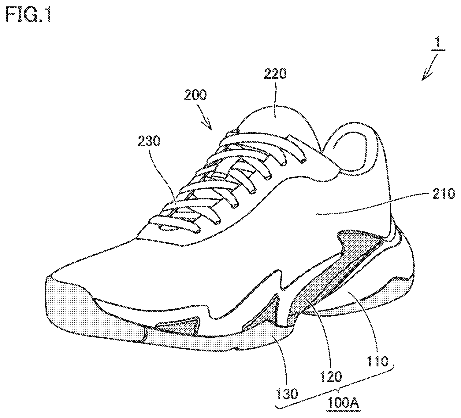
is a schematic perspective view of a shoe sole and a shoe including the shoe sole relating to Embodiment 1. First, a schematic configuration of a shoe 1 , and a shoe sole 100 A included in the shoe 1 , relating to the present embodiment will be described with reference to . Here, in , for ease of understanding, dark coloring is added to a reinforcing structure portion 120 , which will be described below, and light coloring is added to an outsole 130 , which will be described below (note that, this is the same for to , which will be described below).
As shown in , the shoe 1 includes the shoe sole 100 A and an upper 200 . The shoe sole 100 A is a member that covers a sole of a foot of a wearer, and has an approximate flat shape. The upper 200 has a bag-type shape that encloses the entire inserted foot of the wearer, and is located above the shoe sole 100 A.
The upper 200 has an upper body 210 , a shoe tongue 220 , and a shoelace 230 . The upper body 210 is a member that becomes a base of the upper 200 , and has a bag-type shape. The shoe tongue 220 and the shoelace 230 are both fixed or attached to the upper body 210 .
A bottom portion fixed to the shoe sole 100 A is located on a lower portion of the upper body 210 , and an opening portion, where an upper portion of an ankle and a part of the top of the foot are exposed, is provided on an upper portion of the upper body 210 . The shoe tongue 220 is fixed, by sewing, welding, bonding, or a combination thereof, to the upper body 210 so as to cover a portion of the opening portion provided in the upper body 210 where the top part of the foot is exposed. Woven or knitted fabric, synthetic leather, resin or the like is used, for example, as the upper body 210 and the shoe tongue 220 , and a double raschel warp knitted fabric with a polyester yarn knitted therein is used for a shoe that is required, in particular, to be air permeable and lightweight.
The shoelace 230 is a string-type member for pulling together peripheral edges of the opening portion, where a part of the top of the foot is exposed, provided in the upper body 210 , in a foot width direction, and is passed through a plurality of hole portions provided on the peripheral edges of the opening portion. The shoelace 230 is tightened in a state where the foot of the wearer is inserted into the upper body 210 , and the upper body 210 and the shoe tongue 220 can be brought into close contact with the foot.
The shoe sole 100 A has a midsole 110 , a reinforcing structure portion 120 , and an outsole 130 , and the midsole 110 from among these corresponds to a sole body. The midsole 110 , the reinforcing structure portion 120 , and the outsole 130 are integrated with each other, thereby the shoe sole 100 A has an overall approximate flat shape, such as stated above.
The outsole 130 has a ground contact surface 131 (refer to to ) on the lower surface thereof, and the midsole 110 is located above the outsole 130 . Moreover, the reinforcing structure portion 120 has a part thereof embedded in the midsole 110 , and another part located to be exposed from the midsole 110 .
is a perspective view of the shoe sole shown in , and and are a side surface view on a medial foot side and a side surface view on a lateral foot side, respectively, of the shoe sole shown in . is a bottom surface view of the shoe sole shown in , and (A) to (E) are cross-section views along a VIA-VIA line to a VIE-VIE line, respectively, shown in . Moreover, is an exploded perspective view of the shoe sole shown in , and and are a perspective view and a bottom surface view, respectively, showing a state where an outsole and a rear side midsole are removed from the shoe sole shown in . Next, a detailed structure of the shoe sole 100 A relating to the present embodiment will be described with reference to to .
As shown in to , the shoe sole 100 A is divided into a forefoot portion R 1 for supporting a toe portion and a ball portion of the foot of the wearer, a midfoot portion R 2 for supporting an arch portion of the foot of the wearer, and a rearfoot portion R 3 for supporting a heel portion of the foot of the wearer, along a front-rear direction (left-right direction in the figures in and , up-down direction in the figure in ) that is a direction coinciding with a foot length direction of the foot of the wearer in a plan view state.
Here, in the case where a front side end of the shoe sole 100 A is set as a reference, a location corresponding to a dimension of 40% of a dimension of the shoe sole 100 A in a front-rear direction from the front side end is set as a first boundary location, and a location corresponding to a dimension of 80% of a dimension of the shoe sole 100 A in the front-rear direction from the front side end is set as a second boundary location, the forefoot portion R 1 corresponds to a portion included between the front side end and the first boundary location along the front-rear direction, the midfoot portion R 2 corresponds to a portion included between the first boundary location and the second boundary location along the front-rear direction, and the rearfoot portion R 3 corresponds to a portion included between the second boundary location and a rear side end of the shoe sole along the front-rear direction.
Moreover, as shown in , the shoe sole 100 A is divided into a portion on a medial foot side (portion on the S 1 side shown in the figure) that is a medial side of the foot in an anatomical position (namely, a side close to a midline), and a portion on a lateral foot side (portion on the S 2 side shown in the figure) that is on an opposite side to the medial side of the foot in an anatomical position (namely, a side away from the midline), along a left-right direction (left-right direction in the figure) that is a direction coinciding with a foot width direction of the foot of the wearer in a plan view state. Here, a boundary line dividing the shoe sole 100 A into the portion on the medial foot side and the portion on the lateral foot side is a so-called shoe center. This shoe center, in the case where a standard wearer having a foot with a size suitable for the shoe 1 wears the shoe, is a straight line that can be obtained in the case where a straight line connecting a portion between a first toe and a second toe of the wearer and a calcaneal center portion is projected onto the shoe sole 100 A along the up-down direction.
With reference to to , the shoe sole 100 A has the midsole 110 , the reinforcing structure portion 120 , and the outsole 130 , such as stated above. The midsole 110 has an upper surface, a lower surface, and a side surface connecting the upper surface and the lower surface, and forms a portion of the shoe sole 100 A on an upper portion side. The outsole 130 has an upper surface, and a lower surface as the ground contact surface 131 such as stated above, and forms a portion of the shoe sole 100 A on a lower portion side. On the other hand, the reinforcing structure portion 120 is located so that a large portion thereof covers the lower surface of the midsole 110 .
The midsole 110 is located continuously from the forefoot portion R 1 to the rearfoot portion R 3 . The midsole 110 includes a front side midsole 110 A and a rear side midsole 110 B, and is formed by combining the front side midsole 110 A and the rear side midsole 110 B. The front side midsole 110 A is located straddling across the forefoot portion R 1 , the midfoot portion R 2 , and a portion near the front end of the rearfoot portion R 3 , and the rear side midsole 110 B is located straddling across a portion near the rear end of the midfoot portion R 2 , and the rearfoot portion R 3 .
Here, in a portion between the portion near the rear end of the midfoot portion R 2 and the portion near the front end of the rearfoot portion R 3 , the rear end portion of the front side midsole 110 A and the front end portion of the rear side midsole 110 B are overlapping in an up-down direction (namely, a direction orthogonal to both the above-stated front-rear direction and left-right direction) (in particular, refer to (D) , (E) , and ). In more detail, in this portion, the front side midsole 110 A and the rear side midsole 110 B are overlapping, so that the front side midsole 110 A is located on the upper 200 side and the rear side midsole 110 B is located on the outsole 130 side. In this way, in the forefoot portion R 1 and the portion near the front end of the midfoot portion R 2 , the midsole 110 is formed by the front side midsole 110 A, in the portion near the rear end of the midfoot portion R 2 and the portion near the front end of the rearfoot portion R 3 , the midsole 110 is formed by the overlapping portions of the front side midsole 110 A and the rear side midsole 110 B, and in the portion near the rear end of the rearfoot portion R 3 , the midsole 110 is formed by the rear side midsole 110 B.
The upper surface of the midsole 110 prescribes an upper surface of the shoe sole 100 A, and the peripheral edge thereof has a protruding shape compared to the surroundings (in particular, refer to , , and ). In this way, a concave-shaped portion is provided on the upper surface of the midsole 110 , and this concave-shaped portion becomes a portion in which the upper 200 is received. The portion on the upper surface of the midsole 110 , other than the peripheral edge that is a bottom surface of this concave-shaped portion, has a smooth curved surface shape so as to fit the sole of the wearer.
The outsole 130 , apart from a part of the midfoot portion R 2 , is located continuously from roughly the forefoot portion R 1 to the rearfoot portion R 3 . The outsole 130 includes a front side outsole 130 A, a rear medial foot side outsole 130 B 1 , and a rear lateral foot side outsole 130 B 2 . The front side outsole 130 A is located straddling across the forefoot portion R 1 and the portion near the front end of the midfoot portion R 2 , and the rear medial foot side outsole 130 B 1 and the rear lateral foot side outsole 130 B 2 are each located straddling across the portion near the rear end of the midfoot portion R 2 and the rearfoot portion R 3 . The rear medial foot side outsole 130 B 1 is located at a portion on the medial foot side from among the portion near the rear end of the midfoot portion R 2 and the rearfoot portion R 3 , and the rear lateral foot side outsole 130 B 2 is located at a portion on the lateral foot side from among the portion near the rear end of the midfoot portion R 2 and the rearfoot portion R 3 .
Since the lower surface of each of the front side outsole 130 A, the rear medial foot side outsole 130 B 1 , and the rear lateral foot side outsole 130 B 2 (namely, the lower surface of the outsole 130 ) forms the ground contact surface 131 such as stated above, in order to improve the grip performance, a tread pattern may be formed by having protrusions and recesses formed on an exposed surface thereof. Each of the front side outsole 130 A, the rear medial foot side outsole 130 B 1 , and the rear lateral foot side outsole 130 B 2 has an upper surface thereof joined to the lower surface of the midsole 110 .
It is preferable that the midsole 110 (namely, the front side midsole 110 A and the rear side midsole 110 B) is excellent in a shock absorbing performance while having a suitable strength, and from this viewpoint, for example, a foam material made of resin, which includes a resin material as a main component and a foaming agent and a crosslinking agent as secondary components, is used as the midsole 110 . Moreover, instead of this, a foam material made of rubber, which includes a rubber material as a main component and a plasticizer, a foaming agent, a reinforcing agent, and a crosslinking agent as secondary agents, may be used.
An ethylene-vinyl acetate copolymer (EVA), a polyolefin resin, a thermoplastic polyurethane, a thermoplastic polyamide elastomer (TPA, TPAE), or a thermoplastic polyester elastomer can be used, for example, as the resin material. Butadiene rubber can be suitably used, for example, as the rubber material.
In this way, the midsole 110 is generally formed by a member with a lower Young's modulus and more flexible than the outsole 130 . Note that, various types of shock absorbing parts may be included, and reinforcing parts other than the reinforcing structure portion 120 , which will be described below, may be included, at prescribed portions of the midsole 110 .
It is preferable that the outsole 130 (namely, the front side outsole 130 A, the rear medial foot side outsole 130 B 1 , and the rear lateral foot side outsole 130 B 2 ) is excellent in wear resistance and grip performance, and from this viewpoint, a member made of a material, which includes a rubber material as a main component and a plasticizer, a reinforcing agent, and a crosslinking agent as secondary agents, is used, for example, as the outsole 130 . Butadiene rubber can be suitably used, for example, as the rubber material.
In this way, the outsole 130 is generally formed by a member with a higher Young's modulus and harder than the midsole 110 . Note that, the shape of the outsole 130 and the above-stated tread pattern can be appropriately designed in accordance with a usage of the shoe 1 .
As shown in to , the reinforcing structure portion 120 is disposed so that a large portion thereof is located on the midfoot portion R 2 , while one part thereof reaches the forefoot portion R 1 and the rearfoot portion R 3 . The reinforcing structure portion 120 includes a first reinforcing member 120 A and a second reinforcing member 120 B. The first reinforcing member 120 A and the second reinforcing member 120 B are made of different members. The first reinforcing member 120 A is located on the medial foot side from the second reinforcing member 120 B, and the second reinforcing member 120 B is located on the lateral foot side from the first reinforcing member 120 A.
The first reinforcing member 120 A and the second reinforcing member 120 B are each made of a material higher in rigidity than the material forming the midsole 110 . Namely, the first reinforcing member 120 A and the second reinforcing member 120 B have a higher Young's modulus and are harder than the midsole 110 .
While the material forming the first reinforcing member 120 A and the second reinforcing member 120 B is not particularly limited, a non-fiber reinforced resin made of a polymer resin such as urethane-based thermoplastic elastomer (TPU), amide-based thermoplastic elastomer (TPA), ethylene-vinyl acetate copolymer (EVA) or the like, or a fiber reinforced resin using carbon fibers, glass fibers, aramid fibers, Dyneema fibers, Zylon fibers, boron fibers or the like as reinforcing fibers, for example, can be suitably used.
In addition to this, the first reinforcing member 120 A and the second reinforcing member 120 B may be made of rubber, or may be a same type of material as the material forming the midsole 110 , with the condition that the rigidity is higher than the midsole 110 . Note that, while forming the first reinforcing member 120 A and the second reinforcing member 120 B with a same type of material as the midsole 110 , it is assumed that the density is higher, for example, as a method of having the rigidity of these members higher than the midsole 110 .
Note that, in the shoe sole 100 A relating to the present embodiment, the material forming the first reinforcing member 120 A and the material forming the second reinforcing member 120 B are different materials. This point will be described in detail below.
The first reinforcing member 120 A is formed from an approximate plate shaped member having a prescribed thickness, and has a first base 121 A, a first bar 122 A, a lateral foot side first rising wall 123 A 1 , and a medial foot side first rising wall 123 A 2 .
The first base 121 A is located at a portion of the midfoot portion R 2 on the medial foot side, and extends in roughly the front-rear direction along an edge portion of the front side midsole 110 A on the medial foot side at a portion corresponding to the midfoot portion R 2 . The first base 121 A has an approximate plate shape that covers a lower surface of the front side midsole 110 A.
The first bar 122 A has an elongated approximate plate shape that covers the lower surface of the front side midsole 110 A, and is disposed so as to reach a portion near the rear end of the midfoot portion R 2 on the medial foot side from a portion near the front end of the forefoot portion R 1 on the lateral foot side. In this way, the portion of the first bar 122 A disposed in the midfoot portion R 2 extends along an oblique direction crossing both the front-rear direction and the left-right direction, such that a front end thereof is located on the lateral foot side and a rear end thereof is located on the medial foot side.
The rear end portion of the first bar 122 A is connected to the first base 121 A. In other words, the first bar 122 A is provided so as to extend continuously from the first base 121 A.
The lateral foot side first rising wall 123 A 1 , which has an approximate plate shape, is provided on the front end portion of the first bar 122 A. The lateral foot side first rising wall 123 A 1 is erected along a side surface of the front side midsole 110 A on the lateral foot side from the front end portion of the first bar 122 A. In this way, the lateral foot side first rising wall 123 A 1 covers a part of the side surface of the midsole 110 on the lateral foot side.
The medial foot side first rising wall 123 A 2 , which has an approximate plate shape, is provided on the end portion of the first base 121 A on the medial foot side. The medial foot side first rising wall 123 A 2 is erected along a side surface of the front side midsole 110 A on the medial foot side from the end portion of the first base 121 A on the medial foot side. In this way, the medial foot side first rising wall 123 A 2 covers a part of the side surface of the midsole 110 on the medial foot side.
The first reinforcing member 120 A formed of the above-stated first base 121 A, first bar 122 A, lateral foot side first rising wall 123 A 1 , and medial foot side first rising wall 123 A 2 is connected to the lower surface and the side surface of the front side midsole 110 A. Note that, in the present embodiment, a concave shaped first housing portion 111 A (refer to ), which has a shape corresponding to the first reinforcing member 120 A, is formed on the lower surface and the side surface of the front side midsole 110 A, and the first reinforcing member 120 A is connected to the front side midsole 110 A and the rear side midsole 110 B in a state where housed in this first housing portion 111 A.
The second reinforcing member 120 B is formed from an approximate plate shaped member having a prescribed thickness, and has a second base 121 B, a second bar 122 B, a front side second rising wall 123 B 1 , and a rear side second rising wall 123 B 2 .
The second base 121 B is located at a portion of the midfoot portion R 2 on the lateral foot side, and extends in roughly the front-rear direction along an edge portion of the front side midsole 110 A on the lateral foot side at a portion corresponding to the midfoot portion R 2 . The second base 121 B has an approximate plate shape that covers a lower surface of the front side midsole 110 A.
The second bar 122 B has an elongated approximate plate shape that covers the lower surface of the front side midsole 110 A, and is disposed so as to reach a portion near the rear end of the midfoot portion R 2 on the medial foot side from a portion near the rear end of the forefoot portion R 1 on the lateral foot side. In this way, the portion of the second bar 122 B disposed in the midfoot portion R 2 extends along an oblique direction crossing both the front-rear direction and the left-right direction, such that a front end thereof is located on the lateral foot side and a rear end thereof is located on the medial foot side.
An intermediate portion excluding the front end portion and the rear end portion of the second bar 122 B is connected to the second base 121 B. In other words, the second bar 122 B is provided so as to extend continuously from the second base 121 B.
The front side second rising wall 123 B 1 , which has an approximate plate shape, is provided on the front end portion of the second bar 122 B. The front side second rising wall 123 B 1 is erected along a side surface of the front side midsole 110 A on the lateral foot side from the front end portion of the second bar 122 B. In this way, the front side second rising wall 123 B 1 covers a part of the side surface of the midsole 110 on the lateral foot side.
The rear side second rising wall 123 B 2 , which has an approximate plate shape, is provided on the end portion of the second base 121 B on the lateral foot side. The rear side second rising wall 123 B 2 is erected along a side surface of the front side midsole 110 A on the lateral foot side from the end portion of the second base 121 B on the lateral foot side. In this way, the rear side second rising wall 123 B 2 covers a part of the side surface of the midsole 110 on the lateral foot side.
The second reinforcing member 120 B formed of the above-stated second base 121 B, second bar 122 B, front side second rising wall 123 B 1 , and rear side second rising wall 123 B 2 is connected to the lower surface and the side surface of the front side midsole 110 A. Note that, in the present embodiment, a concave shaped second housing portion 111 B (refer to ), which has a shape corresponding to the second reinforcing member 120 B, is formed on the lower surface and the side surface of the front side midsole 110 A, and the second reinforcing member 120 B is connected to the front side midsole 110 A and the rear side midsole 110 B in a state where housed in this second housing portion 111 B.
Here, the first bar 122 A of the first reinforcing member 120 A and the second bar 122 B of the second reinforcing member 120 B are disposed with a distance therebetween in the front-rear direction and the left-right direction. In this way, the first bar 122 A and the second bar 122 B are located with a distance therebetween, in particular, in the midfoot portion R 2 .
Accordingly, an interposed portion 112 , which is formed by a part of the midsole 110 (more strictly, a part of the front side midsole 110 A) made of a material lower in rigidity than the first reinforcing member 120 A and the second reinforcing member 120 B, is located at a portion between the first bar 122 A and the second bar 122 B, in particular, in the midfoot portion R 2 . This interposed portion 112 is a part of the midsole 110 at a portion where the reinforcing structure portion 120 is not provided.
This interposed portion 112 extends along a same direction as the direction in which the first bar 122 A and the second bar 122 B extend. In more detail, the portion of the interposed portion 112 disposed in the midfoot portion R 2 extends along an oblique direction crossing both the front-rear direction and the left-right direction, such that a front end thereof is located on the lateral foot side and a rear end thereof is located on the medial foot side.
As shown in , in the shoe sole 100 A relating to the present embodiment, the above-stated first reinforcing member 120 A and second reinforcing member 120 B are assembled on the front side midsole 110 A, prior to the front side midsole 110 A and the rear side midsole 110 B being combined. Accordingly, after the rear side midsole 110 B is assembled with the front side midsole 110 A, it becomes a state where the portion of the rear end portion of the first reinforcing member 120 A excluding the medial foot side first rising wall 123 A 2 , and the portion of the rear end portion of the second reinforcing member 120 B excluding the rear side second rising wall 123 B 2 , are sandwiched by the front side midsole 110 A and the rear side midsole 110 B, such as shown in (D) and (E) , and these portions are embedded in the midsole 110 , thereby no longer being exposed to the outside.
Moreover, the rear end portion of the interposed portion 112 of the front side midsole 110 A, which is located between the first bar 122 A of the first reinforcing member 120 A and the second bar 122 B of the second reinforcing member 120 B, is covered by the rear side midsole 110 B, such as shown in (D) , and this portion is no longer exposed to the outside.
In addition, as shown in , in the shoe sole 100 A relating to the present embodiment, after the rear side midsole 110 B is assembled with the front side midsole 110 A, the front side outsole 130 A, the rear medial foot side outsole 130 B 1 , and the rear lateral foot side outsole 130 B 2 are respectively assembled with the midsole 110 . In this way, it becomes a state where the portion of the front end part of the first reinforcing member 120 A excluding the lateral foot side first rising wall 123 A 1 , and the portion of the front end portion of the second reinforcing member 120 B excluding the front side second rising wall 123 B 1 , are sandwiched by the front side midsole 110 A and the front side outsole 130 A, such as shown in (A) and (B) , and these portions are no longer exposed to the outside.
Moreover, the front end portion of the interposed portion 112 of the front side midsole 110 A, which is located between the first bar 122 A of the first reinforcing member 120 A and the second bar 122 B of the second reinforcing member 120 B, is covered by the front side outsole 130 A, such as shown in (B) , and this portion is no longer exposed to the outside.
Note that, while the connections between each of the front side midsole 110 A, the rear side midsole 110 B, the first reinforcing member 120 A, the second reinforcing member 120 B, the front side outsole 130 A, the rear medial foot side outsole 130 B 1 , and the rear lateral foot side outsole 130 B 2 may be performed by any type of method, they can be performed, for example, by adhesion or the like.
In the above-described shoe 1 and the shoe sole 100 A included in the shoe 1 relating to the present embodiment, the portions of the first bar 122 A and the second bar 122 B disposed in the midfoot portion R 2 extend along an oblique direction crossing both the front-rear direction and the left-right direction, such that a front end thereof is located on the lateral foot side and a rear end thereof is located on the medial foot side, and the portions of the first bar 122 A and the second bar 122 B disposed in the midfoot portion R 2 are located with a distance therebetween. In this way, the interposed portion 112 formed from a part of the midsole 110 is disposed between the first bar 122 A and the second bar 122 B.
Accordingly, by being formed in such a manner, twisting easily occurs between a portion of the forefoot portion R 1 on the medial foot side and a portion of the rearfoot portion R 3 on the lateral foot side, around an axis in a direction where the interposed portion 112 extends, at the location where the interposed portion 112 is provided. Therefore, in association with this, an impulse of brake at the time of a cutting maneuver increases, and as a result, a swift and smooth cutting maneuver can be realized.
Moreover, by being formed in such a manner, the first bar 122 A and the second bar 122 B are disposed extending in a direction crossing the left-right direction. Therefore, a bending stiffness against dorsal flexion of the shoe sole 100 A around an axis in the left-right direction also increases, and as a result of this, a function for assisting a start-off at the time of a cutting maneuver (namely, an acceleration assisting function), and a function for increasing a propulsive force to the front at the time of traveling (namely, a travel assisting function), also improve.
In addition, by being formed in such a manner, the first bar 122 A and the second bar 122 B are disposed in the midfoot portion R 2 , thereby arch sinking can be prevented by having the arch portion of the foot of the wearer supported by the first bar 122 A and the second bar 122 B, and a function for maintaining an arch of the foot of the wearer is exhibited.
In addition, as stated above, the reinforcing structure portion 120 is formed by being divided into the first reinforcing member 120 A that includes the first bar 122 A and the second reinforcing member 120 B that includes the second bar 122 B, thereby it becomes possible to easily adjust the performance, compared to the case where the reinforcing structure portion 120 is made of a single member. Namely, in the case where the reinforcing structure portion 120 is made of a single member, it becomes difficult to provide an extreme rigidity difference, for example, between the medial foot side and the lateral foot side. Therefore, this reinforcing structure portion 120 is formed by being divided into the first reinforcing member 120 A and the second reinforcing member 120 B, which are different members, thereby an adjustment of providing such an extreme rigidity difference between the medial foot side and the lateral foot side can be performed relatively easily.
Moreover, in the case where the reinforcing structure portion 120 is made of a single member, a part of the reinforcing structure portion 120 (namely, a connection portion or the like that connects the first bar 122 A and the second bar 122 B) is naturally included in the portion that becomes the above-stated axis of twisting. Therefore, the reinforcing structure portion 120 is formed by being dividing into the first reinforcing member 120 A and the second reinforcing member 120 B, which are different members, thereby it becomes possible to be formed so that the reinforcing structure portion 120 is not located in the portion that becomes an axis of twisting, an adjustment of the performance is simplified for this point, and by extension, a swift and smooth cutting maneuver is further promoted.
Here, in the shoe 1 and the shoe sole 100 A included in the shoe 1 relating to the present embodiment, the material forming the first reinforcing member 120 A and the material forming the second reinforcing member 120 B are different materials, such as stated above. By being formed in such a manner, it becomes possible to provide a rigidity difference between the first bar 122 A and the second bar 122 B. Therefore, by making these materials different, it becomes possible, at the time of a cutting maneuver, to variously adjust the extent of twisting occurring between a portion of the forefoot portion R 1 on the medial foot side and a portion of the rearfoot portion R 3 on the lateral foot side, around an axis in a direction where the interposed portion 112 extends, at the location where the interposed portion 112 is provided. Therefore, an optimal design according to a usage of the shoe can be performed.
The selection of materials at this time can be freely selected, with the condition that the first reinforcing member 120 A and the second reinforcing member 120 B are both formed of a material higher in rigidity than the material forming the midsole 110 . More specifically, even in the case where it is possible to select a material type different from the above-stated various types of materials, and the same type of material is selected, the above-stated rigidity difference can be exhibited, by providing a difference in density or the like between these materials.
In particular, if a rigidity difference between the material forming the first reinforcing member 120 A and the material forming the second reinforcing member 120 B is large, providing an extreme rigidity difference between the medial foot side and the lateral foot side can be very easily performed. Therefore, it becomes possible to easily manufacture a shoe sole, in which a reinforcing structure portion is provided that exhibits a desired performance in accordance with a usage, and a shoe including the shoe sole.
Note that, a difference in rigidity between the first bar 122 A and the second bar 122 B can be further provided, by making the material forming the first reinforcing member 120 A and the material forming the second reinforcing member 120 B different materials, and variously modifying the thickness, width, and shape of the first bar 122 A, and the thickness, width, and shape of the second bar 122 B.
Therefore, by having the shoe 1 and the shoe sole 100 A included in the shoe 1 relating to the present embodiment, it becomes possible to easily manufacture a shoe sole, in which a reinforcing structure portion is provided that exhibits a desired performance in accordance with a usage, and a shoe including the shoe sole. In addition, in the case of having the shoe 1 and the shoe sole 100 A included in the shoe 1 relating to the present embodiment, it is possible to individually provide changes to the performance of the reinforcing structure portion in accordance with not only a usage, by also by the wearer, and a shoe sole and shoe superior to a conventional shoe sole and shoe can be produced for this point.
Here, in the shoe 1 and the shoe sole 100 A included in the shoe 1 relating to the present embodiment, the first bar 122 A and the second bar 122 B are both provided so that a front end thereof reaches the forefoot portion R 1 , and the portions of the first bar 122 A and second bar 122 B located in the forefoot portion R 1 both extend crossing a portion corresponding to a metatarsophalangeal joint of the foot of the wearer (the portion shown by reference character MP within ). In the case of being formed in such a manner, a larger propulsive force can be obtained by the resilience of the first bar 122 A and the second bar 122 B, which elastically deform in accordance with dorsal flexion of the shoe sole 100 A at take-off, and thereby the above-stated acceleration assisting function and travel assisting function are further improved.
Moreover, in the shoe 1 and the shoe sole 100 A included in the shoe 1 relating to the present embodiment, in addition to the first bar 122 A, the first base 121 A, lateral foot side first rising wall 123 A 1 , and medial foot side first rising wall 123 A 2 are provided in the first reinforcing member 120 A, and in addition to the second bar 122 B, the second base 121 B, front side second rising wall 123 B 1 , and rear side second rising wall 123 B 2 are provided in the second reinforcing member 120 B. In the case of being formed in such a manner, the overall strength of the shoe sole 100 A is improved, it becomes possible to increase a contact area between the first reinforcing member 120 A and second reinforcing member 120 B and the midsole 110 and outsole 130 , and it becomes possible to increase a connection strength between these members. Therefore, a shoe sole and shoe excellent in durability can be produced.
In addition, in the shoe 1 and the shoe sole 100 A included the shoe 1 relating to the present embodiment, the midsole 110 is divided into the front side midsole 110 A and the rear side midsole 110 B, thereby the portion of the rear end portion of the first reinforcing member 120 A excluding the medial foot side first rising wall 123 A 2 , and the portion of the rear end portion of the second reinforcing member 120 B excluding the rear side second rising wall 123 B 2 , are embedded in the midsole 110 by being sandwiched by the front side midsole 110 A and the rear side midsole 110 B. In the case of being formed in such a manner, since the members in this portion are disposed from the ground contact surface 131 side in the order of the outsole 130 , the midsole 110 , and the reinforcing structure portion 120 , a shock absorbing function is maximized.
First Modified Example
(A) to (C) show a bottom surface view, a side surface view of a medial foot side, and a side surface view of a lateral foot side, respectively, which omit an illustration of an outsole, of a shoe sole relating to a first modified example. Hereinafter, a shoe sole 100 A 1 relating to the first modified example based on the above-stated Embodiment 1 will be described, with reference to . Note that, the shoe sole 100 A 1 relating to this modified example is included in the shoe 1 , instead of the shoe sole 100 A relating to the above-stated Embodiment 1.
As shown in (A) to (C) , the shoe sole 100 A 1 , in the case where compared with the shoe sole 100 A relating to the above-stated Embodiment 1, has a configuration that is different for the point of the first reinforcing member 120 A does not have the lateral foot side first rising wall 123 A 1 and the medial foot side first rising wall 123 A 2 , and for the point of the second reinforcing member 120 B does not have the front side second rising wall 123 B 1 and the rear side second rising wall 123 B 2 . Note that, in the shoe sole 100 A 1 , similar to the shoe sole 100 A relating to the above-stated Embodiment 1, the material forming the first reinforcing member 120 A and the material forming the second reinforcing member 120 B are different.
In the case of being formed in such a manner, an effect can be obtained that conforms to the effect described in the above-stated Embodiment 1, in particular, an effect can be obtained where a shoe sole, in which a reinforcing structure portion is provided that exhibits a desired performance in accordance with a usage, and a shoe including the shoe sole, can be easily manufactured.
Second Modified Example
(A) to (C) show a bottom surface view, a side surface view of a medial foot side, and a side surface view of a lateral foot side, respectively, which omit an illustration of an outsole, of a shoe sole relating to a second modified example. Hereinafter, a shoe sole 100 A 2 relating to the second modified example based on the above-stated Embodiment 1 will be described, with reference to . Note that, the shoe sole 100 A 2 relating to this modified example is included in the shoe 1 , instead of the shoe sole 100 A relating to the above-stated Embodiment 1.
As shown in (A) to (C) , the shoe sole 100 A 2 , in the case where compared with the shoe sole 100 A relating to the above-stated Embodiment 1, has a configuration that is different mainly for the shape of the first bar 122 A included in the first reinforcing member 120 A. Specifically, in the shoe sole 100 A 2 , the front end of the first bar 122 A is located at a portion near the rear end of the forefoot portion R 1 on the lateral foot side, and does not reach the portion near the front end of the forefoot portion R 1 on the lateral foot side. In accordance with this, the first reinforcing member 120 A does not have the lateral foot side first rising wall 123 A 1 . Note that, in the shoe sole 100 A 2 , similar to the shoe sole 100 A relating to the above-stated Embodiment 1, the material forming the first reinforcing member 120 A and the material forming the second reinforcing member 120 B are different.
In the case of being formed in such a manner, an effect can be obtained that conforms to the effect described in the above-stated Embodiment 1, in particular, an effect can be obtained where a shoe sole, in which a reinforcing structure portion is provided that exhibits a desired performance in accordance with a usage, and a shoe including the shoe sole, can be easily manufactured.
Third Modified Example
(A) to (C) show a bottom surface view, a side surface view of a medial foot side, and a side surface view of a lateral foot side, respectively, which omit an illustration of an outsole, of a shoe sole relating to a third modified example. Hereinafter, a shoe sole 100 A 3 relating to the third modified example based on the above-stated Embodiment 1 will be described, with reference to . Note that, the shoe sole 100 A 3 relating to this modified example is included in the shoe 1 , instead of the shoe sole 100 A relating to the above-stated Embodiment 1.
As shown in (A) to (C) , the shoe sole 100 A 3 , in the case where compared with the shoe sole 100 A relating to the above-stated Embodiment 1, has a configuration that is different mainly for the point of the first reinforcing member 120 A has an additional first bar 122 A′ in addition to the first bar 122 A. Note that, in the shoe sole 100 A 3 , similar to the shoe sole 100 A relating to the above-stated Embodiment 1, the material forming the first reinforcing member 120 A and the material forming the second reinforcing member 120 B are different.
Specifically, the additional first bar 122 A′ has an elongated approximate plate shape that covers the lower surface of the front side midsole 110 A, and is disposed so as to reach a portion near the front end of the midfoot portion R 2 on the medial foot side from the portion near the front end of the forefoot portion R 1 on the lateral foot side. In this way, the portion of the additional first bar 122 A′ disposed in the midfoot portion R 2 extends along an oblique direction crossing both the front-rear direction and the left-right direction, such that a front end thereof is located on the lateral foot side and a rear end thereof is located on the medial foot side. Note that, the additional first bar 122 A′ is located on the medial foot side from the first bar 122 A.
The rear end portion of the additional first bar 122 A′ is connected to the first base 121 A. In other words, the additional first bar 122 A′ is provided so as to extend continuously from the first base 121 A.
Here, the first bar 122 A and the additional first bar 122 A′ of the first reinforcing member 120 A are disposed with a distance therebetween in both the front-rear direction and the left-right direction. In this way, the first bar 122 A and the additional first bar 122 A′ are located with a distance therebetween, in particular, in the midfoot portion R 2 .
Accordingly, an additional interposed portion 112 ′, which is formed by a part of the midsole 110 (more strictly, a part of the front side midsole 110 A) made of a material lower in rigidity than the first reinforcing member 120 A, is located at a portion between the first bar 122 A and the additional first bar 122 A′, in particular, in the midfoot portion R 2 . This additional interposed portion 112 ′ is a part of the midsole 110 at a portion where the reinforcing structure portion 120 is not provided.
This additional interposed portion 112 ′ extends along a same direction as the direction in which the first bar 122 A and the additional first bar 122 A′ extend. In more detail, the portion of the additional interposed portion 112 ′ disposed in the midfoot portion R 2 extends along an oblique direction crossing both the front-rear direction and the left-right direction, such that a front end thereof is located on the lateral foot side and a rear end thereof is located on the medial foot side.
Accordingly, in the case of being formed in such a manner, twisting easily occurs between a portion of the forefoot portion R 1 on the medial foot side and a portion of the rearfoot portion R 3 on the lateral foot side, not only around an axis in a direction where the interposed portion 112 extends, but also around an axis in a direction where the additional interposed portion 112 ′ extends, at the location where the interposed portion 112 is provided and the location where the additional interposed portion 112 ′ is provided. Therefore, in association with this, an impulse of brake at the time of a cutting maneuver increases, and as a result, a swift and smooth cutting maneuver can be realized.
Moreover, in the case of being formed in such a manner, the additional first bar 122 A′, in addition to the first bar 122 A and the second bar 122 B, is disposed extending in a direction crossing the left-right direction. Therefore, a bending stiffness against dorsal flexion of the shoe sole 100 A 3 around an axis in the left-right direction also increases, and as a result of this, a function for assisting a start-off at the time of a cutting maneuver (namely, an acceleration assisting function), and a function for increasing a propulsive force to the front at the time of traveling (namely, a travel assisting function), also improve.
Therefore, in the case of being formed in such a manner, not only the effect described in the above-stated Embodiment 1 can be obtained, but also an effect can be obtained where a shoe sole with a higher performance, and a shoe including the shoe sole, can be produced.
Fourth Modified Example
(A) to (C) show a bottom surface view, a side surface view of a medial foot side, and a side surface view of a lateral foot side, respectively, which omit an illustration of an outsole, of a shoe sole relating to a fourth modified example. Hereinafter, a shoe sole 100 A 4 relating to the fourth modified example based on the above-stated Embodiment 1 will be described, with reference to . Note that, the shoe sole 100 A 4 relating to this modified example is included in the shoe 1 , instead of the shoe sole 100 A relating to the above-stated Embodiment 1.
As shown in (A) to (C) , the shoe sole 100 A 4 , in the case where compared with the shoe sole 100 A relating to the above-stated Embodiment 1, has a configuration that is different mainly for the point of the second reinforcing member 120 B has an additional second bar 122 B′ in addition to the second bar 122 B. Note that, in the shoe sole 100 A 4 , similar to the shoe sole 100 A relating to the above-stated Embodiment 1, the material forming the first reinforcing member 120 A and the material forming the second reinforcing member 120 B are different.
Specifically, the additional second bar 122 B′ has an elongated approximate plate shape that covers the lower surface of the front side midsole 110 A, and is disposed so as to reach a portion near the rear end of the rearfoot portion R 3 on the medial foot side from a portion near the rear end of the midfoot portion R 2 on the lateral foot side. In this way, the portion of the additional second bar 122 B′ disposed in the midfoot portion R 2 extends along an oblique direction crossing both the front-rear direction and the left-right direction, such that a front end thereof is located on the lateral foot side and a rear end thereof is located on the medial foot side. Note that, the additional second bar 122 B′ is located on the lateral foot side from the second bar 122 B.
The front end portion of the additional second bar 122 B′ is connected to the second base 121 B. In other words, the additional second bar 122 B′ is provided so as to extend continuously from the second base 121 B.
Here, the second bar 122 B and the additional second bar 122 B′ of the second reinforcing member 120 B are disposed with a distance therebetween in both the front-rear direction and the left-right direction. In this way, the second bar 122 B and the additional second bar 122 B′ are located with a distance therebetween, in particular, in the midfoot portion R 2 .
Accordingly, an additional interposed portion 112 ″, which is formed by a part of the midsole 110 (more strictly, a part of the front side midsole 110 A) made of a material lower in rigidity than the second reinforcing member 120 B, is located at a portion between the second bar 122 B and the additional second bar 122 B′, in particular, in the midfoot portion R 2 . This additional interposed portion 112 ″ is a part of the midsole 110 at a portion where the reinforcing structure portion 120 is not provided.
This additional interposed portion 112 ″ extends along a same direction as the direction in which the second bar 122 B and the additional second bar 122 B′ extend. In more detail, the portion of the additional interposed portion 112 ″ disposed in the midfoot portion R 2 extends along an oblique direction crossing both the front-rear direction and the left-right direction, such that a front end thereof is located on the lateral foot side and a rear end thereof is located on the medial foot side.
Accordingly, in the case of being formed in such a manner, twisting easily occurs between a portion of the forefoot portion R 1 on the medial foot side and a portion of the rearfoot portion R 3 on the lateral foot side, not only around an axis in a direction where the interposed portion 112 extends, but also around an axis in a direction where the additional interposed portion 112 ″ extends, at the location where the interposed portion 112 is provided and the location where the additional interposed portion 112 ″ is provided. Therefore, in association with this, an impulse of brake at the time of a cutting maneuver increases, and as a result, a swift and smooth cutting maneuver can be realized.
Therefore, in the case of being formed in such a manner, not only the effect described in the above-stated Embodiment 1 can be obtained, but also an effect can be obtained where a shoe sole with a higher performance, and a shoe including the shoe sole, can be produced.
Fifth Modified Example
(A) to (C) show a bottom surface view, a side surface view of a medial foot side, and a side surface view of a lateral foot side, respectively, which omit an illustration of an outsole, of a shoe sole relating to a fifth modified example. Hereinafter, a shoe sole 100 A 5 relating to the fifth modified example based on the above-stated Embodiment 1 will be described, with reference to . Note that, the shoe sole 100 A 5 relating to this modified example is included in the shoe 1 , instead of the shoe sole 100 A relating to the above-stated Embodiment 1.
As shown in (A) to (C) , the shoe sole 100 A 5 , in the case where compared with the shoe sole 100 A relating to the above-stated Embodiment 1, has a configuration that is different mainly for the shape of the second reinforcing member 120 B. Specifically, in the shoe sole 100 A 5 , the second bar 122 B is located so as to reach a portion near the rear end of the midfoot portion R 2 on the lateral foot side from a portion near the rear end of the forefoot portion R 1 on the lateral foot side. In this way, the portion of the second bar 122 B disposed in the midfoot portion R 2 extends along roughly the front-rear direction, such that a front end thereof is located on the lateral foot side and a rear end thereof is located on the lateral foot side. Note that, in the shoe sole 100 A 5 , similar to the shoe sole 100 A relating to the above-stated Embodiment 1, the material forming the first reinforcing member 120 A and the material forming the second reinforcing member 120 B are different.
In the case of being formed in such a manner, an effect can be obtained that conforms to the effect described in the above-stated Embodiment 1, in particular, an effect can be obtained where a shoe sole, in which a reinforcing structure portion is provided that exhibits a desired performance in accordance with a usage, and a shoe including the shoe sole, can be easily manufactured.
Sixth Modified Example
(A) to (C) show a bottom surface view, a side surface view of a medial foot side, and a side surface view of a lateral foot side, respectively, which omit an illustration of an outsole, of a shoe sole relating to a sixth modified example. Hereinafter, a shoe sole 100 A 6 relating to the sixth modified example based on the above-stated Embodiment 1 will be described, with reference to . Note that, the shoe sole 100 A 6 relating to this modified example is included in the shoe 1 , instead of the shoe sole 100 A relating to the above-stated Embodiment 1.
As shown in (A) to (C) , the shoe sole 100 A 6 , in the case where compared with the shoe sole 100 A relating to the above-stated Embodiment 1, has a configuration that is different mainly for the shape of the first reinforcing member 120 A. Specifically, in the shoe sole 100 A 6 , the first bar 122 A is located so as to reach a portion near the rear end of the midfoot portion R 2 on the medial foot side from a portion near the rear end of the forefoot portion R 1 on the medial foot side. In this way, the portion of the first bar 122 A disposed in the midfoot portion R 2 extends along roughly the front-rear direction, such that a front end thereof is located on the medial foot side and a rear end thereof is located on the medial foot side. Note that, in the shoe sole 100 A 6 , similar to the shoe sole 100 A relating to the above-stated Embodiment 1, the material forming the first reinforcing member 120 A and the material forming the second reinforcing member 120 B are different.
In the case of being formed in such a manner, an effect can be obtained that conforms to the effect described in the above-stated Embodiment 1, in particular, an effect can be obtained where a shoe sole, in which a reinforcing structure portion is provided that exhibits a desired performance in accordance with a usage, and a shoe including the shoe sole, can be easily manufactured.
Seventh Modified Example
(A) to (C) show a bottom surface view, a side surface view of a medial foot side, and a side surface view of a lateral foot side, respectively, which omit an illustration of an outsole, of a shoe sole relating to a seventh modified example. Hereinafter, a shoe sole 100 A 7 relating to the seventh modified example based on the above-stated Embodiment 1 will be described, with reference to . Note that, the shoe sole 100 A 7 relating to this modified example is included in the shoe 1 , instead of the shoe sole 100 A relating to the above-stated Embodiment 1.
As shown in (A) to (C) , the shoe sole 100 A 7 , in the case where compared with the shoe sole 100 A relating to the above-stated Embodiment 1, has a configuration that is different for the midsole 110 . Specifically, in the shoe sole 100 A 7 , the midsole 110 is formed by a single member, and this is not divided into the front side midsole 110 A and the rear side midsole 110 B. Accordingly, the above-stated first reinforcing member 120 A and second reinforcing member 120 B do not have a part thereof embedded in the midsole 110 , and the entire part thereof is disposed on the lower surface and the side surface of the midsole 110 . Note that, in the shoe sole 100 A 7 , similar to the shoe sole 100 A relating to the above-stated Embodiment 1, the material forming the first reinforcing member 120 A and the material forming the second reinforcing member 120 B are different.
In the case of being formed in such a manner, an effect can be obtained that conforms to the effect described in the above-stated Embodiment 1, in particular, an effect can be obtained where a shoe sole, in which a reinforcing structure portion is provided that exhibits a desired performance in accordance with a usage, and a shoe including the shoe sole, can be easily manufactured.
Embodiment 2
is a bottom surface view of a shoe sole relating to Embodiment 2, and is an exploded perspective view of the shoe sole shown in . Moreover, is a bottom surface view showing a state where an outsole is removed from the shoe sole shown in . Hereinafter, a shoe sole 100 B relating to the present embodiment will be described, with reference to to . Note that, the shoe sole 100 B relating to the present embodiment is included in the shoe 1 , instead of the shoe sole 100 A relating to Embodiment 1.
As shown in and , while the shoe sole 100 B, similar to the shoe sole 100 A relating to the above-stated Embodiment 1, has the midsole 110 , the reinforcing structure portion 120 , and the outsole 130 , the configuration of each of these is different to that of the shoe sole 100 A relating to the above-stated Embodiment 1.
In the shoe sole 100 B, the midsole 110 as a sole body is made of a single member, and this midsole 110 made of a single member is located continuously from the forefoot portion R 1 to the rearfoot portion R 3 . The outsole 130 includes a front side outsole 130 A and a rear side outsole 130 B, and the outsole 130 formed from the front side outsole 130 A and the rear side outsole 130 B, apart from a part of the midfoot portion R 2 , is located continuously from roughly the forefoot portion R 1 to the rearfoot portion R 3 .
The reinforcing structure portion 120 includes a first reinforcing member 120 A, and a second reinforcing member 120 B made of a different member from the first reinforcing member 120 A. The first reinforcing member 120 A is located on the medial foot side from the second reinforcing member 120 B, and the second reinforcing member 120 B is located on the lateral foot side from the first reinforcing member 120 A.
The first reinforcing member 120 A and the second reinforcing member 120 B are both formed of a material higher in rigidity than the material forming the midsole 110 . Namely, the first reinforcing member 120 A and the second reinforcing member 120 B have a higher Young's modulus and are harder than the midsole 110 . Here, in the shoe sole 100 B, similar to the shoe sole 100 A relating to the above-stated Embodiment 1, the material forming the first reinforcing member 120 A and the material forming the second reinforcing member 120 B are different. Note that, the first reinforcing member 120 A is embedded in the midsole 110 beforehand by insert molding, two-color molding or the like.
As shown in to , the first reinforcing member 120 A has a first base 121 A, a first bar 122 A, an additional first bar 122 A′, and a first rising wall 123 A. On the other hand, the second reinforcing member 120 B has a second base 121 B, a second bar 122 B, and a second rising wall 123 B.
The first bar 122 A is disposed so as to reach a portion near the rear end of the midfoot portion R 2 on the medial foot side from a portion near the front end of the midfoot portion R 2 on the lateral foot side. In this way, the first bar 122 A extends along an oblique direction crossing both the front-rear direction and the left-right direction, such that a front end thereof is located on the lateral foot side and a rear end thereof is located on the medial foot side.
The additional first bar 122 A′ is disposed so as to reach a portion near the front end of the midfoot portion R 2 on the medial foot side from a portion near the rear end of the forefoot portion R 1 on the lateral foot side. In this way, the portion of the additional first bar 122 A′ disposed in the midfoot portion R 2 extends along an oblique direction crossing both the front-rear direction and the left-right direction, such that a front end thereof is located on the lateral foot side and a rear end thereof is located on the medial foot side. Note that, the additional first bar 122 A′ is located on the medial foot side from the first bar 122 A.
The rear end portion of the first bar 122 A and the rear end portion of the additional first bar 122 A′ are both connected to the first base 121 A. The first base 121 A extends in roughly the front-rear direction along an edge portion of the midfoot portion R 2 on the medial foot side. Moreover, the first rising wall 123 A is provided at an end portion of the first base 121 A on the medial foot side so as to cover a part of the side surface of the midsole 110 on the medial foot side.
The second bar 122 B is disposed so as to reach a portion near the rear end of the midfoot portion R 2 on the medial foot side from a portion near the front end of the midfoot portion R 2 on the lateral foot side. In this way, the second bar 122 B extends along an oblique direction crossing both the front-rear direction and the left-right direction, such that a front end thereof is located on the lateral foot side and a rear end thereof is located on the medial foot side.
The front end portion of the second bar 122 B is connected to the second base 121 B. The second base 121 B extends in roughly the front-rear direction along an edge portion of the midfoot portion R 2 on the lateral foot side. Moreover, the second rising wall 123 B is provided at an end portion of the second base 121 B on the lateral foot side so as to cover a part of the side surface of the midsole 110 on the lateral foot side, and the second rising wall 123 B reaches a portion near the rear end of the forefoot portion R 1 on the lateral foot side (namely, the side surface and the lower surface of this portion).
Here, the rear end portion of the second bar 122 B overlaps the rear end portion of the first base 121 A. In this way, an overlapping region OL, in which a part of the first reinforcing member 120 A and a part of the second reinforcing member 120 B are overlapping in the up-down direction, is formed in a portion near the rear end of the midfoot portion R 2 on the medial foot side.
The first bar 122 A of the first reinforcing member 120 A and the second bar 122 B of the second reinforcing member 120 B are disposed with a distance therebetween, in both the front-rear direction and the left-right direction. Moreover, the first bar 122 A and the additional first bar 122 A′ of the first reinforcing member 120 A are also disposed with a distance therebetween, in both the front-rear direction and the left-right direction. In this way, the first bar 122 A and the second bar 122 B, and the first bar 122 A and the additional first bar 122 A′, are each located with a distance therebetween.
Accordingly, an interposed portion 112 and an additional interposed portion 112 ′, which are each formed by a part of the midsole 110 (more strictly, a part of the front side midsole 110 A) made of a material lower in rigidity than each of the first reinforcing member 120 A and the second reinforcing member 120 B, are respectively located at a portion between the first bar 122 A and the second bar 122 B and a portion between the first bar 122 A and the additional first bar 122 A′, in particular, in the midfoot portion R 2 . This interposed portion 112 and this additional interposed portion 112 ′ are each a part of the midsole 110 at a portion where the reinforcing structure portion 120 is not provided.
Accordingly, in the case of being formed in such a manner, twisting easily occurs between a portion of the forefoot portion R 1 on the medial foot side and a portion of the rearfoot portion R 3 on the lateral foot side, not only around an axis in a direction where the interposed portion 112 extends, but also around an axis in a direction where the additional interposed portion 112 ′ extends, at the location where the interposed portion 112 is provided and the location where the additional interposed portion 112 ′ is provided. Therefore, in association with this, an impulse of brake at the time of a cutting maneuver increases, and as a result, a swift and smooth cutting maneuver can be realized.
Therefore, in the case of being formed in such a manner, an effect can be obtained that conforms to the effect described in the above-stated Embodiment 1.
SUMMARY OF THE DISCLOSED CONTENT IN THE EMBODIMENTS
When summarizing the characteristic configurations disclosed in the above-stated Embodiments 1 and 2, and modified examples, these characteristic configurations are as follows.
A shoe sole according to a certain aspect of the present disclosure is a shoe sole in which a forefoot portion for supporting a toe portion and a ball portion of a foot of a wearer, a midfoot portion for supporting an arch portion of the foot of the wearer, and a rearfoot portion for supporting a heel portion of the foot of the wearer are provided to be connected along a front-rear direction that is a direction coinciding with a foot length direction of the foot of the wearer, the shoe sole including a sole body and a reinforcing structure portion. The sole body is located continuously from the forefoot portion to the rearfoot portion, and the reinforcing structure portion is assembled on the sole body. The reinforcing structure portion has a first reinforcing member formed of a material higher in rigidity than a material forming the sole body, and a second reinforcing member formed of a material higher in rigidity than the material forming the sole body, the second reinforcing member being made of a different member from the first reinforcing member. The first reinforcing member includes a first bar with at least a portion thereof disposed in the midfoot portion, and the second reinforcing member includes a second bar with at least a portion thereof disposed in the midfoot portion. The first bar is located on a medial foot side from the second bar in a left-right direction that is a direction coinciding with a foot width direction of the foot of the wearer. The portion of the first bar disposed in the midfoot portion extends along an oblique direction crossing both the front-rear direction and the left-right direction such that a front end thereof is located on a lateral foot side in the left-right direction and a rear end thereof is located on the medial foot side in the left-right direction. The portion of the second bar disposed in the midfoot portion extends crossing the left-right direction such that a front end thereof is located on the lateral foot side in the left-right direction. The portion of the first bar disposed in the midfoot portion and the portion of the second bar disposed in the midfoot portion are located at least in part with a distance therebetween. The material forming the first reinforcing member and the material forming the second reinforcing member are different.
In the shoe sole according to the certain aspect of the present disclosure, the first bar may extend crossing a portion corresponding to a metatarsophalangeal joint of the foot of the wearer such that a front end thereof is located in the forefoot portion.
In the shoe sole according to the certain aspect of the present disclosure, the first reinforcing member may include a lateral foot side first rising wall erected from the first bar along a side surface of the sole body on the lateral foot side.
In the shoe sole according to the certain aspect of the present disclosure, the first reinforcing member may include a first base disposed along an edge portion of the midfoot portion on the medial foot side in the left-right direction, and in this case, the first bar may be connected to the first base.
In the shoe sole according to the certain aspect of the present disclosure, the first reinforcing member may include a medial foot side first rising wall erected from the first base along a side surface of the sole body on the medial foot side.
In the shoe sole according to the certain aspect of the present disclosure, the first reinforcing member may include an additional first bar extending along an oblique direction crossing both the front-rear direction and the left-right direction such that a front end thereof is located on the lateral foot side in the left-right direction and a rear end thereof is located on the medial foot side in the left-right direction, and in this case, the additional first bar may be located on the medial foot side from the first bar in the left-right direction, and may be connected to the first base such as to be located with a distance from the first bar.
In the shoe sole according to the certain aspect of the present disclosure, the second bar may extend crossing a portion corresponding to a metatarsophalangeal joint of the foot of the wearer such that a front end thereof is located in the forefoot portion. In the shoe sole according to the certain aspect of the present disclosure, the portion of the second bar disposed in the midfoot portion may extend along an oblique direction crossing the front-rear direction such that a rear end thereof is located on the medial foot side in the left-right direction.
In the shoe sole according to the certain aspect of the present disclosure, the portion of the second bar disposed in the midfoot portion may extend along the front-rear direction such that a rear end thereof is located on the lateral foot side in the left-right direction.
In the shoe sole according to the certain aspect of the present disclosure, the second reinforcing member may include a front side second rising wall erected from the second bar along a side surface of the sole body on the lateral foot side.
In the shoe sole according to the certain aspect of the present disclosure, the second reinforcing member may include a second base disposed along an edge portion of the midfoot portion on the lateral foot side in the left-right direction, and in this case, the second bar may be connected to the second base.
In the shoe sole according to the certain aspect of the present disclosure, the second reinforcing member may include a rear side second rising wall erected from the second base along a side surface of the sole body on the lateral foot side.
In the shoe sole according to the certain aspect of the present disclosure, the second reinforcing member may include an additional second bar extending along an oblique direction crossing both the front-rear direction and the left-right direction such that a front end thereof is located on the lateral foot side in the left-right direction and a rear end thereof is located on the medial foot side in the left-right direction, and in this case, the additional second bar may be located on the lateral foot side from the second bar in the left-right direction, and may be connected to the second base such as to be located with a distance from the second bar.
A shoe sole according to another aspect of the present disclosure is a shoe sole in which a forefoot portion for supporting a toe portion and a ball portion of a foot of a wearer, a midfoot portion for supporting an arch portion of the foot of the wearer, and a rearfoot portion for supporting a heel portion of the foot of the wearer are provided to be connected along a front-rear direction that is a direction coinciding with a foot length direction of the foot of the wearer, the shoe sole including a sole body and a reinforcing structure portion. The sole body is located continuously from the forefoot portion to the rearfoot portion, and the reinforcing structure portion is assembled on the sole body. The reinforcing structure portion has a first reinforcing member formed of a material higher in rigidity than a material forming the sole body, and a second reinforcing member formed of a material higher in rigidity than the material forming the sole body, the second reinforcing member being made of a different member from the first reinforcing member. The first reinforcing member includes a first bar with at least a portion thereof disposed in the midfoot portion, and the second reinforcing member includes a second bar with at least a portion thereof disposed in the midfoot portion. The first bar is located on a medial foot side from the second bar in a left-right direction that is a direction coinciding with a foot width direction of the foot of the wearer. The portion of the first bar disposed in the midfoot portion extends crossing the left-right direction such that a rear end thereof is located on the medial foot side in the left-right direction. The portion of the second bar disposed in the midfoot portion extends along an oblique direction crossing both the front-rear direction and the left-right direction such that a front end thereof is located on a lateral foot side in the left-right direction and a rear end thereof is located on the medial foot side in the left-right direction. The portion of the first bar disposed in the midfoot portion and the portion of the second bar disposed in the midfoot portion are located at least in part with a distance therebetween. The material forming the first reinforcing member and the material forming the second reinforcing member are different.
In the shoe sole according to the another aspect of the present disclosure, the second bar may extend crossing a portion corresponding to a metatarsophalangeal joint of the foot of the wearer such that a front end thereof is located in the forefoot portion.
In the shoe sole according to the another aspect of the present disclosure, the second reinforcing member may include a front side second rising wall erected from the second bar along a side surface of the sole body on the lateral foot side.
In the shoe sole according to the another aspect of the present disclosure, the second reinforcing member may include a second base disposed along an edge portion of the midfoot portion on the lateral foot side in the left-right direction, and in this case, the second bar may be connected to the second base.
In the shoe sole according to the another aspect of the present disclosure, the second reinforcing member may include a rear side second rising wall erected from the second base along a side surface of the sole body on the lateral foot side.
In the shoe sole according to the another aspect of the present disclosure, the second reinforcing member may include an additional second bar extending along an oblique direction crossing both the front-rear direction and the left-right direction such that a front end thereof is located on the lateral foot side in the left-right direction and a rear end thereof is located on the medial foot side in the left-right direction, and in this case, the additional second bar may be located on the lateral foot side from the second bar in the left-right direction, and may be connected to the second base such as to be located with a distance from the second bar.
In the shoe sole according to the another aspect of the present disclosure, the first bar may extend crossing a portion corresponding to a metatarsophalangeal joint of the foot of the wearer such that a front end thereof is located in the forefoot portion.
In the shoe sole according to the another aspect of the present disclosure, the portion of the first bar disposed in the midfoot portion may extend crossing the front-rear direction such that a front end thereof is located on the medial foot side in the left-right direction.
In the shoe sole according to the another aspect of the present disclosure, the first reinforcing member may include a lateral foot side first rising wall erected from the first bar along a side surface of the sole body on the lateral foot side.
In the shoe sole according to the another aspect of the present disclosure, the portion of the first bar disposed in the midfoot portion may extend along the front-rear direction such that a front end thereof is located on the medial foot side in the left-right direction.
In the shoe sole according to the another aspect of the present disclosure, the first reinforcing member may include a first base disposed along an edge portion of the midfoot portion on the medial foot side in the left-right direction, and in this case, the first bar may be connected to the first base.
In the shoe sole according to the another aspect of the present disclosure, the first reinforcing member may include a medial foot side first rising wall erected from the first base along a side surface of the sole body on the medial foot side.
In the shoe sole according to the another aspect of the present disclosure, the first reinforcing member may include an additional first bar extending along an oblique direction crossing both the front-rear direction and the left-right direction such that a front end thereof is located on the lateral foot side in the left-right direction and a rear end thereof is located on the medial foot side in the left-right direction, and in this case, the additional first bar may be located on the medial foot side from the first bar in the left-right direction, and may be connected to the first base such as to be located with a distance from the first bar.
In the shoe sole according to the certain aspect or the another aspect of the present disclosure, at least one part of the first reinforcing member and at least one part of the second reinforcing member may be located so as to cover an outer surface of the sole body.
In the shoe sole according to the certain aspect or the another aspect of the present disclosure, at least one part of the first reinforcing member and at least one part of the second reinforcing member may be embedded in the sole body.
In the shoe sole according to the another aspect of the present disclosure, a part of the first reinforcing member may overlap with a part of the second reinforcing member in a case where seen along an up-down direction orthogonal to both the front-rear direction and the left-right direction.
A shoe according to a certain aspect of the present disclosure includes either the shoe sole according to the certain aspect of the present disclosure or the shoe sole according to the another aspect of the present disclosure, and an upper located above the shoe sole.
Other Embodiments
The specific shape, configuration, number, and location of each part shown in the above-stated Embodiment 1, Embodiment 2, and modified examples can be appropriately modified. For example, the first bar and the second bar may not be formed in a plate shape, and may be formed in a rod shape. A plurality of the additional first bars and additional second bars may be provided.
Moreover, in the above-stated Embodiment 1, Embodiment 2, and modified examples, while an explanation has been performed by exemplifying a case where the first bar and the second bar are not only provided in the midfoot portion, but also have a part thereof reaching the forefoot portion, the first bar and the second bar may be provided so as to reach the rearfoot portion, or may be provided in only the midfoot portion. Here, by having the first bar and the second bar provided in at least a part of the midfoot portion, and having the first bar and the second bar located in at least one part of the midfoot portion with a distance therebetween, an assisting function for swiftly and smoothly performing the above-stated cutting maneuver is suitably exhibited.
In addition, in the above-stated Embodiment 1, Embodiment 2, and modified examples, while an explanation has been performed by exemplifying a shoe formed so that the upper body is brought into close contact with the foot by using a shoelace, it may be a shoe formed so that the upper body is brought into close contact with the foot by a hook fastener, or may be a shoe formed so that the upper body is brought into close contact with the foot by forming a sock shaped upper body and thereby only inserting the foot into the upper body. Namely, the shape of the upper is capable of being appropriately modified in accordance with the usage of the shoe.
In addition, the characteristic configurations disclosed in the above-stated Embodiment 1, Embodiment 2, and modified examples are capable of being combined together, in a scope that does not deviate from the meaning of the present invention.
In this way, the embodiments and modified examples shown in the present disclosure are exemplifications for all of the points, and are not limited exemplifications. The technical scope of the present invention is defined by the claims, and includes all modifications within the meaning and scope equivalent to the description of the claims.
REFERENCE SIGNS LIST
1 shoe, 100 A, 100 A 1 - 100 A 7 , 100 B shoe sole, 110 midsole, 110 A front side midsole, 110 B rear side midsole, 111 A first housing portion, 111 B second housing portion, 112 interposed portion, 112 ′, 112 ″ additional interposed portion, 120 reinforcing structure portion, 120 A first reinforcing member, 120 B second reinforcing member, 121 A first base, 121 B second base, 122 A first bar, 122 A′ additional first bar, 122 B second bar, 122 B′ additional second bar, 123 A first rising wall, 123 A 1 lateral foot side first rising wall, 123 A 2 medial foot side first rising wall, 123 B second rising wall, 123 B 1 front side second rising wall, 123 B 2 rear side second rising wall, 130 outsole, 130 A front side outsole, 130 B rear side outsole, 130 B 1 rear medial foot side outsole, 130 B 2 rear lateral foot side outsole, 131 ground contact surface, 200 upper, 210 upper body, 220 shoe tongue, 230 shoelace, OL overlapping region, R 1 forefoot portion, R 2 midfoot portion, R 3 rearfoot portion
Figures (16)
Citations
This patent cites (33)
- US4936028
- US6401366
- US6497058
- US7082702
- US7647709
- US7685740
- US7818897
- US7997013
- US8011119
- US8365440
- US8387279
- US8732984
- US9089185
- US9930934
- US10231512
- US10575585
- US10588378
- US10617172
- US10721998
- US12369682
- US2001/0001907
- US2005/0034328
- US2005/0278980
- US2006/0064905
- US2015/0282559
- US2017/0347747
- US2020/0214389
- US2020/0383425
- US2022/0151337
- US2024/0188675
- US2024/0341406
- US2005-095388
- US2019/073504