Energy Storage System with Removable, Adjustable, and Lightweight Plenums
Abstract
An example energy storage system includes an enclosure. The enclosure includes at least one door. The enclosure stores a plurality of battery racks. Each battery rack holds a respective plurality of battery modules. The enclosure further stores a plurality of plenums. The plurality of plenums includes a left plenum and a right plenum coupled together to form an enclosed channel around the plurality of battery racks to direct air to the plurality of battery racks. The enclosure further stores a plurality of heating, ventilation, and air conditioning (HVAC) systems mounted on the at least one door to supply air to the left plenum and the right plenum. Each HVAC system includes a respective supply vent and a respective return vent. The left plenum and the right plenum each include a plenum interface for coupling to the respective supply vent or the respective return vent.
Claims (23)
1 . An energy storage system comprising: an enclosure that includes at least one door, the enclosure enclosing: a plurality of battery racks, each battery rack holding a respective plurality of battery modules; and a plurality of plenums, wherein the plurality of plenums includes a left plenum and a right plenum coupled together to form an enclosed channel around the plurality of battery racks to direct air to the plurality of battery racks; and a plurality of heating, ventilation, and air conditioning (HVAC) systems mounted on the at least one door to supply air to the left plenum and the right plenum, wherein each HVAC system includes a respective supply vent and a respective return vent; wherein the left plenum and the right plenum each include a plenum interface for coupling to the respective supply vent or the respective return vent.
4 . An energy storage system comprising: a plurality of battery racks; a plurality of plenums, wherein the plurality of plenums are coupled together to form an enclosed channel around the plurality of battery racks to direct air to the plurality of battery racks, wherein each plenum is configured to attach to the plurality of battery racks.
Show 21 dependent claims
2 . The energy storage system of claim 1 , wherein: the plurality of plenums include a first plenum set and a second plenum set; the first plenum set includes a first left plenum and a first right plenum; the second plenum set includes a second left plenum and a second right plenum; the enclosure includes a first door and a second door; the respective plurality of battery modules include a respective set of power modules; the plurality of battery racks include: a first set of battery racks facing the first door that hold a respective first set of power modules, and a second set of battery racks facing the second door that hold a respective second set of power modules; and the first left plenum and the first right plenum form a first enclosed channel around the first set of battery racks to direct air to the first set of battery racks; and the second left plenum and the second right plenum form a second enclosed channel around the second set of battery racks to direct air to the second set of battery racks.
3 . The energy storage system of claim 2 , wherein: the first door is a front door; and the second door is a rear door.
5 . The energy storage system of claim 4 , wherein: the plurality of battery racks hold a plurality of battery modules; and the plurality of battery modules include energy modules, power modules, or a combination of the energy modules and the power modules.
6 . The energy storage system of claim 4 , further comprising: at least one heating, ventilation, and air conditioning (HVAC) system to supply air to the plurality of plenums; wherein: the at least one HVAC system includes a supply vent; the supply vent is coupled to a respective plenum; and the supply vent outputs cold air for cooling or warm air for heating.
7 . The energy storage system of claim 6 , further comprising: a plurality of heating, ventilation, and air conditioning (HVAC) systems to supply air to a respective plenum, wherein each HVAC system includes a respective supply vent and a respective return vent; wherein the respective plenum includes a respective plenum interface for coupling to the respective supply vent or the respective return vent of a respective HVAC system.
8 . The energy storage system of claim 7 , wherein: the plenum interface is coupled to the respective supply vent of the respective HVAC system; and the respective plenum includes a respective return air channel coupled to the respective return vent of the respective HVAC system.
9 . The energy storage system of claim 7 , wherein: the respective plenum interface is coupled to the respective return vent of the respective HVAC system; and the respective plenum includes a respective supply air channel based coupled to the respective supply vent of the respective HVAC system.
10 . The energy storage system of claim 7 , wherein: the respective plenum interface includes: a slider for a depth adjustment of the respective plenum to the respective HVAC system; and a gasket around the slider to form a compression seal between the slider and the respective supply vent or the respective return vent.
11 . The energy storage system of claim 10 , wherein: the respective plenum interface is coupled to the respective supply vent of the respective HVAC system; and the respective plenum interface includes a plurality of deflector plates to divert air flow to uniformly distribute air from the respective supply vent to the plurality of battery racks.
12 . The energy storage system of claim 10 , wherein the slider includes at least two (2) L-shaped brackets.
13 . The energy storage system of claim 10 , wherein: the slider includes a plurality of sides; each side of the slider includes a slot for the depth adjustment of the respective plenum to the respective supply vent or the respective return vent.
14 . The energy storage system of claim 10 , further comprising: an enclosure around the plurality of battery racks and the plurality of plenums; wherein: the enclosure includes a door, and the plurality of HVAC systems are mounted on the door.
15 . The energy storage system of claim 14 , wherein: the gasket around the slider forms the compression seal between the slider and the respective supply vent or the respective return vent.
16 . The energy storage system of claim 4 , wherein: a respective battery rack includes a plurality of battery modules; the respective battery rack includes a plurality of tabs; and a respective plenum is configured to attach to the respective battery rack via the plurality of tabs.
17 . The energy storage system of claim 16 , further comprising: a plurality of cables for electrical connection to the respective battery rack; wherein the respective plenum includes a top surface having cutouts for routing of the plurality of cables to the plurality of battery racks.
18 . The energy storage system of claim 16 , wherein: each plenum approximately covers an entire height of the respective battery rack and at least an entire width of the respective battery rack.
19 . The energy storage system of claim 4 , wherein the plurality of plenums includes a left plenum and a right plenum.
20 . The energy storage system of claim 19 , wherein: each plenum includes a respective inner side wall and a respective outer side wall; the left plenum and the right plenum intersect at the respective inner side wall; and the respective outer side wall covers a greater depth of the respective battery rack compared to the respective inner side wall.
21 . The energy storage system of claim 1 , wherein each plenum interface is configured to abut the respective supply vent or the respective return vent.
22 . The energy storage system of claim 1 , wherein the left plenum and the right plenum each include a plurality of handles.
23 . The energy storage system of claim 4 , wherein each plenum includes side slots for attaching to the plurality of battery racks.
Full Description
Show full text →
CROSS-REFERENCE TO RELATED APPLICATION
This application is a U.S. National Phase Application of International Application No. PCT/US2021/030551, filed on May 4, 2021, the entirety of which is incorporated by reference herein. International Application No. PCT/US2021/030551 claims priority to U.S. Provisional Patent Application No. 63/019,622, filed on May 4, 2020, titled “Energy Storage System with Removable, Adjustable, and Lightweight Plenums,” the entirety of which is incorporated by reference herein.
TECHNICAL FIELD
The present subject matter relates to examples of removable, adjustable, and lightweight plenums for energy storage systems that include battery racks. The present subject matter also encompasses energy storage systems and techniques for coupling plenums to the battery racks.
BACKGROUND
An energy storage system typically includes an enclosure that houses many battery racks inside. The battery racks hold battery modules. To keep the battery racks from overheating, the enclosure typically includes a heating, ventilation, and air conditioning (HVAC) system, such as a cooling system. The enclosure may optionally include alternating current (AC) to direct current (DC) power inverters, and DC-DC power converters inside.
The HVAC system typically includes plenums to distribute air. A supply plenum is an air-distribution box that attaches to a supply outlet of the HVAC equipment to distribute cool air in air conditioning mode. A return plenum is an air-collection box that attaches to the HVAC equipment to draw back warm air into the HVAC equipment in air conditioning mode. Supply ductwork connects to the supply plenum for distribution of the cool air and return ductwork connects to the return plenum for collection of the warm air, which creates inefficient airflow.
Existing plenums are enclosed from all sides and include rectangular or circular openings. For energy storage systems, the existing plenums are problematic in terms of operating requirements, installation time, and construction costs. First, existing plenum designs require that the cross-sectional area of the plenum meet or exceed the cross-sectional area of the HVAC supply/return in order to maintain the speed of airflow in the enclosure environment. Second, the existing plenums that exist in the market require bolts, screws, or brackets to secure them in place. Third, the existing plenums require insulation, which takes up more space and weight. Fourth, the construction costs of affixing existing plenums to the HVAC system is high.
SUMMARY
Hence, there is room for further improvement in plenums and energy storage systems that incorporate such plenums. The plenum technologies disclosed herein have a very lean and lightweight design, as well as reduce installation time and costs. With the plenum technologies, the battery rack structure along with the batteries housed in the battery racks becomes part of the airflow pathway. Compared to existing plenums in the market, the disclosed plenum technologies allow for easier maintenance, are more efficient, and have a decreased cost of renovation and reconfiguration if needed.
In a first example, an energy storage system includes an enclosure. The enclosure includes at least one door. The enclosure stores a plurality of battery racks. Each battery rack holds a respective plurality of battery modules. The enclosure further stores a plurality of plenums. The plurality of plenums includes a left plenum and a right plenum coupled together to form an enclosed channel around the plurality of battery racks to direct air to the plurality of battery racks. The enclosure further stores a plurality of heating, ventilation, and air conditioning (HVAC) systems mounted on the at least one door to supply air to the left plenum and the right plenum. Each HVAC system includes a respective supply vent and a respective return vent. The left plenum and the right plenum each include a plenum interface for coupling to the respective supply vent or the respective return vent.
In a second example, an energy storage system includes a plurality of battery racks and a plurality of plenums. The plurality of plenums are coupled together to form an enclosed channel around the plurality of battery racks to direct air to the plurality of battery racks.
Additional objects, advantages and novel features of the examples will be set forth in part in the description which follows, and in part will become apparent to those skilled in the art upon examination of the following and the accompanying drawings or may be learned by production or operation of the examples. The objects and advantages of the present subject matter may be realized and attained by means of the methodologies, instrumentalities and combinations particularly pointed out in the appended claims.
BRIEF DESCRIPTION OF THE DRAWINGS
The drawing figures depict one or more implementations in accordance with the present concepts, by way of example only, not by way of limitations. In the figures, like reference numerals refer to the same or similar elements. A reference numeral including the letter “x” (e.g., 111 x) is intended to refer to all elements (parts) having the same beginning part of the reference numeral (e.g., 111 ).
A is an isometric view of an energy storage system that includes an enclosure having at least one door.
B is a top view of the plurality of battery racks stored in the enclosure.
C is an isometric view of the energy storage system that includes an enclosure that includes a plurality of doors.
D is a zoomed in perspective view of a plenum, e.g., configured as a right plenum, that shows a top surface of the plenum for coupling to the upper surfaces of battery racks.
is an isometric view of the battery racks of C .
A is a front view of a plurality of plenums, for example a left plenum and a right plenum.
B is an isometric view of the left plenum and the right plenum.
C is a zoomed in view of a left plenum interface and a right plenum interface.
A is a front view of a single plenum, e.g., configured as a right plenum.
B is an isometric view of the plenum of A .
C-D are views of a plenum showing the geometry, for example, dimensions in inches and degree measurements of the various structures of the plenum.
is a front view of a single plenum, in which the single plenum includes a plenum interface coupled to a supply air channel of the HVAC system.
A is a zoomed in isometric view of the plenum interface of the left plenum and the plenum interface of the right plenum before a depth adjustment.
B is a zoomed in isometric view of the plenum interface of the left plenum and the plenum interface of the right plenum during the depth adjustment.
C are views of a plenum interface showing the geometry, for example, dimensions in inches and degree measurements of the various structures of the plenum interface.
D depicts views of a flange assembly to couple the plenum interface to a supply vent or a return vent of the HVAC system.
depicts views of the plenum side plate showing the geometry, for example, dimensions in inches and degree measurements of the various structures of the plenum side plate.
A is a zoomed in isometric view of a plenum interface showing a plurality of deflector plates (e.g., four) of the slider, as well as the gasket.
B depicts views of the deflector plate showing the geometry, for example, dimensions in inches and degree measurements of the various structures of the deflector plate.
DETAILED DESCRIPTION
In the following detailed description, numerous specific details are set forth by way of examples in order to provide a thorough understanding of the relevant teachings. However, it should be apparent to those skilled in the art that the present teachings may be practiced without such details. In other instances, well known methods, procedures, components, and/or circuitry have been described at a relatively high-level, without detail, in order to avoid unnecessarily obscuring aspects of the present teachings.
In the following detailed description, numerous specific details are set forth by way of examples in order to provide a thorough understanding of the relevant teachings. However, it should be apparent to those skilled in the art that the present teachings may be practiced without such details. In other instances, well known methods, procedures, components, and/or circuitry have been described at a relatively high-level, without detail, in order to avoid unnecessarily obscuring aspects of the present teachings.
The term “coupled” as used herein refers to any logical, physical, electrical, or optical connection, link or the like by which signals or light produced or supplied by one system element are imparted to another coupled element. Unless described otherwise, coupled elements or devices are not necessarily directly connected to one another and may be separated by intermediate components, elements, or communication media that may modify, manipulate or carry the light or signals.
Unless otherwise stated, any and all measurements, values, ratings, positions, magnitudes, sizes, and other specifications that are set forth in this specification, including in the claims that follow, are approximate, not exact. Such amounts are intended to have a reasonable range that is consistent with the functions to which they relate and with what is customary in the art to which they pertain. For example, unless expressly stated otherwise, a parameter value or the like may vary by as much as ±10% from the stated amount. The terms “approximately” and “substantially” mean that the parameter value or the like varies up to ±10% from the stated amount.
The orientations of the plenums, associated components, and/or any complete devices, such as energy storage systems, incorporating plenums such as shown in any of the drawings, are given by way of example only, for illustration and discussion purposes. In operation for a particular energy storage application, a plenum may be oriented in any other direction suitable to the particular application of the energy storage system, for example upright, sideways, or any other orientation. Also, to the extent used herein, any directional term, such as left, right, front, rear, back, end, up, down, upper, lower, top, bottom, and side, are used by way of example only, and are not limiting as to direction or orientation of any energy storage system or plenum; or component of an energy storage system or plenum constructed as otherwise described herein. Reference now is made in detail to the examples illustrated in the accompanying drawings and discussed below.
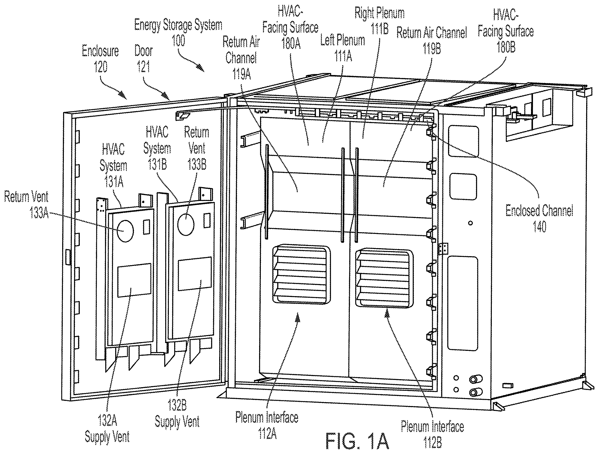
A is an isometric view of an energy storage system 100 that includes an enclosure 120 . As shown, enclosure 120 includes at least one door 121 . The enclosure 120 stores a plurality of battery racks 101 A-C. Each battery rack 101 A-C holds a respective plurality of battery modules 102 A-N, 103 A-N, 104 A-N. Each respective plurality of battery modules 102 A-N, 103 A-N, 104 A-N is shown as a separate stack of battery modules 102 x.
A-B show an example in which energy storage system 100 includes three battery racks 101 A-C and thus the respective plurality of battery modules 102 A-N, 103 A-N, 104 A-N are depicted as three separate stacks of battery modules 102 A-N, 103 A-N, 104 A-N held in a respective battery rack 101 A-C. In comparison, C shows an example in which energy storage system 100 includes six battery racks 101 A-F. Thus, the respective plurality of battery modules 102 A-N, 103 A-N, 104 A-N, 105 A-N, 106 A-N, 107 A-N are depicted as six separate stacks of battery modules 102 A-N, 103 A-N, 107 A-N held in a respective battery rack 101 A-F. Each plurality of battery modules 102 x, 103 x, . . . 107 x can include fewer or greater than fourteen battery modules, for example, five, fifteen, etc. For example, seventeen (17) battery modules 104 A-Q, 107 A-Q are actually shown in C .
Each battery module 102 A-N, 103 A-N, 107 A-N, . . . 107 A-N includes, for example, an array of prismatic, pouch, or cylindrical battery cells that are packaged together to increase voltage, amperage, or both. In some examples, each battery module 102 A-N, 103 A-N, . . . 107 A-N may include an electric vehicle battery pack, e.g., a collection of lithium-ion battery cells that are packaged together.
The enclosure further stores a plurality of plenums 111 A-B. Two plenums 111 A-B are shown in A . The plurality of plenums 111 x can include fewer or greater than two plenums 111 A-B, for example, one, three, four, or five plenums 111 x. Four plenums 111 A-D are shown in C .
The plurality of plenums 111 A-B includes a left plenum 111 A and a right plenum 111 B coupled together to form an enclosed channel 140 around the plurality of battery racks 101 A-C to direct air to the plurality of battery racks 101 A-C. Due to the formation of the enclosed channel 140 , the plurality of battery racks 101 A-C are not visible in A . For example, the left and right plenums 111 A-B are designed to be installed inside the enclosure 120 , in front of the three battery racks 101 A-C.
The enclosure 120 further stores a plurality of heating, ventilation, and air conditioning (HVAC) systems 131 A-B. HVAC systems 131 A-B are mounted on the at least one door 121 to supply air to the left plenum 111 A and the right plenum 111 B. HVAC systems 131 A-B supply cold or warm air to the plurality of plenums 111 A-B for cooling or heating of the battery modules 102 A-N held in battery racks 101 A-C. Each HVAC system 131 A-B includes a respective supply vent 132 A-B (e.g., to output cool air to battery modules 102 A-N) and a respective return vent 133 A-B (e.g., to remove warm air from battery modules 102 A-N). The respective supply vent 132 A-B and the respective return vent 133 A-B may be circular, rectangular, or have another shape to equally distribute the air and equalize the pressure. In the example, the supply vents 132 A-B are rectangular shaped and the return vents 133 A-B are circular shaped. The left plenum 111 A and the right plenum 111 B each include a plenum interface 112 A-B for coupling to the respective supply vent 132 A-B or the respective return vent 133 A-B. Although the HVAC systems 131 A-B each include a single respective supply vent 132 A-B and a single respective return vent 133 A-B in A , the number of supply vents 132 x and return vents 133 x may be greater than shown.
B is a top view of the plurality of battery racks 101 A-C stored in the enclosure 120 . As shown in B , the enclosure 120 stores the plurality of battery racks 101 A-C and many battery modules 102 A-N, 103 A-N, 104 A-N are held in the depicted battery racks 101 A-C. Three battery racks 101 A-C are shown, but fewer or greater than three battery racks 101 A-C, for example, one, two, four, five, etc. battery racks 101 x can be stored in the enclosure 120 . As further shown in B , each battery rack 101 A-C includes a respective upper surface 170 A-C. As shown, each battery rack 101 A-C has a mounted protruding tray 183 A-C and the protruding tray 183 A-C is visible at the front of the battery racks 101 A-C.
Each respective upper surface 170 A-C includes a plurality of rack openings 170 x. In the example of B , upper surface 170 A includes two rack openings 105 A-B, upper surface 170 B includes two rack openings 105 C-D, and upper surface 170 C includes two rack openings 105 E-F. For example, the rack openings 170 x are holes in the upper surfaces 170 A-C to attach plenums 111 A-B. Rack openings 170 A-B enable left plenum 111 A to couple to the battery rack 101 A and rack opening 170 C enables left plenum 111 A to couple to battery rack 101 B. Rack openings 170 D enables right plenum 111 B to couple to the battery rack 101 B and rack openings 170 E-F enable right plenum 111 B to couple to battery rack 101 C.
The plurality of battery modules 102 A-N, 103 A-N . . . 107 A-N can include power energy modules 108 A-N, power modules 109 A-N, or a combination of the energy modules 108 A-N and the power modules 109 A-N. In A-B , the battery modules 102 A-N, 103 A-N, 104 A-N include respective energy modules 108 A-N, which are capable of long duration charge and discharge (e.g., approximately 2 hours for full charge or discharge). In B , the front of the respective energy modules 108 A-N is the labeled area of protruding trays 183 A-C that stick out from the battery racks 101 A-C for connection to cables that are routed inside the enclosed channel 140 .
In C , the battery modules 102 A-N, 103 A-N, . . . 107 A-N include respective power modules 109 A-N, which are capable of short duration charge and discharge (approximately 30 minutes or 1 hour for full charge or discharge). Because the respective energy modules 108 A-N are larger in size (e.g., approximately double depth 193 of the two sets of power modules 109 A-N, 110 A-N), the enclosure includes a single door 121 in A-B . In contrast, the enclosure of C includes two doors 121 A-B because the two sets of power modules 109 A-N, 110 A-N are smaller in size (e.g., approximately half depth 193 ) of the energy modules 108 A-N.
Two HVAC systems 131 A-B are shown in A and are mounted on the door 121 . The number of HVAC systems 131 x can include fewer or greater than two HVAC systems 131 A-B, for example, one, three, four, five, etc. Each HVAC system 131 A-B can include an air handler (air handling unit) like that shown in A , a compressor (not shown), and a heater (e.g., gas furnace or heat pump). The air handler of each HVAC system 131 A-B includes a blower (not shown) and includes an evaporator coil. The compressor includes a condenser coil.
During air conditioning mode, warm return air is drawn in from a respective return air channel 119 A-B to a respective return vent 133 A-B. Return air channels 119 A-B are located outside the enclosed channel 140 formed by the plenums 111 A-B. Return air channels 119 A-B are shown as the inwards sloped surfaces formed on the HVAC-facing surface 180 A-B of the plenums 111 A-B. However, return air channels 119 A-B can be sloped (e.g., inwards or outwards), curved, flat or a combination thereof. Refrigerant-filled tubing circulates refrigerant between the evaporator coil and the condenser coil to cool the warm return air from the respective return vent 133 A-B intake and supply cold air from the respective supply vent 132 A-B output. This cold air supply is then directed out of the HVAC system 131 A-B to the battery racks 101 A-C via the plenum interface 112 A-B of the plenums 111 A-B.
In a cold climate during wintertime, HVAC systems 131 A-B run in a heating mode. During heating mode, cold return air is drawn in from a respective return air channel 119 A-B to a respective return vent 133 A-B and heated by the heater (e.g., gas furnace or heat pump) to warm the cold return air from the respective return vent 133 A-B intake and supply warm air from the respective supply vent 132 A-B output. This warm air supply is then directed out of the HVAC system 131 A-B to the battery racks 101 A-C via the plenum interface 112 A-B of the plenums 111 A-B.
C is an isometric view of the energy storage system 100 that includes an enclosure 120 . As shown, enclosure 120 includes a plurality of doors 121 A-B. In C , two HVAC systems 131 A-B are mounted on the first door 121 A and two HVAC systems 131 C-D (not shown) are mounted on the second door 131 B. As shown in B-C , each plenum 111 x has a plenum height 194 that approximately covers (e.g., encloses) an entire height 191 of the respective battery rack 101 x and at least a width 192 x of the respective battery rack 101 x. More specifically, each plenum 111 x includes: (i) a plenum height 194 that approximately covers one ( 1 ) battery rack 101 x in battery pack height 191 ; and (ii) a plenum width 195 that approximately covers one-and-a-half (1.5) battery racks 101 x in battery pack width 192 A-C.
The plurality of plenums 111 A-D include a first plenum set 111 A-B and a second plenum set 111 C-D. The first plenum set 111 A-B includes a first left plenum 111 A and a first right plenum 111 B. The second plenum set 111 C-D includes a second left plenum 111 C and a second right plenum 111 D. The enclosure 120 includes a first door 121 A and a second door 121 B. The respective plurality of battery modules 104 A-N, 107 A-N include a respective set of power modules 109 A-N, 110 A-N. The plurality of battery racks 101 A-F include a first set of battery racks 101 A-C facing the first door 121 A that hold a respective first set of power modules 109 A-N. The plurality of battery racks 101 A-F further include a second set of battery racks 101 D-F facing the second door 121 B that hold a respective second set of power modules 110 A-N. The first left plenum 111 A and the first right plenum 111 B form a first enclosed channel 140 A around the first set of battery racks 101 A-C to direct air to the first set of battery racks 101 A-C. The second left plenum 111 C and the second right plenum 111 D form a second enclosed channel 140 B around the second set of battery racks 101 E-F to direct air to the second set of battery racks 101 D-F.
In the example of C , the first door 121 A is a front door and the second door 121 B is a rear door. As shown, two HVAC systems 131 A-B are mounted on the first door 131 A (e.g., front door). Although not visible, another two HVAC systems 131 C-D are mounted on the second door 131 B (e.g., rear door). The three front-facing battery racks 101 A-C are coupled to the plenum interfaces 112 A-B of the first left plenum 111 A and the first right plenum 111 B. The three rear-facing battery racks 101 D-F are coupled to the plenum interfaces 112 C-D (not shown) of the second left plenum 111 C and the second right plenum 111 D.
D is a zoomed in perspective view of a plenum 111 x, e.g., configured as a right plenum 111 B, that shows a top surface 160 of the plenum 111 B for coupling to the upper surfaces 170 A-C of battery racks 101 A-C. In one example, the plenum 111 x can be made of aluminum 5052-H32 with a thickness of approximately 0.040 inches to keep the plenum 111 x lightweight. The plenum 111 x can be made of other types of metals, alloys, or other suitable thermally conductive materials. As shown, plenum 111 x has cutouts 162 A-D on the top surface 160 and upper right side 166 . The cutouts 162 A-D are added for the cable routing to the battery racks 101 A-C. Because the plenum 111 x is configured as right plenum 111 B, the right plenum 111 B encloses half of battery rack 101 B and the entirety of battery rack 101 C.
As shown, the top surface 160 of plenum 111 x includes a plurality of self-clinching studs 161 x. For example, the self-clinching studs 161 x are separately formed and then connected together with the plenum 111 A. For example, self-clinching studs 161 x are PEM® studs; however, the self-clinching studs 161 x can be formed integrally with the plenum 111 x. In the example, right plenum 111 B includes three self-clinching studs 161 D-F, which are shown in an encircled area. The top surface 160 of the right plenum 111 B has self-clinching studs 161 D-F for alignment and positioning over the rack openings 105 D-F shown in B . Although not shown, the left plenum 111 A similarly includes a plurality of self-clinching studs 161 A-C for alignment and positioning over the rack openings 105 A-C shown in B .
When the left plenum 111 A and the right plenum 111 B of B are coupled to battery racks 101 A-C, self-clinching studs 161 A-B of the left plenum 111 A are coupled to two of the rack openings 105 A-B of the battery rack 101 A. Self-clinching stud 161 C of the left plenum 111 A is coupled to the rack opening 105 C of the battery rack 101 B. Self-clinching stud 161 D of the right plenum 111 B is coupled to the other rack opening 105 D of the battery rack 101 B. Self-clinching studs 161 E-F of the right plenum 111 B are coupled to the rack openings 105 E-F of the battery rack 101 C.
is an isometric view of the battery racks 101 A-F of C . Generally, a respective battery rack 101 A-F includes a plurality of battery modules 102 A-N. Hence, the six battery racks 101 A-F are for holding respective battery modules 102 A-N, 103 A-N, . . . 107 A-N. As depicted, the two sets of power modules 109 A-N, 110 A-N of C are in a back-to-back configuration. In the back-to-back configuration, a front-facing battery rack 101 C holds a respective set of front-facing power modules 109 A-N and a rear-facing battery rack 101 F holds a respective set of rear-facing power modules 110 A-N.
As shown, the battery racks 101 A-F include a respective front-facing surface 215 A-F. The respective front-facing surface 215 A-F includes a respective plurality of tabs 210 A-G for coupling to the plenums 111 A-B. Existing battery rack designs may include tabs, but the tabs are typically for routing cables. But in , each of the battery racks 101 A-F have tabs 210 A-G on both sides of the front-facing surface 215 x to actually support the plenum(s) 111 x for installation purposes.
A is a front view of a plurality of plenums 111 A-B, for example a left plenum 111 A and a right plenum 111 B. B is an isometric view of the left plenum 111 A and the right plenum 111 B. C is a zoomed in view of the left plenum interface 112 A and the right plenum interface 112 B. The plurality of plenums 111 A-B are coupled together to form an enclosed channel 140 around the plurality of battery racks 101 A-C to direct air to the plurality of battery racks 101 A-C. As shown, the left plenum 111 B includes a plurality of handles 305 A-B and the right plenum 111 B includes a plurality of handles 305 C-D. More specifically, each plenum 111 A-B has two handles 305 A-B, 305 C-D, respectively, for ease of handling and installation. But the number of handles 305 x of the left plenum 111 A and the right plenum 111 B can be fewer or greater than the two handles 305 A-B, 305 C-D shown. For example, the plenum 111 x can include one, three, or four handles 305 x.
The left plenum 111 A and the right plenum 111 B are incorporated into the energy system 100 of A-D that includes a plurality of battery racks 101 A-C holding a plurality of battery modules 102 A. The energy storage system 100 further includes at least one heating, ventilation, and air conditioning (HVAC) system 131 x to supply air to the plurality of plenums 111 A-B. The at least one HVAC system 131 x includes a supply vent 132 x. The supply vent 132 x outputs cold air for cooling (during air conditioning mode) of the respective battery modules 102 A-N held by the battery racks 101 A-C. Alternatively, the supply vent 132 x outputs warm air for heating (during heating mode) of the battery modules 102 A-N. The supply vent 132 x is coupled a respective plenum 111 A-B. For example, if there is a single HVAC system 131 , then the single supply vent 132 is branched and coupled to both of the plenums 111 A-B. Alternatively, if there are two HVAC systems 131 A-B, then each supply vent 132 A-B is separated and coupled to a respective plenum 111 A-B.
In one example, the energy storage system 100 includes a plurality of heating, ventilation, and air conditioning (HVAC) systems 131 A-B to supply air to a respective plenum 111 A-B. Each HVAC system 131 A-B includes a respective supply vent 132 A-B and a respective return vent 133 A-B. The respective plenum 111 A-B includes a respective plenum interface 112 A-B for coupling to the respective supply vent 132 A-B or the respective return vent 133 A-B of a respective HVAC system 131 A-B. In a first example, the plenum interface 112 A-B is coupled to the respective supply vent 132 A-B of the respective HVAC system 131 A-B. The respective plenum 111 A-B includes a respective return air channel 119 A-B coupled to the respective return vent 133 A-B of the respective HVAC system 131 A-B. As shown, the left plenum 111 A includes a left return air channel 119 A and the right plenum 111 B includes a right return air channel 119 B. Left plenum 111 A includes an HVAC-facing surface 180 A in which the left return air channel 119 A is formed as two inwards sloped surfaces that intersect a flat surface. Right plenum 111 B includes another HVAC-facing surface 180 B in which the right return air channel 119 B is similarly formed.
Existing plenum designs typically require that the cross-sectional area of a plenum meet or exceed the cross-sectional area of the HVAC supply/return in order to maintain the speed of airflow in an enclosure environment. In contrast, as shown in A-D , the advantage of the proposed plenum 111 x design, is that the plenum 111 x can be open from one side (e.g., HVAC-facing surface 180 x), and covered from five sides (top surface 160 , inner side wall 414 , outer side wall 415 , and bottom surface 416 ), which allows the plenum 111 x dimensions to be much smaller and for the airflow to be directed straight out to the battery racks 101 A-C (e.g., heat source) via the enclosed channel 140 rather than going through several channels, which can result in a loss of air velocity. Moreover, the existing plenum designs require bolts, screws, or brackets to secure the existing plenums in place. In contrast, the design of plenum 111 x enables easier installation and removal of the plenum 111 x. During installation, the plenum 111 x can be dropped in place by an installer (e.g., single person) using the built-in handles 305 A-B and then coupled to the battery racks 101 A-C via the side slots 408 A-G and self-clinching studs 161 x on the top surface 160 . During removal, the plenum 111 x can be lifted out of place by the installer using the built-in handles 305 A-B. Finally, as described in A-B , the plenum 111 x design is adjustable to facilitate the depth adjustment 615 A-B to the HVAC system 131 x via the plenum interface 112 x.
A is a front view of a single plenum 111 x, e.g., configured as a right plenum 111 B. B is an isometric view of the plenum 111 x of A . As shown, the plenum 111 x includes a plenum interface 112 x for coupling to a supply vent 132 x of the HVAC system 131 x like that of A-C . Plenum 111 x also includes a return air channel 119 x for coupling to the return vent 133 x like that of A-C . In the arrangement of A-B , the plenum 111 x causes a front to rear air flow through the battery racks 101 A-C.
As shown, plenum 111 x includes a plenum body 406 , handles 305 A-B, plenum side plate 407 , inner side wall 414 , outer side wall 415 , and bottom surface 416 . Plenum 111 x can be assembled using stainless steel rivets, for example. The plenum 111 x has side slots 408 A-G on the sides (e.g., formed in outer side wall 415 ), and the side slots 408 A-G act as guides for positioning of the plenum 111 x on the battery racks 101 A-C. As depicted in , the respective battery rack 101 A-F includes a plurality of tabs 210 A-G. The respective plenum 111 A-B is coupled to the respective battery rack 101 A-C via the plurality of tabs 210 A-G. For example, respective side slots 408 A-G engage respective tabs 210 A-G on front-facing surfaces 215 A-C of the battery racks 101 A-C to secure plenum 111 x in place. The side slots 408 A-G of the plenum 111 x and the respective tabs 210 A-G on the battery racks 101 A-C can be located on different surfaces to secure the plenum 111 x in place.
B further depicts that the plenum 111 x includes a top surface 160 and an upper right side 166 (e.g., plenum side plate 407 ) that include cutouts 162 A-D like that shown in D . Energy storage system 100 includes a plurality of cables for electrical connection to the respective battery rack 101 A-C. The respective plenum 111 A-B includes a top surface 160 having cutouts 162 A-D for routing of the plurality of cables to the plurality of battery racks 101 A-C.
C-D are views of a plenum 111 x showing the geometry, for example, dimensions in inches and degree measurements of the various structures of the plenum 111 x. As shown, the plenum 111 x includes an inner side wall 414 and an outer side wall 415 . For example, the outer side wall includes 415 includes the plenum side plate 407 and the side slots 408 A-G. In the energy storage system 100 , where the plurality of plenums 111 A-B includes a left plenum 111 A and a right plenum 111 B, each plenum 111 A-B includes a respective inner side wall 414 A-B and a respective outer side wall 415 A-B. The left plenum 111 A and the right plenum 111 B intersect at the respective inner side wall 414 A-B. The respective outer side wall 415 A-B covers a greater depth 193 of the respective battery rack 101 A-C compared to the respective inner side wall 414 A-B (e.g., inner side wall 414 B is not as deep as outer side wall 415 B).
is a front view of a single plenum 111 x, in which the single plenum 111 x includes a plenum interface 112 x coupled to a supply air channel 532 x of the HVAC system 131 x. In other words, the plenum interface 112 x is now relocated from the supply vent 132 x to the return vent 133 x, which causes a rear to front air flow through the battery racks 101 A-C. The plenum 111 x configured for the rear to front air flow configuration includes handles 305 A-B, which are not depicted. Although shown as having a rectangular shape, the plenum interface 112 x may be circular or any other shape that is suitable for coupling to the return vent 133 x of the HVAC system 131 x. Plenum 111 x also now includes a supply air channel 519 x, which is formed in the HVAC-facing surface 180 x as a flat valley below the plenum interface 112 x. For example, in an energy storage system 100 that includes a plurality of HVAC systems 131 A-B, the respective plenum interface 112 A-B is coupled to the respective return vent 133 A-B of the respective HVAC system 131 A-B. The respective plenum 111 A-B includes a respective supply air channel 519 A-B coupled to the respective supply vent 132 A-B of the respective HVAC system 131 A-B.
Either: (i) the supply vent 132 x is coupled to the plenum interface 112 x (as in A-B ), or (ii) the return vent 133 x is coupled to the plenum interface 112 x (as in ), but not both (i) and (ii). Ducting both the supply vent 132 x and the return vent 133 x to separate plenum interfaces 112 x would create a short-circuit inside the enclosed channel 140 , which prevents proper air flow of the supply air and return air.
A is a zoomed in isometric view of the plenum interface 112 A of the left plenum 111 A and the plenum interface 112 B of the right plenum 111 B before a depth adjustment 615 A-B. B is a zoomed in isometric view of the plenum interface 112 A of the left plenum 111 A and the plenum interface 112 B of the right plenum 111 B during the depth adjustment 615 A-B. C are views of a plenum interface 112 x showing the geometry, for example, dimensions in inches of the various structures of the plenum interface 112 x. As shown, the respective plenum interface 112 A-B includes a respective slider 610 A-B for a depth adjustment 615 A-B of the respective plenum 111 A-B to the respective HVAC system 131 A-B. The respective slider 610 A-B can be formed of two sheet metal pieces (e.g., L-shaped brackets 611 A-B) that are spot welded together, for example.
The respective plenum interface 112 A-B includes a respective gasket 620 A-B around the respective slider 610 A-B to form a compression seal 625 A-B between the respective slider 610 A-B and the respective supply vent 132 A-B or the respective return vent 133 A-B. As shown, the respective gasket 620 A-B sits on an outer portion of the respective slider 610 A-B. The respective gasket 620 A-B can be a push on seal that is water and weather resistant. The respective gasket 620 A-B can be formed of fluoroelastomer, ethylene propylene diene rubber (EPDM), styrene butadiene rubber (SBR), or other thermoset or thermoplastic polymers. The respective gasket 620 A-B can include corner bulbs 670 x (e.g., two or four) formed of EPDM foam with a temperature range of −29° to 65° C. that compress between the two L-shaped brackets 611 A-B that form the respective slider 610 A-B. The respective gasket 620 A-B compresses when the door 121 of the enclosure 120 is closed to provide a sealing mechanism between the respective plenum 111 A-B and the respective HVAC system 131 A-B.
In the example of A-C , the respective plenum interface 112 A-B is coupled to the respective supply vent 132 A-B of the respective HVAC system 131 A-B. The respective plenum interface 112 A-B includes a plurality of deflector plates 640 A-D to divert air flow to uniformly distribute air from the respective supply vent 132 A-B to the plurality of battery racks 101 A-C. More specifically, deflector plates 640 A-D divert the air flow towards/across the battery racks 101 A-C to achieve uniform distribution of air to the battery modules 101 A-N, 102 A-N, 103 A-N.
The respective plenum interface 112 A-B includes four deflector plates 640 A-D in A-B . Each of the deflector plates 640 A-D can be adjusted manually by an installer to optimize air flow distribution. The respective plenum interface 112 A-B can include fewer or greater than four deflector plates 640 A-D, for example, one, two, three, four, or five deflector plates 640 x.
As further shown, the respective slider 610 A-B includes a plurality of slider sides 650 A-D (e.g. four), numbered consecutively in a clockwise direction as a top slider side 650 A, a right slider side 650 B, a bottom slider side 650 C, and a left slider side 650 D. Each slider side 650 A-D of the respective slider 610 A-B includes a respective slider slot 660 A-D (e.g., four) for the depth adjustment 615 A-B of the respective plenum 111 A-B to the respective supply vent 132 A-B or the respective return vent 133 A-B. As shown, each of the four slider slots 660 A-D have an oblong shape. Although shown as having an oblong shape, the slider slots 660 A-D can be various shapes. The respective slider 610 A-B further includes a respective fastener 661 A-D (e.g., four class 8.8 steel flanged hex head screws are used) for the depth adjustment 615 x of a slider side 650 A-D. During the depth adjustment 615 x, an installer utilizes a tool, such as screwdriver, to loosen the respective fastener 661 A-D to free the respective slider side 650 A-D and allow movement of the respective slider side 650 A-D. When all fasteners 661 A-D are sufficiently loosened, the installer pulls the respective slider 610 A-B out of the respective plenum 111 A-B or pushes the respective slider 610 A-B into the respective plenum 111 A-B to adjust a respective distance 680 A-B of the respective slider 610 A-B to the respective supply vent 132 A-B or the respective return vent 133 A-B. Once the respective distance is correctly set, the installer affixes the respective slider 610 A-B to the respective supply vent 132 A-B or the respective return vent 133 A-B by tightening all fasteners 661 A-D. The leeway of the respective distance 680 A-B during the depth adjustment 615 can be several inches (e.g., 2-3 inches) or feet (1-3 feet) or more.
Sliders 610 A-B can have a different shape, e.g., a continuous shape, such as a circle or oval; or the sliders 610 A-B can be a discontinuous shape, such as a polyhedron, including a triangle, pentagon, etc. Hence, although the sliders 610 A-B are shown as a rectangular shape that includes four sides 650 A-D, the sliders 610 A-B can include few or greater than four sides 650 A-D. For example, the sliders 610 A-B can have one side 650 with a continuous circumference or perimeter as in a circle or oval; or the sliders 610 A-B can have two, three, five, or more sides 650 x as in a polyhedron.
D depicts views of a flange assembly 695 x to couple the plenum interface 112 x to a supply vent 132 x or a return vent 133 x. For each respective plenum 111 A-B, the energy storage system 100 includes a respective flange assembly 695 A-B that couples the respective plenum interface 112 A-B to the respective supply vent 132 A-B or the respective return vent 133 A-B. Plenums 111 A-B can integrate the flange assemblies 695 A-B with the plenum interfaces 112 A-B or the flange assemblies 695 A-B can be provided separately and then coupled together.
The flange assembly 695 x includes a plurality of flanges 696 A-D (e.g., L-shaped sheet metal pieces). In the example, the flange assembly 695 x includes four flanges 696 A-D. The flange assembly 696 x further includes a respective fixing mechanism 697 A-D (e.g., an M6 self-clinching nut) to attach each of the flanges 696 A-D around the slider 112 x. The number of flanges 696 x can vary depending on the shape (e.g., polygon shape) of the plenum interface 112 x and the supply vent 132 x or the return vent 133 x. Alternatively, the flange assembly 695 x can be a continuous circular or oval shape formed of a single piece of flange 696 with one or more fixing mechanisms 697 x to attach a circumference or perimeter of the flange 696 to the supply event 132 x or the return vent 133 x.
In A -D, an energy storage system 100 includes an enclosure 120 around the plurality of battery racks 101 A-C and the plurality of plenums 111 A-B. Enclosure 120 includes a door 121 and the plurality of HVAC systems 131 A-B are mounted on the door 121 . When the door 131 is closed, a respective gasket 620 A-B around a respective slider 610 A-B forms a respective compression seal 625 A-B between the respective slider 610 A-B and the respective supply vent 132 A-B or the respective return vent 133 A-B.
depicts views of the plenum side plate 407 showing the geometry, for example, dimensions in inches of the various structures of the plenum side plate 407 . The plenum side plate 407 is placed on the upper right side 166 of the plenum 111 x to accommodate the protruding tray 183 x. As noted earlier, the protruding tray 183 x is mounted to the front of the battery rack 101 x (see B for the protruding tray 183 x). Cables that connect to the battery racks 101 x are routed through the plenum side plate 407 . For example, the cables can provide electrical connection for the battery modules 102 x held in the battery racks 101 x, as well as input/output (I/O) signals to the control processing logic for management of the battery racks
A is a zoomed in isometric view of a plenum interface 112 x showing a plurality of deflector plates 640 A-D (e.g., four) of the slider 610 x, as well as the gasket 610 x. As shown, the slider 610 x includes a plurality of slider sides 650 A-D (e.g., four), which are labeled consecutively in a clockwise direction as top slider side 650 A, a right slider side 650 B, a bottom slider side 650 C, and a left slider side 650 D. Each slider side 650 A-D includes a respective slider slot 660 A-D. The plurality of deflector plates 640 A-D are coupled to the right slider side 650 B and the left slider side 650 D. Each of the deflector plates 640 A-D are coupled to the right slider side 650 B by a respective right rivet 811 A-D. Although not visible in A , each of the deflector plates 640 A-D are coupled to the left slider side 650 B by a respective left rivet 806 A-D.
B depicts views of the deflector plate 640 x showing the geometry, for example, dimensions in inches of the various structures of the deflector plate 640 x. The deflector plates 640 A-D can be formed of 0.040 inch thick aluminum 5052-H32, for example.
Each deflector plate 640 x is riveted on two opposing sides, for example, and can rotate along the axis of the rivet 806 x, 811 x. As shown, each deflector plate 640 A-D is riveted on the left deflector side 805 and the right deflector side 810 . The left deflector side 805 and the left slider side 650 D both hold a respective left rivet 806 A-D. The right deflector side 810 and the right slider side 650 B both hold a respective right rivet 811 A-D. Consequently, a respective deflector plate 640 A-D can rotate along an axis of the respective left rivet 806 A-D and the respective right rivet 811 A-D. During installation, the installer rotates the deflector plates 640 A-D to optimize air flow distribution to the battery modules 102 x held in the battery racks 101 x.
The scope of protection is limited solely by the claims that now follow. That scope is intended and should be interpreted to be as broad as is consistent with the ordinary meaning of the language that is used in the claims when interpreted in light of this specification and the prosecution history that follows and to encompass all structural and functional equivalents. Notwithstanding, none of the claims are intended to embrace subject matter that fails to satisfy the requirement of Sections 101, 102, or 103 of the Patent Act, nor should they be interpreted in such a way. Any unintended embracement of such subject matter is hereby disclaimed.
Except as stated immediately above, nothing that has been stated or illustrated is intended or should be interpreted to cause a dedication of any component, step, feature, object, benefit, advantage, or equivalent to the public, regardless of whether it is or is not recited in the claims.
It will be understood that the terms and expressions used herein have the ordinary meaning as is accorded to such terms and expressions with respect to their corresponding respective areas of inquiry and study except where specific meanings have otherwise been set forth herein. Relational terms such as first and second and the like may be used solely to distinguish one entity or action from another without necessarily requiring or implying any actual such relationship or order between such entities or actions. The terms “comprises,” “comprising,” “includes,” “including,” or any other variation thereof, are intended to cover a non-exclusive inclusion, such that a process, method, article, or apparatus that comprises or includes a list of elements or steps does not include only those elements or steps but may include other elements or steps not expressly listed or inherent to such process, method, article, or apparatus. An element preceded by “a” or “an” does not, without further constraints, preclude the existence of additional identical elements in the process, method, article, or apparatus that comprises the element.
In addition, in the foregoing Detailed Description, it can be seen that various features are grouped together in various examples for the purpose of streamlining the disclosure. This method of disclosure is not to be interpreted as reflecting an intention that the claimed examples require more features than are expressly recited in each claim. Rather, as the following claims reflect, the subject matter to be protected lies in less than all features of any single disclosed example. Thus the following claims are hereby incorporated into the Detailed Description, with each claim standing on its own as a separately claimed subject matter.
While the foregoing has described what are considered to be the best mode and/or other examples, it is understood that various modifications may be made therein and that the subject matter disclosed herein may be implemented in various forms and examples, and that they may be applied in numerous applications, only some of which have been described herein. It is intended by the following claims to claim any and all modifications and variations that fall within the true scope of the present concepts.
Figures (20)
Citations
This patent cites (16)
- US2007/0002536
- US2010/0059270
- US2012/0086399
- US2014/0210419
- US2015/0003009
- US2015/0194707
- US2015/0372517
- US2017/0077467
- US2017/0294633
- US2018/0142935
- US2020/0079241
- US2020/0144845
- US2021/0281081
- US2017044830
- US2018128783
- US2018222858