Abstract
According to one embodiment, a sensor system includes a pipe and a sensor. The sensor is configured to detect a detection target substance in the pipe. The sensor includes a base, a first detection part, and a second detection part. The base includes a first base region and a second base region. The first detection part includes a first support part, a first connection part, and a first detection element. The second detection art includes a second support part, a second connection part, and a second detection element.
Claims (20)
1 . A sensor system, comprising: a pipe; and at least one sensor configured to detect a detection target substance in the pipe, the at least one sensor including: a base, a first detection part, and a second detection part, the base including a first base region and a second base region, the first detection part including a first support part, a first connection part, and a first detection element, a position of the first detection part with respect to the first base region being fixed, the first connection part being supported by the first support part, the first connection part supporting the first detection element, a first gap being provided between the first base region and the first detection element, the first detection part having a first area of the first detection element, a first connection part length of the first connection part, a first connection part width of the first connection part, a first connection part thickness of the first connection part, a first connection part material of the first connection part, and a first distance, the first distance being a distance between the first base region and the first detection element, the second detection part including a second support part, a second connection part, and a second detection element, a position of the second support part with respect to the second base region being fixed, the second connection part being supported by the second support part, the second connection part supporting the second detection element, a second gap being provided between the second base region and the second detection element, and the second detection part having at least one of a second area different from the first area of the second detection element, a second connection part length different from the first connection part length of the second connection part, a second connection part width different from the first connection part width of the second connection part, a second connection part thickness different from the first connection part thickness of the first connection part thickness, a second connection part material different from the first connection part material of the second connection part, or a second distance different from the first distance, the second distance being a distance between the second base region and the second detection element.
Show 19 dependent claims
2 . The system according to claim 1 , wherein the second base region is continuous with the first base region.
3 . The system according to claim 1 , wherein the second base region is separate from the first base region.
4 . The system according to claim 1 , wherein the detection target substance includes a first substance and a second substance different from the first substance.
5 . The system according to claim 4 , wherein the first substance includes one selected from a group consisting of carbon monoxide, carbon dioxide, and hydrogen, and the second substance includes another one selected from the group consisting of carbon monoxide, carbon dioxide, and hydrogen.
6 . The system according to claim 4 , wherein The detection target substance is a gas.
7 . The system according to claim 4 , wherein the first detection element includes a first resistance member, a first conductive member, and a first insulating member, at least a part of the first insulating member being between the first resistance member and the first conductive member, and the second detection element includes a second resistance member, a second conductive member, and a second insulating member, at least a part of the second insulating member being between the second resistance member and the second conductive member.
8 . The system according to claim 7 , wherein the at least one sensor further includes a controller, the controller is configured to be electrically connected to the first resistance member, the first conductive member, the second resistance member, and the second conductive member, the controller is configured to perform a first operation, the controller supplies a first current to the first conductive member to raise a temperature of the first detection element in the first operation, the controller supplies a second current to the second conductive member to raise a temperature of the second detection element in the first operation, the controller derives a first value corresponding to a first electrical resistance of the first resistance member in the first operation, the controller derives a second value corresponding to a second electrical resistance of the second resistance member in the first operation, and the controller is configured to output a detection signal including a first detection value and a second detection value based on the first value and the second value in the first operation, the first detection value corresponding to a concentration of the first substance included in a space around the first detection element and the second detection element, the second detection value corresponding to a concentration of the second substance included in the space.
9 . The system according to claim 1 , wherein the at least one sensor includes a housing, at least a part of the first detection part and at least a part of the second detection part are provided between the base and the housing, the housing includes a first inflow port and a first outflow port, the target detection substance is configured to flow in from the first inflow port between a part of the housing and the first detection part and between a part of the housing and the second detection part, and the detection target substance is configured to exit through the first outflow port.
10 . The system according to claim 1 , wherein the pipe includes a first flow path and a second flow path branched off from the first flow path, and the at least one sensor is provided in one of the first flow path and the second flow path.
11 . The system according to claim 1 , wherein the pipe includes: a first flow path including a first portion and a second portion, and a second flow path branched off from the first portion and connected to the second portion, and the at least one sensor is provided in one of the first flow path and the second flow path.
12 . The system according to claim 1 , wherein the at least one sensor further includes a plurality of sensors, and at least one of the plurality of sensors is provided in the pipe.
13 . The system according to claim 1 , wherein the at least one sensor further includes a plurality of sensors, the pipe includes a first flow path and a second flow path branched off from the first flow path, and at least two of the plurality of sensors are provided in the second flow path.
14 . The system according to claim 1 , wherein the at least one sensor further includes a plurality of sensors, the pipe includes: a first flow path including a first portion, a second portion, a third portion, and a fourth portion, a second flow path branched off from the first portion and connected to the second portion, and a third flow path branched off from the third portion and connected to the fourth portion, at least one of the plurality of sensors is provided in the second flow path, and another one of the plurality of sensors is provided in the third flow path.
15 . The system according to claim 1 , wherein the pipe further includes a plurality of pipes, the at least one sensor further includes a plurality of sensors, one of the plurality of sensors is configured to detect the detection target substance in one of the plurality of pipes, and another one of the plurality of sensors is configured to detect the detection target substance in another one of the plurality of pipes.
16 . The system according to claim 15 , wherein the detection target substance in one of the plurality of pipes includes a first substance, and a second substance different from the first substance, the first substance includes one selected from a group consisting of carbon monoxide, carbon dioxide, and hydrogen, the second substance includes an other one selected from the group consisting of carbon monoxide, carbon dioxide, and hydrogen, the detection target substance in the other one of the plurality of pipes includes a third substance, and a fourth substance different from the third substance, the third substance includes one selected from a group consisting of oxygen and carbon dioxide, and the fourth substance includes an other one selected from the group consisting of oxygen and carbon dioxide.
17 . A gas system, comprising: the sensor system according to claim 1 ; and a gas supplier configured to supply a gas including the detection target substance to the pipe.
18 . The gas system according to claim 17 , wherein the gas supplier is configured to convert at least a part of a supply gas supplied to the gas supplier to at least a part of the gas including the detection target substance.
19 . The gas system according to claim 17 , wherein the gas supplier is configured to convert at least a part of a raw material supplied to the gas supplier to at least a part of the gas including the detection target substance.
20 . The gas system according to claim 17 , wherein the gas supplier is configured to generate the gas including the detection target substance from a raw material.
Full Description
Show full text →
CROSS-REFERENCE TO RELATED APPLICATIONS
This application is based upon and claims the benefit of priority from Japanese Patent Application No. 2022-116426, filed on Jul. 21, 2022; the entire contents of which are incorporated herein by reference.
FIELD
Embodiments described herein relate generally to a sensor system and a gas system.
BACKGROUND
For example, there are sensors using MEMS (Micro Electro Mechanical Systems) elements. The sensor is applied for a gas system such as a gas conversion system. It is desired to improve the characteristics of the sensor.
BRIEF DESCRIPTION OF THE DRAWINGS
is a schematic view illustrating a sensor system according to a first embodiment;
is a schematic view illustrating a part of the sensor system according to the first embodiment;
is a schematic view illustrating a part of the sensor system according to the first embodiment;
is a schematic view illustrating a part of the sensor system according to the first embodiment;
A and 5 B are schematic views illustrating alternative sensor systems according to the first embodiment;
A and 6 B are schematic views illustrating alternative sensor systems according to the first embodiment;
A to 7 D are schematic views illustrating alternative sensor systems according to the first embodiment;
A to 8 C are schematic views illustrating alternative sensor systems according to the first embodiment;
is a schematic cross-sectional view illustrating a part of a sensor system according to the first embodiment;
is a schematic view illustrating a part of a sensor system according to the first embodiment;
is a plan view illustrating the part of the sensor system illustrated in ;
is another plan view illustrating the part of the sensor system illustrated in ;
is a schematic cross-sectional view illustrating a part of a sensor system according to the first embodiment;
is a schematic cross-sectional view illustrating a part of a sensor system according to the first embodiment;
is a schematic view illustrating a part of a sensor system according to the first embodiment;
A and 16 B are graphs illustrating characteristics in a sensor system according to the first embodiment;
A and 17 B are graphs illustrating characteristics in a sensor system according to the first embodiment;
is a schematic cross-sectional view illustrating a part of a sensor system according to the first embodiment;
is a schematic cross-sectional view illustrating a part of a sensor system according to the first embodiment;
is a schematic cross-sectional view illustrating a part of a sensor system according to the first embodiment;
is a schematic cross-sectional view illustrating a part of a sensor system according to the first embodiment;
is a schematic cross-sectional view illustrating a part of a sensor system according to the first embodiment;
A to 23 C are schematic cross-sectional views each illustrating a part of a sensor system according to the first embodiment;
is a schematic cross-sectional view illustrating a part of a sensor system according to the first embodiment;
is a schematic cross-sectional view illustrating a part of a sensor system according to the first embodiment;
A and 26 B are schematic cross-sectional views each illustrating a part of a sensor system according to the first embodiment;
A and 27 B are schematic cross-sectional views each illustrating a part of a sensor system according to the first embodiment;
A and 28 B are schematic cross-sectional views each illustrating a part of a sensor system according to the first embodiment;
A and 29 B are schematic cross-sectional views each illustrating a part of a sensor system according to the first embodiment; and
A to 30 C are schematic views illustrating various gas systems according to a second embodiment.
DETAILED DESCRIPTION
According to one embodiment, a sensor system includes a pipe, and at least one sensor configured to detect a detection target substance in the pipe. The at least one sensor includes a base, a first detection part, and a second detection part. The base includes a first base region and a second base region. The first detection part includes a first support part, a first connection part, and a first detection element. A position of the first detection part with respect to the first base region is fixed. The first connection part is supported by the first support part. The first connection part supports the first detection element. A first gap is provided between the first base region and the first detection element. The first detection part has a first area of the first detection element, a first connection part length of the first connection part, a first connection part width of the first connection part, a first connection part thickness of the first connection part, a first connection part material of the first connection part, and a first distance. The first distance is a distance between the first base region and the first detection element. The second detection part includes a second support part, a second connection part, and a second detection element. A position of the second support part with respect to the second base region is fixed. The second connection part is supported by the second support part. The second connection part supports the second detection element. A second gap is provided between the second base region and the second detection element. The second detection part has at least one of a second area different from the first area of the second detection element, a second connection part length different from the first connection part length of the second connection part, a second connection part width different from the first connection part width of the second connection part, a second connection part thickness different from the first connection part thickness of the first connection part thickness, a second connection part material different from the first connection part material of the second connection part, or a second distance different from the first distance. The second distance is a distance between the second base region and the second detection element.
Various embodiments are described below with reference to the accompanying drawings.
The drawings are schematic and conceptual; and the relationships between the thickness and width of portions, the proportions of sizes among portions, etc., are not necessarily the same as the actual values. The dimensions and proportions may be illustrated differently among drawings, even for identical portions.
In the specification and drawings, components similar to those described previously or illustrated in an antecedent drawing are marked with like reference numerals, and a detailed description is omitted as appropriate.
First Embodiment
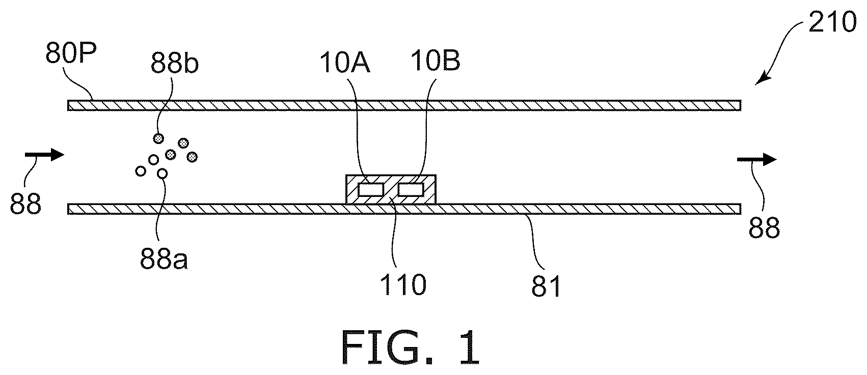
is a schematic view illustrating a sensor system according to a first embodiment.
As shown in , a sensor system 210 according to an embodiment includes a pipe 80 P and at least one sensor 110 .
The at least one sensor 110 can detect the detection target substance 88 in the pipe 80 P. For example, the detection target substance 88 is a gas. The sensor 110 detects the detection target substance 88 flowing through the pipe 80 P. The arrows in the drawings represent the detection target substance 88 and its flow direction through the pipe 80 P.
In the embodiment, the sensor 110 includes multiple detection parts (e.g., first detection part 10 A and second detection part 10 B, etc.). By processing detection signals obtained from the multiple detection parts, the detection target substance 88 can be detected with higher accuracy.
For example, the detection target substance 88 includes a first substance 88 a and a second substance 88 b . The second substance 88 b is different than the first substance 88 a.
At least two of the multiple detection parts have different detection characteristics. Detection signals (detection results) from detection parts having different detection characteristics are processed. For example, concentrations of different types of multiple substances can be detected with high accuracy. A sensor system capable of improving characteristics can be provided.
Hereinafter, examples of sensors (such as the sensor 110 ) according to the embodiment will be described.
to 4 are schematic views illustrating a part of the sensor system according to the first embodiment.
is a cross-sectional view taken along the line II-II′ of . are plan views. As shown in to 4 , the sensor 110 according to the embodiment includes a base 41 , the first detection part 10 A and the second detection part 10 B.
As shown in , the base 41 includes a first base region 41 a and a second base region 41 b . In this example, the base 41 includes a substrate 41 s and an insulating film 41 i . The substrate 41 s may be, for example, a semiconductor substrate (for example, a silicon substrate). The substrate 41 s may include, for example, a semiconductor circuit or the like. The substrate 41 s may include connection members such as via electrodes.
In this example, the second base region 41 b is continuous with the first base region 41 a . For example, multiple detection parts are provided on one semiconductor substrate. As will be described later, the second base region 41 b may be separated from the first base region 41 a.
A direction from the first base region 41 a to the second base region 41 b is along an upper surface of the base 41 , for example.
As shown in , the first detection part 10 A includes a first detection element 11 E. The first detection element 11 E includes a first resistance member 11 , a first conductive member 21 and a first insulating member 18 A. At least a part of the first insulating member 18 A is between the first resistance member 11 and the first conductive member 21 . In this example, the first insulating member 18 A surrounds a first resistance member 11 . The first insulating member 18 A surrounds the first conductive member 21 . In this example, the first conductive member 21 is between the base 41 and the first resistance member 11 . In the embodiment, the first resistance member 11 may be between the base 41 and the first conductive member 21 . A first gap g 1 is provided between the first base region 41 a and the first detection element 11 E.
illustrates a planar pattern of the first conductive member 21 and the second conductive member 22 . illustrates a planar pattern of the first resistance member 11 and the second resistance member 12 .
As shown in , in this example, the first detection element 11 E (the portion including the first resistance member 11 , the first conductive member 21 and the first insulating member 18 A) is octagonal. The planar shape of the first detection element 11 E is arbitrary. The first detection element 11 E has a first area S 1 . The first area S 1 is an area of the first detection element 11 E on a plane crossing a first direction from the first base region 41 a to the first detection element 11 E.
As shown in , the first direction is defined as a Z-axis direction. A direction perpendicular to the Z-axis direction is defined as an X-axis direction. A direction perpendicular to the Z-axis direction and the X-axis direction is defined as a Y-axis direction. A plane crossing the first direction is, for example, an X-Y plane.
As shown in , the second detection part 10 B includes a second detection element 12 E. The second detection element 12 E includes a second resistance member 12 , a second conductive member 22 and a second insulating member 18 B. At least a part of the second insulating member 18 B is between the second resistance member 12 and the second conductive member 22 . In this example, the second insulating member 18 B surrounds the second resistance member 12 . The second insulating member 18 B surrounds the second conductive member 22 . In this example, the second conductive member 22 is between the base 41 and the second resistance member 12 . In the embodiment, the second resistance member 12 may be between the base 41 and the second conductive member 22 . A second gap g 2 is provided between the second base region 41 b and the second detection element 12 E.
As shown in , in this example, the second detection element 12 E (the portion including the second resistance member 12 , the second conductive member 22 and the second insulating member 18 B) is octagonal. The planar shape of the second detection element 12 E is arbitrary. The second detection element 12 E has a second area S 2 . The second area S 2 is an area of the second detection element 12 E on the plane (the plane crossing the first direction). The second area S 2 is smaller than the first area S 1 .
As shown in , a controller 70 may be provided. The controller 70 can be electrically connected to the first resistance member 11 , the first conductive member 21 , the second resistance member 12 and the second conductive member 22 . For example, the controller 70 supplies a first current i 1 to the first conductive member 21 to raise a temperature of the first detection element 11 E. The controller 70 supplies a second current i 2 to the second conductive member 22 to raise a temperature of the second detection element 12 E.
The temperature of these detection elements rises due to Joule heat due to the supplied current. The heat amount in these detection elements changes via substances (such as gases) included in the space around these detection elements. The degree of heat amount change depends on the thermal conductivity of the substances included in the surrounding space. Temperatures of these detection elements are detected by resistance members. By detecting the temperature of these detection elements, the presence and concentration of substances included in the surrounding space can be detected. A detection signal 70 s including the detection result is output from the controller 70 .
In the embodiment, for example, areas are different between the first detection element 11 E and the second detection element 12 E. Due to the difference in area, these detection elements have different heat amount change characteristics (for example, heat dissipation characteristics). Due to the difference in area, the temperature change characteristics of these detection elements are different from each other. By using the difference in characteristics of temperature change, for example, it is possible to detect the substance to be detected with higher accuracy. According to the embodiment, it is possible to provide a sensor whose characteristics can be improved.
For example, the space around these detection elements may include multiple substances of different types. For example, the space may include carbon monoxide, carbon dioxide (e.g., first substance), and hydrogen (e.g., second substance). In the first reference example using one detection element, the temperature of the detection element is affected by both the thermal conductivity of multiple substances of different types and the concentration of these substances. Therefore, in the first reference example, it is difficult to detect multiple different types of substances (first substance, second substance, etc.).
In a second reference example, a method is conceivable in which one detection element is used, the detection element is heated to multiple temperatures, and the temperature (degree of heat dissipation) of the detection element is detected at multiple temperatures. In the second reference example, detection accuracy is not sufficient when detecting multiple types of substances using multiple temperature measurement results of the detection element. In the second reference example, since only one detection element is used and only one type of heat dissipation characteristic is used, the accuracy is insufficient. Furthermore, in the second reference example, since the temperature needs to be raised multiple times, the measurement time is long. In the second reference example, the control circuit is complicated.
In the embodiment, the multiple detection elements with different heat dissipation characteristics are used. By using the temperature change characteristics of the detection elements with different heat dissipation characteristics, it is possible to separate the influence of the thermal conductivity of multiple substances of different types and the concentrations of these substances. For example, for each of the multiple detection elements, information about the relationship between the concentration of each of multiple substances of different types and the temperature (or the value corresponding to the temperature) is acquired in advance. By using this information and the measured values (multiple values) of the temperature (or the value corresponding to the temperature) obtained from these detection elements, the concentration of each of multiple substances of different types can be detected with high accuracy. For example, by solving simultaneous equations, it is possible to detect concentrations of different substances with high accuracy. In the embodiment, the measurement time is short because the measurement is performed with multiple detection elements.
An example of a method of processing in detection will be described later in the embodiment.
As described above, in the embodiment, the second area S 2 of the second detection element 12 E is smaller than the first area S 1 of the first detection element 11 E. In the embodiment, the relationship between these areas may be reversed.
As shown in , the first detection element 11 E has a first length L 1 in a direction (e.g., second direction) crossing the first direction (Z-axis direction). The second direction is one direction along the X-Y plane. The second direction may be, for example, the X-axis direction. The second detection element 12 E has a second length L 2 in a direction (e.g., second direction) crossing the first direction (Z-axis direction). In this example, the second length L 2 is shorter than the first length L 1 . A difference in area is obtained.
As shown in to 4 , for example, the first detection part 10 A may further include a first support part 31 S and a first connection part 31 C. The first support part 31 S is fixed to the base 41 . The first connection part 31 C is supported by the first support part 31 S and supports the first detection element 11 E. A gap is provided between the first base region 41 a and the first connection part 31 C. The first connection part 31 C has, for example, a spring structure. The first detection part 10 A may have a cantilever structure.
The second detection part 10 B may further include a second support part 32 S and a second connection part 32 C. The second support part 32 S is fixed to the base 41 . The second connection part 32 C is supported by the second support part 32 S and supports the second detection element 12 E. A gap is provided between the second base region 41 b and the second connection part 32 C. The second connection part 32 C has, for example, a spring structure. The second detection part 10 B may have a cantilever structure.
As shown in to 4 , for example, the first detection part 10 A may further include a first other support part 31 a S and a first other connection part 31 a C. The first other support part 31 a S is fixed to the base 41 . The first other connection part 31 a C is supported by the first other support part 31 a S and supports the first detection element 11 E. A gap is provided between the first base region 41 a and the first other connection part 31 a C. In this example, the first detection element 11 E is provided between the first connection part 31 C and the first other connection part 31 a C. The first detection part 10 A may have a double-supported beam structure.
The second detection part 10 B may further include a second other support part 32 a S and a second other connection part 32 a C. The second other support part 32 a S is fixed to the base 41 . The second other connection part 32 a C is supported by the second other support part 32 a S and supports the second detection element 12 E. A gap is provided between the second base region 41 b and the second other connection part 32 a C. In this example, the second detection element 12 E is provided between the second connection part 32 C and the second other connection part 32 a C. The second detection part 10 B may have a double-supported beam structure.
As shown in , the first detection part 10 A may further include a support part 31 b S and a connection part 31 b C. The support part 31 b S is fixed to the base 41 . The connection part 31 b C is supported by the support part 31 b S and supports the first detection element 11 E. A gap (not shown) is provided between the first base region 41 a and the connection part 31 b C. The connection part 31 b C has, for example, a spring structure.
The first detection part 10 A may further include a support part 31 c S and a connection part 31 c C. The support part 31 c S is fixed to the base 41 . The connection part 31 c C is supported by the support part 31 c S and supports the first detection element 11 E. A gap (not shown) is provided between the first base region 41 a and the connection part 31 c C. The connection part 31 c C has, for example, a spring structure.
In this example, a direction from the connection part 31 b C to the connection part 31 c C crosses a direction from the first connection part 31 C to the first other connection part 31 a C. In this example, the first conductive member 21 is electrically connected to a wiring provided on the base 41 via the connection part 31 b C, the connection part 31 c C, the support part 31 b S, and the support part 31 c S. The wiring is electrically connected to the controller 70 . The first conductive member 21 has a meandering structure.
As shown in , the second detection part 10 B may further include a support part 32 b S and a connection part 32 b C. The support part 32 b S is fixed to the base 41 . The connection part 32 b C is supported by the support part 32 b S and supports the second detection element 12 E. A gap (not shown) is provided between the second base region 41 b and the connection part 32 b C. The connection part 32 b C has, for example, a spring structure.
The second detection part 10 B may further include a support part 32 c S and a connection part 32 c C. The support part 32 c S is fixed to the base 41 . The connection part 32 c C is supported by the support part 32 c S and supports the second detection element 12 E. A gap (not shown) is provided between the second base region 41 b and the connection part 32 c C. The connection part 32 c C has, for example, a spring structure.
In this example, a direction from the connection part 32 b C to the connection part 32 c C crosses a direction from the second connection part 32 C to the second other connection part 32 a C. In this example, the second conductive member 22 is electrically connected to a wiring provided on the base 41 via the connection part 32 b C, the connection part 32 c C, the support part 32 b S, and the support part 32 c S. The wiring is electrically connected to the controller 70 . The second conductive member 22 has a meandering structure. In one example, the shape of the second conductive member 22 may be similar to the shape of the first conductive member 21 .
For example, the first connection part 31 C, the first other connection part 31 a C, the connection part 31 b C, and the connection part 31 c C may have a meandering structure. For example, the second connection part 32 C, the second other connection part 32 a C, the connection part 32 b C, and the connection part 32 c C may have a meandering structure.
As shown in , the first detection element 11 E may include a first layer 15 a and a second layer 15 b . The first layer 15 a and the second layer 15 b have the same material and thickness as the first resistance member 11 . The first resistance member 11 is provided between the first layer 15 a and the second layer 15 b . Warpage (deformation) of the first detection element 11 E is suppressed by providing these layers.
As shown in , the second detection element 12 E may include a third layer 15 c and a fourth layer 15 d . The third layer 15 c and the fourth layer 15 d have the same material and thickness as those of the second resistance member 12 . The second resistance member 12 is provided between the third layer 15 c and the fourth layer 15 d . Warpage (deformation) of the second detection element 12 E is suppressed by providing these layers.
As shown in , the sensor 110 may further include a resistance element 16 . For example, the resistance element 16 is fixed to the base 41 . As will be described later, the controller 70 may derive the difference between the electrical signal obtained from the first resistance member 11 and the electrical signal obtained from the resistance element 16 . The controller 70 may derive the difference between the electrical signal obtained from the second resistance member 12 and the electrical signal obtained from the resistance element 16 . As a result, for example, the influence of ambient temperature fluctuations or temperature fluctuations of the base 41 can be suppressed. Detection with higher accuracy becomes possible. In , the resistance element 16 is omitted. Multiple resistance elements 16 may be provided. For example, the difference between the electrical signal obtained from the first resistance member 11 and the electrical signal obtained from one of the multiple resistance elements 16 may be derived. For example, the difference between the electrical signal obtained from the second resistance member 12 and the electrical signal obtained from another one of the multiple resistance elements 16 may be derived.
Another example of a sensor that can be applied to the sensor system according to the embodiment will be described later.
A and 5 B are schematic views illustrating alternative sensor systems according to the first embodiment.
As shown in A , in a sensor system 210 a according to the embodiment, the sensor 110 includes a housing (e.g., first housing 55 a ). At least a part of the first detection part 10 A and at least a part of the second detection part 10 B are provided between the base 41 and the first housing 55 a.
The first housing 55 a includes a first inflow port 551 and a first outflow port 550 . The detection target substance 88 can flow in from the first inflow port 551 between a part of the first housing 55 a and the first detection part 10 A and between a part of the first housing 55 a and the second detection part 10 B. The detection target substance 88 can exit through the first outflow port 550 . A flow path for the detection target substance 88 is appropriately set. More stable detection becomes possible.
As shown in B , in a sensor system 210 b according to the embodiment, the pipe 80 P includes a first flow path 81 and a second flow path 82 . The second flow path 82 branches off from the first flow path 81 . In this example, the first flow path 81 has a first portion 81 A. The second flow path 82 branches off from the first portion 81 A. A part of the detection target substance 88 passes through the second flow path 82 . The sensor 110 is provided, for example, in the second flow path 82 . For example, the influence of the sensor 110 on the detection target substance 88 flowing through the main first flow path 81 is suppressed. More stable detection becomes possible.
A and 6 B are schematic views illustrating alternative sensor systems according to the first embodiment.
As shown in A , in a sensor system 210 c according to the embodiment, a direction from the first inflow port 551 to the detection part (the first detection part 10 A and the second detection part 10 B) crosses a direction of the gas flowing in the space between the detection part and the first housing 55 a . A direction from the detection part (first detection part 10 A and second detection part 10 B) to the first outflow port 550 crosses a direction of gas flowing in the space between the detection part and the first housing 55 a . A flow path for the detection target substance 88 is appropriately set. More stable detection becomes possible.
As shown in B , in a sensor system 210 d according to the embodiment, the second flow path 82 branches off from the first flow path 81 . The sensor 110 is provided, for example, in the second flow path 82 . More stable detection becomes possible.
A to 7 D are schematic views illustrating alternative sensor systems according to the first embodiment.
As shown in A , in a sensor system 211 a according to the embodiment, the sensor 110 is provided inside the pipe 80 P (for example, inside the first flow path 81 ).
As shown in B , in a sensor system 211 b according to the embodiment, the pipe 80 P (first flow path 81 ) includes a recess 81 d . The sensor 110 is provided in the recess 81 d.
As shown in C , in a sensor system 211 c according to the embodiment, the pipe 80 P includes the first flow path 81 and the second flow path 82 . The second flow path 82 branches off from the first flow path 81 . For example, the second flow path 82 separates from the first portion 81 A of the first flow path 81 . The sensor 110 is provided in either the first flow path 81 or the second flow path 82 . In this example, the sensor 110 is provided in second flow path 82 .
As shown in D , in a sensor system 211 d according to the embodiment, the first flow path 81 includes the first portion 81 A and the second portion 81 B. The second flow path 82 branches off from the first portion 81 A and is connected to the second portion 81 B. The sensor 110 is provided in the second flow path 82 . The sensor 110 may be provided in either the first flow path 81 or the second flow path 82 .
A to 8 C are schematic views illustrating alternative sensor systems according to the first embodiment.
As shown in A , multiple sensors 110 are provided in a sensor system 212 a according to an embodiment. At least one of the multiple sensors 110 is provided inside the pipe 80 P (for example, the first flow path 81 ).
As shown in B , multiple sensors 110 are provided in a sensor system 212 b according to an embodiment. The pipe 80 P includes the first flow path 81 and the second flow path 82 branched from the first flow path 81 . At least two of the multiple sensors are provided in the second flow path 82 .
As shown in C , multiple sensors 110 are provided in a sensor system 212 c according to an embodiment. The pipe 80 P includes the first flow path 81 , the second flow path 82 and a third flow path 83 . The first flow path 81 includes the first portion 81 A, the second portion 81 B, a third portion 81 C and a fourth portion 81 D. The second flow path 82 branches from the first portion 81 A and is connected to the second portion 81 B. The third flow path 83 branches off from the third portion and is connected to the fourth portion 81 D. At least one of the multiple sensors 110 is provided in the second flow path 82 . Another one of the multiple sensors 110 is provided in the third flow path 83 .
By providing multiple sensors 110 , detection with higher accuracy becomes possible. For example, if one of the sensors 110 fails, it can be detected by the other sensor 110 . More stable detection becomes possible.
Another example of the sensor according to the embodiment will be described below.
is a schematic cross-sectional view illustrating a part of the sensor system according to the first embodiment.
is a cross-sectional view corresponding to the II-II′ line cross section of . As shown in , in the sensor 111 according to the embodiment, the height with respect to the base 41 is different between the first detection element 11 E and the second detection element 12 E. Except for this, the configuration of the sensor 111 may be the same as that of the sensor 110 .
In the sensor 111 , a first distance d 1 in the first direction (Z-axis direction) between the first base region 41 a and the first detection element 11 E is different from a second distance d 2 in the first direction between the second base region 41 b and the second detection element 12 E. These distances correspond to the lengths of the gaps (first gap g 1 and second gap g 2 ). Since these distances are different from each other, the heat dissipation characteristics from these detection elements via the base 41 are different. Different heat dissipation characteristics are obtained. Using the difference in the heat dissipation characteristics enables detection with higher accuracy.
For example, the first distance d 1 is longer than the second distance d 2 . Due to the long first distance d 1 , the heat dissipation through the base 41 of the first detection element 11 E is suppressed more than that of the second detection element 12 E. For example, the first area S 1 of the first detection element 11 E is larger than the second area S 2 of the second detection element 12 E. The difference in area and the difference in distance (difference in the length of the gap) make it possible to obtain a more effective difference in the heat dissipation characteristics.
is a schematic view illustrating a part of a sensor system according to the first embodiment.
is a cross-sectional view taken along line II-II′ of . are plan views. As shown in to 12 , a sensor 120 according to the embodiment includes the base 41 , the first detection part 10 A and the second detection part 10 B. In the sensor 120 , the configuration of the connection part included in the detection part is different from that in the sensor 110 . For example, the thermal resistance of the connection part included in the first detection part 10 A is different from the thermal resistance of the connection part included in the second detection part 10 B. Except for this, the configuration of the sensor 120 may be the same as the configuration of the sensor 110 or the sensor 111 .
As shown in to 12 , in the sensor 120 , for example, the first detection part 10 A includes the first support part 31 S and the first connection part 31 C. The first support part 31 S is fixed to the base 41 . The first connection part 31 C is supported by the first support part 31 S and supports the first detection element 11 E. A gap g 1 is provided between the first base region 41 a and the first connection part 31 C.
The second detection part 10 B includes the second support part 32 S and the second connection part 32 C. The second support part 32 S is fixed to the base 41 . The second connection part 32 C is supported by the second support part 32 S and supports the second detection element 12 E. A gap g 2 is provided between the second base region 41 b and the second connection part 32 C.
As shown in , in the sensor 120 , the first connection part 31 C has a first connection part length LC 1 . The first connection part length LC 1 is a length of the first connection part 31 C along the path (first connection part path) between the first support part 31 S and the first detection element 11 E.
As shown in , the second connection part 32 C has a second connection part length LC 2 . The second connection part length LC 2 is a length of the second connection part 32 C along the path (second connection part path) between the second support part 32 S and the second detection element 12 E. The second connection part length LC 2 is different from the first connection part length LC 1 . This length difference provides a difference in the thermal resistance from the connection part. For example, a difference is provided in the heat dissipation characteristics through the connection part. It is possible to detect the detection target substance with higher accuracy by utilizing the difference in the heat dissipation characteristics through the connection part. According to the embodiment, it is possible to provide a sensor whose characteristics can be improved. For example, the concentration of each of multiple substances of different types can be detected with high accuracy. In the embodiment, the measurement time is short.
As shown in , in the sensor 120 , the first other connection part 31 a C has a first other connection part length LCa 1 . The first other connection part length LCa 1 is a length of the first other connection part 31 a C along the path (first other connection part path) between the first other support part 31 a S and the first detection element 11 E.
As shown in , the second other connection part 32 a C has a second other connection part length LCa 2 . The second other connection part length LCa 2 is a length of the second other connection part 32 a C along the path (second other connection part path) between the second other support part 32 a S and the second detection element 12 E. The second other connection part length LCa 2 is different from the first other connection part length LCa 1 . Such a length difference provides a difference in the thermal resistance from the other connection part.
In this example, the second connection part length LC 2 is shorter than the first connection part length LC 1 . Also in this example, the second other connection part length LCa 2 is shorter than the first other connection part length LCa 1 .
In the sensor 120 , the first area S 1 may be the same as or different from the second area S 2 . In this example, the first area S 1 is larger than the second area S 2 . In this case, the second connection part length LC 2 is shorter than the first connection part length LC 1 . A difference in the heat dissipation characteristics based on a difference in the area and a difference in the heat dissipation characteristics based on a difference in the length of the connection part are used. Thereby, the difference in the heat dissipation characteristics can be obtained more effectively.
In the embodiment, for example, the length of connection part 31 b C along the path of connection part 31 b C may be different than the length of connection part 32 b C along the path of connection part 32 b C. The length of the connection part 31 c C along the path of the connection part 31 c C may differ from the length of the connection part 32 c C along the path of the connection part 32 c C.
As shown in , the first connection part 31 C has a first connection part width w 1 . The first connection part width w 1 is a width of the first connection part 31 C along a direction crossing the first connection part path between the first support part 31 S and the first detection element 11 E. The second connection part 32 C has a second connection part width w 2 . The second connection part width w 2 is a width of the second connection part 32 C in a direction crossing the second connection part path between the second support part 32 S and the second detection element 12 E. The second connection part width w 2 may be different from the first connection part width w 1 . The difference in width provides a difference in the thermal resistance of the connection part. It is possible to detect the detection target substance with higher accuracy by utilizing the difference in the heat dissipation characteristics through the connection part. According to the embodiment, it is possible to provide a sensor whose characteristics can be improved. For example, the concentration of each of multiple substances of different types can be detected with high accuracy.
As shown in , the first other connection part 31 a C has a first other connection part width wa 1 . The first other connection part width wa 1 is a width of the first other connection part 31 a C in a direction crossing the first other connection part path between the first other support part 31 a S and the first detection element 11 E. The second other connection part 32 a C has a second other connection part width wa 2 . The second other connection part width wa 2 is a width of the second other connection part 32 a C in a direction crossing the second other connection part path between the second other support part 32 a S and the second detection element 12 E. The second other connection part width wa 2 is different from the first other connection part width wa 1 . The difference in width provides a difference in the thermal resistance of the connection part.
In the sensor 120 , at least one of a length difference and a width difference may be provided between the connection part of the first detection part 10 A and the connection part of the second detection part 10 B.
is a schematic cross-sectional view illustrating a part of a sensor system according to the first embodiment.
is a cross-sectional view corresponding to the II-II′ line section of . As shown in , in the sensor 121 according to the embodiment, thicknesses of the connection parts are different between the multiple detection elements. Except for this, the configuration of the sensor 121 may be the same as the configuration of the sensor 110 or the sensor 111 .
As shown in , in the sensor 121 , the first connection part 31 C has a first connection part thickness t 1 . The first connection part thickness t 1 is a thickness of the first connection part 31 C in the first direction (Z-axis direction). The second connection part 32 C has a second connection part thickness t 2 . The second connection part thickness t 2 is a thickness of the second connection part 32 C in the first direction (Z-axis direction). The second connection part thickness t 2 is different from the first connection part thickness t 1 . This thickness difference provides a difference in the thermal resistance of the connection part. For example, a difference is provided in the heat dissipation characteristics through the connection part. It is possible to detect the detection target substance with higher accuracy by utilizing the difference in the heat dissipation characteristics through the connection part. According to the embodiment, it is possible to provide a sensor whose characteristics can be improved. For example, the concentration of each of multiple substances of different types can be detected with high accuracy. In the embodiment, the measurement time is short.
In the sensor 121 , the first other connection part 31 a C has a first other connection part thickness ta 1 . The first other connection part thickness ta 1 is a thickness of the first other connection part 31 a C in the first direction (Z-axis direction). The second other connection part 32 a C has a second other connection part thickness ta 2 . The second other connection part thickness ta 2 is a thickness of the second other connection part 32 a C in the first direction (Z-axis direction). The second other connection part thickness ta 2 is different from the first other connection part thickness ta 1 . This thickness difference provides a difference in the thermal resistance of the connection part. For example, a difference is provided in the heat dissipation characteristics through the connection part.
In the sensor 121 , as in the example of the sensor 120 , at least one of a difference in the length of the connection part and a difference in the width of the connection part may be provided. Differences in the thermal resistance of the connection parts may be provided by differences in the length of the connection parts, differences in the width of the connection parts, and differences in the thickness of the connection parts.
In this example, the second connection part thickness t 2 is thicker than the first connection part thickness t 1 . Also in this example, the second other connection part thickness ta 2 is thicker than the first other connection part thickness ta 1 .
In the sensor 121 , the first area S 1 may be the same as or different from the second area S 2 . In this example, the first area S 1 is larger than the second area S 2 . In this case, the second connection part thickness t 2 is thicker than the first connection part thickness t 1 . A difference in the heat dissipation characteristics based on a difference in the area and a difference in the heat dissipation characteristics based on a difference in the thickness of the connection part are used. Thereby, the difference in the heat dissipation characteristics can be obtained more effectively.
is a schematic cross-sectional view illustrating a part of a sensor system according to the first embodiment.
is a cross-sectional view corresponding to the II-II′ line section of . As shown in , in a sensor 122 according to the embodiment, each of the multiple detection elements is provided with a connection part. In the sensor 122 , the materials of the connection parts are different from each other in the multiple detection elements. Except for this, the configuration of the sensor 122 may be the same as the configuration of the sensor 110 or the sensor 111 .
In the sensor 122 , the first connection part 31 C includes a first connection part material. The second connection part 32 C includes a second connection part material different from the first connection part material. This material difference provides a difference in the thermal resistance of the connection part. For example, a difference is provided in the heat dissipation characteristics through the connection part.
In the sensor 122 , as in the example of the sensor 120 , a difference in the length of the connection part may be provided. In the sensor 122 , as in the example of the sensor 121 , a difference in the thickness of the connection part may be provided. A difference in the thermal resistance of the connection part may be provided by at least one of a difference in the length of the connection part, a difference in the thickness of the connection part, or a difference in the material of the connection part.
For example, the thermal conductivity of the second connection part material is different from the thermal conductivity of the first connection part material. For example, the thermal conductivity of the second connection part material is higher than the thermal conductivity of the first connection part material.
In the sensor 122 , the first area S 1 may be the same as or different from the second area S 2 . In this example, the thermal conductivity of the second connection part material is higher than the thermal conductivity of the first connection part material. A difference in the heat dissipation characteristics based on a difference in the area and a difference in the heat dissipation characteristics based on a difference in the thermal conductivity of the connection part are utilized. Thereby, the difference in the heat dissipation characteristics can be obtained more effectively.
The configurations of the sensors 120 - 122 may be combined. For example, the first connection part 31 C includes the first connection part length LC 1 , the first connection part width w 1 , the first connection part thickness t 1 , and the first connection part material. The first connection part length LC 1 is a length of the first connection part 31 C along the first connection part path between the first support part 31 S and the first detection element 11 E. The first connection part width w 1 is a width of the first connection part 31 C in a direction crossing the first connection part path. The first connection part thickness t 1 is a thickness of the first connection part 31 C in the first direction (Z-axis direction).
The second connection part 32 C may include at least one of the second connection part length LC 2 different from the first connection part length LC 1 , the second connection part width w 2 different from the first connection part width w 1 , and the second connection part thickness t 2 different from the first connection part thickness t 1 or the second connection part material different from the first connection part material. The second connection part length LC 2 is a length of the second connection part 32 C along the second connection part path between the second support part 32 S and the second detection element 12 E. The second connection part width w 2 is a width of the second connection part 32 C in a direction crossing the second connection part path. The second connection part thickness t 2 is a thickness of the second connection part 32 C in the first direction (Z-axis direction).
For example, in one example, the second connection part length LC 2 is shorter than the first connection part length LC 1 . The second connection part width w 2 is greater than the first connection part width w 1 . The second connection part thickness t 2 is thicker than the first connection part thickness t 1 . The thermal conductivity of the second connection part material is higher than the thermal conductivity of the first connection part material. For example, the second connection part 32 C includes at least one of the second connection part length LC 2 shorter than the first connection part length LC 1 , the second connection part width w 2 larger than the first connection part width w 1 , the second connection part thickness t 2 thicker than the first connection part thickness t 1 , or the thermal conductivity of the second connection part material higher than the thermal conductivity of the first connection part material. The difference in the thermal resistance is effectively obtained.
For example, the first other connection part 31 a C includes the first other connection part length LCa 1 , the first other connection part width wa 1 , the first other connection part thickness ta 1 , and the first other connection part material. The first other connection part length LCa 1 is a length of the first other connection part 31 a C along the first other connection part path between the first other support part 31 a S and the first detection element 11 E. The first other connection part width wa 1 is a width of the first other connection part 31 a C in a direction crossing the first other connection part path. The first other connection part thickness ta 1 is a thickness of the first other connection part 31 a C in the first direction (Z-axis direction).
For example, the second other connection part 32 a C may include at least one of the second other connection part length LCa 2 different from the first other connection part length LCa 1 , the second other connection part width wa 2 different from the first other connection part width wa 1 , the second other connection part thickness ta 2 different from the first other connection part thickness ta 1 , or the second other connection part material different from the first other connection part material. The second other connection part length LCa 2 is a length of the second other connection part 32 a C along the second other connection part path between the second other support part 32 a S and the second detection element 12 E. The second other connection part width wa 2 is a width of the second other connection part 32 a C in a direction crossing the second other connection part path. The second other connection part thickness ta 2 is a thickness of the second other connection part 32 a C in the first direction (Z-axis direction).
For example, in one example, the second other connection part length LCa 2 is shorter than the first other connection part length LCa 1 . The second other connection part width wa 2 is larger than the first other connection part width wa 1 . The second other connection part thickness ta 2 is thicker than the first other connection part thickness ta 1 . The thermal conductivity of the second other connection part material is higher than the thermal conductivity of the first other connection part material. A difference in the thermal resistance is effectively obtained.
is a schematic view illustrating a part of a sensor system according to the first embodiment.
shows an example of the controller 70 . As already described, the sensor according to the embodiment (e.g., sensor 110 ) may include the resistance element 16 provided on the base 41 .
As shown in , the controller 70 may include a differential circuit 71 . The differential circuit 71 may include a first differential circuit 71 a and a second differential circuit 71 b.
In this example, the first resistance member 11 and the resistance element 16 are electrically connected in parallel. A resistor 16 a is connected in series to the first resistance member 11 and the resistance element 16 and electrically connected to the ground GND. A current is supplied from the constant current source 72 to the first resistance member 11 and the resistance element 16 which are connected in parallel. A voltage of the first resistance member 11 is input to one input terminal of the first differential circuit 71 a . A voltage of the resistance element 16 is input to another input terminal of the first differential circuit 71 a.
The second resistance member 12 and the resistance element 16 are electrically connected in parallel. A resistor 16 b is connected in series to the second resistance member 12 and the resistance element 16 and electrically connected to the ground GND. A current is supplied from the constant current source 72 to the second resistance member 12 and the resistance element 16 which are connected in parallel. A voltage of the second resistance member 12 is input to one input terminal of the second differential circuit 71 b . A voltage of the resistance element 16 is input to another input terminal of the second differential circuit 71 b.
The differential circuit 71 (first differential circuit 71 a ) can derive a value (first value va 1 ) corresponding to a difference between a potential corresponding to the electrical resistance of the resistance element 16 and a potential corresponding to a first electrical resistance of the first resistance member 11 . The differential circuit 71 (second differential circuit 71 b ) can derive a value (second value va 2 ) corresponding to a difference between a potential corresponding to the electrical resistance of the resistance element 16 and a potential corresponding to a second electrical resistance of the second resistance member 12 . These values are, for example, voltages.
In the above, a voltage may be applied to each of the first resistance member 11 and the second resistance member 12 . These voltages may be the same as each other. The configuration in which the same voltage is applied simplifies the circuit, for example.
For example, the respective outputs (first value va 1 and second value va 2 ) of the first differential circuit 71 a and the second differential circuit 71 b are supplied to the processor 75 . Detection is performed in the processor 75 based on these values. A detection signal 70 s (information) including the detection result is output from the controller 70 .
The controller 70 can perform the following first operation. In the first operation, the controller 70 supplies the first current i 1 to the first conductive member 21 to raise the temperature of the first detection element 11 E. In the first operation, the controller 70 supplies the second current i 2 to the second conductive member 22 to raise the temperature of the second detection element 12 E. The controller 70 derives the first value va 1 corresponding to the first electrical resistance of the first resistance member 11 in the first operation. The controller 70 derives the second value va 2 corresponding to the second electrical resistance of the second resistance member 12 in the first operation.
In the first operation, the controller 70 can output the detection signal 70 s including the first detection value corresponding to a concentration of the first substance included in the space around the first detection element 11 E and the second detection element 12 E, and the second detection value corresponding to a concentration of the second substance included in the space described above based on the first value va 1 and the second value va 2 . The first detection value and the second detection value may be obtained, for example, by the processor 75 included in the controller 70 .
For example, the controller 70 (processor 75 ) can derive the first detection value and the second detection value based on first information i 01 and second information i 02 (see ). For example, the first information i 01 relates to the relationship between the concentration of the first substance for the first detection element 11 E and the first value va 1 , and the relationship between the concentration of the second substance for the first detection element 11 E and the first value va 1 . The second information i 02 relates to the relationship between the concentration of the first substance for the second detection element 12 E and the second value va 2 , and the relationship between the concentration of the second substance for the second detection element 12 E and the second value va 2 .
The first information i 01 is, for example, acquired in advance for the first detection element 11 E. The second information i 02 is, for example, acquired in advance for the second detection element 12 E. These pieces of information may include a formula (for example, an approximation formula) showing the relationship between the concentration and the value. These pieces of information may be a table including the relationship between the concentration and the value.
As shown in , a memory part 76 may be provided. The controller 70 may include the memory part 76 . The memory part 76 stores the first information i 01 and the second information i 02 . The controller 70 (processor 75 ) reads the first information i 01 and the second information i 02 from the memory part 76 . Based on the read first information i 01 and second information i 02 and the measured first value va 1 and second value va 2 , the processor 75 can output the detection signal 70 s including the first detection value corresponding to the concentration of the first substance included in the space around the first detection element 11 E and the second detection element 12 E, and the second detection value corresponding to the concentration of the second substance included in the space.
A and 16 B are graphs illustrating characteristics in a sensor system according to the first embodiment.
A corresponds to the first detection element 11 E. B corresponds to the second detection element 12 E. The horizontal axis of these figures is a concentration Cg 1 of the substance included in the space. These figures illustrate the characteristics when the first substance included in the space is carbon dioxide (CO 2 ) and the characteristics when the second substance included in the space is helium (He). In these cases, the space includes nitrogen (N 2 ) as a third substance in addition to the above substances. When the first substance is carbon dioxide, the concentration Cg 1 corresponds to a concentration of the first substance with respect to the sum of carbon dioxide (first substance) and nitrogen (third substance). If the second substance is helium, the concentration Cg 1 corresponds to a concentration of the second substance relative to the sum of helium (second substance) and nitrogen (third substance). The vertical axis of A is a signal value Sg 0 (for example, voltage) obtained from the first detection element 11 E. The vertical axis of B is a signal value Sg 0 (for example, voltage) obtained from the second detection element 12 E.
As shown in A and 16 B , the signal value Sg 0 depends on the concentration Cg 1 . In this example, the signal value Sg 0 related to carbon dioxide is approximately represented by a linear function of the carbon dioxide concentration Cg 1 . The helium-related signal value Sg 0 is approximately represented by a quadratic function of the helium concentration Cg 1 .
Regarding carbon dioxide, at least one coefficient included in the linear function differs between the first detection element 11 E and the second detection element 12 E. Regarding helium, at least one coefficient included in the quadratic function is different between the first detection element 11 E and the second detection element 12 E. The above coefficient relating to carbon dioxide is at least a part of the first information i 01 . The above coefficient related to helium is at least a part of the second information i 02 . Such characteristics are acquired in advance and stored in the memory part 76 , for example.
For example, a function for the signal value Sg 0 when including the first substance and the second substance may be derived from these multiple functions. This function may be stored in the memory part 76 .
Similarly for other substances (e.g., hydrogen or methane) the coefficients of the function may be acquired in advance. Information including these coefficients is stored in the memory part 76 .
On the other hand, in detection using sensors, measurement data (first value va 1 and second value va 2 ) obtained from the first detection element 11 E and the second detection element 12 E are acquired. The acquired measurement data is processed using the above stored information (e.g., coefficients included in the function). Thereby, the first detection value corresponding to the concentration of the first substance and the second detection value corresponding to the concentration of the second substance are derived from the measurement data. Even when these multiple detection target substances are included in the space, each concentration of these multiple detection target substances can be detected with high accuracy.
A and 17 B are graphs illustrating characteristics in a sensor system according to the first embodiment.
A corresponds to the first detection element 11 E. B corresponds to the second detection element 12 E. These figures illustrate a signal value Sg 1 (for example, voltage) when the space includes carbon dioxide (first substance), helium (second substance) and nitrogen (third substance). The horizontal axis of these figures is the carbon dioxide concentration Cg 1 . The vertical axis of these figures is the signal value Sg 1 . In this example, changes in the signal value Sg 1 with respect to the carbon dioxide concentration Cg 1 are illustrated at helium concentrations of 6.9 vol %, 13.5 vol %, and 25.9 vol %.
As shown in A and 17 B , when the space includes carbon dioxide (first substance), helium (second substance) and nitrogen (third substance), carbon dioxide (first substance), the signal value Sg 1 corresponding to each of the concentrations of carbon dioxide (first substance) and helium (second substance) is obtained. Based on the signal value Sg 1 obtained from the first detection element 11 E and the signal value Sg 1 obtained from the second detection element 12 E, the concentration of carbon dioxide (first substance) and the concentration of helium (second substance) can be derived.
is a schematic cross-sectional view illustrating a part of a sensor system according to the first embodiment.
As shown in , a sensor 130 according to the embodiment may further include a third detection part 10 C in addition to the first detection part 10 A and the second detection part 10 B. Except for this, the configuration of the sensor 130 may be the same as the configuration of the sensor according to the first embodiment or the second embodiment.
In the sensor 130 , the base 41 further includes a third base region 41 c . The third detection part 10 C includes a third detection element 13 E. The third detection element 13 E includes a third resistance member 13 , a third conductive member 23 and a third insulating member 18 C. At least a part of the third insulating member 18 C is between the third resistance member 13 and the third conductive member 23 . A third gap g 3 is provided between the third base region 41 c and the third detection element 13 E. The third detection element 13 E has a third area S 3 on the above plane (XY plane). The third area S 3 differs from the first area S 1 and differs from the second area S 2 .
For example, the first detection element 11 E has the first length L 1 in a direction crossing the first direction (Z-axis direction). The second detection element 12 E has the second length L 2 in a direction crossing the first direction. The third detection element 13 E has a third length L 3 in a direction crossing the first direction. The second length L 2 is different than the first length L 1 . The third length L 3 differs from the first length L 1 and differs from the second length L 2 . In this example, the second length L 2 is shorter than the first length L 1 . Also in this example, the third length L 3 is shorter than the second length L 2 .
For example, by providing three or more detection elements with different heat dissipation characteristics, it is possible to detect substances with high accuracy even when the types of substances (gases) included in the space increase.
In the sensor 130 , the third distance d 3 in the first direction (Z-axis direction) between the third base region 41 c and the third detection element 13 E may be different from at least one of the first distance d 1 (see ) and the second distance d 2 (see ).
is a schematic cross-sectional view illustrating a part of a sensor system according to the first embodiment.
is a schematic cross-sectional view illustrating a part of a sensor system according to the first embodiment.
As shown in , sensors 131 and 132 according to the embodiment further include the third detection part 10 C in addition to the first detection part 10 A and the second detection part 10 B. Except for this, the configurations of the sensors 131 and 132 may be the same as those of the sensors according to the first embodiment or the second embodiment.
In the sensors 131 and 132 , the third detection part 10 C includes the third detection element 13 E, a third support part 33 S and a third connection part 33 C. The third support part 33 S is fixed to the base 41 . The third connection part 33 C is supported by the third support part 33 S and supports the third detection element 13 E. A gap (for example, a third gap g 3 ) is provided between the third base region 41 c and the third connection part 33 C and between the third base region 41 c and the third detection element 13 E. The third detection element 13 E includes the third resistance member 13 and the third conductive member 23 .
In the sensor 131 and the sensor 132 , the third connection part 33 C includes at least one of a third connection part length LC 3 different from the first connection part length LC 1 (see ) and different from the second connection part length LC 2 (see ), and a first connection part width w 3 different from the second connection part width w 2 (see ) and different from the first connection part width w 1 (see ), a third connection part thickness t 3 different from the first connection part thickness t 1 (see ) and different from the second connection part thickness t 2 (see ) or a third connection part material different from the first connection part material and different from the second connection part material. The third connection part length LC 3 is a length of the third connection part 33 C along the third connection part path between the third support part 33 S and the third detection element 13 E. The third connection part width w 3 is a width of the third connection part 33 C in a direction crossing the third connection part path. The third connection part thickness t 3 is a thickness of the third connection part 33 C in the first direction (Z-axis direction).
For example, the thermal resistance of the third connection part 33 C is different from the thermal resistance of the first connection part 31 C, and is different from the thermal resistance of the second connection part 32 C.
In the sensor 131 , the third connection part length LC 3 is different from the first connection part length LC 1 and different from the second connection part length LC 2 . The third connection part width w 3 is different from the first connection part width w 1 and is different from the second connection part width w 2 . In the sensor 131 , the third connection part thickness t 3 is different from the first connection part thickness t 1 and is different from the second connection part thickness t 2 .
In the sensors 131 and 132 , the first other connection part 31 a C includes the first other connection part length LCa 1 (see ), the first other connection part width wa 1 (see ), and the first other connection part thickness ta 1 (see ), and the first other connection part material. The first other connection part length LCa 1 is a length of the first other connection part 31 a C along the first other connection part path between the first other support part 31 a S and the first detection element 11 E. The first other connection part width wa 1 is a width of the first other connection part 31 a C in a direction crossing the first other connection part path. The first other connection part thickness ta 1 is a thickness of the first other connection part 31 a C in the first direction (Z-axis direction).
The second other connection part 32 a C includes at least one of the second other connection part length LCa 2 (see ) different from the first other connection part length LCa 1 , and a second other connection part width wa 2 (see ) different from the first other connection part width wa 1 , the second other connection part thickness ta 2 (see ) different from the first other connection part thickness ta 1 , or the second other connection part material different from the first other connection part material. The second other connection part length LCa 2 is a length of the second other connection part 32 a C along the second other connection part path between the second other support part 32 a S and the second detection element 12 E. The second other connection part width wa 2 is a width of the second other connection part 32 a C in a direction crossing the second other connection part path. The second other connection part thickness ta 2 is a thickness of the second other connection part 32 a C in the first direction (Z-axis direction).
In the sensor 131 and the sensor 132 , the third other connection part 33 a C includes at least one of the third other connection part length LCa 3 different from the first other connection part length LCa 1 (see ) and different from the second other connection part length LCa 2 (see ), the third other connection part width wa 3 different from the second other connection part width wa 2 (see ) and different from the first other connection part width wa 1 (see ), the third other connection part thickness ta 3 different from the second other connection part thickness ta 2 (see ) and different from the first other connection part thickness ta 1 (see ), or the third other connection part material different from the first other connection part material and different from the second other connection part material. The third other connection part length LCa 3 is a length of the third other connection part 33 a C along the third other connection part path between the third other support part 33 a S and the third detection element 13 E. The third other connection part width wa 3 is a width of the third other connection part 33 a C in a direction crossing the third other connection part path. The third other connection part thickness ta 3 is a thickness of the third other connection part 33 a C in the first direction (Z-axis direction).
For example, the thermal resistance of the third other connection part 33 a C is different from the thermal resistance of the first other connection part 31 a C, and is different from the thermal resistance of the second other connection part 32 a C. For example, by providing three or more detection elements with different heat dissipation characteristics, it is possible to detect substances with high accuracy even when the types of substances (gases) included in the space increase.
As already described, in the embodiment, the space around the detection element may further include a third substance in addition to the first and second substances. For example, the third substance may include at least one selected from the group consisting of nitrogen, air, carbon monoxide and oxygen. The first substance includes, for example, one selected from the group consisting of carbon dioxide, helium, methane, chlorine, sulfur hexafluoride (SF6) and hydrogen. The second substance includes, for example, another one selected from the group consisting of carbon dioxide, helium, methane, chlorine, sulfur hexafluoride (SF6) and hydrogen.
These materials have different thermal conductivities. In the embodiment, characteristics based on differences in the heat dissipation characteristics due to differences in the thermal conductivity of materials are detected.
For example, the thermal conductivity at one temperature condition is: The thermal conductivity of carbon dioxide is 14.5 mW/(m·K). The thermal conductivity of helium is 144.2 mW/(m·K). The thermal conductivity of methane is 30.4 mW/(m·K). The thermal conductivity of hydrogen is 167.5 mW/(m·K). The thermal conductivity of nitrogen is 24.1 mW/(m·K). The thermal conductivity of carbon monoxide is 23.3 mW/(m·K).
In the embodiment, the first substance may include one selected from the group consisting of carbon dioxide, helium, methane, chlorine, sulfur hexafluoride, hydrogen, ammonia and ethylene. In the embodiment, the second substance may include another one selected from the group consisting of carbon dioxide, helium, methane, chlorine, sulfur hexafluoride, hydrogen, ammonia, ethylene, and water. The second substance may include, for example, water vapor.
is a schematic cross-sectional view illustrating a part of 1 sensor system according to the first embodiment.
As shown in , a sensor 135 a according to the embodiment includes a first mounting member 56 a . The configuration of the sensor 135 a other than this may be the same as the configuration of any sensor according to the first embodiments. As shown in , in the sensor 135 a , the base 41 is fixed to the first mounting member 56 a . The first mounting member 56 a may be, for example, a printed circuit board.
is a schematic cross-sectional view illustrating a part of 1 sensor system according to the first embodiment.
As shown in , a sensor 135 b according to the embodiment includes the first housing 55 a . The first housing 55 a is, for example, a package. The configuration of the sensor 135 b other than this may be the same as the configuration of any sensor according to the first embodiments. As shown in , in the sensor 135 b , the base 41 , the first detection part 10 A and the second detection part 10 B are provided between multiple portions of the first housing 55 a . The multiple portions are, for example, a bottom of the first housing 55 a and a lid of the first housing 55 a.
As shown in , a hole 55 a H is provided in a part (for example, a lid) of the first housing 55 a . Multiple holes 55 a H may be provided. The multiple holes 55 a H serve as an entrance or an exit for the detection target substance (such as gas).
A to 23 C are schematic cross-sectional views each illustrating a part of a sensor system according to the first embodiment.
In a sensor 135 c according to the embodiment shown in A , a structure including the base 41 , the first detection part 10 A and the second detection part 10 B is fixed to the bottom of the first housing 55 a . For example, the terminals included in the first detection part 10 A and the terminals included in the second detection part 10 B are connected to the electrodes 41 E and the like provided on the base 41 by connection members (e.g., bonding wires 50 w and the like). Except for this, the configuration of the sensor 135 c may be the same as the configuration of any sensor according to the first embodiments.
In a sensor 135 d according to the embodiment shown in B , the hole 55 a H is provided in a portion (for example, the lid) of the first housing 55 a . Multiple holes 55 a H may be provided. Except for this, the configuration of the sensor 135 d may be the same as the configuration of the sensor 135 c.
In a sensor 135 e according to the embodiment shown in C , the first housing 55 a is fixed to a first mounting member 56 a . Except for this, the configuration of the sensor 135 e may be the same as the configuration of the sensor 135 c or the configuration of the sensor 135 d.
In the above sensors 135 a to 135 e , one base 41 is provided with multiple detection parts (first detection part 10 A, second detection part 10 B, etc.). Multiple base regions (first base region 41 a , second base region 41 b , etc.) in the base 41 may be continuous with each other. The first detection part 10 A and the second detection part 10 B may be produced simultaneously in one process. It is easy to control thermal characteristics (for example, thermal resistance or thermal conductivity) between multiple detection parts with high accuracy. It is easy to obtain higher detection results.
As described below, in the embodiment, the second base region 41 b may be separate from the first base region 41 a.
is a schematic cross-sectional view illustrating a part of a sensor system according to the first embodiment.
As shown in , a sensor 140 a according to the embodiment includes the base 41 , the first detection part 10 A and the second detection part 10 B. The base 41 includes the first base region 41 a and the second base region 41 b . The first detection part 10 A includes the first support part 31 S, the first connection part 31 C, and the first detection element 11 E. The position of the first detection part 10 A with respect to the first base region 41 a is fixed. The second detection part 10 B includes the second support part 32 S, the second connection part 32 C and the second detection element 12 E. The position of the second support part 32 S with respect to the second base region 41 b is fixed.
In a sensor 140 a , the second base region 41 b is separated from the first base region 41 a . It may be considered that multiple bases 41 are provided in the sensor 140 a . In this case, one of the multiple bases 41 may be regarded as the first base region 41 a , and another one of the multiple bases 41 may be regarded as the second base region 41 b.
As already described, in the sensor 140 a , the first detection part 10 A includes the first area S 1 of the first detection element 11 E, the first connection part length LC 1 of the first connection part 31 C, and the first connection part length LC 1 of the first connection part 31 C, the first connection part width w 1 of the first connection part 31 C, the first connection part thickness t 1 of the first connection part 31 C, the first connection part material of the first connection part 31 C, and the first distance d 1 . The first distance d 1 is a distance between the first base region 41 a and the first detection element 11 E.
As already described, the second detection part 10 B has at least one of the second area S 2 different from the first area S 1 of the second detection element 12 E, the second connection part length LC 2 different from the first connection part length LC 1 of the second connection part 32 C, the second connection part width w 2 different from first connection part width w 1 of the second connection part 32 C, the second connection part thickness t 2 different from the first connection part thickness t 1 of second connection part 32 C, the second connection part material different from the first connection part material of the second connection part 32 C, or the second distance d 2 different from the first distance d 1 . The second distance d 2 is a distance between the second base region 41 b and the second detection element 12 E.
The sensor 140 a can also detect the concentration of the detection target substance with higher accuracy. A sensor capable of improving characteristics can be provided.
is a schematic cross-sectional view illustrating a part of the sensor system according to the first embodiment.
As shown in , a sensor 140 b according to the embodiment includes the first housing 55 a . The first housing 55 a is, for example, a package. Other configurations of the sensor 140 b may be the same as those of the sensor 140 a . As shown in , in the sensor 140 b , the first detection part 10 A and the second detection part 10 B are provided between multiple portions of the first housing 55 a . The multiple portions are, for example, the bottom of the first housing 55 a and the lid of the first housing 55 a . As shown in , the hole 55 a H is provided in a portion (for example, a lid) of the first housing 55 a . Multiple holes 55 a H may be provided. The hole 55 a H serves as an entrance or an exit for the detection target substance (such as gas).
A and 26 B are schematic cross-sectional views each illustrating a part of a sensor system according to the first embodiment.
In a sensor 140 c according to the embodiment shown in A , the first housing 55 a and a second housing 55 b are provided. The first detection part 10 A is fixed to the first housing 55 a . The second detection part 10 B is fixed to the second housing 55 b . The first housing 55 a and the second housing 55 b are fixed to the first mounting member 56 a.
In a sensor 140 d according to the embodiment shown in B , the first detection part 10 A is provided between multiple portions of the first housing 55 a . The multiple portions are, for example, the bottom of the first housing 55 a and the lid of the first housing 55 a . As shown in B , the hole 55 a H is provided in a portion (for example, a lid) of the first housing 55 a . Multiple holes 55 a H may be provided. The hole 55 a H serves as an entrance or an exit for the detection target substance (such as gas).
As shown in B , in the sensor 140 d , the second detection part 10 B is provided between multiple portions of the second housing 55 b . The multiple portions are, for example, the bottom of the second housing 55 b and the lid of the second housing 55 b . As shown in B , a hole 55 b H is provided in a portion (for example, a lid) of the second housing 55 b . Multiple holes 55 b H may be provided. The multiple holes 55 b H serve as an entrance or an exit for the detection target substance (such as gas).
A and 27 B are schematic cross-sectional views each illustrating a part of a sensor system according to the first embodiment.
In a sensor 140 e according to the embodiment shown in A , the first mounting member 56 a and a second mounting member 56 b are provided. The first detection part 10 A is fixed to the first housing 55 a . The second detection part 10 B is fixed to the second housing 55 b . The first housing 55 a is fixed to the first mounting member 56 a . The second housing 55 b is fixed to the second mounting member 56 b.
In a sensor 140 f according to the embodiment shown in B , the first detection part 10 A is provided between multiple portions of the first housing 55 a . The multiple portions are, for example, the bottom of the first housing 55 a and the lid of the first housing 55 a . As shown in B , the hole 55 a H may be provided in a portion (for example, a lid) of the first housing 55 a . Multiple holes 55 a H may be provided.
As shown in B , in a sensor 140 f , the second detection part 10 B is provided between multiple portions of the second housing 55 b . The multiple portions are, for example, the bottom of the second housing 55 b and the lid of the second housing 55 b . As shown in B , the hole 55 b H may be provided in a portion (for example, a lid) of the second housing 55 b . Multiple holes 55 b H may be provided.
A and 28 B are schematic cross-sectional views each illustrating a part of a sensor system according to the first embodiment.
In a sensor 140 g according to the embodiment shown in A , the first base region 41 a and the second base region 41 b are fixed to the first mounting member 56 a.
In a sensor 140 h according to the embodiment shown in B , the first detection part 10 A and the second detection part 10 B are provided between the first mounting member 56 a and the first housing 55 a.
A and 29 B are schematic cross-sectional views each illustrating a part of a sensor system according to the first embodiment.
In a sensor 140 i according to the embodiment shown in A , the first base region 41 a is fixed to the first mounting member 56 a . The second base region 41 b is fixed to the second mounting member 56 b.
In a sensor 140 j according to the embodiment shown in B , the first detection part 10 A is provided between the first mounting member 56 a and the first housing 55 a . The second detection part 10 B is provided between the second mounting member 56 b and the second housing 55 b.
In the sensors 140 a to 140 j described above, for the configuration of the first support part 31 S, the first connection part 31 C, the first detection element 11 E, the second support part 32 S, the second connection part 32 C, and the second detection element 12 E, the configurations described with respect to the sensors 110 , 111 , 120 - 122 , 130 - 132 and 135 a - 135 e are applicable.
Three or more detection parts may be provided in the sensors 135 a - 135 e and the sensors 140 a - 140 j described above. The three or more detection parts may include, for example, the first detection part 10 A, the second detection part 10 B and the third detection part 10 C or the like.
Second Embodiment
A to 30 C are schematic views illustrating various gas systems according to a second embodiment.
As shown in A , a gas system 310 according to the embodiment includes any sensor system 210 according to the first embodiment and a gas supplier 80 S. A case where the sensor system 210 includes the sensor 110 will be described below. The gas supplier 80 S can supply gas including the detection target substance 88 to the pipe 80 P.
In the gas system 310 , the gas supplier 80 S includes an input part 891 . A supply gas 89 G is supplied to the input part 891 . The gas supplier 80 S can convert at least a part of the supply gas 89 G supplied to the gas supplier 80 S into at least a part of the gas including the detection target substance 88 . In this example, the gas supplier 80 S is a gas converter 80 C.
For example, carbon dioxide is supplied to the gas converter 80 C. For example, the following chemical reactions occur in the gas converter 80 C. CO 2 +4H 2 →CH 4 +2H 2 O
This chemical reaction yields a gas including the detection target substance 88 . In this case, the gas including the detection target substance 88 includes methane and water. For example, the gas including the detection target substance 88 may include carbon dioxide. For example, the gas including the detection target substance 88 may include hydrogen. Thus, in one example, the gas including the detection target substance 88 includes at least one selected from the group consisting of methane, water, carbon dioxide and hydrogen.
For example, the following chemical reactions or electrochemical reactions may occur in the gas converter 80 C. CO 2 +H 2 O→CO+H 2 +O 2 For example, a gas including the detection target substance 88 is obtained. Carbon monoxide, hydrogen and oxygen are obtained from the gas including the detection target substance 88 . The gas including the detection target substance 88 may include carbon dioxide. The gas including the detection target substance 88 may include hydrogen.
In the embodiment, the detection target substance 88 includes a first substance 88 a and a second substance 88 b different from the first substance 88 a . For example, the first substance 88 a includes one selected from the group consisting of carbon monoxide, carbon dioxide and hydrogen. The second substance 88 b includes another one selected from the group consisting of carbon monoxide, carbon dioxide and hydrogen.
The gas supplier 80 S can, for example, convert at least a part of the raw material supplied to the gas supplier 80 S into at least a part of the gas including the detection target substance 88 . Heat or electric power can be supplied from the outside to the gas converter 80 C. A catalyst may be placed in the gas converter 80 C to allow the conversion reaction to occur.
As shown in B , in a gas system 311 according to the embodiment, the sensor system 210 includes multiple pipes 80 P and multiple sensors 110 . One of the multiple sensors 110 can detect one detection target substance 88 of the multiple pipes 80 P. Another one of the multiple sensors 110 can detect another one detection target substance 88 of the multiple pipes 80 P.
In this example, one of the multiple sensors 110 is provided in one of the multiple pipes 80 P. Another one of the multiple sensors 110 is provided in another one of the multiple pipes 80 P.
In the gas system 311 , one detection target substance 88 of the multiple pipes 80 P includes the first substance 88 a and the second substance 88 b different from the first substance 88 a . In one example, the first substance 88 a includes one selected from the group consisting of carbon monoxide, carbon dioxide and hydrogen. The second substance 88 b includes another one selected from the group consisting of carbon monoxide, carbon dioxide and hydrogen.
Another detection target substance 88 of the multiple pipes 80 P includes a third substance 88 c and a fourth substance 88 d different from the third substance 88 c . In one example, the third substance 88 c includes one selected from the group consisting of oxygen and carbon dioxide. The fourth substance 88 d includes another one selected from the group consisting of oxygen and carbon dioxide.
As shown in C , a gas system 312 according to the embodiment includes any sensor system 210 according to the first embodiment and the gas supplier 80 S. The gas supplier 80 S can generate gas including the detection target substance 88 from a raw material 89 M. The gas supplier 80 S is a gas generator 80 G. The gas system 312 is, for example, a gas manufacturing system. The raw material 89 M may include gases, liquids, or solids.
Embodiments may include the following configurations (for example, technical proposals).
Configuration 1
A sensor system, comprising:
•
• a pipe; and • at least one sensor configured to detect a detection target substance in the pipe, • the sensor including
• a base, • a first detection part, and • a second detection part, • the base including a first base region and a second base region, • the first detection part including a first support part, a first connection part, and a first detection element, • a position of the first detection part with respect to the first base region being fixed, • the first connection part being supported by the first support part, • the first connection part supporting the first detection element, • a first gap being provided between the first base region and the first detection element, • the first detection part having a first area of the first detection element, a first connection part length of the first connection part, a first connection part width of the first connection part, a first connection part thickness of the first connection part, a first connection part material of the first connection part, and a first distance, the first distance being a distance between the first base region and the first detection element, • the second detection part including a second support part, a second connection part, and a second detection element, • a position of the second support part with respect to the second base region being fixed, • the second connection part being supported by the second support part, • the second connection part supporting the second detection element, • a second gap being provided between the second base region and the second detection element, • the second detection part having at least one of a second area different from the first area of the second detection element, a second connection part length different from the first connection part length of the second connection part, a second connection part width different from the first connection part width of the second connection part, a second connection part thickness different from the first connection part thickness of the first connection part thickness, a second connection part material different from the first connection part material of the second connection part, or a second distance different from the first distance, the second distance being a distance between the second base region and the second detection element. Configuration 2
The sensor system according to Configuration 1, wherein
•
• the second base region is continuous with the first base region. Configuration 3
The sensor system according to Configuration 1, wherein
•
• the second base region is separate from the first base region. Configuration 4
The sensor system according to any one of Configurations 1 to 3, wherein
•
• the detection target substance includes a first substance and a second substance different from the first substance. Configuration 5
The sensor system according to Configuration 4, wherein
•
• the first substance includes one selected from a group consisting of carbon monoxide, carbon dioxide, and hydrogen, and • the second substance includes another one selected from the group consisting of carbon monoxide, carbon dioxide, and hydrogen. Configuration 6
The sensor system according to Configuration 4 or 5, wherein
•
• The detection target substance is a gas. Configuration 7
The sensor system according to any one of Configurations 1 to 6, wherein
•
• the sensor includes a housing, • at least a part of the first detection part and at least a part of the second detection part are provided between the base region and the housing, • the housing includes a first inflow port and a first outflow port, • the target detection substance is configured to flow in from the first inflow port between a part of the first housing and the first detection part and between a part of the first housing and the second detection part, and • the target detection substance is configured to exit through the first outflow port. Configuration 8
The sensor system according to any one of Configurations 1 to 7, wherein
•
• the pipe includes a first flow path and a second flow path branched off from the first flow path, and • the sensor is provided in one of the first flow path and the second flow path. Configuration 9
The sensor system according to any one of Configurations 1 to 7, wherein
•
• the pipe includes
• a first flow path including a first portion and a second portion, and • a second flow path branched off from the first portion and connected to the second portion, and • the sensor is provided in one of the first flow path and the second flow path. Configuration 10
The sensor system according to any one of Configurations 1 to 7, wherein
•
• a plurality of the sensors are provided, and at least one of the sensors is provided in the pipe. Configuration 11
The sensor system according to any one of Configurations 1 to 7, wherein
•
• a plurality of the sensors are provided, • the pipe includes a first flow path and a second flow path branched off from the first flow path, and • at least two of the sensors are provided in the second flow path. Configuration 12
The sensor system according to any one of Configurations 1 to 7, wherein
•
• a plurality of the sensors are provided, • the pipe includes
• a first flow path including a first portion, a second portion, a third portion, and a fourth portion, • a second flow path branched off from the first portion and connected to the second portion, and • a third flow path branched off from the third portion and connected to the fourth portion, • at least one of the sensors is provided in the second flow path, and • another one of the sensors is provided in the third flow path. Configuration 13
The sensor system according to Configuration 4 or 5, wherein
•
• the first detection element includes a first resistance member, a first conductive member, and a first insulating member, at least a part of the first insulating member being between the first resistance member and the first conductive member, and • the second detection element includes a second resistance member, a second conductive member, and a second insulating member, at least a part of the second insulating member being between the second resistance member and the second conductive member. Configuration 14
The sensor system according to Configuration 13, wherein
•
• the sensor further includes a controller, • the controller is configured to be electrically connected to the first resistance member, the first conductive member, the second resistance member, and the second conductive member, • the controller is configured to perform a first operation, • the controller supplies a first current to the first conductive member to raise a temperature of the first detection element in the first operation, • the controller supplies a second current to the second conductive member to raise a temperature of the second detection element in the first operation, • the controller derives a first value corresponding to a first electrical resistance of the first resistance member in the first operation, • the controller derives a second value corresponding to a second electrical resistance of the second resistance member in the first operation, and • the controller is configured to output a detection signal including a first detection value and a second detection value based on the first value and the second value in the first operation, the first detection value corresponding to a concentration of the first substance included in a space around the first detection element and the second detection element, the second detection value corresponding to a concentration of the second substance included in the space. Configuration 15
The sensor system according to any one of Configurations 1 to 3, wherein
•
• a plurality of the pipes and • a plurality of the sensors are provided, • one of the plurality of sensors is configured to detect the detection target substance in one of the plurality of pipes, and • another one of the plurality of sensors is configured to detect the detection target substance in another one of the plurality of pipes. Configuration 16
The sensor system according to Configuration 15, wherein
•
• the detection target substance in one of the plurality of pipes includes a first substance, and a second substance different from the first substance, • the first substance includes one selected from a group consisting of carbon monoxide, carbon dioxide, and hydrogen, • the second substance includes an other one selected from the group consisting of carbon monoxide, carbon dioxide, and hydrogen, • the detection target substance in the other one of the plurality of pipes includes a third substance, and a fourth substance different from the third substance, • the third substance includes one selected from a group consisting of oxygen and carbon dioxide, and • the fourth substance includes an other one selected from the group consisting of oxygen and carbon dioxide. Configuration 17
A gas system, comprising:
•
• the sensor system according to any one of Configurations 1 to 16; and • a gas supplier configured to supply a gas including the detection target substance to the pipe. Configuration 18
The gas system according to Configuration 17, wherein
•
• the gas supplier is configured to convert at least a part of a supply gas supplied to the gas supplier to at least a part of the gas including the detection target substance. Configuration 19
The gas system according to Configuration 17, wherein
•
• the gas supplier is configured to convert at least a part of a raw material supplied to the gas supplier to at least a part of the gas including the detection target substance. Configuration 20
The gas system according to Configuration 17, wherein
•
• the gas supplier is configured to generate the gas including the detection target substance from a raw material.
According to the embodiments, it is possible to provide a sensor system and a gas system with improved characteristics.
Hereinabove, exemplary embodiments of the invention are described with reference to specific examples. However, the embodiments of the invention are not limited to these specific examples. For example, one skilled in the art may similarly practice the invention by appropriately selecting specific configurations of components included in sensor systems such as pipes, sensors, bases, detection parts, controllers, etc., from known art. Such practice is included in the scope of the invention to the extent that similar effects thereto are obtained.
Further, any two or more components of the specific examples may be combined within the extent of technical feasibility and are included in the scope of the invention to the extent that the purport of the invention is included.
Moreover, all sensor systems, and gas systems practicable by an appropriate design modification by one skilled in the art based on the sensor systems, and the gas systems described above as embodiments of the invention also are within the scope of the invention to the extent that the purport of the invention is included.
Various other variations and modifications can be conceived by those skilled in the art within the spirit of the invention, and it is understood that such variations and modifications are also encompassed within the scope of the invention.
While certain embodiments have been described, these embodiments have been presented by way of example only, and are not intended to limit the scope of the inventions. Indeed, the novel embodiments described herein may be embodied in a variety of other forms; furthermore, various omissions, substitutions and changes in the form of the embodiments described herein may be made without departing from the spirit of the inventions. The accompanying claims and their equivalents are intended to cover such forms or modifications as would fall within the scope and spirit of the invention.
Figures (20)
Citations
This patent cites (7)
- US10935509
- US2013/0259084
- US2018/0292338
- US2020/0080954
- US2021/0079542
- US2013-205105
- US2021-46574