Nitrogen Compression System for Leakage Test on Gas Pipeline Used for Engine and Vessel Including the Same
Abstract
A nitrogen compression system for a leakage test on a gas pipeline used for an engine according to the present invention includes: a nitrogen generator which is installed on a hull and generates nitrogen; a nitrogen storage tank which stores the nitrogen generated from the nitrogen generator; an air compressor which generates compressed air used to support starting of an engine for propelling the hull and supplies the compressed air to the engine; an air supplier which supplies air to the air compressor; and a first diverter valve which is installed on a first diverter pipeline connecting the air supplier, the nitrogen storage tank, and the air compressor and is controlled to supply any one of air and nitrogen to the air compressor. When the first diverter valve is controlled to supply nitrogen to the air compressor, compressed nitrogen compressed by the air compressor is used to purge a gas pipeline connected to the engine.
Claims (12)
1 . A nitrogen compression system for a leakage test on a gas pipeline used for an engine comprising: a nitrogen generator which is installed on a hull and generates nitrogen; a nitrogen storage tank which stores the nitrogen generated from the nitrogen generator; an air compressor which generates compressed air used to support starting of an engine for propelling the hull and supplies the compressed air to the engine; an air supplier which supplies air to the air compressor; a first diverter valve which is installed on a first diverter pipeline connecting the air supplier, the nitrogen storage tank, and the air compressor and is controlled to supply any one of air and nitrogen to the air compressor, wherein when the first diverter valve is controlled to supply nitrogen to the air compressor, compressed nitrogen compressed by the air compressor is used to purge a gas pipeline connected to the engine; an air storage tank which stores the compressed air generated from the air compressor; a second diverter valve which is installed on a second diverter pipeline connecting the air compressor to the air storage tank and is controlled to supply the compressed air to the air storage tank or to supply the compressed nitrogen to the gas pipeline; and an initial purging valve interposed between the second diverter valve and the gas pipeline.
6 . A vessel comprising: a hull; an engine room comprising an engine for propelling the hull; and a fuel supplying room comprising a fuel supplying system for supplying fuel gas to the engine, wherein the engine room further comprises a nitrogen compression system for a leakage test on a gas pipeline of the fuel supplying system and wherein the nitrogen compression system comprises: a nitrogen generator which is installed in the engine room and generates nitrogen; a nitrogen storage tank which stores the nitrogen generated from the nitrogen generator; an air compressor which generates compressed air used to support starting of an engine and supplies the compressed air to the engine; an air supplier which supplies air to the air compressor; a first diverter valve which is installed on a first diverter pipeline connecting the air supplier, the nitrogen storage tank, and the air compressor and is controlled to supply any one of air and nitrogen to the air compressor, wherein when the first diverter valve is controlled to supply nitrogen to the air compressor, compressed nitrogen compressed by the air compressor is used to purge a gas pipeline; an air storage tank which stores the compressed air generated from the air compressor: a second diverter valve which is installed on a second diverter pipeline connecting the air compressor to the air storage tank and is controlled to supply the compressed air to the air storage tank or to supply the compressed nitrogen to the gas pipeline; and an initial purging valve interposed between the second diverter valve and the gas pipeline.
Show 10 dependent claims
2 . The nitrogen compression system of claim 1 , further comprising a first nitrogen decompression valve which is installed on the first diverter pipeline and reduces pressure of the nitrogen supplied from the nitrogen storage tank to be supplied to the air compressor.
3 . The nitrogen compression system of claim 1 , wherein when the first diverter valve is controlled to supply the nitrogen to the air compressor, the second diverter valve and the initial purging valve are controlled to discharge the compressed air to the outside.
4 . The nitrogen compression system of claim 3 , further comprising a second nitrogen decompression valve which is installed on the gas pipeline disposed at the back end of the initial purging valve and reduces pressure of the compressed nitrogen to be supplied to the gas pipeline.
5 . The nitrogen compression system of claim 4 , further comprising a nitrogen purging valve which is installed on a nitrogen supply pipeline connecting the nitrogen storage tank to the gas pipeline and supplies the nitrogen stored in the nitrogen storage tank to the gas pipeline.
7 . The vessel of claim 6 , wherein the nitrogen compression system further comprises a first nitrogen decompression valve which is installed on the first diverter pipeline and reduces pressure of the nitrogen supplied from the nitrogen storage tank to be supplied to the air compressor.
8 . The vessel of claim 6 , wherein when the first diverter valve is controlled to supply the nitrogen to the air compressor, the second diverter valve and the initial purging valve are controlled to discharge the compressed air to the outside.
9 . The vessel of claim 8 , wherein the nitrogen compression system further comprises a second nitrogen decompression valve which is installed on the gas pipeline disposed at the back end of the initial purging valve and reduces pressure of the compressed nitrogen to be supplied to the gas pipeline.
10 . The vessel of claim 9 , wherein the nitrogen compression system further comprises a nitrogen purging valve which is installed on a nitrogen supply pipeline connecting the nitrogen storage tank to the gas pipeline and supplies the nitrogen stored in the nitrogen storage tank to the gas pipeline.
11 . The vessel of claim 6 , wherein the gas pipeline comprises: a main gas pipeline which connects the fuel supplying system to the engine; a first gas pipeline which connects the initial purging valve to the engine and supplies compressed nitrogen used to perform a leakage test before the engine starts to the engine; and a second gas pipeline which connects the first gas pipeline to the main gas pipeline.
12 . The vessel of claim 6 , wherein the engine comprises a ME-GA (low-pressure dual fuel propulsion) engine.
Full Description
Show full text →
CROSS-REFERENCE TO RELATED APPLICATIONS
This application is the National Stage filing under 35 U.S.C. 371 of International Application No. PCT/KR2023/000777, filed on Jan. 17, 2023, which claims the benefit of Korean Patent Application No. 10-2022-0040763, filed on Mar. 31, 2022, the contents of which are all hereby incorporated by reference herein in their entirety.
TECHNICAL FIELD
The present invention relates to a nitrogen compression system for a leakage test on a gas pipeline used for an engine and a vessel including the same, and more particularly, to a nitrogen compression system for a leakage test on a gas pipeline used for fuel gas applied to a vessel engine and a vessel including the same.
BACKGROUND ART
In general, a ME-GI (high-pressure dual fuel propulsion) engine uses fuel gas which is compressed at high pressure of approximately 300 bar. In this regard, a leakage test is performed for a gas pipeline to secure stability of the gas pipeline and then, fuel gas is applied to the ME-GI (high-pressure dual fuel propulsion) engine.
Recently, there is an attempt on applying a ME-GA (low-pressure dual fuel propulsion) engine as a dual fuel propulsion engine. The ME-GA (low-pressure dual fuel propulsion) engine uses fuel gas at low pressure of 10 through 15 bar and thereby, pressure of the fuel gas in the ME-GA engine is significantly lower than that of in the ME-GI engine.
In the ME-GI (high-pressure dual fuel propulsion) engine, a leakage test for a gas pipeline is performed by using nitrogen (N2) in such a way that nitrogen of approximately 6 bar generated from a nitrogen generator included in a vessel is compressed in a separate compressor at high pressure of approximately 300 bar. Also, in the ME-GA (low-pressure dual fuel propulsion) engine, a leakage test for a gas pipeline is performed after nitrogen of approximately 6 bar generated from a nitrogen generator included in a vessel is compressed in a separate compressor at low pressure of approximately 15 bar. Such a compressor is expensive and has low capacity so that compression time of about 4 hours is needed. Accordingly, the time required to test a leakage of a gas pipeline is increased.
DISCLOSURE
Technical Problem
The present invention provides a nitrogen compression system for a leakage test on a gas pipeline used for an engine by which the time required for the leakage test may be reduced at a low cost, and a vessel including the same.
Technical Solution
A nitrogen compression system for a leakage test on a gas pipeline used for an engine according to an aspect of the present invention includes: a nitrogen generator which is installed on a hull and generates nitrogen; a nitrogen storage tank which stores the nitrogen generated from the nitrogen generator; an air compressor which generates compressed air used to support starting of an engine for propelling the hull and supplies the compressed air to the engine; an air supplier which supplies air to the air compressor; and a first diverter valve which is installed on a first diverter pipeline connecting the air supplier, the nitrogen storage tank, and the air compressor and is controlled to supply any one of air and nitrogen to the air compressor.
Here, when the first diverter valve is controlled to supply nitrogen to the air compressor, compressed nitrogen compressed by the air compressor may be used to purge a gas pipeline connected to the engine.
At this time, an air storage tank, which stores the compressed air generated from the air compressor, and a second diverter valve, which is installed on a second diverter pipeline connecting the air compressor to the air storage tank and is controlled to supply the compressed air to the air storage tank or to supply the compressed nitrogen to the gas pipeline, may be further included.
Also, a first nitrogen decompression valve, which is installed on the first diverter pipeline and reduces pressure of the nitrogen supplied from the nitrogen storage tank to be supplied to the air compressor, may be further included.
Also, an initial purging valve interposed between the second diverter valve and the gas pipeline may be further included.
Here, when the first diverter valve is controlled to supply the nitrogen to the air compressor, the second diverter valve and the initial purging valve may be controlled to discharge the compressed air to the outside.
Also, a second nitrogen decompression valve, which is installed on the gas pipeline disposed at the back end of the initial purging valve and reduces pressure of the compressed nitrogen to be supplied to the gas pipeline, may be further included.
Also, a nitrogen purging valve, which is installed on a nitrogen supply pipeline connecting the nitrogen storage tank to the gas pipeline and supplies the nitrogen stored in the nitrogen storage tank to the gas pipeline, may be further included.
On the other hand, a vessel including a nitrogen compression system for a leakage test on a gas pipeline used for an engine according to another aspect of the present invention includes: a hull; an engine room comprising an engine for propelling the hull; and a fuel supplying room including a fuel supplying system for supplying fuel gas to the engine, wherein the engine room further includes: a nitrogen compression system for a leakage test on a gas pipeline of the fuel supplying system and wherein the nitrogen compression system includes: a nitrogen generator which is installed in the engine room and generates nitrogen; a nitrogen storage tank which stores the nitrogen generated from the nitrogen generator; an air compressor which generates compressed air used to support starting of an engine and supplies the compressed air to the engine; an air supplier which supplies air to the air compressor; and a first diverter valve which is installed on a first diverter pipeline connecting the air supplier, the nitrogen storage tank, and the air compressor and is controlled to supply any one of air and nitrogen to the air compressor.
Here, when the first diverter valve is controlled to supply nitrogen to the air compressor, compressed nitrogen compressed by the air compressor may be used to purge a gas pipeline.
At this time, the nitrogen compression system for a leakage test may further include an air storage tank which stores the compressed air generated from the air compressor; and a second diverter valve which is installed on a second diverter pipeline connecting the air compressor to the air storage tank and is controlled to supply the compressed air to the air storage tank or to supply the compressed nitrogen to the gas pipeline.
Also, the nitrogen compression system for a leakage test may further include a first nitrogen decompression valve which is installed on the first diverter pipeline and reduces pressure of the nitrogen supplied from the nitrogen storage tank to be supplied to the air compressor.
Also, the nitrogen compression system for a leakage test may further include an initial purging valve interposed between the second diverter valve and the gas pipeline.
Here, when the first diverter valve is controlled to supply the nitrogen to the air compressor, the second diverter valve and the initial purging valve may be controlled to discharge the compressed air to the outside.
Also, the nitrogen compression system for a leakage test may further include a second nitrogen decompression valve which is installed on the gas pipeline disposed at the back end of the initial purging valve and reduces pressure of the compressed nitrogen to be supplied to the gas pipeline.
Also, the nitrogen compression system for a leakage test may further include a nitrogen purging valve which is installed on a nitrogen supply pipeline connecting the nitrogen storage tank to the gas pipeline and supplies the nitrogen stored in the nitrogen storage tank to the gas pipeline.
Also, the gas pipeline may include: a main gas pipeline which connects the fuel supplying system to the engine; a first gas pipeline which connects the initial purging valve to the engine and supplies compressed nitrogen used to perform a leakage test before the engine starts to the engine; and a second gas pipeline which connects the first gas pipeline to the main gas pipeline.
On the other hand, the engine may include a ME-GA (low-pressure dual fuel propulsion) engine.
Advantageous Effects
In the nitrogen compression system for a leakage test on a gas pipeline used for an engine and a vessel including the same according to an embodiment of the present invention, the air compressor which supplies compressed air to support starting of the engine to the engine is used to compress nitrogen and thereby, compressed nitrogen is generated. Then, the generated compressed nitrogen is used to perform a leakage test on the gas pipeline. Accordingly, a high-priced compressor for generating compressed nitrogen is not separately needed and thereby, a leakage test may be performed at a low cost.
Also, the air compressor which supplies compressed air used to support starting of the engine to the engine has a capacity greater by 10 times than that of a separate compressor and thereby, the time required for the leakage test on the gas pipeline may be reduced.
DESCRIPTION OF DRAWINGS
schematically illustrates a vessel including a nitrogen compression system for a leakage test on a gas pipeline used for an engine according to an embodiment of the present invention; and
schematically illustrates a nitrogen compression system for a leakage test on a gas pipeline used for an engine according to an embodiment of the present invention.
MODE FOR INVENTION
Hereinafter, embodiments of the present invention will be described more fully with reference to the accompanying drawings so as to be easily implemented by one of ordinary skill in the art. The present invention may be embodied in many different forms and should not be construed as being limited to the embodiments set forth herein.
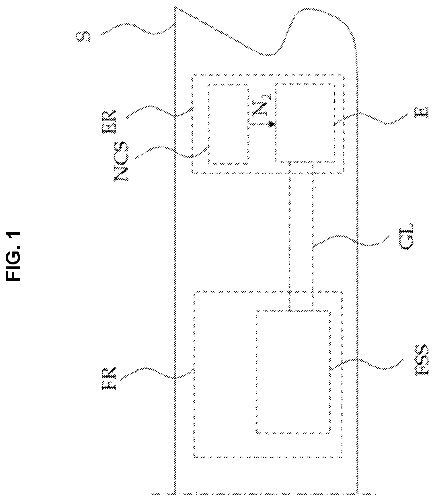
schematically illustrates a vessel including a nitrogen compression system for a leakage test on a gas pipeline used for an engine according to an embodiment of the present invention.
As illustrated in , the vessel including a nitrogen compression system NCS for a leakage test on a gas pipeline used for an engine according to an embodiment of the present invention includes a hull S, an engine room ER, and fuel supplying room FR including a fuel supplying system FSS for supplying fuel gas to an engine E.
The hull S may include various hulls such as a container hull and a liquefied gas hull.
The engine room ER may include the engine E for propelling the hull S and the nitrogen (N2) compression system NCS used for a leakage test. The engine E may be the ME-GA (low-pressure dual fuel propulsion) engine which uses fuel gas at low pressure of 10 through 15 bar. The nitrogen (N2) compression system NCS used for a leakage test may perform a leakage test on a gas pipeline GL in such a way that nitrogen N2 for a leakage test of the gas pipeline GL is compressed to generate compressed nitrogen and then, the generated compressed nitrogen is supplied to the gas pipeline GL of the fuel supplying system FSS.
The fuel supplying room FR may include the fuel supplying system FSS which supplies fuel gas to the engine E.
Hereinafter, the nitrogen compression system NCS for a leakage test on a gas pipeline used for an engine according to an embodiment of the present invention will be described in more detail.
schematically illustrates the nitrogen compression system NCS for a leakage test on a gas pipeline used for an engine according to an embodiment of the present invention.
As illustrated in , the nitrogen compression system NCS for a leakage test on a gas pipeline used for an engine according to an embodiment of the present invention includes a nitrogen generator 100 , a nitrogen storage tank 200 , an air compressor 300 , an air supplier 400 , an air storage tank 500 , a first diverter valve DV 1 , a second diverter valve DV 2 , an initial purging valve IPV, a first nitrogen decompression valve RV 1 , and a second nitrogen decompression valve RV 2 .
The nitrogen generator 100 is installed in the engine room ER included in the hull S and may generate nitrogen N2.
The nitrogen storage tank 200 adjacent to the nitrogen generator 100 is installed in the engine room ER and may store nitrogen generated from the nitrogen generator 100 . Nitrogen stored in the nitrogen storage tank 200 may have pressure of approximately 6 bar.
The air compressor 300 uses air supplied from the air supplier 400 to generate compressed air which helps in starting and controlling the engine E. The compressed air generated from the air compressor 300 is stored in the air storage tank 500 and then, may be supplied to the engine E through a compressed air pipeline CAL. The compressed air may have pressure of approximately 30 bar. Also, the compressed air may be supplied to a dual circulating pipeline DCL through an engine connecting pipeline ECL which connects the compressed air pipeline CAL to the dual circulating pipeline DCL of the engine E. An air decompression unit ARU and a flow switch FS may be installed on the engine connecting pipeline ECL. The air decompression unit ARU may supply circulating air to the dual circulating pipeline DCL of the engine E, wherein the circulating air is made by compressing and drying compressed air or compressed nitrogen of 30 bar into approximately 0.5 bar. The flow switch FS may identify whether the circulating air passing through the air decompression unit ARU is properly supplied to the dual circulating pipeline DCL of the engine E. When the circulating air is not flowed into the dual circulating pipeline DCL of the engine E, operation of the engine E is stopped.
The air supplier 400 may supply air to the air compressor 300 . The air supplier 400 may absorbs an atmosphere and may receive air.
The air storage tank 500 may store compressed air generated from the air compressor 300 . The compressed air stored in the air storage tank 500 is supplied to the engine E to assist starting and controlling of the engine E. An amount of the compressed air stored in the air storage tank 500 may be equivalent to an amount that enables the engine to start more than 12 times.
The first diverter valve DV 1 may be installed on a first diverter pipeline DL 1 which connects the air supplier 400 , nitrogen storage tank 200 , and the air compressor 300 . Such a first diverter valve DV 1 may be a 3-way valve. The first diverter pipeline DL 1 may include a (1-1)th diverter pipeline DL 11 , a (1-2)th diverter pipeline DL 12 , and a (1-3)th diverter pipeline DL 13 , wherein the (1-1)th diverter pipeline DL 11 connects the air supplier 400 to the first diverter valve DV 1 , the (1-2)th diverter pipeline DL 12 connects the nitrogen storage tank 200 to the first diverter valve DV 1 , and the (1-3)th diverter pipeline DL 13 connects the first diverter valve DV 1 to the air compressor 300 .
As the first diverter valve DV 1 is controlled, any one of air and nitrogen may be supplied to the air compressor 300 .
In an operation mode when the engine E is operated, the first diverter valve DV 1 is controlled to connect the diverter pipeline DL 11 to the (1-3)th diverter pipeline DL 13 . Accordingly, air may be supplied to the air compressor 300 from the air supplier 400 and thereby, compressed air may be generated. In addition, in a still mode when the engine E is stopped, the first diverter valve DV 1 is controlled to connect the (1-2)th diverter pipeline DL 12 to the (1-3)th diverter pipeline DL 13 . Accordingly, nitrogen may be supplied to the air compressor 300 from the nitrogen storage tank 200 and thereby, compressed nitrogen may be generated.
The second diverter valve DV 2 may be installed on a second diverter pipeline DL 2 which connects the air compressor 300 to the air storage tank 500 . Such a second diverter valve DV 2 may be a 3-way valve. The second diverter pipeline DL 2 may include a (2-1)th diverter pipeline DL 21 , a (2-2)th diverter pipeline DL 22 , and a (2-3)th diverter pipeline DL 23 , wherein the (2-1)th diverter pipeline DL 21 connects the air compressor 300 to the second diverter valve DV 2 , the 2-2)th diverter pipeline DL 22 connects the second diverter valve DV 2 to the air storage tank 500 , and the diverter pipeline DL 23 connects the second diverter valve DV 2 to the initial purging valve IPV.
As the second diverter valve DV 2 is controlled, compressed air generated from the air compressor 300 may be supplied to the air storage tank 500 or compressed nitrogen generated from the air compressor 300 may be supplied to the gas pipeline GL.
In an operation mode when the engine E is operated, the second diverter valve DV 2 is controlled to connect the (2-1)th diverter pipeline DL 21 to (2-2)th diverter pipeline DL 22 . Accordingly, compressed air generated from the air compressor 300 may be supplied to the air storage tank 500 and thereby, may be supplied to the dual circulating pipeline DCL of the engine E. In addition, in a still mode when the engine E is stopped, the second diverter valve DV 2 is controlled to connect the (2-1)th diverter pipeline DL 21 to the (2-3)th diverter pipeline DL 23 . Accordingly, compressed nitrogen generated from the air compressor 300 may be supplied to the gas pipeline GL. Here, a leakage test may be performed on the compressed nitrogen supplied to the gas pipeline GL by purging the gas pipeline GL. The gas pipeline GL may include a main gas pipeline MGL, a first gas pipeline GL 1 , and a second gas pipeline GL 2 .
The main gas pipeline MGL may connect the fuel supplying system FSS to the engine E and may supply fuel gas to the engine E from the fuel supplying system FSS. A gas valve train GVT, a main gas valve MGV, and a main venting valve MBV may be installed on the main gas pipeline MGL. The gas valve train GVT may control supply pressure of fuel gas supplied to the engine E. Also, while in a gas trip, the gas valve train GVT may vent fuel gas from the main gas pipeline MGL or purge the main gas pipeline MGL with compressed air. The main gas valve MGV may be installed at the front end of the gas valve train GVT and may block fuel gas supplied to the engine E in case of emergency. The main venting valve MBV may vent or purge fuel gas of the main gas pipeline MGL to the outside.
The first gas pipeline GL 1 may connect the initial purging valve IPV to the engine E. The first gas pipeline GL 1 may supply compressed nitrogen to the engine E, wherein the compressed nitrogen is used to perform a leakage test before the engine E starts. A first nitrogen purging block PB 1 may be installed on the first gas pipeline GL 1 . In a still mode when the engine E is stopped, the first nitrogen purging block PB 1 may be in a valve group which supplies compressed nitrogen to the first gas pipeline GL 1 and purges the first gas pipeline GL 1 . The first nitrogen purging block PB 1 may include a first dual control valve DCV 1 and a first venting valve VV 1 , wherein the first dual control valve DCV 1 prevents fuel gas to flow backward into the first gas pipeline GL 1 and the first venting valve VV 1 interposed between the first dual control valves DCV 1 vents leakage gas to the outside.
The second gas pipeline GL 2 may connect the first gas pipeline GL 1 to the main gas pipeline MGL. A second nitrogen purging block PB 2 may be installed on the second gas pipeline GL 2 . The second nitrogen purging block PB 2 may be in a valve group which supplies compressed nitrogen to the second gas pipeline GL 2 disposed at the front end of the gas valve train GVT to vent, purge, and perform a leakage test on the second gas pipeline GL 2 . The second nitrogen purging block PB 2 may include a second dual control valve DCV 2 and a second venting valve VV 2 , wherein the second dual control valve DCV 2 prevents fuel gas to flow backward into the second gas pipeline GL 2 and the second venting valve VV 2 interposed between the second dual control valves DCV 2 vents leakage gas to the outside.
The initial purging valve IPV may be interposed between the second diverter valve DV 2 and the first gas pipeline GL 1 . That is, the initial purging valve IPV may be a 3-way valve which is connected to the (2-3)th diverter pipeline DL 23 , an initial purging pipeline IPL, and the first gas pipeline GL 1 .
When the first diverter valve DV 1 is controlled to supply nitrogen to the air compressor 300 , the second diverter valve DV 2 and the initial purging valve IPV may be controlled to discharge compressed air to the outside through the initial purging pipeline IPL for a predetermined time. The initial purging pipeline IPL may be connected to the dual circulating pipeline DCL of the engine E through the engine connecting pipeline ECL. Accordingly, compressed air remaining in the (2-1)th diverter pipeline DL 21 and the (2-3)th diverter pipeline DL 23 at the beginning may be supplied to the dual circulating pipeline DCL of the engine E through the initial purging pipeline IPL and thereby, a function of the air compressor 300 may be improved. Also, compressed nitrogen may be supplied to the dual circulating pipeline DCL of the engine E through the initial purging pipeline IPL and thereby, a function of the air compressor 300 may be improved.
When the first diverter valve DV 1 is controlled to supply air to the air compressor 300 , the second diverter valve DV 2 and the initial purging valve IPV may be controlled to discharge compressed nitrogen to the outside through the initial purging pipeline IPL for a predetermined time.
The first nitrogen decompression valve RV 1 may be installed on the (1-2)th diverter pipeline DL 12 of the first diverter pipeline DL 1 . When pressure of gas acceptable to the air compressor 300 is fixed and the air compressor 300 is not able to receive nitrogen at pressure of 6 bar from the nitrogen storage tank 200 , the first nitrogen decompression valve RV 1 may reduce pressure of nitrogen supplied from the nitrogen storage tank 200 to the air compressor 300 from 6 bar to atmospheric pressure to be supplied to the air compressor 300 .
The second nitrogen decompression valve RV 2 may be installed on the gas pipeline GL disposed at the back end of the initial purging valve IPV. The second nitrogen decompression valve RV 2 may reduce pressure of compressed nitrogen from 30 bar to 15 bar to be supplied to gas pipelines.
A nitrogen purging valve NPV may be installed on a nitrogen supply pipeline NSL which connects the nitrogen storage tank 200 to the gas pipeline GL. In a still mode when the engine E is stopped or a manual mode, the nitrogen purging valve NPV may supply nitrogen at pressure of 6 bar stored in the nitrogen storage tank 200 to the gas pipeline GL and may purge the gas pipeline GL.
In the nitrogen compression system for a leakage test on a gas pipeline used for an engine according to an embodiment of the present invention described above, the air compressor 300 which supplies compressed air to support starting of the engine E, the first diverter valve DV 1 , and the second diverter valve DV 2 are used to compress nitrogen and thereby, compressed nitrogen is generated. Then, the generated compressed nitrogen is used to perform a leakage test on the gas pipeline GL. Accordingly, a high-priced compressor for generating compressed nitrogen is not separately needed and thereby, a leakage test may be performed at a low cost.
Also, the air compressor 300 which supplies compressed air used to support starting of the engine E to the engine E has a capacity greater by 10 times than that of a separate compressor and thereby, the time required for the leakage test on the gas pipeline GL may be reduced.
In addition, the nitrogen generator 100 , the nitrogen storage tank 200 , the air compressor 300 , the air supplier 400 , and the air storage tank 500 are disposed in the engine room ER and thereby, the nitrogen compression system for a leakage test connected to the engine E may be easily formed and arranged.
While the present invention has been particularly shown and described with reference to exemplary embodiments thereof, it will be understood by those of ordinary skill in the art that various changes in form and details may be made therein without departing from the spirit and scope of the present invention as defined by the following claims.
Figures (2)
Citations
This patent cites (24)
- US2019/0383290
- US2024/0280221
- US106153275
- US102007035163
- US2915986
- US2915986
- US2004317170
- US3628390
- US2011167602
- US10-2004-0100467
- US100916662
- US101069897
- US20-2014-0004120
- US20140004120
- US20-2014-0005774
- US10-1884766
- US10-2020-0022873
- US20200022873
- US10-2021-0017156
- US20210017156
- US102333073
- US20230055692
- US102552635
- US20240008626