Abstract
A closure assembly including: a cap with an inner surface and an outer surface opposite to the inner surface, the inner surface including an interface configured to cooperate with a finish of a fluid reservoir to close the fluid reservoir, and the outer surface including an icon; and a plate mounted to the cap over the outer surface with a retention member, the plate defining an opening through which the icon is visible. The plate is removable from the cap by detaching or severing the retention member.
Claims (17)
1 . A closure assembly comprising: a cap including an inner surface and an outer surface opposite to the inner surface, the inner surface including an interface configured to cooperate with a finish of a fluid reservoir to close the fluid reservoir, and the outer surface including an icon at a cap center of the cap; a plate mounted to the cap over the outer surface with a retention member that is offset from a plate center of the plate, the plate defining an opening at the plate center through which the icon is visible; and an anti-rotation member configured to prevent rotation of the plate relative to the cap, the anti-rotation member is independent of the retention member, wherein the plate is removable from the cap by detaching or severing the retention member.
11 . A closure assembly comprising: a cap including an inner surface and an outer surface opposite to the inner surface, the inner surface including an interface configured to cooperate with a finish of a brake fluid reservoir of an automobile to close the brake fluid reservoir, and the outer surface including a brake fluid icon at a cap center of the cap; a plate mounted to the cap over the outer surface with a retention member that is offset from a plate center of the plate and in contact with both the plate and the cap, the plate is rotatable about the retention member, the plate including warning text at an outer plate surface of the plate, and the plate defining an opening at the plate center through which the brake fluid icon is visible; and an anti-rotation member configured to prevent rotation of the plate relative to the cap, the anti-rotation member is independent of the retention member, wherein the plate is removable from the cap by detaching or severing the retention member.
16 . A closure assembly comprising: a cap including an inner surface and an outer surface opposite to the inner surface, the inner surface including an interface configured to cooperate with a finish of a brake fluid reservoir of an automobile to close the brake fluid reservoir, and the outer surface including a brake fluid icon at a cap center of the cap; a plate mounted to the cap over the outer surface with a retention member that is offset from a plate center of the plate and in contact with both the plate and the cap, the plate is rotatable about the retention member, the plate including warning text at an outer plate surface of the plate, and the plate defining an opening at the plate center through which the brake fluid icon is visible; a break-away area of the plate proximate to the retention member to facilitate decoupling of the plate from the retention member, the break-away area of the plate is relatively thinner than an adjacent area of the plate; and an anti-rotation surface protruding from the outer surface of the cap, the anti-rotation surface configured to cooperate with the plate to restrict rotation of the plate relative to the cap, the anti-rotation surface is independent of the retention member, wherein the plate is removable from the cap by detaching or severing the retention member.
Show 14 dependent claims
2 . The closure assembly of claim 1 , wherein the icon at the outer surface of the cap is a brake fluid icon.
3 . The closure assembly of claim 1 , wherein the outer surface of the cap further includes a check owner's manual icon and DOT 4 text.
4 . The closure assembly of claim 1 , wherein the plate includes warning text at an outer plate surface of the plate.
5 . The closure assembly of claim 1 , wherein the plate further includes a break-away area proximate to the retention member to facilitate decoupling of the plate from the retention member, the break-away area of the plate is relatively thinner than an adjacent area of the plate.
6 . The closure assembly of claim 1 , wherein the anti-rotation member includes a knob protruding from the outer surface of the cap, the knob configured to cooperate with an inner plate surface of the plate to restrict rotation of the plate relative to the cap.
7 . The closure assembly of claim 1 , wherein the anti-rotation member includes a rod extending from the outer surface of the cap and the plate defines a receptacle at an outer perimeter thereof configured to couple to the rod to restrict rotation of the plate relative to the cap.
8 . The closure assembly of claim 1 , wherein the retention member is a fastener including a head and a body extending through a plate aperture of the plate and seated in a cap aperture of the cap.
9 . The closure assembly of claim 1 , wherein the retention member is a post extending from the outer surface of the cap, the post is integrally molded with the cap.
10 . The closure assembly of claim 9 , wherein the post includes a head and a rod, the plate is rotatable about the rod.
12 . The closure assembly of claim 11 , wherein the retention member is integrally molded with the cap.
13 . The closure assembly of claim 11 , wherein the retention member is a fastener including a head and a body extending through a plate aperture defined by the plate and into a cap aperture defined by the cap.
14 . The closure assembly of claim 11 , wherein the anti-rotation member includes a knob protruding from the outer surface of the cap, the knob configured to cooperate with an inner plate surface of the plate to restrict rotation of the plate relative to the cap.
15 . The closure assembly of claim 11 , wherein the anti-rotation member includes a rod extending from the outer surface of the cap and the plate defines a receptacle at an outer perimeter thereof configured to couple to the rod to restrict rotation of the plate relative to the cap.
17 . The closure assembly of claim 16 , wherein the retention member is integrally molded with the cap.
Full Description
Show full text →
INTRODUCTION
The information provided in this section is for the purpose of generally presenting the context of the disclosure. Work of the presently named inventors, to the extent it is described in this section, as well as aspects of the description that may not otherwise qualify as prior art at the time of filing, are neither expressly nor impliedly admitted as prior art against the present disclosure.
The present disclosure relates to a brake fluid reservoir cap configured to cooperate with a finish of a brake fluid reservoir for an automobile.
Vehicles include a brake fluid reservoir in which brake fluid is stored. The reservoir is closed with a cap. Regulatory authorities mandate that various information be included on the cap. The information that must be included varies across different jurisdictions. Thus, different brake caps with different information must be used depending on where the vehicle is to be sold.
SUMMARY
The present disclosure provides for, in various features, a closure assembly including: a cap including an inner surface and an outer surface opposite to the inner surface, the inner surface including an interface configured to cooperate with a finish of a fluid reservoir to close the fluid reservoir, and the outer surface including an icon; and a plate mounted to the cap over the outer surface with a retention member, the plate defining an opening through which the icon is visible. The plate is removable from the cap by detaching or severing the retention member.
In further features, the icon at the outer surface of the cap is a brake fluid icon.
In further features, the closure assembly of claim 1 , wherein the outer surface of the cap further includes a check owner's manual icon and DOT 4 text.
In further features, the plate includes warning text at an outer plate surface of the plate.
In further features, the retention member is a first retention member, the closure assembly further including a second retention member that is opposite to the first retention member, the second retention member mounting the plate to the cap.
In further features, the plate further includes a break-away area proximate to the retention member to facilitate decoupling of the plate from the retention member, the break-away area of the plate is relatively thinner than an adjacent area of the plate.
In further features, the cap further includes a knob protruding from the outer surface of the cap, the knob configured to cooperate with an inner plate surface of the plate to restrict rotation of the plate relative to the cap.
In further features, the cap further includes a rod extending from the outer surface of the cap and the plate defines a receptacle at an outer perimeter thereof configured to couple to the rod to restrict rotation of the plate relative to the cap.
In further features, the retention member is a fastener extending through a plate aperture of the plate and seated in a cap aperture of the cap.
In further features, the retention member is a post extending from the outer surface of the cap, the post is integrally molded with the cap.
In further features, the post includes a head and a rod, the plate is rotatable about the rod.
The present disclosure also includes, in various features, a closure assembly including: a cap including an inner surface and an outer surface opposite to the inner surface, the inner surface including an interface configured to cooperate with a finish of a brake fluid reservoir of an automobile to close the brake fluid reservoir, and the outer surface including a brake fluid icon; and a plate mounted to the cap over the outer surface with a retention member in contact with both the plate and the cap, the plate is rotatable about the retention member, the plate including warning text at an outer plate surface of the plate, and the plate defining an opening through which the brake fluid icon is visible. The plate is removable from the cap by detaching or severing the retention member.
In further features, the retention member is integrally molded with the cap.
In further features, the retention member is a first retention member, the closure assembly further including a second retention member that is opposite to the first retention member, the second retention member mounting the plate to the cap.
In further features, the retention member is a first fastener extending through a plate aperture defined by the plate and into a cap aperture defined by the cap.
In further features, a second fastener extends through the plate and into cooperation with the cap.
In further features, a knob protrudes from the outer surface of the cap, the knob configured to cooperate with an inner plate surface of the plate to restrict rotation of the plate relative to the cap.
In further features, the cap further includes a rod extending from the outer surface of the cap and the plate defines a receptacle at an outer perimeter thereof configured to couple to the rod to restrict rotation of the plate relative to the cap.
The present disclosure further includes, in various features, a closure assembly including: a cap including an inner surface and an outer surface opposite to the inner surface, the inner surface including an interface configured to cooperate with a finish of a brake fluid reservoir of an automobile to close the brake fluid reservoir, and the outer surface including a brake fluid icon; a plate mounted to the cap over the outer surface with a retention member in contact with both the plate and the cap, the plate is rotatable about the retention member, the plate including warning text at an outer plate surface of the plate, and the plate defining an opening through which the brake fluid icon is visible; a break-away area of the plate proximate to the retention member to facilitate decoupling of the plate from the retention member, the break-away area of the plate is relatively thinner than an adjacent area of the plate; and an anti-rotation surface protruding from the outer surface of the cap, the anti-rotation surface configured to cooperate with the plate to restrict rotation of the plate relative to the cap. The plate is removable from the cap by detaching or severing the retention member.
In further features, the retention member is integrally molded with the cap.
Further areas of applicability of the present disclosure will become apparent from the detailed description, the claims, and the drawings. The detailed description and specific examples are intended for purposes of illustration only and are not intended to limit the scope of the disclosure.
BRIEF DESCRIPTION OF THE DRAWINGS
The present disclosure will become more fully understood from the detailed description and the accompanying drawings, wherein:
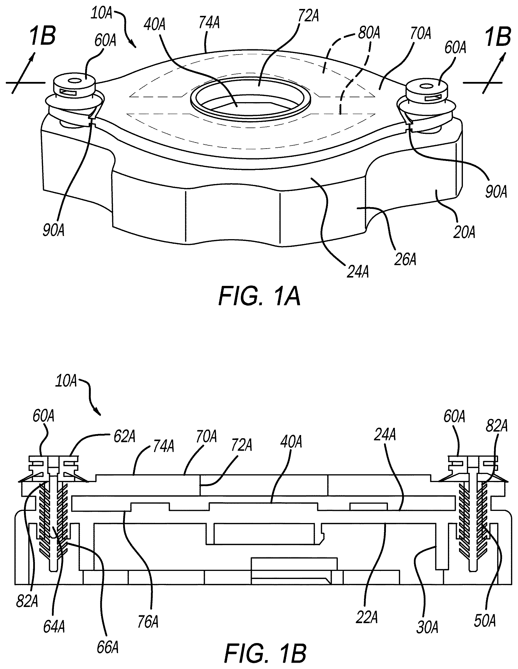
A is a perspective view of a first closure assembly in accordance with the present disclosure, the first closure assembly including a cap and a plate mounted to the cap;
B is a cross-sectional view of A , taken along line 1 B- 1 B of A ;
C is a perspective view of the cap of A with the plate removed therefrom;
A is a perspective view of a second closure assembly in accordance with the present disclosure, the second closure assembly including a cap and a plate mounted to the cap;
B is a cross-sectional view taken along line 2 B- 2 B of A ;
C is a plan view of the second closure assembly with the plate rotated relative to the cap;
A is a perspective view of a third closure assembly in accordance with the present disclosure, the third closure assembly including a cap and a plate mounted to the cap;
B is a cross-sectional view taken along line 3 B- 3 B of A ;
C is a plan view of the third closure assembly with the plate rotated relative to the cap;
A is a perspective view of a fourth closure assembly in accordance with the present disclosure, the fourth closure assembly including a cap and a plate mounted to the cap; and
B is a perspective view of the cap of the fourth closure assembly with the plate removed from cooperation with the cap.
In the drawings, reference numbers may be reused to identify similar and/or identical elements.
DETAILED DESCRIPTION
The present disclosure is directed to a closure assembly, such as for a fluid reservoir. The closure assembly may be configured to cooperate with a finish of any suitable fluid reservoir, such as a brake fluid reservoir of an automobile. The closure assembly may be configured for non-automotive uses as well.
Regulatory authorities mandate that various information be printed on a cap for a brake fluid reservoir. The information required varies across different jurisdictions. For example, the information required to be printed on a brake fluid cap for a vehicle to be sold in the United States may be different from the information required to be printed on a brake fluid cap for a vehicle to be sold in the United Kingdom or elsewhere outside of the United States. Traditionally, selecting the correct cap to be used on a vehicle complicated assembly. The present disclosure provides for a closure assembly including the information of multiple different jurisdictions, thereby allowing the closure assembly of the present disclosure to be installed on a vehicle regardless of the jurisdiction where the vehicle is intended to be sold. The closure assembly of the present disclosure thus simplifies assembly and reduces assembly time.
A, 1 B, and 1 C illustrate a first closure assembly 10 A in accordance with the present disclosure. The closure assembly 10 A is configured to close a fluid reservoir of any suitable fluid, such as brake fluid. The closure assembly 10 A is configured for use in both automotive and non-automotive applications.
The first closure assembly 10 A generally includes a cap 20 A and a plate 70 A removably mounted to the cap 20 A with any suitable retention members, such as the retention members 60 A. As described herein, both the cap 20 A and the plate 70 A include various information printed thereon in the form of text and/or icons. The plate 70 A may include text relevant to a first jurisdiction, such as the United States for example, and the cap 20 A may include text relevant to a second jurisdiction, such as the United Kingdom, for example. In situations where the first closure assembly 10 A is installed on a vehicle intended to be sold in the second jurisdiction, the plate 70 A will be removed from the cap 20 A to expose information on the cap 20 A.
The cap 20 A generally includes an inner surface 22 A ( B ), an outer surface 24 A opposite to the inner surface 22 A, and a side surface 26 A. The inner surface 22 A includes an interface 30 A, which is configured to cooperate with a finish of a brake fluid reservoir of an automobile to close the brake fluid reservoir. The side surface 26 A may include various concave and convex surfaces to facilitate grasping of the cap 20 A.
The outer surface 24 A of the cap 20 A includes information and/or warnings relevant to a particular jurisdiction. For example and with particular reference to C , the outer surface 24 A includes a brake fluid icon 40 A, such as at a center of the outer surface 24 A. The illustrated icon is an internationally accepted icon. Any other suitable icon may alternatively be included. The outer surface 24 A further includes a text box 42 A, which may include any text relevant to a particular jurisdiction, such as “DOT4,” for example. Any other suitable icons may be included, such as a check owner's manual icon 44 A, which is generally understood to be an instruction to a user to check the owner's manual for additional information. The icons and text shown in the figures at the outer surface 24 A are merely exemplary. The outer surface 24 A may be configured with any other suitable icons and text relevant to a particular jurisdiction. The cap 20 A further includes cap apertures 50 A, which are defined by the cap 20 A and extend from the outer surface 24 A into the cap 20 and are configured to receive the retention members 60 A for fastening the plate 70 A to the cap 20 A, as further described herein.
The plate 70 A defines an opening 72 A, and includes an outer surface 74 A and an inner surface 76 A, which is opposite to the outer surface 74 A. When the plate 70 A is mounted to the cap 20 A, the opening 72 A is aligned with the brake fluid icon 40 A such that the brake fluid icon is visible through the opening 72 A. At the outer surface 74 A is printed information and/or warnings that are relevant to a particular jurisdiction where the vehicle may be sold. For example, the outer surface 74 A may include two areas 80 A of text. One of the areas 80 A may have the text printed in a first language, such as English, and another area 80 A may have the text printed in a second language, such a French. Exemplary language may include the following in English: “WARNING: CLEAN FILLER CAP BEFORE REMOVING. USE ONLY DOT4 FLUID FROM A SEALED CONTAINER.” This language may be printed in French also, for example.
The plate 70 A defines plate apertures 82 A, which are aligned with the cap apertures 50 A. The plate 70 A is mounted to the cap 20 A such that the inner surface 76 A faces the outer surface 24 A of the cap 20 A. In the example of A- 1 C , the plate 70 A is mounted to the cap 20 A with the retention members 60 A. The plate 70 A may be mounted to the cap 20 A in any other suitable manner, such as described herein with respect to the closure assemblies 10 B, 10 C, and 10 D. The retention members 60 A each include a head 62 A and a body 64 A. Extending from the body 64 A are retention tabs 66 A. The retention tabs 66 A extend from the body 64 A at an angle towards the head 62 A to facilitate retention of the body 64 A within the cap aperture 50 A. In the example illustrated, two of the retention members 60 A are included, which prevents the plate 70 A from rotating relative to the cap 20 A. Adjacent to the plate apertures 82 A, the plate 70 A defines break-away areas 90 A, which are areas of the plate 70 that are relatively thinner than surrounding areas of the plate 70 A. As explained below, the break-away areas 90 A facilitate detachment of the plate 70 A. In addition to the break-away areas shown in A , additional break-away areas may be included on sides of the retention members 60 A opposite to the break-away areas 90 A, and the additional break-away areas may extend generally perpendicular to the break-away areas 90 A and extend to the plate apertures 82 A.
In jurisdictions where the text included at areas 80 A is required, the closure assembly 10 A is installed on a vehicle with the plate 70 A mounted to the cap 20 A. With the plate 70 A mounted to the cap 20 A, the brake fluid icon 40 A is visible through the opening 72 A of the plate 70 A, but the text box 42 A and the icon 44 A are covered by the plate 70 A. In jurisdictions where the text at text box 42 A and the icon 44 A are required instead of the text at area 80 A, the plate 70 A is detached from the cap 20 A prior to installation of the closure assembly 10 A. The plate 70 A may be detached from the cap 20 A in any suitable manner. For example, the retention members 60 A may be removed. One or both of the retention members 60 A may be severed in any suitable manner, such as with any suitable cutting device. If only one of the retention members 60 A is severed, the plate 70 A may be separated at the break-away area 90 A opposite to the severed retention member 60 A to completely remove the plate 70 A. The plate 70 A may also be severed at the break-away areas 90 A without severing the retention members 60 A.
A, 2 B, and 2 C illustrate an additional closure assembly 10 B in accordance with the present disclosure. The closure assembly 10 B is similar to the closure assembly 10 A, and thus features of the closure assembly 10 B that are the same as, or similar to, features of the closure assembly 10 A are identified in the drawings with the same reference numbers but with the suffix “B” instead of “A.” With respect to the like or similar features, unless otherwise stated, the description of the closure assembly 10 A also applies to the closure assembly 10 B.
Unlike the closure assembly 10 A, the closure assembly 10 B includes only a single retention member 60 B. The retention member 60 B may be the same as the retention member 60 A, or be any other suitable retention member/fastener. In the example illustrated, the retention member 60 B includes a head 62 B and a body 64 B. The body 64 B includes a tab suitable for retaining the body 64 B within the cap aperture 50 B. The body 64 B may in some applications include the retention tabs 66 A. The retention member 60 B extends through the plate aperture 82 B, and the plate 70 B is able to rotate about the body 64 B. Rotation of the plate 70 B is restricted by a retention knob 92 B. The retention knob 92 B protrudes from the outer surface 24 B of the cap 20 B. The retention knob 92 B is sized and shaped to cooperate with a receptacle 94 B at the inner surface 76 B of the plate 70 B to restrict rotation of the plate 70 B.
In jurisdictions where the text included at areas 80 B is required, the closure assembly 10 B is installed on a vehicle with the plate 70 B mounted to the cap 20 A covering the outer surface 24 B. With the plate 70 B mounted to the cap 20 B, the brake fluid icon 40 B is visible through the opening 72 B of the plate 70 B, but the text box 42 B and the icon 44 B are covered by the plate 70 B. In jurisdictions where the text at text box 42 B and the icon 44 B are required instead of the text at area 80 B, the plate 70 B is detached from the cap 20 B prior to installation of the closure assembly 10 B. The plate 70 B may be detached from the cap 20 B in any suitable manner. For example, the plate 70 B may be rotated about the retention member 60 B as illustrated in C , and the plate 70 B may be broken off at the break-away area 90 B by applying force to the plate 70 B. An additional break-away area 90 B′ extending to the plate aperture 82 B will facilitate removing the plate 70 B in its entirety. The retention member 60 B may also be cut using any suitable cutting device, or the retention member 60 B may be removed in any other suitable manner.
A, 3 B, and 3 C illustrate an additional closure assembly 10 C in accordance with the present disclosure. The closure assembly 10 C is similar to the closure assembly 10 A and the closure assembly 10 B, and thus features of the closure assembly 10 C that are the same as, or similar to, features of the closure assembly 10 A and the closure assembly 10 B are identified in the drawings with the same reference numbers but with the suffix “C” instead of “A” or “B.” With respect to the like or similar features, unless otherwise stated, the descriptions of the closure assembly 10 A and the closure assembly 10 B also apply to the closure assembly 10 C.
The cap 20 C includes a rod 92 C instead of the retention knob 92 B. The rod 92 C is sized, shaped, and positioned to cooperate with a receptacle 94 C defined at an outer perimeter of the plate 70 C. Cooperation between the rod 92 C and the receptacle 94 C restricts rotation of the plate 70 C relative to the cap 20 C.
In jurisdictions where the text included at areas 80 C is required, the closure assembly 10 C is installed on a vehicle with the plate 70 C mounted to the cap 20 C covering the outer surface 24 C. With the plate 70 C mounted to the cap 20 C, the brake fluid icon 40 C is visible through the opening 72 C of the plate 70 C, but the text box 42 C and the icon 44 C are covered by the plate 70 C. In jurisdictions where the text at text box 42 C and the icon 44 C are required instead of the text at area 80 C, the plate 70 C is detached from the cap 20 C prior to installation of the closure assembly 10 C. The plate 70 C may be detached from the cap 20 C in any suitable manner. For example, the plate 70 C may be rotated about the retention member 60 C as illustrated in C , which will include detaching the rod 92 C from the receptacle 94 C, and the plate 70 C may be broken off at the break-away area 90 C by applying force to the plate 70 C. An additional break-away area 90 C′ extending to the plate aperture through which the retention member 60 C extends will facilitate removing the plate 70 C in its entirety. The retention member 60 C may also be cut using any suitable cutting device, or the retention member 60 C may be removed in any other suitable manner.
A and 4 B illustrate another closure assembly 10 D in accordance with the present disclosure. The closure assembly 10 D is similar to the closure assembly 10 A, the closure assembly 10 B, and the closure assembly 10 C, and thus features of the closure assembly 10 C that are the same as, or similar to, features of the closure assemblies 10 A, 10 B, and 10 C are identified in the drawings with the same reference numbers but with the suffix “D” instead of “A,” “B,” or “C.” With respect to the like or similar features, unless otherwise stated, the descriptions of the closure assemblies 10 A, 10 B, and 10 C also apply to the closure assembly 10 D.
With particular reference to B , the retention members 60 D are integrally molded with the cap 20 D. More specifically, the retention members 60 D are initially molded to include the bodies 64 D (which in this example are posts), but not the heads 62 D. To attach the plate 70 D to the retention members 60 D, the plate 70 D is seated over the bodies 64 D (or posts) such that the bodies 64 D (or posts) extend through the plate apertures 82 C defined by the plate 70 D. Then, using any suitable process, the bodies 64 D (or posts) are flattened to form the heads 62 D over the plate 70 D. The heads 62 D secure the plate 70 D to the cap 20 D. The heads 62 D may be formed in any suitable manner. For example, the heads 62 D may be formed by any suitable welding process, such as sonic welding. To remove the plate 70 D, the retention members 60 D may be severed in any suitable manner, such as with any suitable cutting tool. The plate 70 D may also be detached at break-away areas 90 D.
In jurisdictions where the text included at areas 80 D is required, the closure assembly 10 D is installed on a vehicle with the plate 70 D mounted to the cap 20 D covering the outer surface 24 D. With the plate 70 D mounted to the cap 20 D, the brake fluid icon 40 D is visible through the opening 72 D of the plate 70 D, but the text box 42 D and the icon 44 D are covered by the plate 70 D. In jurisdictions where the text at text box 42 D and the icon 44 D are required instead of the text at area 80 D, the plate 70 D is detached from the cap 20 D prior to installation of the closure assembly 10 C. The plate 70 D may be detached from the cap 20 D in any suitable manner, such as by severing the retention members 60 D with any suitable cutting device.
The foregoing description is merely illustrative in nature and is in no way intended to limit the disclosure, its application, or uses. The broad teachings of the disclosure can be implemented in a variety of forms. Therefore, while this disclosure includes particular examples, the true scope of the disclosure should not be so limited since other modifications will become apparent upon a study of the drawings, the specification, and the following claims. It should be understood that one or more steps within a method may be executed in different order (or concurrently) without altering the principles of the present disclosure. Further, although each of the embodiments is described above as having certain features, any one or more of those features described with respect to any embodiment of the disclosure can be implemented in and/or combined with features of any of the other embodiments, even if that combination is not explicitly described. In other words, the described embodiments are not mutually exclusive, and permutations of one or more embodiments with one another remain within the scope of this disclosure.
Spatial and functional relationships between elements (for example, between modules, circuit elements, semiconductor layers, etc.) are described using various terms, including “connected,” “engaged,” “coupled,” “adjacent,” “next to,” “on top of,” “above,” “below,” and “disposed.” Unless explicitly described as being “direct,” when a relationship between first and second elements is described in the above disclosure, that relationship can be a direct relationship where no other intervening elements are present between the first and second elements, but can also be an indirect relationship where one or more intervening elements are present (either spatially or functionally) between the first and second elements. As used herein, the phrase at least one of A, B, and C should be construed to mean a logical (A OR B OR C), using a non-exclusive logical OR, and should not be construed to mean “at least one of A, at least one of B, and at least one of C.”
In the figures, the direction of an arrow, as indicated by the arrowhead, generally demonstrates the flow of information (such as data or instructions) that is of interest to the illustration. For example, when element A and element B exchange a variety of information but information transmitted from element A to element B is relevant to the illustration, the arrow may point from element A to element B. This unidirectional arrow does not imply that no other information is transmitted from element B to element A. Further, for information sent from element A to element B, element B may send requests for, or receipt acknowledgements of, the information to element A.
Figures (6)
Citations
This patent cites (7)
- US594274
- US2145212
- US5984122
- US11873146
- US2020/0317411
- US2023/0356897
- US101455171