Abstract
A drug supply apparatus of the present disclosure includes a drug supply unit configured to supply a drug to a drug delivery position; a downstream conveying unit configured to convey a strip-shaped first drug packaging paper, folded in half in advance along its longitudinal direction, in such a way that the first drug packaging paper receives the drug at the drug delivery position; an upstream conveying unit configured to convey a strip-shaped second drug packaging paper folded in half in advance along its longitudinal direction toward the first drug packaging paper; and a connecting part configured to connect a downstream end part of the second drug packaging paper to the first drug packaging paper.
Claims (10)
1 . A drug supply apparatus, comprising: a drug supply unit configured to supply a drug to a drug delivery position; a downstream conveying unit configured to convey a first drug packaging paper in such a way that the first drug packaging paper receives the drug at the drug delivery position, wherein the first drug packaging paper is strip shaped and folded in half in advance along a longitudinal direction of the first drug packaging paper; an upstream conveying unit configured to convey a second drug packaging paper toward the first drug packaging paper, wherein the second drug packaging paper is strip shaped and folded in half in advance along a longitudinal direction of the second drug packaging paper; and a connecting part configured to connect a downstream end part of the second drug packaging paper to the first drug packaging paper, wherein: the downstream conveying unit includes a pair of downstream rollers, the upstream conveying unit includes a first upstream guide member, a second upstream guide member, a first pair of rollers, a second pair of rollers, and a moving member, the first upstream guide member, the second upstream guide member, the first pair of rollers, and the second pair of rollers are disposed in the moving member, and the first upstream guide member has a plate shape, and the first upstream guide member is configured to guide the first drug packaging paper with the first upstream guide member being sandwiched by the first drug packaging paper.
Show 9 dependent claims
2 . The drug supply apparatus according to claim 1 , further comprising: a packaging paper holding part configured to hold a package of the second drug packaging paper.
3 . The drug supply apparatus according to claim 2 , wherein the packaging paper holding part is configured to further hold a package of the first drug packaging paper.
4 . The drug supply apparatus according to claim 1 , wherein the connecting part includes a pressing part configured to press a connecting member that is configured to connect the first drug packaging paper with the second drug packaging paper.
5 . The drug supply apparatus according to claim 1 , further comprising: a cutting part configured to cut the first drug packaging paper, wherein the connecting part connects the downstream end part of the second drug packaging paper to an upstream end part of the first drug packaging paper, the upstream end part being formed when the cutting part cuts the first drug packaging paper.
6 . The drug supply apparatus according to claim 5 , wherein the upstream conveying unit conveys the second drug packaging paper in such a way that the downstream end part of the second drug packaging paper holds, in an inside of the downstream end part, the upstream end part of the first drug packaging paper, and a ridge line of the second drug packaging paper overlaps a ridge line of the first drug packaging paper.
7 . The drug supply apparatus according to claim 5 , wherein the moving member is configured to move the second drug packaging paper in such a way that the downstream end part of the second drug packaging paper faces the upstream end part of the first drug packaging paper.
8 . The drug supply apparatus according to claim 1 , wherein the second upstream guide member has a plate shape, and the second upstream guide member is configured to guide the second drug packaging paper with the second upstream guide member being sandwiched by the second drug packaging paper.
9 . The drug supply apparatus according to claim 1 , further comprising: a pair of holding members disposed between the upstream conveying unit and the downstream conveying unit, and each of the pair of holding members has a plate shape.
10 . The drug supply apparatus according to claim 1 , wherein the moving member is configured to be located at a first guide position and a second guide position, when the moving member is located at the first guide position, the first pair of rollers guide the first drug packaging paper without nipping the first drug packaging paper, and the first upstream guide member guides the first drug packaging paper, when the moving member is located at the second guide position, the second pair of rollers nip and convey the second drug packaging paper, and the second upstream guide member guides the second drug packaging paper at the time of replacing the first drug packaging paper with the second drug packaging paper, and a position of the second upstream guide member when the moving member is located at the second guide position is the same as a position of the first upstream guide member when the moving member is located at the first guide position.
Full Description
Show full text →
CROSS-REFERENCE OF RELATED APPLICATIONS
This is a Continuation of International Application No. PCT/JP2022/035218, filed on Sep. 21, 2022, which claims priority to Japanese Patent Application No. 2021-159486, filed on Sep. 29, 2021, the entire disclosures each of which are hereby incorporated by reference.
TECHNICAL FIELD
The present disclosure relates to a drug supply apparatus.
BACKGROUND ART
Patent Literature (hereinafter, referred to as PTL) 1 discloses a packaging paper connecting apparatus used for replacing old packaging paper with new packaging paper—the packaging paper has been folded in half in advance along the longitudinal direction thereof and is used to package a drug. The packaging paper connecting apparatus connects the terminal end of the old wrapping paper to the starting end of the new packaging paper. An operator manually overlaps the terminal end of the old packaging paper and the starting end of the new packaging paper, and places the overlapped portions at a predetermined position. As the operator connects the overlapped portions to each other, the terminal end of the old packaging paper and the starting end of the new packaging paper are connected.
CITATION LIST
Patent Literature
PTL 1
•
• Japanese Patent No. 5577526
SUMMARY OF INVENTION
Technical Problem
In the packaging paper connecting apparatus of PTL 1, an operator manually replaces packaging paper. In addition, during the replacing of the packaging paper, the packaging of a drug is stopped and the drug is not supplied. Therefore, when the time required to replace the packaging paper increases because, for example, the operator is not accustomed to replace the packaging paper, the time during which a drug is not supplied increases and, as a result, the patient's waiting time increases.
An object of the present disclosure is to shorten the time required to replace packaging paper in a drug supply apparatus.
Solution to Problem
A drug supply apparatus of the present disclosure includes the following: a drug supply unit configured to supply a drug to a drug delivery position; a downstream conveying unit configured to convey a first drug packaging paper in such a way that the first drug packaging paper receives the drug at the drug delivery position, in which the first drug packaging paper is strip shaped and folded in half in advance along a longitudinal direction of the first drug packaging paper; an upstream conveying unit configured to convey a second drug packaging paper toward the first drug packaging paper, in which the second drug packaging paper is strip shaped and folded in half in advance along a longitudinal direction of the second drug packaging paper; and a connecting part configured to connect a downstream end part of the second drug packaging paper to the first drug packaging paper.
Advantageous Effects of Invention
A drug supply apparatus of the present disclosure is capable of shortening the time required to replace packaging paper.
BRIEF DESCRIPTION OF DRAWING
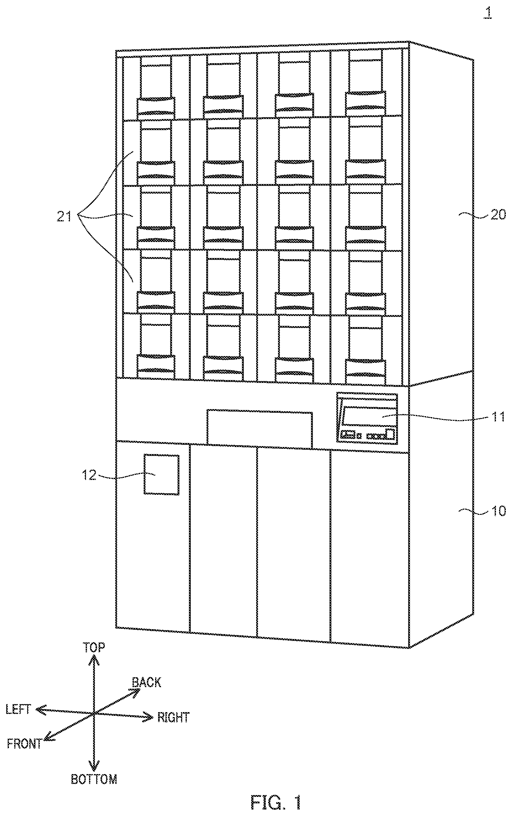
is a perspective view of a drug supply apparatus according to an embodiment of the present disclosure;
is a longitudinal cross-sectional view of the drug supply apparatus;
schematically illustrates a portion of a conveying part;
is a partially enlarged view of ;
illustrates the side and a periphery of first drug packaging paper in ;
schematically illustrates a state in which the first drug packaging paper is being cut;
illustrates the side and a periphery of the first drug packaging paper in ;
schematically illustrates a state in which the moving member has moved;
illustrates the sides and a peripheries of the first drug packaging paper and the second drug packaging paper in ;
is a longitudinal cross-sectional view of a guide member and a periphery thereof,
schematically illustrates a state in which the second drug packaging paper has been conveyed;
schematically illustrates a state in which the first drug packaging paper and the second drug packaging paper are being connected to each other;
schematically illustrates a state in which the second drug packaging paper is being conveyed; and
illustrates a variation of a pair of rollers.
DESCRIPTION OF EMBODIMENTS
Hereinafter, at least one embodiment of the drug supply apparatus of the present disclosure will be described with reference to the drawings. In the following description, the side where operation part 11 is disposed is referred to as the front of drug supply apparatus 1 , and the opposite side is referred to as the back of drug supply apparatus 1 as indicated by the arrows in . In addition, the left and right sides of drug supply apparatus 1 when viewed from the front thereof are referred to as the left and right of drug supply apparatus 1 , respectively. The side away from the surface on which drug supply apparatus 1 is installed is referred to as the top of drug supply apparatus 1 (upward or above the apparatus), and the opposite side is referred to as the bottom of drug supply apparatus 1 (downward or below the apparatus).
is a perspective view of exemplary drug supply apparatus 1 . Drug supply apparatus 1 includes first floor part 10 and second floor part 20 .
First floor part 10 includes operation part 11 and take-out part 12 . In addition, first floor part 10 includes an input part (not illustrated).
Operation part 11 is a device to be operated by an operator, and includes, for example, a display, operation buttons, and the like. Various information is input to drug supply apparatus 1 as the operator operates operation part 11 .
A drug (herein, a drug may be more than one drug) packaged in drug supply apparatus 1 is taken out from take-out part 12 . Take-out part 12 includes an opening, and the operator takes out the drug from the opening.
The input part is an input device receiving various information input from an external device. The input part is connected to, for example, a personal computer, and receives input from the personal computer, for example, information on a prescription issued at a medical institution.
As illustrated in , drug supply apparatus 1 includes drug supply unit 13 , packaging unit 14 , and control part (not illustrated) which performs overall control of drug supply apparatus 1 . Drug supply unit 13 is configured to supply a drug to drug delivery position Pr. Drug supply unit 13 includes a plurality of shelves 13 a and hopper 13 b.
The plurality of shelves 13 a are each configured to store the plurality of cassettes C in the second floor part. Drug supply apparatus 1 includes 20 shelves 13 a . The plurality of shelves 13 a are arranged in five stages in the up-down direction and in four rows in the left-right direction. The number and arrangement of shelves 13 a provided in second floor part 20 are not limited to those of the present embodiment, and the number of stages in the up-down direction and/or the number of rows in the left-right direction may be more or less than those described above.
A plurality of cassettes C are stored in each shelf 13 a so as to be arranged on shelf 13 a along the front and rear direction on both sides of shelf 13 a in the left-right direction. Each cassette C stores a plurality of drugs. Each cassette C is configured to discharge one tablet of a drug at a time.
The drug discharged from cassette C falls through passage Wand is led to first floor part 10 . Passage W is provided so as to penetrate each shelf 13 a in the up-down direction.
Hopper 13 b is configured to receive the drug led to first floor part 10 , and lead the received drug through outlet 13 c to drug delivery position Pr in packaging unit 14 . Outlet 13 c is provided approximately at the center of hopper 13 b.
Packaging unit 14 is configured to package the drug led out from hopper 13 b . Packaging unit 14 includes conveying part 30 , printer 15 , and sealing device 16 .
Conveying part 30 is configured to convey strip-shaped packaging paper for packaging a drug. Details of conveying part 30 will be described below.
Printer 15 is a printing machine for printing, for example, the patient's name, the name of the drug to be supplied in packaging paper conveyed by conveying part 30 , the date and time of administration, and the like on the surface of the packaging paper.
Sealing device 16 is for sealing the packaging paper in which a drug is wrapped.
The packaging paper in which the drug is enclosed is cut, for example, with predetermined timing and is conveyed toward take-out part 12 with the conveyance direction thereof changed by conveying part 30 .
In the following, conveying part 30 will be described. As illustrated in , conveying part 30 includes packaging paper holding part 31 , upstream conveying unit 32 , downstream conveying unit 33 , holding member 34 , cutting part 35 , base part 36 , guide member 37 , and connecting part 38 . The broken line arrow in indicates conveyance direction D 1 of first drug packaging paper PP 1 .
Packaging paper holding part 31 includes first packaging paper holding part 31 a and second packaging paper holding part 31 b . First packaging paper holding part 31 a rotatably holds roll M 1 , which is a package of strip-shaped first drug packaging paper PP 1 having been folded in half in advance along the longitudinal direction of first drug packaging paper PP 1 . Second packaging paper holding part 31 b rotatably holds roll M 2 , which is a package of strip-shaped second drug packaging paper PP 2 having been folded in half in advance along the longitudinal direction of second drug packaging paper PP 2 . The packages of first drug packaging paper PP 1 and second drug packaging paper PP 2 may be first drug packaging paper PP 1 in folds and second drug packaging paper PP 2 in folds.
First packaging paper holding part 31 a and second packaging paper holding part 31 b can be exchanged for each other. That is, first packaging paper holding part 31 a can hold roll M 2 , and second packaging paper holding part 31 b can hold roll M 1 . In this case, a pair of rollers 32 b described below nip (i.e., hold the drug packaging paper between the rollers) and convey second drug packaging paper PP 2 , and another pair of rollers 32 d guide first drug packaging paper PP 1 without nipping the drug packaging paper.
Upstream conveying unit 32 includes upstream guide member 32 a , a pair of rollers 32 b , another upstream guide member 32 c , the other pair of rollers 32 d , and moving member 32 e.
Upstream guide member 32 a is configured to guide along conveyance direction D 1 first drug packaging paper PP 1 fed out from first packaging paper holding part 31 a . Upstream guide member 32 a is a plate-shaped member sandwiched by first drug packaging paper PP 1 . As illustrated in , which are an enlarged view and a side view of upstream conveying unit 32 and holding member 34 and the peripheries thereof, upstream guide member 32 a is disposed in such a way that the side surface thereof coinciding with ridge line R 1 of first drug packaging paper PP 1 is along conveyance direction D 1 .
The pair of rollers 32 b guide first drug packaging paper PP 1 without nipping the drug packaging paper. The pair of rollers 32 b are disposed on the upstream side of first drug packaging paper PP 1 from upstream guide member 32 a . The pair of rollers 32 b each have a cylindrical shape. The pair of rollers 32 b include driving roller 32 b 1 and driven roller 32 b 2 .
Driving roller 32 b 1 is configured to be rotated by a drive device (not illustrated) such as a motor. Driving roller 32 b 1 is disposed in such a way that the rotational axis thereof is parallel to the plate surface of upstream guide member 32 a and orthogonal to conveyance direction D 1 of first drug packaging paper PP 1 .
In addition, driving roller 32 b 1 is configured to move toward driven roller 32 b 2 to be located at conveying position Pm 1 , or to move away from driven roller 32 b 2 to be located at non-conveying position Pm 2 . When driving roller 32 b 1 is located at conveying position Pm 1 , the pair of rollers 32 b can hold first drug packaging paper PP 1 or second drug packaging paper PP 2 located between the rollers and convey the drug packaging paper toward the downstream side.
Driven roller 32 b 2 is disposed with the rotational axis thereof inclined. That is, driven roller 32 b 2 is disposed in such a way that one end part of driven roller 32 b 2 (on the opened side of first drug packaging paper PP 1 ) is located on the downstream side of first drug packaging paper PP 1 from the other end part of driven roller 32 b 2 (on the ridge line R 1 side of first drug packaging paper PP 1 ). In addition, driven roller 32 b 2 contacts the side surface of first drug packaging paper PP 1 , thereby having a function of changing conveyance direction D 1 (see ).
The other upstream guide member 32 c is a plate-shaped member sandwiched by second drug packaging paper PP 2 fed out from second packaging paper holding part 31 b . When first drug packaging paper PP 1 is being conveyed, the downstream end part of second drug packaging paper PP 2 is disposed at the other upstream guide member 32 c.
The other upstream guide member 32 c is disposed in such a way that the plate surface thereof is parallel to the plate surface of upstream guide member 32 a , and the side surface thereof coinciding with ridge line R 2 of second drug packaging paper PP 2 is located on the same plane as the side surface of upstream guide member 32 a coinciding with ridge line R 1 . The plate thickness of the other upstream guide member 32 c is approximately the same as the plate thickness of upstream guide member 32 a . As will be described below, at the time of replacing first drug packaging paper PP 1 with second drug packaging paper PP 2 , the other upstream guide member 32 c guides second drug packaging paper PP 2 .
The other pair of rollers 32 d are disposed on the upstream side of second drug packaging paper PP 2 from the other upstream guide member 32 c . The other pair of rollers 32 d are stationary with the downstream end part of second drug packaging paper PP 2 located between the rollers. As will be described below, at the time of replacing first drug packaging paper PP 1 with second drug packaging paper PP 2 , the other pair of rollers 32 d nip and convey second drug packaging paper PP 2 .
The other pair of rollers 32 d each have a cylindrical shape. The other pair of rollers 32 d include driving roller 32 d 1 and driven roller 32 d 2 .
Driving roller 32 d 1 is configured to be rotated by a drive device (not illustrated) such as a motor. Driving roller 32 d 1 is disposed in such a way that the rotational axis thereof is parallel to the plate surface of the other upstream guide member 32 c and orthogonal to conveyance direction D 1 of first drug packaging paper PP 1 .
In addition, driving roller 32 d 1 is configured to move toward driven roller 32 d 2 to be located at conveying position Pm 1 , or to move away from driven roller 32 d 2 to be located at non-conveying position Pm 2 . When driving roller 32 d 1 is located at conveying position Pm 1 , the other pair of rollers 32 d can hold first drug packaging paper PP 1 or second drug packaging paper PP 2 located between the rollers and convey the drug packaging paper toward the downstream side.
Driven roller 32 d 2 is disposed with the rotational axis thereof inclined. That is, driven roller 32 d 2 is disposed in such a way that one end part of driven roller 32 d 2 (on the opened side of second drug packaging paper PP 2 ) is located on the downstream side of second drug packaging paper PP 2 from the other end part of driven roller 32 d 2 (on the ridge line R 2 side of second drug packaging paper PP 2 ). In addition, driven roller 32 d 2 contacts the side surface of second drug packaging paper PP 2 , thereby having a function of changing the conveyance direction of second drug packaging paper PP 2 .
Moving member 32 e is configured to be able to move upstream guide member 32 a , the pair of rollers 32 b , the other upstream guide member 32 c , and the other pair of rollers 32 d , at the time of replacing first drug packaging paper PP 1 with second drug packaging paper PP 2 , as described below. Upstream guide member 32 a , the pair of rollers 32 b , the other upstream guide member 32 c , and the other pair of rollers 32 d are disposed in moving member 32 e . Moving member 32 e slides between first guide position Pd 1 illustrated in and second guide position Pd 2 illustrated in , which will be referred to.
First guide position Pd 1 is a position of moving member 32 e during the conveyance of first drug packaging paper PP 1 . When moving member 32 e is at first guide position Pd 1 , the pair of rollers 32 b guide first drug packaging paper PP 1 without nipping first drug packaging paper PP 1 , and upstream guide member 32 a guides first drug packaging paper PP 1 . Second guide position Pd 2 is a position of moving member 32 e when the other pair of rollers 32 d nip and convey second drug packaging paper PP 2 and the other upstream guide member 32 c guides second drug packaging paper PP 2 at the time of replacing first drug packaging paper PP 1 with second drug packaging paper PP 2 , as described below. The position of the other upstream guide member 32 c when moving member 32 e is located at second guide position Pd 2 is the same as the position of upstream guide member 32 a when moving member 32 e is located at first guide position Pd 1 (see ).
Returning to , the description will be continued. Downstream conveying unit 33 is configured to convey first drug packaging paper PP 1 guided by upstream conveying unit 32 to printer 15 and sealing device 16 . Downstream conveying unit 33 conveys first drug packaging paper PP 1 in such a way that first drug packaging paper PP 1 receives a drug at drug delivery position Pr.
Downstream conveying unit 33 includes a pair of downstream rollers 33 a that nip and convey first drug packaging paper PP 1 , a plurality of rollers 33 b that change conveyance direction D 1 of first drug packaging paper PP 1 , and downstream guide member 33 c.
Downstream guide member 33 c is a plate-shaped member sandwiched by first drug packaging paper PP 1 , and configured to guide first drug packaging paper PP 1 to drug delivery position Pr. Downstream guide member 33 c is disposed in such a way that the plate surface thereof is orthogonal to the horizontal direction. First drug packaging paper PP 1 hold, in its inside, downstream guide member 33 c with the opened side of the drug packaging paper facing upward (herein, “in its inside” does not necessarily mean that a component is completely in the inside of another component). First drug packaging paper PP 1 is opened upward by being guided by downstream guide member 33 c , and receives a drug led out from hopper 13 b at drug delivery position Pr.
Holding member 34 is disposed between upstream conveying unit 32 and downstream conveying unit 33 . Holding member 34 does not hold first drug packaging paper PP 1 when conveying part 30 is conveying first drug packaging paper PP 1 . Holding member 34 holds first drug packaging paper PP 1 between the members thereof when first drug packaging paper PP 1 is to be replaced with second drug packaging paper PP 2 , as described below. Holding member 34 is composed of a pair of plate members 34 a and 34 b . The pair of plate members 34 a and 34 b are disposed in such a way that the plate surfaces of the members are parallel to the plate surface of upstream guide member 32 a . As illustrated in , first plate member 34 a and second plate member 34 b are configured to be located at holding position Ps 1 where the members hold first drug packaging paper PP 1 therebetween or at a non-holding position Ps 2 where the members does not hold first drug packaging paper PP 1 therebetween.
Cutting part 35 cuts first drug wrapping paper PP 1 when first drug packaging paper PP 1 is to be replaced with second drug packaging paper PP 2 , as described below. Cutting part 35 includes a blade for cutting first drug packaging paper PP 1 . At a location between holding member 34 and upstream conveying unit 32 , cutting part 35 cuts first drug packaging paper PP 1 on plane S orthogonal to conveyance direction D 1 .
Base part 36 is disposed on the opposite side of cutting part 35 with first drug packaging paper PP 1 therebetween, and has a rectangular parallelepiped shape having a facing surface that faces the side surface of first drug packaging paper PP 1 .
As illustrated in , cutting part 35 is configured to be located at cutting position Pc 1 where cutting part 35 cuts first drug packaging paper PP 1 by moving toward first drug packaging paper PP 1 or at a non-cutting position Pc 2 that is away from first drug packaging paper PP 1 . In addition, base part 36 is configured to be located at contact position Pb 1 where the facing surface of the base part is brought into contact with first drug packaging paper PP 1 by moving toward first drug packaging paper PP 1 or at non-contact position Pb 2 where the facing surface is away from first drug packaging paper PP 1 . The facing surface of base part 36 comes into contact with the cutting edge of cutting part 35 at the time of cutting first drug packaging paper PP 1 by cutting part 35 . is a side view illustrating first drug packaging paper PP 1 and the periphery thereof at the time of cutting first drug packaging paper PP 1 .
Guide member 37 is disposed between holding member 34 and upstream conveying unit 32 , as illustrated in to 5 , and configured to guide second drug packaging paper PP 2 when first drug packaging paper PP 1 is to be replaced with second drug packaging paper PP 2 , as described below. Specifically, guide member 37 is disposed between plane S and upstream guide member 32 a . Guide member 37 is a plate-shaped member. The plate thickness of guide member 37 is substantially the same as the plate thicknesses of upstream guide member 32 a and the other upstream guide member 32 c.
During the conveyance of first drug packaging paper PP 1 by upstream conveying unit 32 and downstream conveying unit 33 , guide member 37 is located at non-guide position Pg 2 —a position where the guide member does not contact first drug packaging paper PP 1 , as illustrated in . As illustrated in indicating the state in which moving member 32 e has moved, at the time of replacing first drug packaging paper PP 1 with second drug packaging paper PP 2 , guide member 37 is located at guide position Pg 1 —a position where the guide member can guide second drug packaging paper PP 2 . That is, guide member 37 is configured to be movable between guide position Pg 1 and non-guide position Pg 2 . Guide member 37 includes inclined part 37 a and recessed part 37 b.
Inclined part 37 a is a side portion of guide member 37 , and ridge line R 2 of second drug packaging paper PP 2 overlaps the side portion at the time of guiding second drug packaging paper PP 2 by guide member 37 . Inclined part 37 a extends in a direction substantially parallel to ridge line R 2 of second drug packaging paper PP 2 guided by guide member 37 . Specifically, inclined part 37 a has a shape such that the inclined part is inclined from the opened side toward the ridge line R 2 side of second drug packaging paper PP 2 as the inclined part approaches the downstream side from the upstream side of second drug packaging paper PP 2 . Inclined part 37 a has a flat shape. Inclined part 37 a may have a triangular cross section or an arcuate cross section.
Recessed part 37 b is a portion recessed approximately along conveyance direction D 1 from the side portion (downstream in conveyance direction D 1 ) of guide member 37 .
Connecting part 38 is disposed on the same side as cutting part 35 when viewed from first drug packaging paper PP 1 , and has a rectangular parallelepiped shape having a facing surface that faces the side surface of first drug packaging paper PP 1 . Connecting part 38 connects the downstream end part of second drug packaging paper PP 2 to first drug packaging paper PP 1 when first drug packaging paper PP 1 is to be replaced with second drug packaging paper PP 2 , as described below. Connecting part 38 includes pressing part 38 a configured to press connecting member T. Connecting member T is configured to connect first drug packaging paper PP 1 with second drug packaging paper PP 2 . Pressing part 38 a is a facing surface that faces the side surface of first drug packaging paper PP 1 .
Connecting member T is, for example, an adhesive tape. In a state where second drug packaging paper PP 2 is disposed at the other upstream guide member 32 c , connecting member T is attached to the downstream end part of second drug packaging paper PP 2 so as to protrude from the downstream end of the drug packaging paper. Connecting members T are attached to both outer surfaces of second drug packaging paper PP 2 , which is folded in half Connecting member T may be an adhesive applied to the inside of the downstream end part of second drug packaging paper PP 2 .
Connecting part 38 is configured to be located at first pressing position Po 1 (see ), second pressing position Po 2 (see ), or a non-pressing position Po 3 (see ).
First pressing position Po 1 (see ) of connecting part 38 is a position where pressing part 38 a and base part 36 located at contact position Pb 1 hold first drug packaging paper PP 1 , second drug wrapping paper PP 2 , and connecting member T therebetween and press them at the time of connecting first drug packaging paper PP 1 with second drug packaging paper PP 2 , as described below.
Second pressing position Po 2 (see ) of connecting part 38 is a position where pressing part 38 a and base part 36 located at contact position Pb 1 hold first drug packaging paper PP 1 therebetween and press first drug packaging paper PP 1 at the time of cutting first drug packaging paper PP 1 by cutting part 35 , as described below. Second pressing position Po 2 is on the upstream side of first drug packaging paper PP 1 from plane S.
Non-pressing position Po 3 of connecting part 38 is a position where connecting part 38 is separated from first drug packaging paper PP 1 and thus does not press first drug packaging paper PP 1 .
In the following, the operation of drug supply apparatus 1 when first drug packaging paper PP 1 is to be replaced with second drug packaging paper PP 2 will be described.
As illustrated to 5 , when conveying part 30 is conveying first drug packaging paper PP 1 , driving roller 32 b 1 is located at the non-conveying position Pm 2 , first plate member 34 a of holding member 34 is located at the non-holding position Ps 2 , and cutting part 35 is located at non-cutting position Pc 2 . In addition, base part 36 is located at non-contact position Pb 2 , connecting part 38 is located at non-pressing position Po 3 , and guide member 37 is located at non-guide position Pg 2 . In addition, upstream guide member 32 a guides first drug packaging paper PP 1 while being sandwiched by first drug packaging paper PP 1 .
When the control part detects that first drug packaging paper PP 1 is running low, the control part stops the operation of drug supply unit 13 and also stops the operation of the pair of downstream rollers 33 a . The control part detects that first drug packaging paper PP 1 is running low, for example, based on a detection signal from a sensor (for example, an infrared sensor) detecting the outer diameter of roll M 1 or from a sensor detecting the tension of first drug packaging paper PP 1 . The sensor detecting the tension of first drug packaging paper PP 1 is, for example, a load sensor that detects the force acting on roller 33 b of downstream conveying unit 33 . The tension of first drug packaging paper PP 1 increases as the amount of first drug packaging paper PP 1 decreases.
In addition, the following configuration is also possible: when the tension of first drug packaging paper PP 1 increases, roller 33 b moves, and the control part detects that first drug packaging paper PP 1 is running low based on a detection signal from a position sensor detecting the position of roller 33 b.
Subsequently, as illustrated in , the control part moves first plate member 34 a to holding position Ps 1 . As a result, holding member 34 holds first drug packaging paper PP 1 between the members thereof. Further, the control part moves base part 36 to contact position Pb 1 and moves connecting part 38 to second pressing position Po 2 . As a result, base part 36 and connecting part 38 hold first drug packaging paper PP 1 therebetween at a location between holding member 34 and upstream conveying unit 32 .
The control part then cuts first drug packaging paper PP 1 at cutting position Pc 1 by moving cutting part 35 in a direction orthogonal to conveyance direction D 1 . Solid line L along plane S illustrated in represents the ends of first drug packaging paper PP 1 formed when first drug packaging paper PP 1 is cut (the ends being the upstream end on the side held by holding member 34 and the downstream end on the side held by base part 36 and connecting part 38 ). On the upstream side from plane S, first drug packaging paper PP 1 is held by base part 36 and connecting part 38 . On the downstream side from plane S, first drug packaging paper PP 1 is held by holding member 34 . Therefore, cutting part 35 can reliably cut first drug packaging paper PP 1 in a straight line without shifting the position of first drug packaging paper PP 1 .
When cutting part 35 finishes the cutting, the control part positions cutting part 35 at non-cutting position Pc 2 , moves connecting part 38 to non-pressing position Po 3 , and moves base part 36 to non-contact position Pb 2 .
Subsequently, the control part moves driving roller 32 d 1 of the other pair of rollers 32 d so that the other pair of rollers 32 d hold the downstream end part of second drug packaging paper PP 2 therebetween. In this state, the control part moves moving member 32 e from first guide position Pd 1 to second guide position Pd 2 , as illustrated in . The other upstream guide member 32 c is thus located at the position where upstream guide member 32 a has been located before moving member 32 e moves. In addition, the downstream end part of second drug packaging paper PP 2 faces the upstream end part of first drug packaging paper PP 1 .
The control part further moves guide member 37 to guide position Pg 1 . As a result, guide member 37 and upstream guide member 32 a face each other. Subsequently, the control part rotates driving roller 32 d 1 to convey second drug packaging paper PP 2 .
As illustrated in , driven roller 32 d 2 is disposed at an angle. Specifically, driven roller 32 d 2 is disposed in such a way that one end part of driven roller 32 d 2 (on the opened side of second drug packaging paper PP 2 ) is located on the downstream side of second drug packaging paper PP 2 from the other end part of driven roller 32 d 2 (on the ridge line R 2 side of second drug packaging paper PP 2 ). Therefore, the other pair of rollers 32 d convey second drug packaging paper PP 2 in a direction inclined with respect to conveyance direction D 1 of first drug packaging paper PP 1 .
Specifically, the other pair of rollers 32 d convey second drug packaging paper PP 2 in such a way that the opened side of the downstream end part of second drug packaging paper PP 2 approaches the ridge line R 1 side of the upstream end part of first drug packaging paper PP 1 . When second drug packaging paper PP 2 is conveyed to guide member 37 , second drug packaging paper PP 2 is guided by guide member 37 . Describing with reference to the state illustrated in , guide member 37 guides second drug packaging paper PP 2 in such a way that as second drug packaging paper PP 2 moves leftward, the left end of second drug packaging paper PP 2 moves upward.
That is, second drug packaging paper PP 2 is guided by inclined part 37 a of guide member 37 in such a way that as the downstream end part of second drug packaging paper PP 2 approaches the upstream end part of first drug packaging paper PP 1 , the opened side of the downstream end part of second drug packaging paper PP 2 approaches the ridge line R 1 side of the upstream end part of first drug packaging paper PP 1 . In other words, the direction in which inclined part 37 a guides second drug packaging paper PP 2 is approximately the same as the direction in which the other pair of rollers 32 d convey second drug packaging paper PP 2 . Therefore, second drug packaging paper PP 2 is smoothly conveyed and guided without being caught by inclined part 37 a . In addition, guide member 37 includes recessed part 37 b , thereby reducing contact of connecting member T with guide member 37 .
As second drug packaging paper PP 2 is conveyed and guided as described above, when second drug packaging paper PP 2 is conveyed to the downstream end part of first drug packaging paper PP 1 , ridge line R 2 of second drug packaging paper PP 2 is located above ridge line R 1 of first drug packaging paper PP 1 . As illustrated in , a longitudinal cross-sectional view of guide member 37 and a periphery thereof, second drug packaging paper PP 2 is wider than the plate thickness of guide member 37 . The downstream end part of second drug packaging paper PP 2 thus holds in its inside the upstream end part of first drug packaging paper PP 1 , and ridge line R 2 of second drug packaging paper PP 2 overlaps ridge line R 1 of first drug packaging paper PP 1 , as illustrated in . Second drug packaging paper PP 2 is thus smoothly conveyed and guided without the downstream end part of second drug packaging paper PP 2 bumping into the upstream end part of first drug packaging paper PP 1 .
At this time, first drug packaging paper PP 1 is held by holding member 34 between the members thereof. Therefore, even when the moving second drug packaging paper PP 2 or the moving connecting member T comes into contact with first drug packaging paper PP 1 , first drug packaging paper PP 1 can stay at a predetermined position without shifting to the downstream side.
That is, upstream conveying unit 32 conveys second drug packaging paper PP 2 in such a way that the opened side of the downstream end part of second drug packaging paper PP 2 approaches the ridge line R 1 side of the upstream end part of first drug packaging paper PP 1 . In addition, upstream conveying unit 32 conveys second drug packaging paper PP 2 toward first drug packaging paper PP 1 in such a way that the downstream end part of second drug packaging paper PP 2 holds in its inside the upstream end part of first drug packaging paper PP 1 , and ridge line R 2 of second drug packaging paper PP 2 overlaps ridge line R 1 of first drug packaging paper PP 1 . Therefore, in the case of replacing packaging paper, second drug packaging paper PP 2 is smoothly conveyed to overlap first drug packaging paper PP 1 while preventing the generation of folds in first drug packaging paper PP 1 and second drug packaging paper PP 2 .
The control part stops the operation of the pair of rollers 32 b in response to the downstream end part of second drug packaging paper PP 2 overlapping the upstream end part of first drug packaging paper PP 1 . The control part detects that the downstream end part of second drug packaging paper PP 2 overlaps the upstream end part of first drug packaging paper PP 1 based on a detection signal from a position sensor (for example, an infrared sensor) detecting the position of second drug packaging paper PP 2 .
Subsequently, the control part positions guide member 37 at non-guide position Pg 2 . Furthermore, the control part positions base part 36 at contact position Pb 1 and connecting part 38 at first pressing position Po 1 , as illustrated in . As a result, connecting member T is located between base part 36 and connecting part 38 and pressed, thereby connecting first drug packaging paper PP 1 with second drug packaging paper PP 2 .
The control part then positions connecting part 38 at non-pressing position Po 3 , base part 36 at non-contact position Pb 2 , first plate member 34 a at non-holding position Ps 2 , and driving roller 32 d 1 at non-conveying position Pm 2 , as illustrated in .
Further, when first drug packaging paper PP 1 is conveyed by the pair of downstream rollers 33 a due to the operation by the control part, second drug packaging paper PP 2 connected to first drug packaging paper PP 1 is also conveyed. When first drug packaging paper PP 1 is consumed, the packaging paper conveyed by conveying part 30 is switched to second drug packaging paper PP 2 . In addition, the downstream end part of second drug packaging paper PP 2 holds, in its inside, the upstream end part of first drug packaging paper PP 1 ; therefore, the upstream end of second drug packaging paper PP 2 is not caught by downstream guide member 33 c . Therefore, switching to second drug packaging paper PP 2 is performed smoothly.
As described above, drug supply apparatus 1 automatically replaces first drug packaging paper PP 1 with second drug packaging paper PP 2 . Therefore, it is possible to improve the efficiency and shorten the time required to replace packaging paper. In addition, roll M 2 is held by second packaging paper holding part 31 b , and the downstream end part of second drug packaging paper PP 2 is disposed at the other upstream guide member 32 c . Such a configuration allows the control part to convey second drug packaging paper PP 2 to connect second drug packaging paper PP 2 to first drug packaging paper PP 1 in response to first drug packaging paper PP 1 being running low, without waiting for the supply of roll M 2 of second drug packaging paper PP 2 .
Even after first drug packaging paper PP 1 is replaced with second drug packaging paper PP 2 , first drug packaging paper PP 1 is placed at upstream conveying unit 32 and is held in first packaging paper holding part 31 a , as illustrated in . Before second drug packaging paper PP 2 runs low, an operator replaces first drug packaging paper PP 1 (placed at upstream conveying unit 32 and in first packaging paper holding part 31 a ) with a new roll M 1 of first drug packaging paper PP 1 .
Drug supply apparatus 1 may notify an operator that the packaging paper has been replaced by, for example, displaying a message on a display or sounding a buzzer. In response to the notification, the operator replaces roll M 1 with a new roll.
Specifically, the operator removes first drug packaging paper PP 1 from first packaging paper holding part 31 a and attaches a new roll M 1 . The operator then disposes the downstream end part (fed out from the new roll M 1 ) of first drug packaging paper PP 1 at upstream guide member 32 a , as illustrated in . Subsequently, the operator attaches connecting member T to the downstream end part of first drug packaging paper PP 1 so as to protrude from the downstream end of the drug packaging paper.
When the control part detects that second drug packaging paper PP 2 is running low, for example, based on the detection signal of the position sensor described above, the control part automatically replaces second drug packaging paper PP 2 with the new first drug packaging paper PP 1 in the same manner as when the old first drug packaging paper PP 1 is automatically replaced with second drug packaging paper PP 2 as described above. When the control part replaces second drug packaging paper PP 2 with a new first drug packaging paper PP 1 , conveying part 30 conveys the new first drug packaging paper PP 1 as in the state illustrated in .
The present disclosure is not limited to the embodiment described above. Various variations derived from the present embodiment are also included within the scope of the present disclosure, as long as those variations do not depart from the spirit of the present disclosure.
For example, first drug packaging paper PP 1 and second drug packaging paper PP 2 may be connected to each other by heat sealing. In this case, connecting part 38 is configured to include a heater. It is not necessary to attach connecting member T to second drug packaging paper PP 2 .
First drug packaging paper PP 1 and second drug packaging paper PP 2 may be connected to each other without being overlapping. The downstream end part of second drug packaging paper PP 2 may be connected to a portion other than the upstream end part of first drug packaging paper PP 1 .
In the pairs of rollers 32 b and rollers 32 d , not only driven rollers 32 b 2 and 32 d 2 but also driving rollers 32 b 1 and 32 d 1 may be disposed to be inclined in the same manner as driven rollers 32 b 2 and 32 d 2 . In place of disposing driven rollers 32 b 2 and 32 d 2 so as to be inclined, driving rollers 32 b 1 and 32 d 1 may be disposed to be inclined.
When first drug packaging paper PP 1 is to be replaced with second drug packaging paper PP 2 , second drug packaging paper PP 2 may be conveyed along conveyance direction D 1 . In this case, driven rollers 32 b 2 and 32 d 2 may be disposed so that the rotational axes of the rollers are orthogonal to conveyance direction D 1 , that is, not inclined.
As illustrated in , the following configuration is also possible: the circumferential side surface of driven roller 132 d 2 is tapered surface TS in which the circumferential length on the opened side of second drug packaging paper PP 2 is longer than the circumferential length on the ridge line R 2 side of second drug packaging paper PP 2 . Driven roller 132 d 2 is disposed in such a way that the rotational axis thereof is orthogonal to conveyance direction D 1 of first drug packaging paper PP 1 , and tapered surface TS is in line contact with the side surface of second drug packaging paper PP 2 . Due to this tapered surface TS, second drug packaging paper PP 2 is conveyed in such a way that the opened side of the downstream end part of second drug packaging paper PP 2 approaches the ridge line R 1 side of the upstream end part of first drug packaging paper PP 1 . At least one of the circumferential side surfaces of driven roller 32 b 2 and driving rollers 32 b 1 and 32 d 1 may be tapered surface TS.
In addition, conveying part 30 does not need to include second packaging paper holding part 31 b , the other upstream guide member 32 c , the other pair of rollers 32 d , and moving member 32 e . In this case, at the time of replacing first drug packaging paper PP 1 with second drug packaging paper PP 2 , the control part positions cutting part 35 at non-cutting position Pc 2 after cutting first drug packaging paper PP 1 , moves connecting part 38 to non-pressing position Po 3 , and moves base part 36 to non-contact position Pb 2 . In this state, the control part stops the operation of conveying part 30 . At this time, the control part may notify an operator of the request for replacement of the roll by, for example, displaying a message on a display.
The operator then removes first drug packaging paper PP 1 from first packaging paper holding part 31 a and attaches roll M 2 of second drug packaging paper PP 2 to first packaging paper holding part 31 a . The operator further disposes the downstream end part of second drug packaging paper PP 2 at upstream guide member 32 a , and attaches connecting member T to the downstream end part of second drug packaging paper PP 2 .
Subsequently, the operator inputs information, indicating that the attachment of the roll has been completed, on operation part 11 . In response, the control part moves guide member 37 to guide position Pg 1 and positions driving roller 32 b 1 at conveying position Pm 1 . The control part further rotates driving roller 32 b 1 to convey second drug packaging paper PP 2 . As a result, second drug packaging paper PP 2 is conveyed and guided as described above and connected to first drug packaging paper PP 1 by connecting part 38 . Downstream conveying unit 33 conveys first drug packaging paper PP 1 as described above, and thus first drug packaging paper PP 1 is replaced with second drug packaging paper PP 2 .
In addition, drug supply apparatus 1 does not need to include cutting part 35 . In this case, the operator manually cuts first drug packaging paper PP 1 , and while the operator performs the cutting work, the control part stops the operation of conveying part 30 configured to replace packaging paper.
In addition, drug supply apparatus 1 does not need to include connecting part 38 . In this case, the operator manually connects first drug packaging paper PP 1 with second drug packaging paper PP 2 , and while the operator performs the connecting work, the control part stops the operation of conveying part 30 configured to replace packaging paper.
This application is entitled to and claims the benefit of Japanese Patent Application No. 2021-159486 filed on Sep. 29, 2021, the disclosure of which including the specification, drawings, and abstract is incorporated herein by reference in its entirety.
INDUSTRIAL APPLICABILITY
The present disclosure is widely available for drug supply apparatuses.
REFERENCE SIGNS LIST
•
• 1 Drug supply apparatus • 13 Drug supply unit • 30 Conveying part • 31 Packaging paper holding part • 32 Upstream conveying unit • 32 e Moving member • 33 Downstream conveying unit • 35 Cutting part • 37 Guide member • 38 Connecting part • 38 a Pressing part • M 1 Roll • M 2 Roll • PP 1 First drug packaging paper • PP 2 Second drug packaging paper • Pr Drug delivery position • R 1 Ridge line of first drug packaging paper • R 2 Ridge line of second drug packaging paper • T Connecting member • TS Tapered surface
Figures (9)
Citations
This patent cites (31)
- US3473994
- US3753833
- US3880698
- US4157934
- US4190475
- US4219378
- US4481053
- US4722489
- US4772350
- US5033688
- US5064488
- US5308007
- US5411223
- US5514237
- US7326308
- US7708043
- US2002/0074078
- US2003/0188517
- US2007/0029037
- US2008/0308213
- US2017/0301087
- US2018/0186590
- US2022/0081245
- US2024/0228086
- US3199138
- USS59-016805
- US2010-023999
- US2014-058149
- US5577526
- US5983712
- US5994644