Power Supply System, Moving Object, and Control Method of Power Supply System
Abstract
A power supply system includes: a first power supply circuit for supplying, to a first load device, direct current electric power output from a first power generation device; and a second power supply circuit for supplying, to a second load device, direct current electric power output from a second power generation device. In a case where the electric power output from the second power generation device is supplied to the first load device, a control device connects the first power supply circuit and the second power supply circuit to each other after suppressing the power consumption of the first load device and increasing the power consumption of the second load device.
Claims (6)
1 . A power supply system comprising: a first power supply circuit configured to supply, to a first load device, electric power output from a first power generation device, the electric power being direct current electric power; a first power storage device connected to the first power supply circuit in parallel with the first power generation device; a second power supply circuit configured to supply, to a second load device, electric power output from a second power generation device, the electric power being direct current electric power; a second power storage device connected to the second power supply circuit in parallel with the second power generation device; a first connection circuit including a first connection device configured to connect the first power supply circuit and the second power supply circuit to each other; and a control device including one or more processors that execute computer-executable instructions stored in a memory, wherein the one or more processors execute the computer-executable instructions to cause the control device to execute, on the first connection device, first connection control for connecting the first power supply circuit and the second power supply circuit to each other via the first connection circuit, wherein, in a case where the electric power output from the second power generation device is required to be supplied to the first load device and a difference between a voltage of the first power supply circuit and a voltage of the second power supply circuit is equal to or greater than a first voltage threshold determined in advance, the one or more processors cause the control device to execute the first connection control on the first connection device after executing first power consumption suppression control on the first load device and executing first power consumption increase control on the second load device, the first power consumption suppression control being control for suppressing power consumption of the first load device to suppress a decrease in an output voltage of the first power storage device, the first power consumption increase control being control for increasing power consumption of the second load device to promote a decrease in an output voltage of the second power storage device.
6 . A control method of a power supply system, the power supply system including: a first power supply circuit configured to supply, to a first load device, electric power output from a first power generation device, the electric power being direct current electric power; a first power storage device connected to the first power supply circuit in parallel with the first power generation device; a second power supply circuit configured to supply, to a second load device, electric power output from a second power generation device, the electric power being direct current electric power; a second power storage device connected to the second power supply circuit in parallel with the second power generation device; and a first connection circuit including a first connection device configured to connect the first power supply circuit and the second power supply circuit to each other, the control method comprising, in a case where the electric power output from the second power generation device is required to be supplied to the first load device and a difference between a voltage of the first power supply circuit and a voltage of the second power supply circuit is equal to or greater than a first voltage threshold determined in advance, executing, on the first connection device, first connection control for connecting the first power supply circuit and the second power supply circuit to each other via the first connection circuit, after executing first power consumption suppression control on the first load device and executing first power consumption increase control on the second load device, the first power consumption suppression control being control for suppressing power consumption of the first load device to suppress a decrease in an output voltage of the first power storage device, the first power consumption increase control being control for increasing power consumption of the second load device to promote a decrease in an output voltage of the second power storage device.
Show 4 dependent claims
2 . The power supply system according to claim 1 , wherein in the case where the electric power output from the second power generation device is required to be supplied to the first load device and the difference between the voltage of the first power supply circuit and the voltage of the second power supply circuit is equal to or greater than the first voltage threshold, the one or more processors cause the control device to execute the first connection control on the first connection device after executing the first power consumption suppression control on the first load device and executing the first power consumption increase control on the second load device until the difference between the voltage of the first power supply circuit and the voltage of the second power supply circuit becomes equal to or less than a second voltage threshold determined in advance.
3 . The power supply system according to claim 1 , further comprising a disconnection device configured to disconnect the first power generation device from the first power supply circuit and the first connection circuit, wherein in a case where supply of the electric power from the first power generation device to the first power supply circuit is cut off, the one or more processors cause the control device to execute the first connection control on the first connection device after disconnecting the first power generation device from the first power supply circuit and the first connection circuit using the disconnection device.
4 . The power supply system according to claim 1 , further comprising: a third power supply circuit configured to supply, to a third load device, the electric power output from the first power generation device; a third power storage device connected to the third power supply circuit in parallel with the first power generation device; a fourth power supply circuit configured to supply, to a fourth load device, the electric power output from the second power generation device; a fourth power storage device connected to the fourth power supply circuit in parallel with the second power generation device; a second connection circuit including a second connection device configured to connect the third power supply circuit and the fourth power supply circuit to each other; and a disconnection device configured to disconnect the first power generation device from the first power supply circuit and the first connection circuit, wherein the one or more processors cause the control device to execute, on the second connection device, second connection control for connecting the third power supply circuit and the fourth power supply circuit to each other via the second connection circuit, and wherein, in a case where supply of the electric power from the first power generation device to the first load device is stopped, the one or more processors cause the control device to: disconnect the first power generation device from the first power supply circuit and the first connection circuit using the disconnection device; and execute the second connection control on the second connection device after executing second power consumption suppression control on the second load device and the fourth load device and executing second power consumption increase control on the third load device, the second power consumption suppression control being control for suppressing the power consumption of the second load device and power consumption of the fourth load device to suppress the decrease in the output voltage of the second power storage device and a decrease in an output voltage of the fourth power storage device, the second power consumption increase control being control for increasing power consumption of the third load device to promote a decrease in an output voltage of the third power storage device.
5 . A moving object comprising the power supply system according to claim 1 .
Full Description
Show full text →
CROSS-REFERENCE TO RELATED APPLICATIONS
This application is based upon and claims the benefit of priority from Japanese Patent Application No. 2024-057092 filed on Mar. 29, 2024, the contents of which are incorporated herein by reference.
BACKGROUND OF THE INVENTION
Field of the Invention
The present disclosure relates to a power supply system, a moving object, and a control method of the power supply system.
Description of the Related Art
JP 2022-529997 A discloses an aircraft electrical energy supply network (power supply system).
SUMMARY OF THE INVENTION
There has been a demand for a more satisfactory power supply system, a more satisfactory moving object including the power supply system, and a more satisfactory control method of the power supply system.
The present invention has the object of solving the aforementioned problem.
According to a first aspect of the present disclosure, there is provided a power supply system comprising: a first power supply circuit configured to supply, to a first load device, electric power output from a first power generation device, the electric power being direct current electric power; a first power storage device connected to the first power supply circuit in parallel with the first power generation device; a second power supply circuit configured to supply, to a second load device, electric power output from a second power generation device, the electric power being direct current electric power; a second power storage device connected to the second power supply circuit in parallel with the second power generation device; a first connection circuit including a first connection device configured to connect the first power supply circuit and the second power supply circuit to each other; and a control device configured to execute, on the first connection device, first connection control for connecting the first power supply circuit and the second power supply circuit to each other via the first connection circuit, wherein, in a case where the electric power output from the second power generation device is required to be supplied to the first load device and a difference between a voltage of the first power supply circuit and a voltage of the second power supply circuit is equal to or greater than a first voltage threshold determined in advance, the control device executes the first connection control on the first connection device after executing first power consumption suppression control on the first load device and executing first power consumption increase control on the second load device, the first power consumption suppression control being control for suppressing power consumption of the first load device to suppress a decrease in an output voltage of the first power storage device, the first power consumption increase control being control for increasing power consumption of the second load device to promote a decrease in an output voltage of the second power storage device.
According to a second aspect of the present disclosure, there is provided a moving object comprising the power supply system according to the first aspect.
According to a third aspect of the present disclosure, there is provided a control method of a power supply system, the power supply system including: a first power supply circuit configured to supply, to a first load device, electric power output from a first power generation device, the electric power being direct current electric power; a first power storage device connected to the first power supply circuit in parallel with the first power generation device; a second power supply circuit configured to supply, to a second load device, electric power output from a second power generation device, the electric power being direct current electric power; a second power storage device connected to the second power supply circuit in parallel with the second power generation device; and a first connection circuit including a first connection device configured to connect the first power supply circuit and the second power supply circuit to each other, the control method comprising, in a case where the electric power output from the second power generation device is required to be supplied to the first load device and a difference between a voltage of the first power supply circuit and a voltage of the second power supply circuit is equal to or greater than a first voltage threshold determined in advance, executing, on the first connection device, first connection control for connecting the first power supply circuit and the second power supply circuit to each other via the first connection circuit, after executing first power consumption suppression control on the first load device and executing first power consumption increase control on the second load device, the first power consumption suppression control being control for suppressing power consumption of the first load device to suppress a decrease in an output voltage of the first power storage device, the first power consumption increase control being control for increasing power consumption of the second load device to promote a decrease in an output voltage of the second power storage device.
According to the present invention, it is possible to provide a more satisfactory power supply system, a more satisfactory moving object including the power supply system, and a more satisfactory control method of the power supply system.
The above and other objects, features, and advantages of the present invention will become more apparent from the following description when taken in conjunction with the accompanying drawings, in which a preferred embodiment of the present invention is shown by way of illustrative example.
BRIEF DESCRIPTION OF THE DRAWINGS
is a schematic diagram of a power supply system according to a first embodiment;
is a diagram showing the operation of the power supply system of the first embodiment in the normal state;
is a diagram showing the operation of the power supply system of the first embodiment in the event of an abnormality;
is a diagram showing the operation of the power supply system of the first embodiment in the event of an abnormality;
is a diagram showing the operation of the power supply system of the first embodiment in the event of an abnormality;
is a control block diagram of a control device in the first embodiment;
is a flowchart showing fail-safe control of the first embodiment;
A , B , and C are graphs each showing a temporal change in the state of the power supply system in time periods before and after a time point at which a first power supply subsystem and a second power supply subsystem are connected;
A , B , and C are graphs each showing a temporal change in the state of the power supply system in the time periods before and after the time point at which the first power supply subsystem and the second power supply subsystem are connected;
is a schematic diagram of a power supply system according to a comparative example;
is a diagram showing the operation of the power supply system of a second embodiment in the event of an abnormality;
is a diagram showing the operation of the power supply system of the second embodiment in the event of an abnormality;
is a diagram showing the operation of the power supply system of the second embodiment in the event of an abnormality;
is a flowchart showing the fail-safe control;
is a flowchart showing the fail-safe control;
A , B , and C are graphs each showing a temporal change in the state of the power supply system in the time periods before and after the time point at which the first power supply subsystem and the second power supply subsystem are connected; and
is a schematic diagram of a moving object.
DETAILED DESCRIPTION OF THE INVENTION
Conventionally, as a power supply system mounted on an electric vertical take-off and landing aircraft (eVTOL aircraft), a power supply system including two power supply subsystems, namely, a first power supply subsystem and a second power supply subsystem, has been proposed.
The first power supply subsystem is a system that supplies electric power to a first load device, and includes a first power generation device that is a main power source, a first power storage device that is an auxiliary power source, and a first power supply circuit that supplies electric power from the first power generation device to the first load device. The second power supply subsystem is a system that supplies electric power to a second load device, and includes a second power generation device that is a main power source, a second power storage device that is an auxiliary power source, and a second power supply circuit that supplies electric power from the second power generation device to the second load device.
In a case where electric power cannot be supplied from the first power generation device to the first load device, electric power is supplied from the second power generation device to the first load device by connecting the first power supply subsystem and the second power supply subsystem. When the first power supply subsystem and the second power supply subsystem are connected, if the difference between the voltage of the first power supply subsystem and the voltage of the second power supply subsystem is relatively large, an overcurrent may flow through the power supply system.
In the present disclosure, when the first power supply circuit and the second power supply circuit are connected, it is possible to prevent an overcurrent from flowing in the power supply system. Hereinafter, the power supply system of the present disclosure will be described.
First Embodiment
[Configuration of Power Supply System]
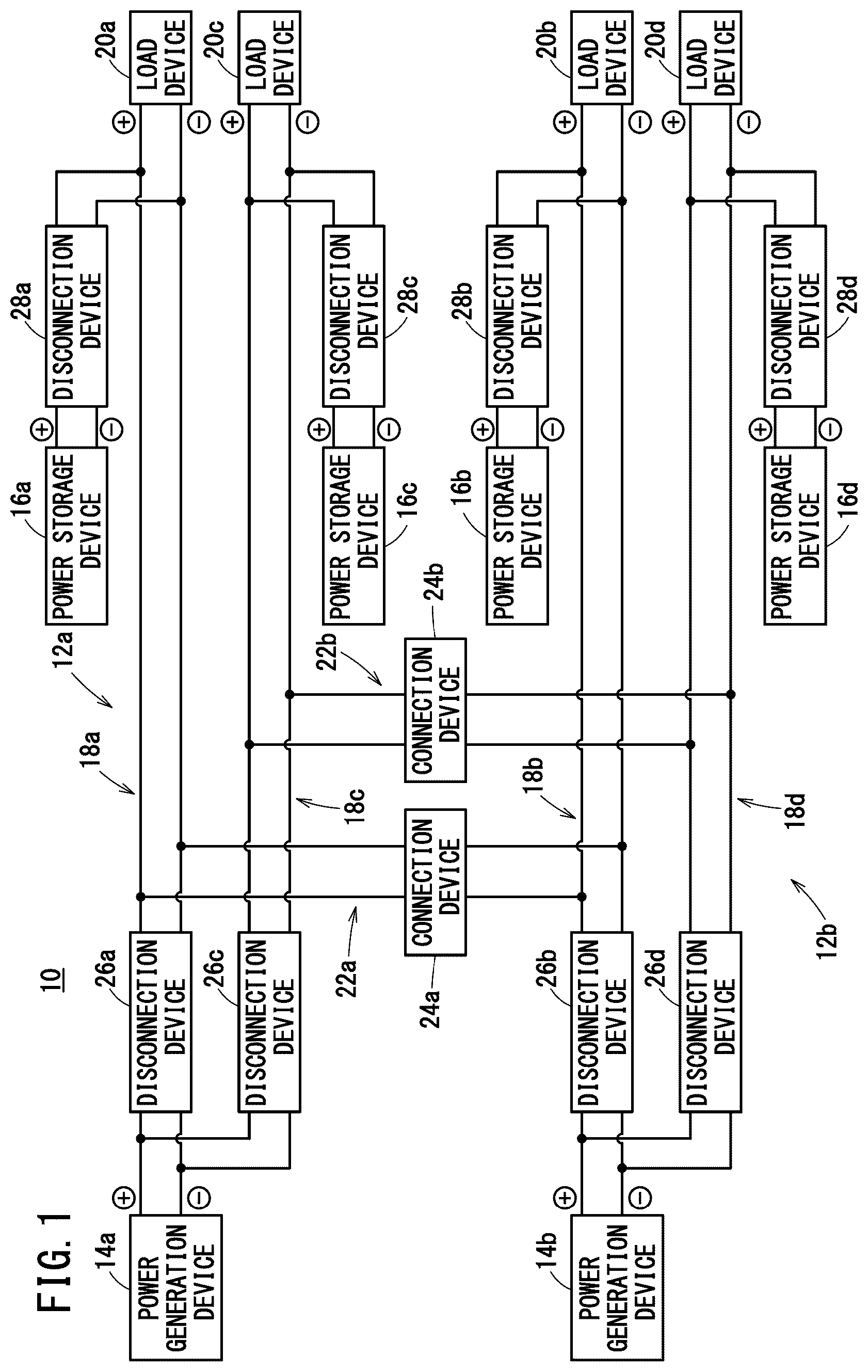
is a schematic diagram of a power supply system 10 according to a first embodiment. The power supply system 10 includes a first power supply subsystem 12 a and a second power supply subsystem 12 b . The first power supply subsystem 12 a includes a first power generation device 14 a serving as a main power source, and a first power storage device 16 a and a third power storage device 16 c serving as auxiliary power sources. The second power supply subsystem 12 b includes a second power generation device 14 b serving as a main power source, and a second power storage device 16 b and a fourth power storage device 16 d serving as auxiliary power sources.
The first power supply subsystem 12 a includes a first power supply circuit 18 a and a third power supply circuit 18 c . The first power supply circuit 18 a supplies, to a first load device 20 a , DC power output from the first power generation device 14 a . The third power supply circuit 18 c supplies, to a third load device 20 c , the DC power output from the first power generation device 14 a.
The second power supply subsystem 12 b includes a second power supply circuit 18 b and a fourth power supply circuit 18 d . The second power supply circuit 18 b supplies, to a second load device 20 b , DC power output from the second power generation device 14 b . The fourth power supply circuit 18 d supplies, to a fourth load device 20 d , the DC power output from the second power generation device 14 b.
The first power generation device 14 a and the second power generation device 14 b each include an engine, a generator, and a power control unit (all of them not shown). The engine drives the generator, and the generator generates three-phase AC power. The power control unit converts the three-phase AC power into DC power.
The first power generation device 14 a and the second power generation device 14 b may each include various sensors such as a voltage sensor and a current sensor, and elements such as a fuse, a relay, a breaker, a diode, a transistor, a resistor, a coil, and a capacitor.
The first load device 20 a , the second load device 20 b , the third load device 20 c , and the fourth load device 20 d each include an inverter and an electric motor (both of them not shown). The inverter converts the input DC power into three-phase AC power, and the electric motor is driven by the three-phase AC power. The first load device 20 a , the second load device 20 b , the third load device 20 c , and the fourth load device 20 d may each include a DC/DC converter and a low-voltage drive device (both of them not shown). The DC/DC converter steps down the voltage of the input DC power, and the low-voltage drive device is driven by the DC power whose voltage has been stepped down.
The first load device 20 a , the second load device 20 b , the third load device 20 c , and the fourth load device 20 d may each include various sensors such as a voltage sensor and a current sensor, and elements such as a fuse, a relay, a breaker, a diode, a transistor, a resistor, a coil, and a capacitor.
The power supply system 10 includes a first connection circuit 22 a and a second connection circuit 22 b . The first connection circuit 22 a includes a first connection device 24 a capable of connecting the first power supply circuit 18 a and the second power supply circuit 18 b . The second connection circuit 22 b includes a second connection device 24 b capable of connecting the third power supply circuit 18 c and the fourth power supply circuit 18 d.
The first connection device 24 a and the second connection device 24 b each include a contactor. The first connection device 24 a and the second connection device 24 b may each include a relay. The first connection device 24 a and the second connection device 24 b may each include a breaker. The first connection device 24 a and the second connection device 24 b may each include a semiconductor switch.
Normally, the first power supply circuit 18 a and the second power supply circuit 18 b are disconnected by the first connection device 24 a , and the third power supply circuit 18 c and the fourth power supply circuit 18 d are disconnected by the second connection device 24 b . That is, the first power supply subsystem 12 a and the second power supply subsystem 12 b are not connected to each other. Consequently, in a case where an abnormality occurs in one of the first power supply subsystem 12 a or the second power supply subsystem 12 b , the other can be prevented from being affected by the abnormality. For example, even when a short circuit occurs in the first power supply subsystem 12 a and the first load device 20 a and the third load device 20 c cannot be driven, the second load device 20 b and the fourth load device 20 d of the second power supply subsystem 12 b can continue to be driven.
In a case where the supply of electric power from the first power generation device 14 a to the first power supply circuit 18 a and the third power supply circuit 18 c is cut off, the first power supply circuit 18 a and the second power supply circuit 18 b are connected by the first connection device 24 a . Further, the third power supply circuit 18 c and the fourth power supply circuit 18 d are connected by the second connection device 24 b . As a result, electric power is supplied from the second power generation device 14 b to the first power supply circuit 18 a and the third power supply circuit 18 c.
In a case where the supply of electric power from the second power generation device 14 b to the second power supply circuit 18 b and the fourth power supply circuit 18 d is cut off, the first power supply circuit 18 a and the second power supply circuit 18 b are connected by the first connection device 24 a . Further, the third power supply circuit 18 c and the fourth power supply circuit 18 d are connected by the second connection device 24 b . As a result, electric power is supplied from the first power generation device 14 a to the second power supply circuit 18 b and the fourth power supply circuit 18 d.
The power supply system 10 includes disconnection devices 26 a to 26 d . The disconnection device 26 a can disconnect the first power generation device 14 a from the first power supply circuit 18 a and the first connection circuit 22 a . The disconnection device 26 b can disconnect the second power generation device 14 b from the second power supply circuit 18 b and the first connection circuit 22 a . The disconnection device 26 c can disconnect the first power generation device 14 a from the third power supply circuit 18 c and the second connection circuit 22 b . The disconnection device 26 d can disconnect the second power generation device 14 b from the fourth power supply circuit 18 d and the second connection circuit 22 b.
The disconnection devices 26 a to 26 d each include a contactor. The disconnection devices 26 a to 26 d may each include a relay. The disconnection devices 26 a to 26 d may each include a breaker. The disconnection devices 26 a to 26 d may each include a semiconductor switch.
The first power storage device 16 a is connected to the first power supply circuit 18 a in parallel with the first power generation device 14 a . The second power storage device 16 b is connected to the second power supply circuit 18 b in parallel with the second power generation device 14 b . The third power storage device 16 c is connected to the third power supply circuit 18 c in parallel with the first power generation device 14 a . The fourth power storage device 16 d is connected to the fourth power supply circuit 18 d in parallel with the second power generation device 14 b.
The first power storage device 16 a , the second power storage device 16 b , the third power storage device 16 c , and the fourth power storage device 16 d each include a lithium ion battery. The first power storage device 16 a , the second power storage device 16 b , the third power storage device 16 c , and the fourth power storage device 16 d may each include a secondary battery other than the lithium ion battery. The first power storage device 16 a , the second power storage device 16 b , the third power storage device 16 c , and the fourth power storage device 16 d may each include a large-capacity capacitor.
The first power storage device 16 a , the second power storage device 16 b , the third power storage device 16 c , and the fourth power storage device 16 d may each include various sensors such as a voltage sensor and a current sensor, and elements such as a fuse, a relay, a breaker, a diode, a transistor, a resistor, a coil, and a capacitor.
The power supply system 10 includes disconnection devices 28 a to 28 d . The disconnection device 28 a can disconnect the first power storage device 16 a from the first power supply circuit 18 a and the first load device 20 a . The disconnection device 28 b can disconnect the second power storage device 16 b from the second power supply circuit 18 b and the second load device 20 b . The disconnection device 28 c can disconnect the third power storage device 16 c from the third power supply circuit 18 c and the third load device 20 c . The disconnection device 28 d can disconnect the fourth power storage device 16 d from the fourth power supply circuit 18 d and the fourth load device 20 d.
The disconnection devices 28 a to 28 d each include a contactor. The disconnection devices 28 a to 28 d may each include a relay. The disconnection devices 28 a to 28 d may each include a breaker. The disconnection devices 28 a to 28 d may each include a semiconductor switch.
As shown in , the first load device 20 a and the third load device 20 c are connected in parallel. Further, the first power generation device 14 a and the first power storage device 16 a are connected in parallel. Furthermore, the first power generation device 14 a and the third power storage device 16 c are connected in parallel. Therefore, if the amount of voltage drop in the first power supply circuit 18 a and the third power supply circuit 18 c is considered to be sufficiently small, the output voltage of the first power generation device 14 a , the output voltage of the first power storage device 16 a , the output voltage of the third power storage device 16 c , the voltage applied to the first load device 20 a , and the voltage applied to the third load device 20 c are substantially equal to each other. Hereinafter, the output voltage of the first power generation device 14 a , the output voltage of the first power storage device 16 a , the output voltage of the third power storage device 16 c , the voltage applied to the first load device 20 a , and the voltage applied to the third load device 20 c may be collectively referred to as the voltage of the first power supply subsystem 12 a.
Similarly, the output voltage of the second power generation device 14 b , the output voltage of the second power storage device 16 b , the output voltage of the fourth power storage device 16 d , the voltage applied to the second load device 20 b , and the voltage applied to the fourth load device 20 d are substantially equal to each other. Hereinafter, the output voltage of the second power generation device 14 b , the output voltage of the second power storage device 16 b , the output voltage of the fourth power storage device 16 d , the voltage applied to the second load device 20 b , and the voltage applied to the fourth load device 20 d may be collectively referred to as the voltage of the second power supply subsystem 12 b.
[Operation of Power Supply System in Normal State]
is a diagram showing the operation of the power supply system 10 of the first embodiment in the normal state. Arrows shown in indicate electric power supply paths.
The connection between the first power supply circuit 18 a and the second power supply circuit 18 b is interrupted by the first connection device 24 a , and the connection between the third power supply circuit 18 c and the fourth power supply circuit 18 d is interrupted by the second connection device 24 b.
The first power generation device 14 a is connected to the first power supply circuit 18 a and the first connection circuit 22 a by the disconnection device 26 a , and the first power generation device 14 a is connected to the third power supply circuit 18 c and the second connection circuit 22 b by the disconnection device 26 c . As a result, electric power is supplied from the first power generation device 14 a to the first load device 20 a and the third load device 20 c.
The first power storage device 16 a is connected to the first load device 20 a by the disconnection device 28 a , and electric power is supplied from the first power storage device 16 a to the first load device 20 a . The third power storage device 16 c is connected to the third load device 20 c by the disconnection device 28 c , and electric power is supplied from the third power storage device 16 c to the third load device 20 c.
The second power generation device 14 b is connected to the second power supply circuit 18 b and the first connection circuit 22 a by the disconnection device 26 b , and the second power generation device 14 b is connected to the fourth power supply circuit 18 d and the second connection circuit 22 b by the disconnection device 26 d . As a result, electric power is supplied from the second power generation device 14 b to the second load device 20 b and the fourth load device 20 d.
The second power storage device 16 b is connected to the second load device 20 b by the disconnection device 28 b , and electric power is supplied from the second power storage device 16 b to the second load device 20 b . The fourth power storage device 16 d is connected to the fourth load device 20 d by the disconnection device 28 d , and electric power is supplied from the fourth power storage device 16 d to the fourth load device 20 d.
[Operation of Power Supply System in Event of Abnormality]
to 5 are diagrams showing the operation of the power supply system 10 of the first embodiment in the event of an abnormality. Arrows shown in to 5 indicate power supply paths. to 5 show the operation of the power supply system 10 in a case where the supply of electric power from the first power generation device 14 a to the first power supply circuit 18 a and the third power supply circuit 18 c is cut off.
The state in which the supply of electric power from the first power generation device 14 a to the first power supply circuit 18 a and the third power supply circuit 18 c is cut off is, for example, a state in which the first power generation device 14 a is stopped and cannot be restarted, or a state in which a short circuit, wire breaking (disconnection), or the like has occurred between the first power generation device 14 a and the disconnection device 26 a , and between the first power generation device 14 a and the disconnection device 26 c.
In a case where the supply of electric power from the first power generation device 14 a to the first power supply circuit 18 a and the third power supply circuit 18 c is cut off, then as shown in , the first power generation device 14 a is disconnected from the first power supply circuit 18 a and the first connection circuit 22 a by the disconnection device 26 a . Further, the first power generation device 14 a is disconnected from the third power supply circuit 18 c and the second connection circuit 22 b by the disconnection device 26 c.
In a case where there is a difference between the voltage of the first power supply subsystem 12 a and the voltage of the second power supply subsystem 12 b , then as shown in , the power supply system 10 of the first embodiment executes first power consumption suppression control on the first load device 20 a and the third load device 20 c , and executes first power consumption increase control on the second load device 20 b and the fourth load device 20 d.
The first power consumption suppression control and the first power consumption increase control are executed to approximate the voltage of the first power supply subsystem 12 a and the voltage of the second power supply subsystem 12 b . The first power consumption suppression control, the first power consumption increase control, and the approximating of the voltage of the first power supply subsystem 12 a and the voltage of the second power supply subsystem 12 b will be described in detail later.
After the voltage of the first power supply subsystem 12 a and the voltage of the second power supply subsystem 12 b are approximated to each other, the power supply system 10 of the first embodiment executes first connection control on the first connection device 24 a and executes second connection control on the second connection device 24 b , as shown in . As a result, the first power supply circuit 18 a and the second power supply circuit 18 b are connected by the first connection device 24 a , and the third power supply circuit 18 c and the fourth power supply circuit 18 d are connected by the second connection device 24 b . Therefore, electric power is supplied from the second power generation device 14 b to the first power supply circuit 18 a , and electric power is supplied from the second power generation device 14 b to the third power supply circuit 18 c.
[Configuration of Control Device]
The power supply system 10 includes a control device 30 . is a control block diagram of the control device 30 in the first embodiment.
The control device 30 includes a computation unit 32 and a storage unit 34 . The computation unit 32 is, for example, a processor such as a central processing unit (CPU) or a graphics processing unit (GPU). The computation unit 32 controls each device by executing a program stored in the storage unit 34 . At least part of the computation unit 32 may be realized by an integrated circuit such as an application specific integrated circuit (ASIC) or a field-programmable gate array (FPGA). At least part of the computation unit 32 may be realized by an electronic circuit including a discrete device.
The storage unit 34 is constituted by a volatile memory (not shown) and a non-volatile memory (not shown) which are computer-readable storage media. The volatile memory is, for example, a random access memory (RAM) or the like. The non-volatile memory is, for example, a read only memory (ROM), a flash memory, or the like. Data and the like are stored in, for example, the volatile memory. Programs, tables, maps, and the like are stored in, for example, the non-volatile memory. At least part of the storage unit 34 may be included in the processor, the integrated circuit, or the like described above.
The control device 30 controls the first load device 20 a , the second load device 20 b , the third load device 20 c , the fourth load device 20 d , the first connection device 24 a , the second connection device 24 b , the disconnection devices 26 a to 26 d , and the disconnection devices 28 a to 28 d . The first load device 20 a , the second load device 20 b , the third load device 20 c , the fourth load device 20 d , the first connection device 24 a , the second connection device 24 b , the disconnection devices 26 a to 26 d , and the disconnection devices 28 a to 28 d may be controlled by a plurality of the control devices 30 . For example, the first load device 20 a , the second load device 20 b , the third load device 20 c , and the fourth load device 20 d may be controlled by one control device 30 , and the first connection device 24 a , the second connection device 24 b , the disconnection devices 26 a to 26 d , and the disconnection devices 28 a to 28 d may be controlled by another control device 30 .
[Fail-Safe Control]
is a flowchart showing fail-safe control of the first embodiment. The fail-safe control is repeatedly executed at a predetermined cycle.
In step S 1 , the control device 30 determines whether or not the supply of electric power from the first power generation device 14 a to the first power supply circuit 18 a and the third power supply circuit 18 c has been cut off. In a case where it is determined that the supply of electric power from the first power generation device 14 a to the first power supply circuit 18 a and the third power supply circuit 18 c has been cut off (step S 1 : YES), the process proceeds to step S 2 .
In step S 2 , the control device 30 controls the disconnection device 26 a to disconnect the first power generation device 14 a from the first power supply circuit 18 a and the first connection circuit 22 a . Thereafter, the process proceeds to step S 3 .
In step S 3 , the control device 30 controls the disconnection device 26 c to disconnect the first power generation device 14 a from the third power supply circuit 18 c and the second connection circuit 22 b . Thereafter, the process proceeds to step S 4 .
In step S 4 , the control device 30 determines whether or not the difference between the voltage of the first power supply subsystem 12 a and the voltage of the second power supply subsystem 12 b is less than a first voltage threshold. In a case where it is determined that the difference between the voltage of the first power supply subsystem 12 a and the voltage of the second power supply subsystem 12 b is equal to or greater than the first voltage threshold (step S 4 : NO), the process proceeds to step S 5 . The first voltage threshold is determined in advance according to the magnitude of the current that each apparatus and each device of the power supply system 10 can withstand.
In step S 5 , the control device 30 executes the first power consumption suppression control on the first load device 20 a and the third load device 20 c . The first power consumption suppression control is control for suppressing the power consumption of the first load device 20 a and the power consumption of the third load device 20 c by reducing the required electric power of (electric power required by) the first load device 20 a and the required electric power of the third load device 20 c . Thereafter, the process proceeds to step S 6 .
In step S 6 , the control device 30 executes the first power consumption increase control on the second load device 20 b and the fourth load device 20 d . The first power consumption increase control is control for increasing the power consumption of the second load device 20 b and the power consumption of the fourth load device 20 d by increasing the required electric power of the second load device 20 b and the required electric power of the fourth load device 20 d . Thereafter, the process proceeds to step S 7 .
In step S 7 , the control device 30 determines whether or not the difference between the voltage of the first power supply subsystem 12 a and the voltage of the second power supply subsystem 12 b is equal to or less than a second voltage threshold. In a case where it is determined that the difference between the voltage of the first power supply subsystem 12 a and the voltage of the second power supply subsystem 12 b is greater than the second voltage threshold (step S 7 : NO), the process returns to step S 5 . The second voltage threshold is determined in advance according to the magnitude of the current that each apparatus and each device of the power supply system 10 can withstand. The second voltage threshold may be the same value as the first voltage threshold described above, or may be a value different from the first voltage threshold.
In a case where it is determined in the above-described step S 4 that the difference between the voltage of the first power supply subsystem 12 a and the voltage of the second power supply subsystem 12 b is less than the first voltage threshold (step S 4 : YES), or in a case where it is determined in the immediately preceding step S 7 that the difference between the voltage of the first power supply subsystem 12 a and the voltage of the second power supply subsystem 12 b is equal to or less than the second voltage threshold (step S 7 : YES), the process proceeds to step S 8 .
In step S 8 , the control device 30 executes the first connection control on the first connection device 24 a . As a result, the first power supply circuit 18 a and the second power supply circuit 18 b are connected via the first connection circuit 22 a . Thereafter, the process proceeds to step S 9 .
In step S 9 , the control device 30 executes the second connection control on the second connection device 24 b . As a result, the third power supply circuit 18 c and the fourth power supply circuit 18 d are connected via the second connection circuit 22 b . Thereafter, the fail-safe control is ended.
In the above-described step S 1 , in a case where it is determined that electric power is being supplied from the first power generation device 14 a to the first power supply circuit 18 a and the third power supply circuit 18 c (step S 1 : NO), the process proceeds to step S 10 .
In step S 10 , the control device 30 determines whether or not the supply of electric power from the second power generation device 14 b to the second power supply circuit 18 b and the fourth power supply circuit 18 d has been cut off. In a case where it is determined that the supply of electric power from the second power generation device 14 b to the second power supply circuit 18 b and the fourth power supply circuit 18 d has been cut off (step S 10 : YES), the process proceeds to step S 11 . In a case where it is determined that electric power is being supplied from the second power generation device 14 b to the second power supply circuit 18 b and the fourth power supply circuit 18 d (step S 10 : NO), the fail-safe control is ended.
In step S 11 , the control device 30 controls the disconnection device 26 b to disconnect the second power generation device 14 b from the second power supply circuit 18 b and the first connection circuit 22 a . Thereafter, the process proceeds to step S 12 .
In step S 12 , the control device 30 controls the disconnection device 26 d to disconnect the second power generation device 14 b from the fourth power supply circuit 18 d and the second connection circuit 22 b . Thereafter, the process proceeds to step S 13 .
In step S 13 , the control device 30 determines whether or not the difference between the voltage of the first power supply subsystem 12 a and the voltage of the second power supply subsystem 12 b is less than the first voltage threshold. In a case where it is determined that the difference between the voltage of the first power supply subsystem 12 a and the voltage of the second power supply subsystem 12 b is equal to or greater than the first voltage threshold (step S 13 : NO), the process proceeds to step S 14 .
In step S 14 , the control device 30 executes second power consumption suppression control on the second load device 20 b and the fourth load device 20 d . The second power consumption suppression control is control for suppressing the power consumption of the second load device 20 b and the power consumption of the fourth load device 20 d by reducing the required electric power of the second load device 20 b and the required electric power of the fourth load device 20 d . Thereafter, the process proceeds to step S 15 .
In step S 15 , the control device 30 executes second power consumption increase control on the first load device 20 a and the third load device 20 c . The second power consumption increase control is control for increasing the power consumption of the first load device 20 a and the power consumption of the third load device 20 c by increasing the required electric power of the first load device 20 a and the required electric power of the third load device 20 c . Thereafter, the process proceeds to step S 16 .
In step S 16 , the control device 30 determines whether or not the difference between the voltage of the first power supply subsystem 12 a and the voltage of the second power supply subsystem 12 b is equal to or less than the second voltage threshold. In a case where it is determined that the difference between the voltage of the first power supply subsystem 12 a and the voltage of the second power supply subsystem 12 b is greater than the second voltage threshold (step S 16 : NO), the process returns to step S 14 .
In a case where it is determined in the above-described step S 13 that the difference between the voltage of the first power supply subsystem 12 a and the voltage of the second power supply subsystem 12 b is less than the first voltage threshold (step S 13 : YES), or in a case where it is determined in the immediately preceding step S 16 that the difference between the voltage of the first power supply subsystem 12 a and the voltage of the second power supply subsystem 12 b is equal to or less than the second voltage threshold (step S 16 : YES), the process proceeds to step S 17 .
In step S 17 , the control device 30 executes the first connection control on the first connection device 24 a . As a result, the first power supply circuit 18 a and the second power supply circuit 18 b are connected via the first connection circuit 22 a . Thereafter, the process proceeds to step S 18 .
In step S 18 , the control device 30 executes the second connection control on the second connection device 24 b . As a result, the third power supply circuit 18 c and the fourth power supply circuit 18 d are connected via the second connection circuit 22 b . Thereafter, the fail-safe control is ended.
[Approximating of Voltage of First Power Supply Subsystem and Voltage of Second Power Supply Subsystem]
In the power supply system 10 of the first embodiment, in a case where there is a difference between the voltage of the first power supply subsystem 12 a and the voltage of the second power supply subsystem 12 b , the voltage of the first power supply subsystem 12 a and the voltage of the second power supply subsystem 12 b are approximated to each other before the first power supply subsystem 12 a and the second power supply subsystem 12 b are connected.
The following describes the state of the power supply system 10 in a case where the first power supply subsystem 12 a and the second power supply subsystem 12 b are connected in a state where there is a difference between the voltage of the first power supply subsystem 12 a and the voltage of the second power supply subsystem 12 b.
A to 8 C are graphs each showing a temporal change in the state of the power supply system 10 in periods before and after a time point at which the first power supply subsystem 12 a and the second power supply subsystem 12 b are connected. The graph of A shows a temporal change in the voltage of the first power supply subsystem 12 a and a temporal change in the voltage of the second power supply subsystem 12 b . The graph of B shows temporal changes in the required electric power of the first load device 20 a , the required electric power of the second load device 20 b , the required electric power of the third load device 20 c , and the required electric power of the fourth load device 20 d . The graph of C shows a temporal change in the current flowing through the first connection circuit 22 a and the second connection circuit 22 b . In each of the graphs of A to 8 C , temporal changes in the voltage, electric power, and current are schematically shown.
At a time point t 1 , the supply of electric power from the first power generation device 14 a is cut off, and at a time point t 2 , the first power supply circuit 18 a and the second power supply circuit 18 b are connected, and the third power supply circuit 18 c and the fourth power supply circuit 18 d are connected. In the periods indicated in the graphs of A to 8 C , the required electric power of the first load device 20 a , the required electric power of the second load device 20 b , the required electric power of the third load device 20 c , and the required electric power of the fourth load device 20 d are constant.
In the period before the time point t 1 , the output electric power of the first power generation device 14 a matches the sum of the required electric power of the first load device 20 a and the required electric power of the third load device 20 c , and the first power storage device 16 a and the third power storage device 16 c are not charged or discharged. Further, in the period before the time point t 1 , the output electric power of the second power generation device 14 b matches the sum of the required electric power of the second load device 20 b and the required electric power of the fourth load device 20 d , and the second power storage device 16 b and the fourth power storage device 16 d are not charged or discharged.
Since the supply of electric power from the first power generation device 14 a is cut off at the time point t 1 , the first power storage device 16 a and the third power storage device 16 c start discharging at the time point t 1 . The start of the discharge of the first power storage device 16 a increases the output electric power of the first power storage device 16 a , and increases the output current of the first power storage device 16 a . Therefore, the amount of voltage drop due to the internal resistance increases in the first power storage device 16 a , and the output voltage of the first power storage device 16 a decreases. In addition, the start of the discharge of the third power storage device 16 c increases the output electric power of the third power storage device 16 c , and increases the output current of the third power storage device 16 c . Therefore, the amount of voltage drop due to the internal resistance increases in the third power storage device 16 c , and the output voltage of the third power storage device 16 c decreases. That is, the voltage of the first power supply subsystem 12 a decreases (a portion indicated by a reference sign P in A ).
Further, in the period from the time point t 1 to the time point t 2 , electric power is supplied from the first power storage device 16 a to the first load device 20 a , and electric power is supplied from the third power storage device 16 c to the third load device 20 c . That is, in the period from the time point t 1 to the time point t 2 , the first power storage device 16 a and the third power storage device 16 c are discharged, and therefore, the state of charge (SOC) of the first power storage device 16 a and the SOC of the third power storage device 16 c gradually decrease. As the SOCs decrease, the open-end voltage of the first power storage device 16 a and the open-end voltage of the third power storage device 16 c decrease, and the output voltage of the first power storage device 16 a and the output voltage of the third power storage device 16 c gradually decrease. That is, the voltage of the first power supply subsystem 12 a gradually decreases (a portion indicated by a reference sign Q in A ).
On the other hand, in the period from the time point t 1 to the time point t 2 , electric power is supplied from the second power generation device 14 b to the second load device 20 b and the fourth load device 20 d . That is, in the period from the time point t 1 to the time point t 2 , the second power storage device 16 b and the fourth power storage device 16 d are not charged or discharged. Therefore, the output current of the second power storage device 16 b and the output current of the fourth power storage device 16 d do not change, and the amount of voltage drop due to the internal resistance does not change in the second power storage device 16 b and the fourth power storage device 16 d . Further, the SOC of the second power storage device 16 b and the SOC of the fourth power storage device 16 d are maintained. Therefore, the output voltage of the second power storage device 16 b and the output voltage of the fourth power storage device 16 d are maintained. That is, the voltage of the second power supply subsystem 12 b is maintained.
Since the voltage of the first power supply subsystem 12 a decreases and the voltage of the second power supply subsystem 12 b is maintained, the difference between the voltage of the first power supply subsystem 12 a and the voltage of the second power supply subsystem 12 b increases. Therefore, at the time point t 2 , when the first power supply circuit 18 a and the second power supply circuit 18 b are connected and the third power supply circuit 18 c and the fourth power supply circuit 18 d are connected, an overcurrent flows in the power supply system 10 . The overcurrent may damage each apparatus and each device of the power supply system 10 . In addition, in a case where each apparatus and each device of the power supply system 10 is designed to withstand an overcurrent, there is a problem in that the manufacturing cost of the power supply system 10 increases.
The following describes the state of the power supply system 10 in a case where the first power supply subsystem 12 a and the second power supply subsystem 12 b are connected after the voltage of the first power supply subsystem 12 a and the voltage of the second power supply subsystem 12 b are approximated to each other.
A to 9 C are graphs each showing a temporal change in the state of the power supply system 10 in periods before and after a time point at which the first power supply subsystem 12 a and the second power supply subsystem 12 b are connected. The graph of A shows a temporal change in the voltage of the first power supply subsystem 12 a and a temporal change in the voltage of the second power supply subsystem 12 b . The graph of B shows temporal changes in the required electric power of the first load device 20 a , the required electric power of the second load device 20 b , the required electric power of the third load device 20 c , and the required electric power of the fourth load device 20 d . The graph of C shows a temporal change in the current flowing through the first connection circuit 22 a and the second connection circuit 22 b . In each of the graphs of A to 9 C , temporal changes in the voltage, electric power, and current are schematically shown.
At a time point t 11 , the supply of electric power from the first power generation device 14 a is cut off, and at a time point t 12 , the first power consumption suppression control is executed on the first load device 20 a and the third load device 20 c , and the first power consumption increase control is executed on the second load device 20 b and the fourth load device 20 d.
In the period before the time point t 11 , the output electric power of the first power generation device 14 a matches the sum of the required electric power of the first load device 20 a and the required electric power of the third load device 20 c , and the first power storage device 16 a and the third power storage device 16 c are not charged or discharged. Further, in the period before the time point t 11 , the output electric power of the second power generation device 14 b matches the sum of the required electric power of the second load device 20 b and the required electric power of the fourth load device 20 d , and the second power storage device 16 b and the fourth power storage device 16 d are not charged or discharged.
Similarly to the period from the time point t 1 to the time point t 2 in A , in the period from the time point t 11 to the time point t 12 in A , the voltage of the first power supply subsystem 12 a decreases, and the voltage of the second power supply subsystem 12 b is maintained. Therefore, the difference between the voltage of the first power supply subsystem 12 a and the voltage of the second power supply subsystem 12 b increases.
In the power supply system 10 of the first embodiment, at the time point t 12 , the first power consumption suppression control is executed on the first load device 20 a and the third load device 20 c . The required electric power of the first load device 20 a and the required electric power of the third load device 20 c are gradually reduced by the first power consumption suppression control. As a result, the output electric power of the first power storage device 16 a and the output electric power of the third power storage device 16 c gradually decrease, and the output current of the first power storage device 16 a and the output current of the third power storage device 16 c gradually decrease. Therefore, the amount of voltage drop due to the internal resistance gradually decreases in the first power storage device 16 a and the third power storage device 16 c . Further, compared to the period from the time point t 11 to the time point t 12 , the required electric power of the first load device 20 a and the required electric power of the third load device 20 c are reduced in the period from the time point t 12 to a time point t 13 , and therefore, the decrease in the SOC of the first power storage device 16 a and the decrease in the SOC of the third power storage device 16 c are suppressed.
As described above, the first power consumption suppression control reduces the amount of voltage drop due to the internal resistance in the first power storage device 16 a and the third power storage device 16 c , and also suppresses the decrease in the SOC of the first power storage device 16 a and the decrease in the SOC of the third power storage device 16 c to thereby suppress the decrease in the output voltage of the first power storage device 16 a and the decrease in the output voltage of the third power storage device 16 c . That is, the decrease in the voltage of the first power supply subsystem 12 a is suppressed.
In addition, in the power supply system 10 of the first embodiment, the first power consumption increase control is executed on the second load device 20 b and the fourth load device 20 d at the time point t 12 . The required electric power of the second load device 20 b and the required electric power of the fourth load device 20 d are gradually increased by the first power consumption increase control.
In accordance with the increase in the required electric power of the second load device 20 b and the required electric power of the fourth load device 20 d , the second power generation device 14 b is controlled to increase its output electric power. However, since the response speed of the output electric power of the second power generation device 14 b is relatively slow, the output electric power of the second power generation device 14 b is insufficient for the required electric power of the second load device 20 b and the required electric power of the fourth load device 20 d for a while after the required electric power of the second load device 20 b and the required electric power of the fourth load device 20 d are increased.
The electric power corresponding to the shortage is supplied from the second power storage device 16 b to the second load device 20 b , and is supplied from the fourth power storage device 16 d to the fourth load device 20 d . As the required electric power of the second load device 20 b gradually increases, the output electric power of the second power storage device 16 b gradually increases, and the output current of the second power storage device 16 b gradually increases. Therefore, the amount of voltage drop due to the internal resistance gradually increases in the second power storage device 16 b . Further, as the required electric power of the fourth load device 20 d gradually increases, the output electric power of the fourth power storage device 16 d gradually increases, and the output current of the fourth power storage device 16 d gradually increases. Therefore, the amount of voltage drop due to the internal resistance gradually increases in the fourth power storage device 16 d.
In addition, in the period from the time point t 12 to the time point t 13 , the second power storage device 16 b and the fourth power storage device 16 d are discharged, and therefore, the decrease in the SOC of the second power storage device 16 b and the decrease in the SOC of the fourth power storage device 16 d are promoted.
As described above, the first power consumption increase control gradually increases the amount of voltage drop due to the internal resistance in the second power storage device 16 b and the fourth power storage device 16 d , and also promotes the decrease in the SOC of the second power storage device 16 b and the decrease in the SOC of the fourth power storage device 16 d to thereby promote the decrease in the output voltage of the second power storage device 16 b and the decrease in the output voltage of the fourth power storage device 16 d . That is, the decrease in the voltage of the second power supply subsystem 12 b is promoted.
By promoting the decrease in the voltage of the second power supply subsystem 12 b and suppressing the decrease in the voltage of the first power supply subsystem 12 a , the voltage of the second power supply subsystem 12 b can be approximated to the voltage of the first power supply subsystem 12 a . At the time point t 13 at which the voltage of the first power supply subsystem 12 a and the voltage of the second power supply subsystem 12 b are approximate to each other, the first power supply circuit 18 a and the second power supply circuit 18 b are connected, and the third power supply circuit 18 c and the fourth power supply circuit 18 d are connected. As a result, it is possible to prevent an overcurrent from flowing in the power supply system 10 . Therefore, damage to each apparatus and each device of the power supply system 10 is suppressed. Further, it is not necessary to design each apparatus and each device of the power supply system 10 to withstand an overcurrent, and therefore, it is possible to suppress the manufacturing cost of the power supply system 10 .
It should be noted that, in a case where the first power consumption suppression control is executed on the first load device 20 a and the third load device 20 c , the output of the first load device 20 a and the output of the third load device 20 c decrease. On the other hand, in a case where the first power consumption increase control is executed on the second load device 20 b and the fourth load device 20 d , the output of the second load device 20 b and the output of the fourth load device 20 d increase. As a result, the output of the whole of the first load device 20 a , the second load device 20 b , the third load device 20 c , and the fourth load device 20 d is maintained.
The case where the supply of electric power from the first power generation device 14 a is cut off has been described above, and also in a case where the supply of electric power from the second power generation device 14 b is cut off, the first power supply subsystem 12 a and the second power supply subsystem 12 b are connected after the voltage of the first power supply subsystem 12 a and the voltage of the second power supply subsystem 12 b are approximated to each other.
In a case where the supply of electric power from the second power generation device 14 b has been cut off, the second power consumption suppression control is executed on the second load device 20 b and the fourth load device 20 d , and the second power consumption increase control is executed on the first load device 20 a and the third load device 20 c . As a result, the voltage of the first power supply subsystem 12 a and the voltage of the second power supply subsystem 12 b are approximated to each other.
[Comparison with Power Supply System of Comparative Example]
is a schematic diagram of a power supply system 100 according to a comparative example. The power supply system 100 of the comparative example includes voltage conversion devices 30 a to 30 d . The voltage conversion devices 30 a to 30 d are DC/DC converters.
In the power supply system 100 , the output voltages of the voltage conversion devices 30 a to 30 d are substantially equalized. Therefore, when the first power supply circuit 18 a and the second power supply circuit 18 b are connected by the first connection device 24 a , it is possible to prevent an overcurrent from flowing through the first power supply circuit 18 a and the second power supply circuit 18 b . Similarly, when the third power supply circuit 18 c and the fourth power supply circuit 18 d are connected by the second connection device 24 b , it is possible to prevent an overcurrent from flowing through the third power supply circuit 18 c and the fourth power supply circuit 18 d.
However, since the power supply system 100 includes the voltage conversion devices 30 a to 30 d , there are problems in that the number of components constituting the power supply system 100 increases, the weight of the power supply system 100 increases, and the manufacturing cost of the power supply system 100 increases. The power supply system 10 of the first embodiment does not include the voltage conversion devices 30 a to 30 d , and therefore, it is possible to reduce the number of components constituting the power supply system 10 , to achieve a reduction in the weight of the power supply system 10 , and to suppress the manufacturing cost of the power supply system 10 .
Second Embodiment
The configuration of the power supply system 10 of a second embodiment is the same as the configuration of the power supply system 10 of the first embodiment. However, the fail-safe control executed by the control device 30 of the second embodiment is partially different from the fail-safe control executed by the control device 30 of the first embodiment.
[Operation of Power Supply System in Event of Abnormality]
to 13 are diagrams showing the operation of the power supply system 10 of the second embodiment in the event of an abnormality. Arrows shown in to 13 indicate electric power supply paths. to 13 show the operation of the power supply system 10 in a case where the supply of electric power from the first power generation device 14 a to the first load device 20 a is stopped.
The state in which the supply of electric power from the first power generation device 14 a to the first load device 20 a is stopped is, for example, a state in which the first load device 20 a is stopped and cannot be restarted, or a state in which a short circuit, wire breaking (disconnection), or the like has occurred between the disconnection device 26 a and the first load device 20 a.
In a case where the supply of electric power from the first power generation device 14 a to the first load device 20 a is stopped, then as shown in , the first power generation device 14 a is disconnected from the first power supply circuit 18 a and the first connection circuit 22 a by the disconnection device 26 a.
In a case where there is a difference between the voltage of the first power supply subsystem 12 a and the voltage of the second power supply subsystem 12 b , then as shown in , the power supply system 10 of the second embodiment executes second power consumption suppression control on the second load device 20 b and the fourth load device 20 d , and executes second power consumption increase control on the third load device 20 c.
The second power consumption suppression control and the second power consumption increase control are executed to approximate the voltage of the first power supply subsystem 12 a and the voltage of the second power supply subsystem 12 b . The second power consumption suppression control, the second power consumption increase control, and the approximating of the voltage of the first power supply subsystem 12 a and the voltage of the second power supply subsystem 12 b will be described in detail later.
After the voltage of the first power supply subsystem 12 a and the voltage of the second power supply subsystem 12 b are approximated to each other, second connection control is executed on the second connection device 24 b . As shown in , the third power supply circuit 18 c and the fourth power supply circuit 18 d are connected by the second connection device 24 b . As a result, electric power is supplied from the first power generation device 14 a to the fourth power supply circuit 18 d.
[Fail-Safe Control]
are flowcharts showing the fail-safe control. The fail-safe control is repeatedly executed at a predetermined cycle.
In step S 21 , the control device 30 determines whether or not the supply of electric power from the first power generation device 14 a to the first load device 20 a has been stopped. In a case where it is determined that the supply of electric power from the first power generation device 14 a to the first load device 20 a has been stopped (step S 21 : YES), the process proceeds to step S 22 .
In step S 22 , the control device 30 controls the disconnection device 26 a to disconnect the first power generation device 14 a from the first power supply circuit 18 a and the first connection circuit 22 a . Thereafter, the process proceeds to step S 23 .
In step S 23 , the control device 30 determines whether or not the difference between the voltage of the first power supply subsystem 12 a and the voltage of the second power supply subsystem 12 b is less than a first voltage threshold. In a case where it is determined that the difference between the voltage of the first power supply subsystem 12 a and the voltage of the second power supply subsystem 12 b is equal to or greater than the first voltage threshold (step S 23 : NO), the process proceeds to step S 24 .
In step S 24 , the control device 30 executes second power consumption suppression control on the second load device 20 b and the fourth load device 20 d . The second power consumption suppression control is control for suppressing the power consumption of the second load device 20 b and the power consumption of the fourth load device 20 d by reducing the required electric power of the second load device 20 b and the required electric power of the fourth load device 20 d . Thereafter, the process proceeds to step S 25 .
In step S 25 , the control device 30 executes second power consumption increase control on the third load device 20 c . The second power consumption increase control is control for increasing the power consumption of the third load device 20 c by increasing the required electric power of the third load device 20 c . Thereafter, the process proceeds to step S 26 .
In step S 26 , the control device 30 determines whether or not the difference between the voltage of the first power supply subsystem 12 a and the voltage of the second power supply subsystem 12 b is equal to or less than a second voltage threshold. In a case where it is determined that the difference between the voltage of the first power supply subsystem 12 a and the voltage of the second power supply subsystem 12 b is greater than the second voltage threshold (step S 26 : NO), the process returns to step S 24 .
In a case where it is determined in the above-described step S 23 that the difference between the voltage of the first power supply subsystem 12 a and the voltage of the second power supply subsystem 12 b is less than the first voltage threshold (step S 23 : YES), or in a case where it is determined in the immediately preceding step S 26 that the difference between the voltage of the first power supply subsystem 12 a and the voltage of the second power supply subsystem 12 b is equal to or less than the second voltage threshold (step S 26 : YES), the process proceeds to step S 27 .
In step S 27 , the control device 30 executes the second connection control on the second connection device 24 b . As a result, the third power supply circuit 18 c and the fourth power supply circuit 18 d are connected via the second connection circuit 22 b . Thereafter, the fail-safe control is ended.
In the above-described step S 21 , in a case where it is determined that electric power is being supplied from the first power generation device 14 a to the first load device 20 a (step S 21 : NO), the process proceeds to step S 28 .
In step S 28 , the control device 30 determines whether or not the supply of electric power from the second power generation device 14 b to the second load device 20 b has been stopped. In a case where it is determined that the supply of electric power from the second power generation device 14 b to the second load device 20 b has been stopped (step S 28 : YES), the process proceeds to step S 29 .
In step S 29 , the control device 30 controls the disconnection device 26 b to disconnect the second power generation device 14 b from the second power supply circuit 18 b and the first connection circuit 22 a . Thereafter, the process proceeds to step S 30 .
In step S 30 , the control device 30 determines whether or not the difference between the voltage of the first power supply subsystem 12 a and the voltage of the second power supply subsystem 12 b is less than the first voltage threshold. In a case where it is determined that the difference between the voltage of the first power supply subsystem 12 a and the voltage of the second power supply subsystem 12 b is equal to or greater than the first voltage threshold (step S 30 : NO), the process proceeds to step S 31 .
In step S 31 , the control device 30 executes first power consumption suppression control on the first load device 20 a and the third load device 20 c . The first power consumption suppression control is control for suppressing the power consumption of the first load device 20 a and the power consumption of the third load device 20 c by reducing the required electric power of the first load device 20 a and the required electric power of the third load device 20 c . Thereafter, the process proceeds to step S 32 .
In step S 32 , the control device 30 executes first power consumption increase control on the fourth load device 20 d . The first power consumption increase control is control for increasing the power consumption of the fourth load device 20 d by increasing the required electric power of the fourth load device 20 d . Thereafter, the process proceeds to step S 33 .
In step S 33 , the control device 30 determines whether or not the difference between the voltage of the first power supply subsystem 12 a and the voltage of the second power supply subsystem 12 b is equal to or less than the second voltage threshold. In a case where it is determined that the difference between the voltage of the first power supply subsystem 12 a and the voltage of the second power supply subsystem 12 b is greater than the second voltage threshold (step S 33 : NO), the process returns to step S 31 .
In a case where it is determined in the above-described step S 30 that the difference between the voltage of the first power supply subsystem 12 a and the voltage of the second power supply subsystem 12 b is less than the first voltage threshold (step S 30 : YES), or in a case where it is determined in the immediately preceding step S 33 that the difference between the voltage of the first power supply subsystem 12 a and the voltage of the second power supply subsystem 12 b is equal to or less than the second voltage threshold (step S 33 : YES), the process proceeds to step S 34 .
In step S 34 , the control device 30 executes the second connection control on the second connection device 24 b . As a result, the third power supply circuit 18 c and the fourth power supply circuit 18 d are connected via the second connection circuit 22 b . Thereafter, the fail-safe control is ended.
In the above-described step S 28 , in a case where it is determined that electric power is being supplied from the second power generation device 14 b to the second load device 20 b (step S 28 : NO), the process proceeds to step S 35 .
In step S 35 , the control device 30 determines whether or not the supply of electric power from the first power generation device 14 a to the third load device 20 c has been stopped. In a case where it is determined that the supply of electric power from the first power generation device 14 a to the third load device 20 c has been stopped (step S 35 : YES), the process proceeds to step S 36 .
In step S 36 , the control device 30 controls the disconnection device 26 c to disconnect the first power generation device 14 a from the third power supply circuit 18 c and the second connection circuit 22 b . Thereafter, the process proceeds to step S 37 .
In step S 37 , the control device 30 determines whether or not the difference between the voltage of the first power supply subsystem 12 a and the voltage of the second power supply subsystem 12 b is less than the first voltage threshold. In a case where it is determined that the difference between the voltage of the first power supply subsystem 12 a and the voltage of the second power supply subsystem 12 b is equal to or greater than the first voltage threshold (step S 37 : NO), the process proceeds to step S 38 .
In step S 38 , the control device 30 executes the second power consumption suppression control on the second load device 20 b and the fourth load device 20 d . Thereafter, the process proceeds to step S 39 .
In step S 39 , the control device 30 executes the second power consumption increase control on the first load device 20 a . Thereafter, the process proceeds to step S 40 .
In step S 40 , the control device 30 determines whether or not the difference between the voltage of the first power supply subsystem 12 a and the voltage of the second power supply subsystem 12 b is equal to or less than the second voltage threshold. In a case where it is determined that the difference between the voltage of the first power supply subsystem 12 a and the voltage of the second power supply subsystem 12 b is greater than the second voltage threshold (step S 40 : NO), the process returns to step S 38 .
In a case where it is determined in the above-described step S 37 that the difference between the voltage of the first power supply subsystem 12 a and the voltage of the second power supply subsystem 12 b is less than the first voltage threshold (step S 37 : YES), or in a case where it is determined in the immediately preceding step S 40 that the difference between the voltage of the first power supply subsystem 12 a and the voltage of the second power supply subsystem 12 b is equal to or less than the second voltage threshold (step S 40 : YES), the process proceeds to step S 41 .
In step S 41 , the control device 30 executes first connection control on the first connection device 24 a . As a result, the first power supply circuit 18 a and the second power supply circuit 18 b are connected via the first connection circuit 22 a . Thereafter, the fail-safe control is ended.
In the above-described step S 35 , in a case where it is determined that electric power is being supplied from the first power generation device 14 a to the third load device 20 c (step S 35 : NO), the process proceeds to step S 42 .
In step S 42 , the control device 30 determines whether or not the supply of electric power from the second power generation device 14 b to the fourth load device 20 d has been stopped. In a case where it is determined that the supply of electric power from the second power generation device 14 b to the fourth load device 20 d has been stopped (step S 42 : YES), the process proceeds to step S 43 . In a case where it is determined that electric power is being supplied from the second power generation device 14 b to the fourth load device 20 d (step S 42 : NO), the fail-safe control is ended.
In step S 43 , the control device 30 controls the disconnection device 26 d to disconnect the second power generation device 14 b from the fourth power supply circuit 18 d and the second connection circuit 22 b . Thereafter, the process proceeds to step S 44 .
In step S 44 , the control device 30 determines whether or not the difference between the voltage of the first power supply subsystem 12 a and the voltage of the second power supply subsystem 12 b is less than the first voltage threshold. In a case where it is determined that the difference between the voltage of the first power supply subsystem 12 a and the voltage of the second power supply subsystem 12 b is equal to or greater than the first voltage threshold (step S 44 : NO), the process proceeds to step S 45 .
In step S 45 , the control device 30 executes the first power consumption suppression control on the first load device 20 a and the third load device 20 c . Thereafter, the process proceeds to step S 46 .
In step S 46 , the control device 30 executes the first power consumption increase control on the second load device 20 b . Thereafter, the process proceeds to step S 47 .
In step S 47 , the control device 30 determines whether or not the difference between the voltage of the first power supply subsystem 12 a and the voltage of the second power supply subsystem 12 b is equal to or less than the second voltage threshold. In a case where it is determined that the difference between the voltage of the first power supply subsystem 12 a and the voltage of the second power supply subsystem 12 b is greater than the second voltage threshold (step S 47 : NO), the process returns to step S 45 .
In a case where it is determined in the above-described step S 44 that the difference between the voltage of the first power supply subsystem 12 a and the voltage of the second power supply subsystem 12 b is less than the first voltage threshold (step S 44 : YES), or in a case where it is determined in the immediately preceding step S 47 that the difference between the voltage of the first power supply subsystem 12 a and the voltage of the second power supply subsystem 12 b is equal to or less than the second voltage threshold (step S 47 : YES), the process proceeds to step S 48 .
In step S 48 , the control device 30 executes the first connection control on the first connection device 24 a . As a result, the first power supply circuit 18 a and the second power supply circuit 18 b are connected via the first connection circuit 22 a . Thereafter, the fail-safe control is ended.
A to 16 C are graphs each showing a temporal change in the state of the power supply system 10 in periods before and after a time point at which the first power supply subsystem 12 a and the second power supply subsystem 12 b are connected. The graph of A shows a temporal change in the voltage of the first power supply subsystem 12 a and a temporal change in the voltage of the second power supply subsystem 12 b . The graph of B shows temporal changes in the required electric power of the first load device 20 a , the required electric power of the second load device 20 b , the required electric power of the third load device 20 c , and the required electric power of the fourth load device 20 d . The graph of C shows a temporal change in the current flowing through the first connection circuit 22 a and the second connection circuit 22 b . In each of the graphs of A to 16 C , temporal changes in the voltage, electric power, and current are schematically shown.
At a time point t 21 , the supply of electric power to the first load device 20 a is stopped, and at a time point t 22 , the second power consumption suppression control is executed on the second load device 20 b and the fourth load device 20 d , and the second power consumption increase control is executed on the third load device 20 c.
In the period before the time point t 21 , the output electric power of the first power generation device 14 a matches the sum of the required electric power of the first load device 20 a and the required electric power of the third load device 20 c , and the first power storage device 16 a and the third power storage device 16 c are not charged or discharged. Further, in the period before the time point t 21 , the output electric power of the second power generation device 14 b matches the sum of the required electric power of the second load device 20 b and the required electric power of the fourth load device 20 d , and the second power storage device 16 b and the fourth power storage device 16 d are not charged or discharged.
At the time point t 21 , the output of the first load device 20 a becomes 0 (zero), and therefore, the output of the second load device 20 b , the output of the third load device 20 c , and the output of the fourth load device 20 d increase in order to maintain the overall output. Therefore, at the time point t 21 , the required electric power of the second load device 20 b , the required electric power of the third load device 20 c , and the required electric power of the fourth load device 20 d increase.
At the time point t 21 , the required electric power of the third load device 20 c increases, but the required electric power of the first load device 20 a is 0 (zero), and the sum of the required electric power of the first load device 20 a and the required electric power of the third load device 20 c is smaller than the output electric power of the first power generation device 14 a . Therefore, the first power generation device 14 a is controlled to reduce its output electric power. However, since the response speed of the output electric power of the first power generation device 14 a is relatively slow, the output electric power of the first power generation device 14 a is surplus with respect to the required electric power of the third load device 20 c for a while after the required electric power of the first load device 20 a becomes 0 (zero).
At the time point t 21 , charging of the third power storage device 16 c with the surplus electric power is started. Since electric power is input to the third power storage device 16 c , an input current is generated in the third power storage device 16 c , and a voltage rise due to the internal resistance occurs in the third power storage device 16 c . Therefore, the output voltage of the third power storage device 16 c increases. That is, the voltage of the first power supply subsystem 12 a increases (a portion indicated by a reference sign R in A ).
Further, in the period from the time point t 21 to the time point t 22 , the charging of the third power storage device 16 c is continued, and therefore, the SOC of the third power storage device 16 c gradually increases, and the output voltage of the third power storage device 16 c gradually increases. That is, the voltage of the first power supply subsystem 12 a gradually increases (a portion indicated by a reference sign S in A ).
In accordance with the increase in the required electric power of the second load device 20 b and the required electric power of the fourth load device 20 d at the time point t 21 , the second power generation device 14 b is controlled to increase its output electric power. However, since the response speed of the output electric power of the second power generation device 14 b is relatively slow, the output electric power of the second power generation device 14 b is insufficient for the required electric power of the second load device 20 b and the required electric power of the fourth load device 20 d for a while after the required electric power of the second load device 20 b and the required electric power of the fourth load device 20 d are increased.
The electric power corresponding to the shortage is supplied from the second power storage device 16 b to the second load device 20 b , and is supplied from the fourth power storage device 16 d to the fourth load device 20 d . That is, at the time point t 21 , the second power storage device 16 b and the fourth power storage device 16 d start discharging. The start of the discharge of the second power storage device 16 b increases the output electric power of the second power storage device 16 b , and increases the output current of the second power storage device 16 b . Therefore, the amount of voltage drop due to the internal resistance increases in the second power storage device 16 b , and the output voltage of the second power storage device 16 b decreases. In addition, the start of the discharge of the fourth power storage device 16 d increases the output electric power of the fourth power storage device 16 d , and increases the output current of the fourth power storage device 16 d . Therefore, the amount of voltage drop due to the internal resistance increases in the fourth power storage device 16 d , and the output voltage of the fourth power storage device 16 d decreases. That is, the voltage of the second power supply subsystem 12 b decreases (a portion indicated by a reference sign T in A ).
Further, in the period from the time point t 21 to the time point t 22 , the second power storage device 16 b and the fourth power storage device 16 d are discharged, and therefore, the SOC of the second power storage device 16 b and the SOC of the fourth power storage device 16 d gradually decrease. As the SOCs decrease, the open-end voltage of the second power storage device 16 b and the open-end voltage of the fourth power storage device 16 d decrease, and the output voltage of the second power storage device 16 b and the output voltage of the fourth power storage device 16 d gradually decrease. That is, the voltage of the second power supply subsystem 12 b gradually decreases (a portion indicated by a reference sign U in A ).
Since the voltage of the first power supply subsystem 12 a increases and the voltage of the second power supply subsystem 12 b decreases, the difference between the voltage of the first power supply subsystem 12 a and the voltage of the second power supply subsystem 12 b increases.
In the power supply system 10 of the second embodiment, at the time point t 22 , the second power consumption suppression control is executed on the second load device 20 b and the fourth load device 20 d . The required electric power of the second load device 20 b and the required electric power of the fourth load device 20 d are gradually reduced by the second power consumption suppression control. As a result, the output electric power of the second power storage device 16 b and the output electric power of the fourth power storage device 16 d gradually decrease, and the output current of the second power storage device 16 b and the output current of the fourth power storage device 16 d gradually decrease. Therefore, the amount of voltage drop due to the internal resistance gradually decreases in the second power storage device 16 b and the fourth power storage device 16 d . As a result, the output voltage of the second power storage device 16 b and the output voltage of the fourth power storage device 16 d gradually increase. Further, compared to the period from the time point t 21 to the time point t 22 , the required electric power of the second load device 20 b and the required electric power of the fourth load device 20 d are reduced in the period from the time point t 22 to a time point t 23 , and therefore, the decrease in the SOC of the second power storage device 16 b and the decrease in the SOC of the fourth power storage device 16 d are suppressed.
As described above, the second power consumption suppression control reduces the amount of voltage drop due to the internal resistance in the second power storage device 16 b and the fourth power storage device 16 d , and also suppresses the decrease in the SOC of the second power storage device 16 b and the decrease in the SOC of the fourth power storage device 16 d to thereby suppress the decrease in the output voltage of the second power storage device 16 b and the decrease in the output voltage of the fourth power storage device 16 d . Therefore, the decrease in the voltage of the second power supply subsystem 12 b is suppressed.
Further, in the power supply system 10 of the second embodiment, the second power consumption increase control is executed on the third load device 20 c at the time point t 22 . The required electric power of the third load device 20 c is gradually increased by the second power consumption increase control. When the required electric power of the third load device 20 c becomes larger than the output electric power of the first power generation device 14 a , the electric power corresponding to the shortage is supplied from the third power storage device 16 c to the third load device 20 c . As the required electric power of the third load device 20 c gradually increases, the output electric power of the third power storage device 16 c gradually increases, and the output current of the third power storage device 16 c gradually increases. Therefore, the amount of voltage drop due to the internal resistance gradually increases in the third power storage device 16 c.
Further, in the period from time point t 22 to the time point t 23 , the third power storage device 16 c is discharged, and therefore, the decrease in the SOC of the third power storage device 16 c is promoted.
As described above, the second power consumption increase control increases the amount of voltage drop due to the internal resistance in the third power storage device 16 c , and also promotes the decrease in the SOC of the third power storage device 16 c to thereby promote the decrease in the output voltage of the third power storage device 16 c . That is, the decrease in the voltage of the first power supply subsystem 12 a is promoted.
By promoting the decrease in the voltage of the first power supply subsystem 12 a and suppressing the decrease in the voltage of the second power supply subsystem 12 b , the voltage of the first power supply subsystem 12 a can be approximated to the voltage of the second power supply subsystem 12 b . At the time point t 23 at which the voltage of the first power supply subsystem 12 a and the voltage of the second power supply subsystem 12 b are approximate to each other, the third power supply circuit 18 c and the fourth power supply circuit 18 d are connected, and therefore, it is possible to prevent an overcurrent from flowing in the power supply system 10 . Therefore, damage to each apparatus and each device of the power supply system 10 is suppressed. Further, it is not necessary to design each apparatus and each device of the power supply system 10 to withstand an overcurrent, and therefore, it is possible to suppress the manufacturing cost of the power supply system 10 .
Third Embodiment
[Configuration of Moving Object]
is a schematic view of a moving object 44 . The power supply system 10 is mounted on the moving object 44 .
The moving object 44 of the present embodiment is an electric vertical take-off and landing aircraft (eVTOL aircraft). The moving object 44 includes eight VTOL rotors 46 . The VTOL rotors 46 generate upward thrust for a fuselage 48 . The moving object 44 includes eight electric motors 50 . One electric motor 50 drives one VTOL rotor 46 . The moving object 44 includes two cruise rotors 52 . The cruise rotors 52 generate forward thrust for the fuselage 48 . The moving object 44 includes four electric motors 54 . Two electric motors 54 drive one cruise rotor 52 .
Each of the first load device 20 a , the second load device 20 b , the third load device 20 c , and the fourth load device 20 d may include two electric motors 50 and one electric motor 54 . Each of the first load device 20 a , the second load device 20 b , the third load device 20 c , and the fourth load device 20 d may include a low-voltage drive device in addition to the electric motors 50 and the electric motor 54 .
The moving object 44 is not limited to an aircraft, and may be a ship, an automobile, a train, or the like.
The following supplementary notes are further disclosed in relation to the above-described embodiments.
Supplementary Note 1
The power supply system ( 10 ) of the present disclosure includes: the first power supply circuit ( 18 a ) configured to supply, to the first load device ( 20 a ), electric power output from the first power generation device ( 14 a ), the electric power being DC power; the first power storage device ( 16 a ) connected to the first power supply circuit in parallel with the first power generation device; the second power supply circuit ( 18 b ) configured to supply, to the second load device ( 20 b ), electric power output from the second power generation device ( 14 b ), the electric power being DC power; the second power storage device ( 16 b ) connected to the second power supply circuit in parallel with the second power generation device; the first connection circuit ( 22 a ) including the first connection device ( 24 a ) configured to connect the first power supply circuit and the second power supply circuit to each other; and the control device ( 30 ) configured to execute, on the first connection device, first connection control for connecting the first power supply circuit and the second power supply circuit to each other via the first connection circuit, wherein, in a case where the electric power output from the second power generation device is required to be supplied to the first load device and a difference between the voltage of the first power supply circuit and the voltage of the second power supply circuit is equal to or greater than the first voltage threshold determined in advance, the control device executes the first connection control on the first connection device after executing first power consumption suppression control on the first load device and executing first power consumption increase control on the second load device, the first power consumption suppression control being control for suppressing the power consumption of the first load device to suppress a decrease in the output voltage of the first power storage device, the first power consumption increase control being control for increasing the power consumption of the second load device to promote a decrease in the output voltage of the second power storage device. According to this feature, it is possible to prevent an overcurrent from flowing in the power supply system.
Supplementary Note 2
In the power supply system according to Supplementary Note 1, in the case where the electric power output from the second power generation device is required to be supplied to the first load device and the difference between the voltage of the first power supply circuit and the voltage of the second power supply circuit is equal to or greater than the first voltage threshold, the control device may execute the first connection control on the first connection device after executing the first power consumption suppression control on the first load device and executing the first power consumption increase control on the second load device until the difference between the voltage of the first power supply circuit and the voltage of the second power supply circuit becomes equal to or less than the second voltage threshold determined in advance. According to this feature, it is possible to prevent an overcurrent from flowing in the power supply system.
Supplementary Note 3
The power supply system according to Supplementary Note 1 may further include the disconnection device ( 26 a ) configured to disconnect the first power generation device from the first power supply circuit and the first connection circuit, wherein in a case where supply of the electric power from the first power generation device to the first power supply circuit is cut off, the control device may execute the first connection control on the first connection device after disconnecting the first power generation device from the first power supply circuit and the first connection circuit using the disconnection device. According to this feature, it is possible to prevent an overcurrent from flowing in the power supply system.
Supplementary Note 4
The power supply system according to Supplementary Note 1 may further include: the third power supply circuit ( 18 c ) configured to supply, to the third load device ( 20 c ), the electric power output from the first power generation device; the third power storage device ( 16 c ) connected to the third power supply circuit in parallel with the first power generation device; the fourth power supply circuit ( 18 d ) configured to supply, to the fourth load device ( 20 d ), the electric power output from the second power generation device; the fourth power storage device ( 16 d ) connected to the fourth power supply circuit in parallel with the second power generation device; the second connection circuit ( 22 b ) including the second connection device ( 24 b ) configured to connect the third power supply circuit and the fourth power supply circuit to each other; and the disconnection device configured to disconnect the first power generation device from the first power supply circuit and the first connection circuit, wherein the control device is configured to execute, on the second connection device, second connection control for connecting the third power supply circuit and the fourth power supply circuit to each other via the second connection circuit, and wherein, in a case where supply of the electric power from the first power generation device to the first load device is stopped, the control device may: disconnect the first power generation device from the first power supply circuit and the first connection circuit using the disconnection device; and execute the second connection control on the second connection device after executing second power consumption suppression control on the second load device and the fourth load device and executing second power consumption increase control on the third load device, the second power consumption suppression control being control for suppressing the power consumption of the second load device and the power consumption of the fourth load device to suppress the decrease in the output voltage of the second power storage device and a decrease in the output voltage of the fourth power storage device, the second power consumption increase control being control for increasing the power consumption of the third load device to promote a decrease in the output voltage of the third power storage device. According to this feature, it is possible to prevent an overcurrent from flowing in the power supply system.
Supplementary Note 5
The moving object ( 44 ) of the present disclosure includes the power supply system according to any one of Supplementary Notes 1 to 4. According to this feature, it is possible to prevent an overcurrent from flowing in the power supply system.
Supplementary Note 6
The control method of the power supply system of the present disclosure is a control method of a power supply system including: the first power supply circuit configured to supply, to the first load device, electric power output from the first power generation device, the electric power being DC power; the first power storage device connected to the first power supply circuit in parallel with the first power generation device; the second power supply circuit configured to supply, to the second load device, electric power output from the second power generation device, the electric power being DC power; the second power storage device connected to the second power supply circuit in parallel with the second power generation device; and the first connection circuit including the first connection device configured to connect the first power supply circuit and the second power supply circuit to each other, the control method comprising, in a case where the electric power output from the second power generation device is required to be supplied to the first load device and a difference between the voltage of the first power supply circuit and the voltage of the second power supply circuit is equal to or greater than the first voltage threshold determined in advance, executing, on the first connection device, first connection control for connecting the first power supply circuit and the second power supply circuit to each other via the first connection circuit, after executing first power consumption suppression control on the first load device and executing first power consumption increase control on the second load device, the first power consumption suppression control being control for suppressing the power consumption of the first load device to suppress a decrease in the output voltage of the first power storage device, the first power consumption increase control being control for increasing the power consumption of the second load device to promote a decrease in the output voltage of the second power storage device. According to this feature, it is possible to prevent an overcurrent from flowing in the power supply system.
Although the present disclosure has been described in detail, the present disclosure is not limited to the above-described individual embodiments. Various additions, replacements, modifications, partial deletions, and the like can be made to these embodiments without departing from the gist of the present disclosure, or without departing from the essence of the present disclosure derived from the claims and equivalents thereof. Further, these embodiments can also be implemented in combination. For example, in the above-described embodiments, the order of operations and the order of processes are shown as examples, and are not limited to these. Furthermore, the same applies to a case where numerical values or mathematical expressions are used in the description of the above-described embodiments.
Figures (17)
Citations
This patent cites (10)
- US12374895
- US12397727
- US2010/0284117
- US2022/0204173
- US2022/0306020
- US2023/0318303
- US2024/0332961
- US2024/0332978
- US2025/0293514
- US2022-529997