Punch, a Semi-finished Can, and a Can Manufactured with Use of the Said Punch
Abstract
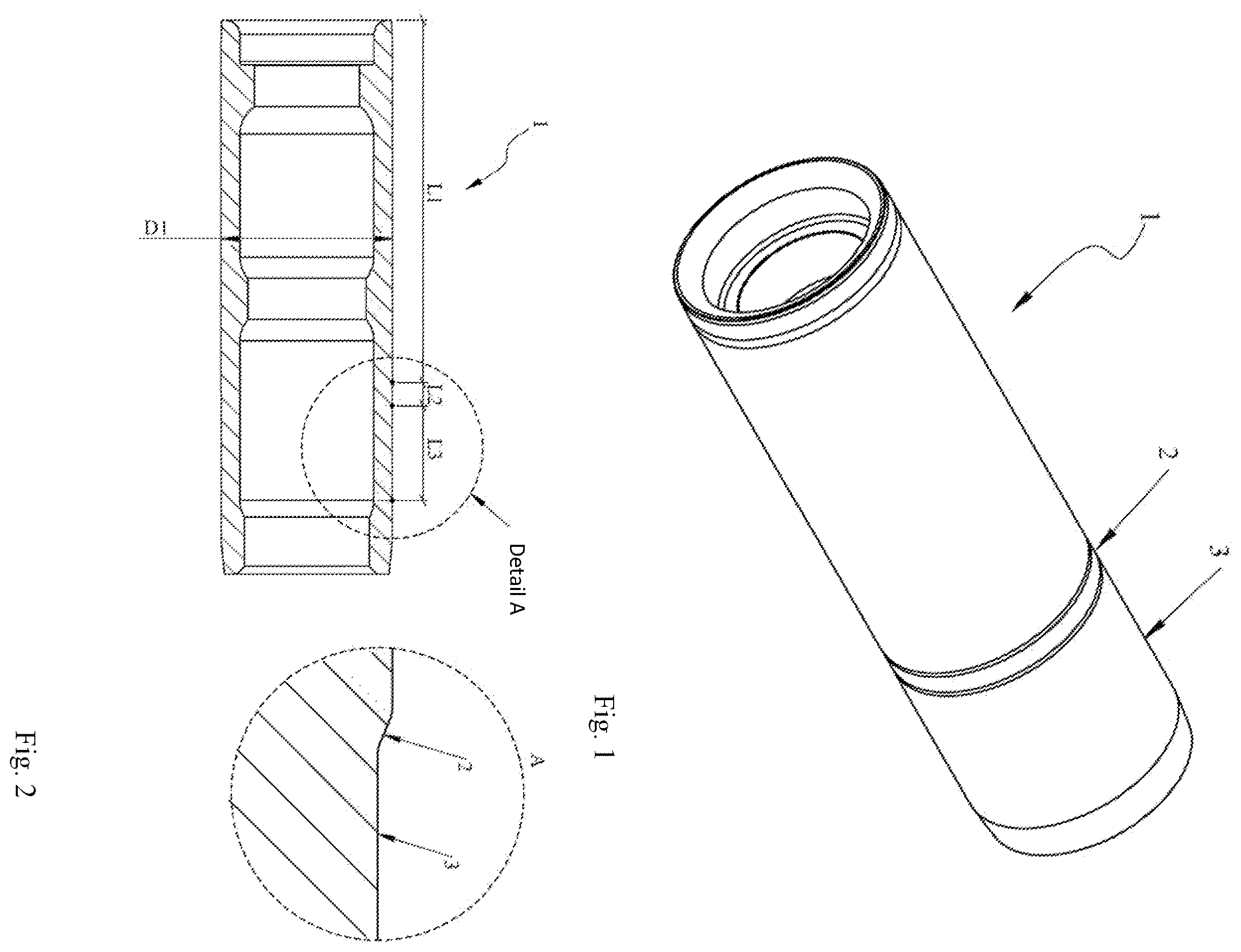
A punch for drawing beverage cans comprising a cylindrical body with a separated region ( 1 ) forming a can side wall having diameter D 1 , a step ( 2 ), and a region ( 3 ) forming a thick wall, characterized in that, the region ( 3 ) forming thick wall starts from the step ( 2 ), and the diameter D 2 of the punch in this region ( 3 ) is variable and is smaller than the diameter D 1 of the region ( 1 ) forming can's sidewall. The object of the invention is also a beverage can in the form of a semi-finished can, and a finished beverage can manufactured with use of the said punch.
Claims (9)
1 . A punch for drawing beverage metal cans comprising a cylindrical body with a separated region ( 1 ) forming a can sidewall having a diameter D 1 , a step ( 2 ), and a region ( 3 ) forming a thick wall in an upper part of the beverage can wherein the region ( 3 ) forming the thick wall starts from the step ( 2 ), and wherein a diameter D 2 of the punch in the region ( 3 ) is variable and is smaller than the diameter D 1 of the region ( 1 ) forming the can's sidewall, wherein: the region ( 3 ) forming a thick wall of the can has length smaller than 100 mm, the diameter D 2 of the punch in the region-forming the thick wall of the can is in the range from 29.7 to 99.9 mm, the diameter D 1 of the punch in the region-forming the can sidewall is in the range from 30 to 100 mm, the step has length (L 2 ) from 0.1 to 40 mm, height from 1 to 500 μm, and an angle in relation to an axis of the punch from 1 to 80 degrees, the step ( 2 ) is disposed between the separated region ( 1 ) and the region ( 3 ), the region ( 3 ) forming a thick wall of the can comprises, in order, a first section ( 5 ) in which the diameter D 2 increases, a second section ( 6 ) in which the diameter D 2 decreases, and a third section ( 7 ) in which the diameter D 2 is parallel to an axis of the punch, and the first section ( 5 ) is closer to the step ( 2 ) than the third section ( 7 ).
Show 8 dependent claims
2 . The punch according to claim 1 , wherein the first section ( 5 ) has length (L 5 ) from 0.01 to 40 mm, and the third section 7 has length (L 7 ) from 0.1 to 30 mm.
3 . The punch according to claim 1 , wherein the region ( 3 ) forming the thick wall of the can comprises a fourth section ( 4 ) having length (L 4 ) from 0.05 to 40 mm, the section ( 5 ) has length (L 5 ) from 0.01 to 40 mm, and the third section 7 has length (L 7 ) from 0.1 to 30 mm.
4 . The punch according to claim 1 , wherein the first section ( 5 ) has length (L 5 ) from 0.01 to 40 mm, the second section ( 6 ) has length (L 6 ) from 0.1 to 30 mm, and the third section ( 7 ) has length (L 7 ) from 0.1 to 30 mm.
5 . The punch according to claim 1 , wherein the region ( 3 ) forming the thick wall of the can comprises a fourth section ( 4 ) having length (L 4 ) from 0.05 to 40 mm, the first section ( 5 ) has length (L 5 ) from 0.01 to 40 mm, the second section ( 6 ) has length (L 6 ) from 0.1 to 30 mm, and the third section ( 7 ) has length ( 7 ) from 0.1 to 30 mm.
6 . The punch according to claim 1 , wherein the diameter D 2 of the punch in the region forming the thick wall of the can is smaller than the diameter D 1 of the punch in the region forming the can body by at least 10 μm.
7 . The punch according to claim 1 wherein the diameter D 2 of the punch in the region forming the thick wall of the can varies linearly or/and non-linearly.
8 . The punch according to claim 1 , wherein the step ( 2 ) tapers inward toward the axis of the punch from D 1 to D 2 .
9 . The punch according to claim 1 , wherein the region ( 3 ) forming a thick wall of the can comprises a fourth section ( 4 ) in which the diameter D 2 is parallel to the axis of the punch, and wherein the fourth section ( 4 ) is disposed between the step ( 2 ) and the first section ( 5 ).
Full Description
Show full text →
CROSS-REFERENCE TO RELATED APPLICATIONS
This application is a 371 National Stage filing of PCT Application No. PCT/IB2022/057702, filed Aug. 17, 2022, which claims priority to PL Patent Application No. P.438791, filed Aug. 20, 2021, which are incorporated by reference herein in their entirety.
TECHNICAL FIELD
The object of the present invention is a new punch for drawing beverage cans, a can in the form of a semi-finished can and a finished can manufactured with use of the said punch.
BACKGROUND ART
Two-piece aluminum cans are manufactured by the DWI, method of drawing and wall ironing, using, inter alia, a horizontal press (bodymaker). In the first stage, the aluminum cup that goes to the horizontal press is drawn to the desired diameter of the can, and then it is ironing through the series of tools, where the thickness of the body/wall is reduced until the designed wall thickness and height of the can are achieved.
The last stage of shaping on a horizontal press is forming the bottom. Then the can is transferred to the trimmer in order to correct the height by cutting the uneven upper edge. After the washing process, the can goes to the printer, oven, spraying the internal varnish and back to the oven. The final shape of the can is created in a multi-stage operation of necking and forming the flange.
Recent years of beverage can development focused on reducing its weight, improving strength parameters and improving the DWI process. Various approaches to this issue are available in the literature, from changing the bottom profile, through changing the roughness of the semi-finished can or raw (input) material to modifying the geometry of the tools.
Patent specification EP2035166B1 provides an expansion die for manufacturing metal containers including a work surface adapted to progressively expanding a diameter of a metal container. The die described in that specification allows for obtaining a unique shape of a can.
Patent specification U.S. Pat. No. 9,566,630B2 discloses a punch for forming aluminum cans, which comprises at least two regions of different surface textures. The new surface of the punch allows for reduction of defects arising during the DWI process.
Unexpectedly, it turned out, that it is possible, by modifying the shape of the punch, to obtain a can with a reduced weight by reducing the thickness of the material in the region of its neck.
DISCLOSURE OF THE INVENTION
A punch for drawing beverage cans comprising a cylindrical body with a separated region forming a can body having diameter D 1 , a step, and a region forming a thick wall according to the present invention is characterized in that, the region forming thick wall starts from the step, and the diameter D 2 of the punch in this region is variable and is smaller than the diameter D 1 of the region forming can's sidewall.
Preferably the region forming a thick wall of the can comprises two forming sections, where the first section has length from 0.01 to 40 mm, and the second section has length from 0.1 to 30 mm.
Preferably the region forming a thick wall of the can comprises three forming sections, where the first section has length from 0.05 to 40 mm, the second section has length from 0.01 to 40 mm, and the third section has length from 0.1 to 30 mm.
Preferably the region forming a thick wall of the can comprises three forming sections, where the first section has length from 0.01 to 40 mm, the second section has length from 0.1 to 30 mm, and the third section has length from 0.1 to 30 mm.
Preferably the region forming a thick wall of the can comprises four forming sections, where the first section the first section has length from 0.05 to 40 mm, the second section has length from 0.01 to 40 mm, the third section has length from 0.1 to 30 mm, and the fourth section has length from 0.1 to 30 mm.
Preferably the region forming a thick wall of the can has length smaller than 100 mm.
Preferably the diameter D 2 of the punch in the region forming the thick wall of the can is in the range 29.7 to 99.9 mm, while the diameter D 1 of the punch in the region forming the can sidewall is in the range from 30 to 100 mm.
Preferably the diameter D 2 of the punch in the region forming the thick wall of the can is smaller than the diameter D 1 of the punch in the region forming the can sidewall by at least 10 μm.
Preferably the step has length from 0.1 to 40 mm, height from 1 to 500 μm, and an angle in relation to the axis of the punch from 1 to 80 degrees.
Preferably the diameter of the punch in the region forming the thick wall of the can varies linearly or/and non-linearly.
A beverage can in the form of a semi-finished can intended for the operation of necking according to the present invention is characterized in that, it has a thick wall of variable thickness t 22 , t 23 ranging from 80 to 220 μm.
Preferably the thickness of the can body t 24 is within the range from 80 to 200 μm.
Preferably the thickness t 22 is smaller than t 23 , the thickness t 22 and t 23 is smaller than t 21 , the thickness t 24 is smaller than t 21 .
A finished beverage can according to the present invention is characterized in that, it has a neck ( 9 ) having wall thickness t 41 , t 42 and t 43 comprising in the range from 80 to 220 μm.
Preferably the wall thickness t 41 =t 42 =t 43 .
Preferably the wall thickness t 43 is bigger than the wall thickness t 41 .
The term “variable diameter” means that the diameter of the punch in the region forming the thick wall is not constant, but changes by increasing or decreasing, which results in the fact that the outer profile of the punch does not extend along the entire length of the area forming the thick wall of the can in a straight line parallel to the punch axis, but can be described by a curved and/or broken line (concave and/or convex function), wherein on some sections, the profile may run in a straight line parallel to the punch axis. A profile selected in this way changes the way the material is formed and affects the final shape and a thick wall thickness of a can after the DWI process. The curvature of individual areas is selected for the design of the can, it differs depending on the thickness of the (input) raw aluminum sheet, diameter, height and shape of the can's neck. The punch can be made of carbon steel, stainless steel, carbides, ceramics and/or a composite material and/or plastic.
The thick wall of the can is a fragment of the semi-finished can in its upper part, which in the process of necking takes the shape of the neck in the final product. The prior art thick wall has a uniform thickness, as for example in WO2020117641A1. Meanwhile, a can in the form of a semi-finished product before the process of necking and forming the neck, manufactured with the use of punch according to the invention, is characterized by a variable thickness of the thick wall. Preferably, the thick wall is thinned in its middle part.
A can made of this semi-finished can is characterized by a lower weight, obtained by reducing the thickness in the upper part of the can, in the neck area. The can, with such a wall in the neck area, is also characterized by lower material consumption, at the same time meets the quality requirements and enables the production of a double seam ensuring proper connection of the can end.
The beverage can according to the invention can be manufactured from aluminum or steel alloys, possibly from other metal alloys.
EXAMPLES
The subject of the invention is disclosed at the drawings, where shows a punch known from the prior art, —its cross-section, shows a punch according to the invention, show a cross-sections of different variants of punches, show a can in the form of a semi-finished can, shows a cross-section of a thick wall known from the prior art, shows a cross-section of a thick wall according to the invention, shows a finished can, shows a cross-section of can's neck known from the prior art, shows a cross-section of can's neck according to the invention.
Example 1
Comparative Example
A punch known from the prior art has a cylindrical body 1 with a step 2 and a region forming a thick wall 3 . The region 3 forming a thick wall in the standard solution is characterized by a constant diameter of the punch in the whole lengths L 3 forming the profile. The profile of the section forming thick wall is defined by a straight line parallel to the axis of the punch. The step may have height from 0.1 to 200 μm, and length from 0.01 to 30 millimeters. The length of the L 3 , defining the thick wall, may vary from 1 to 100 millimeters.
The wall of the semi-finished can for the manufacture of the can after using the known punch in the upper area is thicker than the middle part (thick wall). This is to enable the operation of forming the neck and to ensure the appropriate thickness of the can flange for connection with the lid and making the so-called double seam. The middle part of the can has a wall thickness of 85-100 μm, and the upper in the range 100-250 μm. The thicknesses t 11 , t 12 and t 13 are equal to each other. Minimal differences are the result of the quality and tolerance of the tools. The ratio between the thickness t 11 and t 14 ranges from 0.3 to 0.9. The operation of necking the can causes inhomogeneous thickening of the material in the neck area 9 . Depending on the thickness of the (input) raw aluminum sheet thickness, the wall thickness of the finished can neck t 31 may range from 100 to 300 μm, while t 32 and t 33 from 120-350 μm. The thickness t 35 remains unchanged in relation to the thickness t 14 before the necking operation. The number of necking steps varies depending on the can design i.e. height, diameter, seaming diameter, neck shape and the necking device used. A description of the can neck necking process is given in, for example, U.S. Pat. Nos. 5,724,848A, 4,774,839A and 5,297,414A.
Example 2 (FIG. 4 )
A punch comprises a cylindrical body, where the region forming can sidewall 1 has length 140.5 mm and diameter D 1 equal to 60 mm. The step 2 has length 20 mm and height of 100 μm. The region 3 forming thick wall has length 28 mm, and has variable diameter D 2 . The region 3 forming thick wall consists of four sections. The first section 4 is parallel to the punch axis. The punch diameter D 2 in this section is 59.9 mm. The length L 4 is 2 mm. The second section 5 ma has length L 5 equal to 10 mm. The diameter of the section 5 D 2 increases linearly from 59.9 to 59.95 mm. The section 6 has length of L 6 2 mm, and its diameter D 2 decreases linearly from 59.95 to 59.9. The section 7 has length 14 mm and is parallel to the punch axis. The diameter D 2 of the punch in this region is 59.9 mm.
Example 3 (FIG. 5 )
A punch comprises a cylindrical body, where the region forming can body has length 140 mm and diameter D 1 equal to 60 mm. The step 2 has length 20 mm and height 30 μm. The region 3 forming thick wall has length 30 mm, and has variable punch diameter D 2 . The region 3 forming thick wall consists of three sections. The first section 5 has length L 5 equal to 10 mm. The punch diameter D 2 in the section 5 varies linearly from 59.97 to 59.986 mm. The second section 6 has length L 6 of 2 mm, and the punch diameter D 2 decreases linearly from 59.986 to 59.97. The section 7 has length 20 mm and is parallel to the punch axis. The diameter D 2 of the punch in this region is 59.97 mm.
Example 4 (FIG. 6 )
A punch comprises a cylindrical body, where the region forming can body 1 has length 140 mm and diameter D 1 equal to 60 mm. The step 2 has length 20 mm and height 30 μm. The region 3 forming thick wall has length 30 mm, and has variable punch diameter D 2 . The region 3 forming thick wall consists of two sections. The first section 5 has length L 5 equal to 11 mm. The punch diameter D 2 in the section 5 varies linearly from 59.97 to 59.986 mm. The second section 6 has length L 6 of 2 mm, and the punch diameter D 2 decreases linearly from 59.986 to 59.97. The section 7 has length 20 mm and is parallel to the punch axis. The diameter D 2 of the punch in this region is 59.97 mm.
Example 5 (FIG. 7 )
A punch comprises a cylindrical body, where the region forming can body 1 has length 140 mm and diameter D 1 equal to 60 mm. The step 2 has length 20 mm and height of 30 μm. The region 3 forming thick wall has length 30 mm, and has variable diameter D 2 . The region 3 forming thick wall consists of four sections. The first section 4 is parallel to the punch axis. The punch diameter D 2 in this section is 59.97 mm. The length L 4 is 100 μm. The second section 5 ma has length L 5 equal to 10 mm. The diameter D 2 of the section 5 varies linearly from 59.97 to 59.986 mm. The section 6 has length of L 6 2.5 mm, and its diameter D 2 varies linearly from 59.986 to 59.97. The section 7 has length 25 mm and is parallel to the punch axis. The diameter D 2 of the punch in this region is 59.97 mm.
Example 6
A beverage can in the form of a semi-finished can for manufacturing a finished can of thick wall of variable thickness t 24 equal to 80 μm, t 23 equal to 170 μm, t 22 equal to 30 μm and t 21 equal to 180 μm.
Example 7
A beverage can in the form of a semi-finished can for manufacturing a finished can of thick wall of variable thickness t 24 equal to 78 μm, t 23 equal to 150 μm, t 22 equal to 120 μm and t 21 equal to 170 μm.
Example 8
A beverage can in the form of a semi-finished can for manufacturing a finished can of thick wall of variable thickness t 24 equal to 90 μm, t 23 equal to 180 μm, t 22 equal to 135 μm and t 21 equal to 190 μm.
Example 9
A beverage can in the form of a semi-finished can for manufacturing a finished can of thick wall of variable thickness t 24 equal to 60 μm, t 23 equal to 150 μm, t 22 equal to 110 μm and t 21 equal to 160 μm.
Example 10
A finished beverage can having a neck of a variable wall thickness, where the thickness t 45 is equal to 80 μm, the thickness t 41 is equal to 140 μm, the thickness t 42 equal to 142 μm, the thickness t 43 is equal to 146 μm, and the thickness t 44 is equal to 170 μm.
Example 11
A finished beverage can having a neck of a variable wall thickness, where the thickness t 45 is equal to 60 μm, the thickness t 41 is equal to 120 μm, the thickness t 42 equal to 122 μm, the thickness t 43 is equal to 126 μm, and the thickness t 44 is equal to 160 μm.
Example 12
A finished beverage can having a neck of a variable wall thickness, where the thickness t 45 is equal to 65 μm, the thickness t 41 is equal to 135 μm, the thickness t 42 equal to 135 μm, the thickness t 43 is equal to 140 μm, and the thickness t 44 is equal to 160 μm.
Example 13
A finished beverage can having a neck of a variable wall thickness, where the thickness t 45 is equal to 85 μm, the thickness t 41 is equal to 140 μm, the thickness t 42 equal to 135 μm, the thickness t 43 is equal to 135 μm, and the thickness t 44 is equal to 162 μm.
Example 14
A finished beverage can having a neck of a variable wall thickness, where the thickness t 45 is equal to 65 μm, the thickness t 41 is equal to 135 μm, the thickness t 42 equal to 135 μm, the thickness t 43 is equal to 135 μm, and the thickness t 44 is equal to 160 μm.
Figures (5)
Citations
This patent cites (21)
- US3406554
- US3785311
- US3951296
- US4036047
- US5181409
- US9566630
- US10589334
- US2006/0266092
- US2017/0001231
- US0045115
- US2035166
- US6352721
- US2008132522
- US2009078303
- US2009082989
- US2011006087
- US2013208652
- US2018154407
- US9617700
- US2009100972
- US2011128347