Abstract
An ultrasonic treatment instrument includes: a vibration transmitter including a treatment portion for treating a living tissue at a distal end of the vibration transmitter, the vibration transmitter being configured to transfer ultrasonic vibration from a proximal end of the vibration transmitter toward the treatment portion; a holder configured to open and close with respect to the treatment portion; a resin pad including a gripping surface for gripping the living tissue between the resin pad and the treatment portion; and a heat transmitter that is configured separately from the holder and extends from the holder to an inside of the resin pad.
Claims (11)
1 . An ultrasonic treatment instrument comprising: a rod configured to transmit ultrasonic vibration from a proximal end of the rod toward a distal end of the rod; a holder facing the rod; a resin pad located in the holder, wherein the resin pad is configured to grip a living tissue with the rod; and a sheet made of thermally conductive material disposed between the holder and the resin pad, wherein the sheet is configured to transfer heat from the resin pad to the holder, and wherein the sheet is an adhesive or a heat sealing sheet.
10 . An ultrasonic treatment instrument comprising: a vibration transmitter including a treatment portion for treating a living tissue at a distal end of the vibration transmitter, wherein the vibration transmitter is configured to transfer ultrasonic vibration from a proximal end of the vibration transmitter toward the treatment portion; a holder configured to open and close with respect to the treatment portion; a resin pad including a gripping surface for gripping the living tissue between the resin pad and the treatment portion; and a heat transmitter disposed between the holder and the resin pad, wherein heat transmitter is a graphite sheet.
11 . An ultrasonic treatment instrument comprising: a vibration transmitter including a treatment portion for treating a living tissue at a distal end of the vibration transmitter, wherein the vibration transmitter is configured to transfer ultrasonic vibration from a proximal end of the vibration transmitter toward the treatment portion; a holder configured to open and close with respect to the treatment portion; a resin pad including a gripping surface for gripping the living tissue between the resin pad and the treatment portion; and a heat transmitter disposed between the holder and the resin pad wherein the resin pad is provided with a plurality of holes along a longitudinal direction of the resin pad, and the heat transmitter is configured to enter the plurality of holes.
Show 8 dependent claims
2 . The ultrasonic treatment instrument according to claim 1 , wherein the sheet is a graphite sheet.
3 . The ultrasonic treatment instrument according to claim 1 , wherein the sheet contains any one of boron nitride, alumina, metal powder, carbon nanotube, and silicon carbide.
4 . The ultrasonic treatment instrument according to claim 1 , wherein the resin pad is provided with a plurality of holes along a longitudinal direction of the resin pad, and the sheet is configured to enter the plurality of holes.
5 . The ultrasonic treatment instrument according to claim 1 , wherein the resin pad is provided with a groove portion, and the sheet is provided with a protrusion fitted into the groove portion.
6 . The ultrasonic treatment instrument according to claim 1 , wherein the holder includes a top wall, wherein the resin pad includes a grasping surface facing the rod and a top surface opposed to the grasping surface and facing the top wall, and wherein the sheet is located between the top wall and the top surface.
7 . The ultrasonic treatment instrument according to claim 1 , wherein the holder includes a top wall and a wall surface intersecting with the top wall, wherein the resin pad includes a grasping surface facing the rod and a side surface, wherein the side surface intersects with the grasping surface and faces a side wall, and wherein the sheet is located between the side wall and the side surface.
8 . The ultrasonic treatment instrument according to claim 1 , wherein the sheet is formed from a material having a higher thermal conductivity than the resin pad.
9 . The ultrasonic treatment instrument according to claim 1 , wherein the sheet is configured to dissipate heat of the resin pad.
Full Description
Show full text →
CROSS-REFERENCE TO RELATED APPLICATION
This application is a continuation of International Application No. PCT/JP2021/007919, filed on Mar. 2, 2021, the entire contents of which are incorporated herein by reference.
BACKGROUND
1. Technical Field
The present disclosure relates to an ultrasonic treatment instrument.
2. Related Art
In the related art, there has been known an ultrasonic treatment instrument that treats a treatment target site (hereinafter, referred to as a target site) in a living tissue by applying ultrasonic energy to the target site (see, for example, WO 2018/011918A).
The ultrasonic treatment instrument described in WO 2018/011918A includes a rod, a holder, and a pad (hereinafter, referred to as a resin pad) described below.
The rod includes a treatment portion for treating a living tissue at a distal end, and transfers ultrasonic vibration from a proximal end toward the treatment portion.
The holder opens and closes with respect to the treatment portion.
The resin pad is held with respect to the holder, and has an abutment surface that grips the living tissue between the resin pad and the treatment portion.
SUMMARY
In some embodiments, an ultrasonic treatment instrument includes: a vibration transmitter including a treatment portion for treating a living tissue at a distal end of the vibration transmitter, the vibration transmitter being configured to transfer ultrasonic vibration from a proximal end of the vibration transmitter toward the treatment portion; a holder configured to open and close with respect to the treatment portion; a resin pad including a gripping surface for gripping the living tissue between the resin pad and the treatment portion; and a heat transmitter that is configured separately from the holder and extends from the holder to an inside of the resin pad.
In some embodiments, an ultrasonic treatment instrument includes: a vibration transmitter including a treatment portion for treating a living tissue at a distal end of the vibration transmitter, and the vibration transmitter being configured to transfer ultrasonic vibration from a proximal end of the vibration transmitter toward the treatment portion; a holder configured to open and close with respect to the treatment portion; a resin pad including a gripping surface for gripping the living tissue between the resin pad and the treatment portion; and a heat transmitter disposed between the holder and the resin pad.
The above and other features, advantages and technical and industrial significance of this disclosure will be better understood by reading the following detailed description of presently preferred embodiments of the disclosure, when considered in connection with the accompanying drawings.
BRIEF DESCRIPTION OF THE DRAWINGS
is a view illustrating an ultrasonic treatment instrument according to a first embodiment;
is a view illustrating a distal end portion of the ultrasonic treatment instrument;
is a view illustrating a distal end portion of the ultrasonic treatment instrument;
is a view illustrating a jaw;
is a view illustrating the jaw;
is a view illustrating an arm;
is a view illustrating a wiper jaw;
is a view illustrating the wiper jaw;
is a view illustrating an attachment structure of a resin pad to the wiper jaw;
is a view illustrating an attachment structure of a resin pad to a jaw according to a second embodiment;
is a view illustrating Modification 2-1 of the second embodiment;
is a view illustrating an attachment structure of a resin pad to a jaw according to a third embodiment;
is a view illustrating a heat transmitter;
is a view illustrating an attachment structure of a resin pad to a jaw according to a fourth embodiment;
is a view illustrating the attachment structure of the resin pad to the jaw according to the fourth embodiment;
is a view illustrating the attachment structure of the resin pad to the jaw according to the fourth embodiment;
is a view illustrating Modification 4-1 of the fourth embodiment;
is a view illustrating Modification 4-1 of the fourth embodiment;
is a view illustrating an attachment structure of a resin pad to a jaw according to a fifth embodiment;
is a view illustrating the attachment structure of the resin pad to the jaw according to the fifth embodiment;
is a view illustrating Modification 5-1 of the fifth embodiment;
is a view illustrating Modification 5-1 of the fifth embodiment;
is a view illustrating an attachment structure of a resin pad to a jaw according to a sixth embodiment;
is a view illustrating Modification 6-1 of the sixth embodiment;
is a view illustrating Modification 6-2 of the sixth embodiment;
is a view illustrating Modification 6-3 of the sixth embodiment;
is a view illustrating Modification 6-4 of the sixth embodiment;
is a view illustrating Modification 6-5 of the sixth embodiment;
is a view illustrating Modification 6-6 of the sixth embodiment;
is a view illustrating Modification 6-7 of the sixth embodiment;
is a view illustrating Modification 6-8 of the sixth embodiment;
is a view illustrating Modification 6-9 of the sixth embodiment;
is a view illustrating Modification 7-1 of the first to sixth embodiments;
is a view illustrating Modification 7-2 of the first to sixth embodiments;
is a view illustrating Modification 7-3 of the first to sixth embodiments;
is a view illustrating Modification 7-4 of the first to sixth embodiments;
is a view illustrating Modification 7-5 of the first to sixth embodiments;
is a view illustrating Modification 7-6 of the first to sixth embodiments;
is a view illustrating Modification 7-6 of the first to sixth embodiments;
is a view illustrating Modification 7-7 of the first to sixth embodiments;
is a view illustrating Modification 7-8 of the first to sixth embodiments;
is a view illustrating Modification 7-9 of the first to sixth embodiments;
is a view illustrating Modification 7-11 of the first to sixth embodiments;
is a view illustrating Modification 7-14 of the first to sixth embodiments;
is a view illustrating Modification 7-14 of the first to sixth embodiments;
is a view illustrating Modification 7-14 of the first to sixth embodiments; and
is a view illustrating Modification 7-14 of the first to sixth embodiments.
DETAILED DESCRIPTION
Hereinafter, modes for carrying out the disclosure (hereinafter, embodiments) will be described with reference to the drawings. The disclosure is not limited by the embodiments described below. Furthermore, in the description of the drawings, the same portions are denoted by the same reference numerals.
First Embodiment
Schematic Configuration of Ultrasonic Treatment Instrument
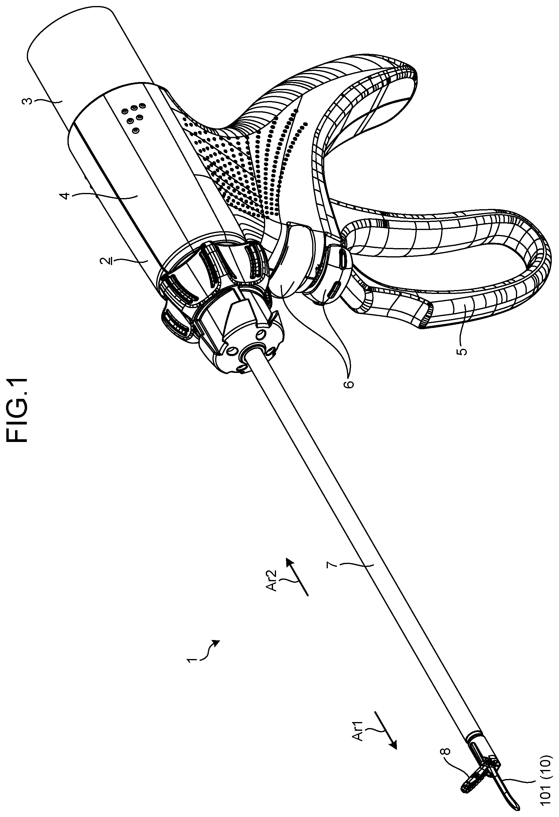
is a view illustrating an ultrasonic treatment instrument 1 according to a first embodiment. are views illustrating a distal end portion of the ultrasonic treatment instrument 1 . Specifically, is a view of the distal end portion of the ultrasonic treatment instrument 1 viewed along a normal direction of a plane including a central axis Ax of a sheath 7 in a state where a jaw 8 and a vibration transmitter 10 are included in the plane. is a cross-sectional view of the distal end portion of the ultrasonic treatment instrument 1 cut along the plane including the central axis Ax of the sheath 7 in a state where the jaw 8 and the vibration transmitter 10 are included in the plane. A “width direction” described below means a direction orthogonal to paper surfaces of .
The ultrasonic treatment instrument 1 applies ultrasonic energy and high-frequency energy to a treatment target site (hereinafter, referred to as a target site) in a living tissue to treat the target site. Here, the treatment means, for example, coagulation and incision of the target site. As illustrated in , the ultrasonic treatment instrument 1 includes a handpiece 2 and an ultrasonic transducer 3 .
As illustrated in to 3 , the handpiece 2 includes a holding case 4 ( ), an operation handle 5 ( ), a switch 6 ( ), a sheath 7 , a jaw 8 , a resin pad 9 ( ), and a vibration transmitter 10 .
The holding case 4 supports the entire ultrasonic treatment instrument 1 .
The operation handle 5 is movably attached to the holding case 4 and receives an opening/closing operation by an operator.
The switch 6 is provided in a state of being exposed to an outside of the holding case 4 , and receives an output start operation by the operator. Then, the switch 6 outputs an operation signal corresponding to the output start operation to a control device (not illustrated) electrically coupled to the ultrasonic treatment instrument 1 .
The sheath 7 has a substantially cylindrical shape as a whole. Hereinafter, one side along the central axis Ax of the sheath 7 is referred to as a distal end side Art ( to 3 ), and the other side is referred to as a proximal end side Ar 2 ( to 3 ). Then, the sheath 7 is attached to the holding case 4 by inserting a portion of the proximal end side Ar 2 into the holding case 4 from the distal end side Ar 1 of the holding case 4 .
In the sheath 7 , an outer peripheral surface is covered with an electrically insulating outer tube TO (see ).
In addition, in the sheath 7 , an inner peripheral surface is covered with an electrically insulating inner tube TI (see ).
In the following description of the configuration of the jaw 8 and the resin pad 9 , a side away from a treatment portion 101 configuring the vibration transmitter will be referred to as a back surface side Ar 3 (see to 9 ), and a side close to the treatment portion 101 will be referred to as a treatment portion side Ar 4 (see to 9 ).
are views illustrating the jaw 8 . Specifically, is a perspective view of the jaw 8 as viewed from the back surface side Ar 3 . is a perspective view of the jaw 8 as viewed from the treatment portion side Ar 4 . illustrates a state in which the resin pad 9 is assembled to the jaw 8 .
The jaw 8 corresponds to a holder. The jaw 8 can be opened and closed with respect to the treatment portion 101 ( ) by being pivotally supported with respect to an end portion of the sheath 7 on the distal end side Art. Then, when the jaw 8 is closed with respect to the treatment portion 101 , the target site is gripped between the resin pad 9 held by the jaw 8 and the treatment portion 101 . As illustrated in or 5 , the jaw 8 includes an arm 81 and a wiper jaw 82 .
is a view illustrating the arm 81 . Specifically, is a perspective view of the arm 81 as viewed from the treatment portion side Ar 4 .
The arm 81 is made of an electrically conductive material. As illustrated in , the arm 81 is a member in which an arm body 811 and a pair of bearing portions 812 are integrally formed.
The arm body 811 is formed of a substantially long plate body. In the present first embodiment, a longitudinal direction of the arm body 811 is a direction along a curve toward a left side as it goes toward the distal end side Ar 1 when viewed from the proximal end side Ar 2 in a state where the jaw 8 is positioned on an upper side with respect to the treatment portion 101 .
In the arm body 811 , as illustrated in , a first recess 811 a extending from the proximal end toward the distal end side Ar 1 along the longitudinal direction of the arm body 811 is provided on a surface on the treatment portion side Ar 4 .
As illustrated in , first insertion holes 811 c that penetrate in the width direction and through which first pins Pit ( ) are inserted are provided respectively in side wall portions 811 b on both sides of the arm body 811 constituting the first recess 811 a in the width direction. The two first insertion holes 811 c are positioned substantially at the center of the arm body 811 in the longitudinal direction respectively. In addition, a straight line connecting the two first insertion holes 811 c is parallel to the width direction. In the present first embodiment, the first pin Pit is fixed to the arm body 811 by welding in a state of being inserted into each of the first insertion holes 811 c.
In addition, an electrically insulating resin cover RC ( to 6 ) is integrally formed on the surface of the arm body 811 on the back surface side Ar 3 in a state of covering the surface of the back surface side Ar 3 . In the present first embodiment, the resin cover RC is insert-molded with respect to the arm body 811 , but the disclosure is not limited thereto. For example, a configuration in which the resin cover RC is fixed to the arm body 811 by snap-fitting or a metal pin may be adopted.
Each of the pair of bearing portions 812 is provided at the proximal end of the arm body 811 , and is formed of plate bodies facing each other in the width direction.
As illustrated in , each of the pair of bearing portions 812 is provided with a second insertion hole 812 a that penetrates the front and back surfaces respectively and through which each of two second pins Pi 2 is inserted. That is, the arm 81 is coupled to the sheath 7 by the two second pins Pi 2 .
In addition, as illustrated in , each of the pair of bearing portions 812 is provided with a third insertion hole 812 b which penetrates the front and back surfaces respectively and through which a third pin Pi 3 is inserted. In the present first embodiment, the third pin Pi 3 is fixed to the arm 81 by welding in a state of being inserted into each of fourth insertion holes 711 ( ) and each of the third insertion holes 812 b of an opening/closing mechanism 71 constituting the sheath 7 . That is, the arm 81 is coupled to the opening/closing mechanism 71 by the third pin Pi 3 . Then, the arm 81 rotates about the two second pins Pi 2 in conjunction with the movement of the opening/closing mechanism 71 to the distal end side Ar 1 or the proximal end side Ar 2 according to the opening and closing operation to the operation handle 5 by the operator. As a result, the jaw 8 is opened and closed with respect to the treatment portion 101 .
are views illustrating the wiper jaw 82 . Specifically, is a perspective view of the wiper jaw 82 as viewed from the back surface side Ar 3 . is a view of the wiper jaw 82 as viewed along the width direction. illustrate a state in which the resin pad 9 is assembled to the wiper jaw 82 .
The wiper jaw 82 is made of an electrically conductive material such as stainless steel or a titanium alloy, and is attached to the arm 81 . As illustrated in or 8 , the wiper jaw 82 includes a wiper jaw body 83 , a plurality of first tooth portions 84 ( ), and a plurality of second tooth portions 85 .
The wiper jaw body 83 is formed of an elongated plate body extending along the longitudinal direction of the arm body 811 . In addition, an outer shape of the wiper jaw body 83 is set to be substantially the same as an inner surface shape of the first recess 811 a . Then, the wiper jaw body 83 is disposed in the first recess 811 a.
In the wiper jaw body 83 , a second recess 831 (see ) that penetrates from the proximal end to the distal end along the longitudinal direction of the wiper jaw body 83 and in which the resin pad 9 is disposed is provided on the surface on the treatment portion side Ar 4 . Hereinafter, a bottom surface of the second recess 831 is referred to as a bottom surface 831 a , and side wall portions on both sides of the second recess 831 in the width direction are referred to as side wall portions 831 b.
In addition, as illustrated in or 8 , the wiper jaw body 83 is provided with a fifth insertion hole 831 c which penetrates from one side wall portion 831 b to the other side wall portion 831 b along the width direction and through which the first pin Pit is inserted. The fifth insertion hole 831 c is positioned substantially at the center of the wiper jaw body 83 in the longitudinal direction. In addition, a central axis of the fifth insertion hole 831 c is parallel to the width direction. Then, the wiper jaw body 83 is pivotally supported with respect to the arm 81 so as to be swingable about the first pin Pit. That is, by making the wiper jaw 82 swingable about the first pin Pit, a position where a strongest force is applied to the target site when the target site is gripped between the jaw 8 and the treatment portion 101 is positioned at substantially the center of the jaw 8 in the longitudinal direction instead of the proximal end side Ar 2 of the jaw 8 . As a result, a force is substantially uniformly applied to the target site gripped between the jaw 8 and the treatment portion 101 .
The plurality of first tooth portions 84 protrude from the one side wall portion 831 b toward the treatment portion side Ar 4 respectively, and are arranged side by side along the longitudinal direction of the wiper jaw body 83 .
The plurality of second tooth portions 85 protrude from the other side wall portion 831 b toward the treatment portion side Ar 4 respectively, and are arranged side by side along the longitudinal direction of the wiper jaw body 83 .
Then, the plurality of first tooth portions 84 and the plurality of second tooth portions 85 are provided in a state where the resin pad 9 is sandwiched in a state where the resin pad 9 is attached to the wiper jaw 82 (see ).
The resin pad 9 is softer than the vibration transmitter 10 , is made of a resin material having electrical insulation and biocompatibility, for example, polytetrafluoroethylene (PTFE), and has a substantially rectangular parallelepiped shape extending along the longitudinal direction of the arm body 811 . In addition, in the resin pad 9 , a third recess 91 (see ) extending from the proximal end toward the distal end side Ar 1 is provided on the surface on the treatment portion side Ar 4 . Further, the resin pad 9 is disposed inside the second recess 831 . Then, when the jaw 8 is brought close to the treatment portion 101 , a bottom surface 911 (see ) of the third recess 91 of the resin pad 9 abuts on the treatment portion 101 . The bottom surface 911 has a substantially flat shape. Then, the bottom surface 911 corresponds to a gripping surface. Hereinafter, for convenience of description, the bottom surface 911 is referred to as a gripping surface 911 .
The attachment structure of the resin pad 9 to the jaw 8 will be described later in “Attachment Structure of Resin Pad to Jaw”.
The vibration transmitter 10 has an elongated shape and is made of an electrically conductive material. Then, as illustrated in or 3 , the vibration transmitter 10 is inserted into the sheath 7 in a state where the treatment portion 101 is exposed to the outside. The vibration transmitter 10 includes the treatment portion 101 and a shaft 102 .
The treatment portion 101 is provided at the distal end of the shaft 102 . Similarly to the jaw 8 , the treatment portion 101 extends along a curve toward the left side as it goes toward the distal end side Ar 1 as viewed from the proximal end side Ar 2 in a state where the jaw 8 is positioned on the upper side.
The shaft 102 has an elongated shape extending along the central axis Ax, and an end portion on the proximal end side Ar 2 is coupled to a bolted Langevin type transducer (BLT) constituting the ultrasonic transducer 3 . Then, the shaft 102 transfers the ultrasonic vibration generated by the BLT from the end portion on the proximal end side Ar 2 to the treatment portion 101 . In the present first embodiment, the ultrasonic vibration is longitudinal vibration that vibrates in a direction along the central axis Ax. At this time, the treatment portion 101 vibrates with a desired amplitude by the longitudinal vibration of the vibration transmitter 10 .
An annular lining LI (see ) having electrical insulation and elasticity and extending along a circumferential direction around a central axis of the shaft 102 is attached to the outer peripheral surface of the shaft 102 described above. The lining LI is disposed at each position of a node of the longitudinal vibration of the vibration transmitter 10 . Then, the lining LI abuts on the inner tube TI in a state where the vibration transmitter 10 is inserted into the sheath 7 . The inner tube TI has a function of securing electrical insulation between the sheath 7 and the vibration transmitter 10 . In addition, the lining LI has a function of sealing liquid that has entered a gap between the inner tube TI and the vibration transmitter 10 .
The ultrasonic transducer 3 is detachably coupled to an end portion of the holding case 4 on the proximal end side Ar 2 . Although not specifically illustrated, the ultrasonic transducer 3 includes a BLT that generates ultrasonic vibration in response to supply of AC power.
The control device (not illustrated) electrically coupled to the ultrasonic treatment instrument 1 described above controls the operation of the ultrasonic treatment instrument 1 as described below according to the operation signal from the switch 6 .
The control device supplies high-frequency power between the jaw 8 and the treatment portion 101 via the sheath 7 and the shaft 102 . Then, a high-frequency current flows between the treatment portion 101 and the plurality of first and second tooth portions 84 and 85 having the same potential. That is, the high-frequency current flows through the target site gripped between the jaw 8 and the treatment portion 101 . In other words, high-frequency energy is applied to the target site.
In addition, the control device supplies AC power to the BLT constituting the ultrasonic transducer 3 to generate ultrasonic vibration in the BLT. Then, ultrasonic vibration is applied from the treatment portion 101 to the target site gripped between the jaw 8 and the treatment portion 101 . In other words, ultrasonic energy is applied to the target site.
Then, Joule heat is generated in the target site by the flow of the high-frequency current. In addition, frictional heat is generated between the treatment portion 101 and the target site by the vertical vibration of the treatment portion 101 . As a result, the target site is incised while coagulating.
Attachment Structure of Resin Pad to Jaw
Next, an attachment structure of the resin pad 9 to the jaw 8 will be described.
is a view illustrating the attachment structure of the resin pad 9 to the jaw 8 . Specifically, is a cross-sectional view of the wiper jaw 82 on which the resin pad 9 is taken, taken along a plane orthogonal to the longitudinal direction of the wiper jaw 82 .
As illustrated in , the resin pad 9 is attached to the wiper jaw 82 by a heat transmitter 11 inside the second recess 831 .
The heat transmitter 11 is configured separately from the jaw 8 , and is a member that transfers the heat of the resin pad 9 from the resin pad 9 to the jaw 8 (wiper jaw 82 ). In the present first embodiment, the heat transmitter 11 is made of a material having higher thermal conductivity than the resin pad 9 and the wiper jaw 82 . As a material of the heat transmitter 11 , for example, aluminum, gold, silver, copper, or the like can be exemplified. In addition, the heat transmitter 11 may be made of the same material as the wiper jaw 82 . In addition, as illustrated in , the heat transmitter 11 has a pin shape.
Then, in a state where the heat transmitter 11 penetrates the resin pad 9 in the width direction, end portions on one end side and the other end side are respectively coupled to the side wall portions 831 b on both sides of the wiper jaw body 83 in the width direction. That is, the heat transmitter 11 is bridged between the wiper jaw body 83 and the resin pad 9 . In this state, the substantially central portion of the heat transmitter 11 is positioned in a projection area ArP obtained by projecting the gripping surface 911 toward the back surface side Ar 3 along the opening/closing direction of the jaw 8 . Then, the heat of the gripping surface 911 moves along a heat transfer path of the resin pad 9 to the heat transmitter 11 to the wiper jaw body 83 to the first pin Pit and to the arm 81 as indicated by arrows in .
Although not specifically illustrated, a plurality of the heat transmitters 11 are arranged side by side at predetermined intervals along the longitudinal direction of the resin pad 9 . That is, the resin pad 9 is attached to the wiper jaw body 83 by the plurality of heat transmitters 11 inside the second recess 831 .
According to the present first embodiment described above, the following effects are obtained.
The ultrasonic treatment instrument 1 according to the present first embodiment includes the heat transmitter 11 that is configured separately from the jaw 8 and transfers the heat of the resin pad 9 from the resin pad 9 to the jaw 8 (wiper jaw 82 ).
Therefore, frictional heat generated in the resin pad 9 (gripping surface 911 ) by application of ultrasonic vibration can be moved along the heat transfer path of the resin pad 9 to a heat transmitter 11 and to the jaw 8 .
Therefore, according to the ultrasonic treatment instrument 1 according to the present first embodiment, deterioration of the resin pad 9 can be suppressed.
In particular, the heat transmitter 11 is made of a material having higher thermal conductivity than the resin pad 9 . Therefore, a dissipation efficiency of heat from the resin pad 9 along the heat transfer path described above can be improved, and the deterioration of the resin pad 9 can be further suppressed.
In addition, a portion of the heat transmitter 11 is positioned in the projection area ArP where frictional heat generated on the gripping surface 911 is easily transferred in the resin pad 9 . Therefore, the heat of the resin pad 9 can be effectively received by the heat transmitter 11 , and the heat can be dissipated along the heat transfer path described above, and the deterioration of the resin pad 9 can be further suppressed.
Second Embodiment
Next, the present second embodiment will be described.
In the following description, the same reference numerals are given to the same configurations as those of the above-described first embodiment, and a detailed description thereof will be omitted or simplified.
The present second embodiment is different from the above-described first embodiment in the attachment structure of the resin pad 9 to the jaw 8 . Hereinafter, for convenience of description, the jaw 8 and the wiper jaw 82 according to the present second embodiment are referred to as a jaw 8 A and a wiper jaw 82 A, respectively. In addition, the resin pad 9 according to the present second embodiment is referred to as a resin pad 9 A.
is a view illustrating an attachment structure of the resin pad 9 A to the jaw 8 A according to the second embodiment. Specifically, is a cross-sectional view of the resin pad 9 A and the jaw 8 A taken along a plane orthogonal to the longitudinal direction of the jaw 8 A. In , for convenience of explanation, the arm 81 and the resin cover RC in the jaw 8 A are illustrated as one member.
The jaw 8 A is different from the jaw 8 described in the above-described first embodiment in that a wiper jaw 82 A having a different shape from the wiper jaw 82 is adopted.
As illustrated in , the wiper jaw 82 A is different from the wiper jaw 82 described in the above-described first embodiment in that a pair of claws 831 d are provided.
As illustrated in , the pair of claws 831 d linearly protrude in directions approaching each other from positions facing each other along the width direction in each side wall portion 831 b , and extend along the longitudinal direction of the wiper jaw 82 A.
In addition, as illustrated in , the resin pad 9 A is different from the resin pad 9 described in the above-described first embodiment in that a pair of slits 92 are provided.
As illustrated in , in the resin pad 9 A, the pair of slits 92 are provided on each side surface intersecting the surface on the treatment portion side Ar 4 in a state of penetrating from the distal end toward the proximal end along the longitudinal direction of the resin pad 9 A. Then, the resin pad 9 A is attached to the wiper jaw 82 A by being slid along the longitudinal direction of the wiper jaw 82 A in a state where the pair of claws 831 d enter the pair of slits 92 inside the second recess 831 . That is, in the present second embodiment, the heat transmitter 11 described in the above-described first embodiment is omitted.
The installation method of the resin pad 9 A is not limited to the sliding method described above. For example, by using the elasticity of the resin pad 9 A, an installation method in which the resin pad 9 A is screwed until the pair of claws 831 d enter the pair of slits 92 from the lower side to the upper side in may be adopted.
In the present second embodiment, as illustrated in , a heat transmitter 11 A is disposed between an outer surface of the resin pad 9 A and the bottom surface 831 a , the side wall portions 831 b , and the first and second tooth portions 84 and 85 in a state of avoiding the pair of claws 831 d . In this state, in the heat transmitter 11 A, a central portion in the width direction of a portion disposed between the outer surface of the resin pad 9 A and the bottom surface 831 a is positioned in the projection area ArP as illustrated in .
Similarly to the heat transmitter 11 described in the above-described first embodiment, the heat transmitter 11 A is a member that is configured separately from the jaw 8 A and transfers the heat of the resin pad 9 A from the resin pad 9 A to the jaw 8 A (wiper jaw 82 A). In the present second embodiment, the heat transmitter 11 A has a sheet shape and is made of a material having higher thermal conductivity than the resin pad 9 A. For example, the heat transmitter 11 A is a graphite sheet. Then, the heat of the gripping surface 911 moves along a heat transfer path of the resin pad 9 A to the heat transmitter 11 A to the wiper jaw 82 A to the first pin Pit and to the arm 81 .
The heat transmitter 11 A may have the same length dimension as the entire length of the resin pad 9 A in the longitudinal direction, or may have a length dimension shorter than the entire length.
Even in the case of adopting the structure in the above-described present second embodiment, the same effects as those of the above-described first embodiment are obtained.
In the above-described first embodiment, the heat transmitter 11 A may be disposed between the outer surface of the resin pad 9 and the bottom surface 831 a , the side wall portions 831 b , and the first and second tooth portions 84 and 85 .
Modification 2-1 of Second Embodiment
is a view illustrating Modification 2-1 of the second embodiment. Specifically, is a cross-sectional view corresponding to .
In the above-described second embodiment, as in the present Modification 2-1 illustrated in , the heat transmitter 11 A may be disposed only between the outer surface of the resin pad 9 A and the bottom surface 831 a and the side wall portions 831 b in a state of avoiding the pair of claws 831 d.
Third Embodiment
Next, the present third embodiment will be described.
In the following description, the same reference numerals are given to the same configurations as those of the above-described first embodiment, and a detailed description thereof will be omitted or simplified.
The present third embodiment is different from the above-described first embodiment in the attachment structure of the resin pad 9 to the jaw 8 . Hereinafter, for convenience of description, the jaw 8 and the wiper jaw 82 according to the present second embodiment are referred to as a jaw 8 B and a wiper jaw 82 B, respectively. In addition, the resin pad 9 according to the present second embodiment will be referred to as a resin pad 9 B.
is a view illustrating an attachment structure of the resin pad 9 B to the jaw 8 B. Specifically, is a cross-sectional view corresponding to .
The jaw 8 B is different from the jaw 8 described in the above-described first embodiment in that the wiper jaw 82 B having a different shape from the wiper jaw 82 is adopted.
As illustrated in , the wiper jaw 82 B is different from the wiper jaw 82 described in the above-described first embodiment in that a sixth insertion hole 831 e is provided.
The sixth insertion hole 831 e is positioned substantially at the center of the wiper jaw body 83 in the longitudinal direction, and penetrates from the upper outer surface to the inside of the second recess 831 through the fifth insertion hole 831 c in .
In addition, as illustrated in , the resin pad 9 B is different from the resin pad 9 described in the above-described first embodiment in that a groove portion 93 is provided.
The groove portion 93 corresponds to an engagement receiving portion. The groove portion 93 linearly extends from the surface facing the bottom surface 831 a toward the gripping surface 911 in the resin pad 9 B, and has a T-shaped cross section in which the extended distal end portions linearly extend in the width direction, respectively. Then, the groove portion 93 penetrates from the distal end to the proximal end of the resin pad 9 B along the longitudinal direction of the resin pad 9 B.
Then, as illustrated in , the resin pad 9 B is attached to the wiper jaw 82 B by a heat transmitter 11 B different from the heat transmitter 11 described in the first embodiment inside the second recess 831 .
is a view illustrating the heat transmitter 11 B. Specifically, is a view of the heat transmitter 11 B to which the resin pad 9 B is attached as viewed along the width direction.
Similarly to the heat transmitter 11 described in the above-described first embodiment, the heat transmitter 11 B is a member that is configured separately from the jaw 8 B and transfers the heat of the resin pad 9 B from the resin pad 9 B to the jaw 8 B (wiper jaw 82 B). In the present third embodiment, the heat transmitter 11 B is made of a material having higher thermal conductivity than the resin pad 9 B and the wiper jaw 82 B. As a material of the heat transmitter 11 B, for example, aluminum, gold, silver, copper, or the like can be exemplified. In addition, the heat transmitter 11 B may be made of the same material as the wiper jaw 82 B. Then, as illustrated in or 13 , the heat transmitter 11 B includes a pad side coupling portion 111 and a jaw side coupling portion 112 .
The pad side coupling portion 111 is a portion coupled to the resin pad 9 B and corresponds to an engaging portion. The pad side coupling portion 111 is formed in an elongated shape having a length dimension substantially the same as the entire length of the resin pad 9 B in the longitudinal direction, and has a T-shaped cross section substantially the same as the groove portion 93 . Then, as illustrated in , the pad side coupling portion 111 is inserted (engaged) into groove portion 93 . As a result, the heat transmitter 11 B holds the resin pad 9 B. In this state, most of the heat transmitter 11 B is positioned in the projection area ArP.
The jaw side coupling portion 112 is a portion coupled to the jaw 8 B and corresponds to a coupling portion. The jaw side coupling portion 112 protrudes upward in from a substantially central portion of the pad side coupling portion 111 in the longitudinal direction at an upper end portion of the pad side coupling portion 111 in . In addition, as illustrated in or 13 , the jaw side coupling portion 112 is provided with a seventh insertion hole 112 a penetrating along the width direction.
In the heat transmitter 11 B described above, the first pin Pit is inserted into the seventh insertion hole 112 a together with the fifth insertion hole 831 c in a state where the jaw side coupling portion 112 is inserted into the sixth insertion hole 831 e . As a result, the heat transmitter 11 B and the resin pad 9 B are pivotally supported with respect to the arm 81 so as to be swingable about the first pin Pit together with the wiper jaw 82 B.
Then, the heat of the gripping surface 911 moves along a heat transfer path of the resin pad 9 B to the heat transmitter 11 B to the wiper jaw 82 B and to the arm 81 .
The coupling between the heat transmitter 11 B and the jaw 8 B is not limited to the above-described structure, and other mechanical coupling structures may be adopted, or a thermally conductive adhesive may be used.
Even in the case of adopting the structure in the above-described present third embodiment, the same effects as those of the above-described first embodiment are obtained.
Fourth Embodiment
Next, the present fourth embodiment will be described. In the following description, the same reference numerals are given to the same configurations as those of the above-described first embodiment, and a detailed description thereof will be omitted or simplified.
The present fourth embodiment is different from the above-described first embodiment in the attachment structure of the resin pad 9 to the jaw 8 . Hereinafter, for convenience of description, the jaw 8 and the wiper jaw 82 according to the present fourth embodiment are referred to as a jaw 8 C and a wiper jaw 82 C, respectively. In addition, the resin pad 9 according to the present fourth embodiment is referred to as a resin pad 9 C.
to 16 are views illustrating an attachment structure of the resin pad 9 C to the jaw 8 C according to the fourth embodiment. Specifically, to 16 are cross-sectional views corresponding to , and sequentially illustrate an installation method of a heat transmitter 11 C and the resin pad 9 C with respect to the wiper jaw 82 C. In to 16 , illustration of the first and second tooth portions 84 and 85 is omitted for convenience of description.
The jaw 8 C is different from the jaw 8 described in the above-described first embodiment in that the wiper jaw 82 C having a different shape from the wiper jaw 82 is adopted.
As illustrated in to 16 , the wiper jaw 82 C is similar to the wiper jaw 82 A described in the above-described second embodiment.
In addition, as illustrated in to 16 , the resin pad 9 C is similar to the resin pad 9 A described in the above-described second embodiment. That is, similarly to the resin pad 9 A described in the above-described second embodiment, the resin pad 9 C is attached to the wiper jaw 82 C in a state where the pair of claws 831 d enter the pair of slits 92 inside the second recess 831 . Therefore, in the present fourth embodiment, the heat transmitter 11 described in the above-described first embodiment is omitted.
The installation method of the resin pad 9 C is not limited to the sliding method described above. For example, by using the elasticity of the resin pad 9 C, an installation method in which the resin pad 9 C is screwed until the pair of claws 831 d enter the pair of slits 92 in the direction indicated by an arrow in may be adopted.
In the present fourth embodiment, as illustrated in to 16 , the heat transmitter 11 C is disposed between an outer surface of the resin pad 9 C and an inner surface of the second recess 831 inside the second recess 831 .
Similarly to the heat transmitter 11 described in the above-described first embodiment, the heat transmitter 11 C is a member that is configured separately from the jaw 8 C and transfers the heat of the resin pad 9 C from the resin pad 9 C to the jaw 8 C (wiper jaw 82 C). In the present third embodiment, the heat transmitter 11 C is an adhesive including a thermal conductive substance or a heat sealing sheet. As the thermal conductive substance, boron nitride, alumina, metal powder, carbon nanotube, silicon carbide, and the like can be exemplified.
Then, for example, as described below, the heat transmitter 11 C is provided between the outer surface of the resin pad 9 C and the inner surface of the second recess 831 inside the second recess 831 .
First, as illustrated in , the worker applies or disposes the heat transmitter 11 C on the bottom surface 831 a . Next, as illustrated in , the worker sets a state in which the pair of claws 831 d enter the pair of slits 92 . Then, the worker presses the resin pad 9 C toward the bottom surface 831 a as indicated by an arrow in . As a result, as illustrated in , a portion of the heat transmitter 11 C enters between the claw 831 d and the slit 92 from between the resin pad 9 C and the bottom surface 831 a . In this state, in the heat transmitter 11 C, the central portion of the portion disposed between the outer surface of the resin pad 9 C and the bottom surface 831 a in the width direction is positioned in the projection area ArP.
Then, the heat of the gripping surface 911 moves along a heat transfer path of the resin pad 9 C to the heat transmitter 11 C to the wiper jaw 82 C to the first pin Pit and to the arm 81 .
The heat transmitter 11 C may have the same length dimension as the entire length of the resin pad 9 C in the longitudinal direction, or may have a length dimension shorter than the entire length.
Even in the case of adopting the structure in the present fourth embodiment described above, the same effects as those of the above-described first embodiment are obtained.
In addition, the heat transmitter 11 C is an adhesive including a thermal conductive substance or a heat sealing sheet. Therefore, a cross-sectional area of the heat transfer path of the resin pad 9 C to the wiper jaw 82 C can be enlarged, and a thermal resistance in the heat transfer path can be reduced.
Modification 4-1 of Fourth Embodiment
are views illustrating Modification 4-1 of the fourth embodiment. Specifically, are cross-sectional views of the wiper jaw 82 C, the resin pad 9 C, and the heat transmitter 11 C according to the present Modification 4-1 as viewed along the width direction, and sequentially illustrate the installation method of the resin pad 9 C and the heat transmitter 11 C with respect to the wiper jaw 82 C.
In the above-described fourth embodiment, a plurality of coupling holes 94 may be provided on the surface of the resin pad 9 C facing the bottom surface 831 a as in the present Modification 4-1 illustrated in .
As illustrated in or 18 , the coupling hole 94 extends linearly from the surface of the resin pad 9 C facing the bottom surface 831 a toward the gripping surface 911 , and has a cross-sectional T shape in which the extended distal end portions extend linearly in the longitudinal direction of the resin pad 9 C respectively. Then, the plurality of coupling holes 94 are arranged side by side along the longitudinal direction of the resin pad 9 C.
Then, as described in the above-described fourth embodiment, after the heat transmitter 11 C is applied or disposed on the bottom surface 831 a and the pair of claws 831 d enter the pair of slits 92 , the resin pad 9 C is pressed toward the bottom surface 831 a . As a result, as illustrated in , a portion of the heat transmitter 11 C enters the plurality of coupling holes 94 from between the resin pad 9 C and the bottom surface 831 a.
Therefore, a bonding strength of the resin pad 9 C to the wiper jaw 82 C is improved, the cross-sectional area of the heat transfer path of the resin pad 9 C to the wiper jaw 82 C is enlarged, and the thermal resistance in the heat transfer path can be reduced.
Fifth Embodiment
Next, the present fifth embodiment will be described.
In the following description, the same reference numerals are given to the same configurations as those of the above-described first embodiment, and a detailed description thereof will be omitted or simplified.
The present fifth embodiment is different from the above-described first embodiment in the attachment structure of the resin pad 9 to the jaw 8 . Hereinafter, for convenience of description, the jaw 8 and the wiper jaw 82 according to the present fifth embodiment are referred to as a jaw 8 D and a wiper jaw 82 D, respectively. In addition, the resin pad 9 according to the present fifth embodiment will be referred to as a resin pad 9 D.
are views illustrating an attachment structure of the resin pad 9 D to the jaw 8 D according to the fifth embodiment. Specifically, are cross-sectional views corresponding to , and sequentially illustrate an installation method of the resin pad 9 D and a heat transmitter 11 D with respect to the wiper jaw 82 D. In , illustration of the first and second tooth portions 84 and 85 is omitted for convenience of description.
The jaw 8 D is different from the jaw 8 described in the above-described first embodiment in that the wiper jaw 82 D having a different shape from the wiper jaw 82 is adopted.
As illustrated in or 20 , the wiper jaw 82 D is similar to the wiper jaw 82 A described in the above-described second embodiment.
As illustrated in or 20 , the resin pad 9 D is different from the resin pad 9 described in the above-described first embodiment in that the pair of slits 92 and a groove portion 95 described in the above-described second embodiment are provided. That is, the resin pad 9 D is attached to the wiper jaw 82 D in a state where the pair of claws 831 d enter the pair of slits 92 inside the second recess 831 . Therefore, in the present fifth embodiment, the heat transmitter 11 described in the above-described first embodiment is omitted.
The groove portion 95 corresponds to a recess. As illustrated in or 20 , the groove portion 95 linearly extends from the surface of the resin pad 9 D facing the bottom surface 831 a toward the gripping surface 911 , and penetrates from the distal end to the proximal end of the resin pad 9 D along the longitudinal direction of the resin pad 9 D.
In the present fifth embodiment, as illustrated in or 20 , the heat transmitter 11 D is disposed between the bottom surface 831 a and the resin pad 9 D inside the second recess 831 .
Similarly to the heat transmitter 11 described in the above-described first embodiment, the heat transmitter 11 D is a member that is configured separately from the jaw 8 D and transfers the heat of the resin pad 9 D from the resin pad 9 D to the jaw 8 D (wiper jaw 82 D). In the present fifth embodiment, the heat transmitter 11 D is made of a material having higher thermal conductivity than the resin pad 9 D and the wiper jaw 82 D. As a material of the heat transmitter 11 D, for example, aluminum, gold, silver, copper, graphite, or the like can be exemplified. In addition, the heat transmitter 11 D may be made of the same material as the wiper jaw 82 B. Then, as illustrated in or 20 , the heat transmitter 11 D includes an abutment portion 113 and a protrusion 114 .
The abutment portion 113 is formed of a plate body having a length dimension substantially equal to the length dimension of the bottom surface 831 a in the width direction, and one plate surface abuts on the bottom surface 831 a.
The protrusion 114 linearly protrudes from a substantially central position in the width direction toward the resin pad 9 D on the other plate surface of the abutment portion 113 and is fitted into the groove portion 95 .
The heat transmitter 11 D may have the same length dimension as the entire length of the resin pad 9 D in the longitudinal direction, or may have a length dimension shorter than the entire length.
Then, for example, as described below, the heat transmitter 11 D is provided between an outer surface of the resin pad 9 D and the bottom surface 831 a inside the second recess 831 .
First, as illustrated in , the worker disposes the heat transmitter 11 D inside the second recess 831 in a state where the abutment portion 113 can abut on the bottom surface 831 a . Then, the worker slides the resin pad 9 D along the longitudinal direction of the wiper jaw 82 D in a state where the pair of claws 831 d enter the pair of slits 92 and the protrusion 114 enters the groove portion 95 . As a result, as illustrated in , the resin pad 9 C is installed inside the second recess 831 while being coupled to the resin pad 9 D. In this state, the central portion of the heat transmitter 11 D in the width direction is positioned in the projection area ArP.
The installation method of the resin pad 9 D is not limited to the sliding method described above. For example, by using the elasticity of the resin pad 9 D, an installation method in which the resin pad 9 D is screwed until the pair of claws 831 d enter the pair of slits 92 and the protrusion 114 enters the groove portion 95 in the direction indicated by an arrow in may be adopted.
Then, the heat of the gripping surface 911 moves along a heat transfer path of the resin pad 9 D to the heat transmitter 11 D to the wiper jaw 82 D to the first pin Pit and to the arm 81 .
The coupling between the heat transmitter 11 D and the resin pad 9 D is not limited to the above-described structure, and other mechanical coupling structures may be adopted, or a thermally conductive adhesive may be used. In addition, the heat transmitter 11 D and the wiper jaw 82 D may be coupled by a thermally conductive adhesive.
Even in the case of adopting the structure in the present fifth embodiment described above, the same effects as those of the above-described first embodiment are obtained.
Modification 5-1 of Fifth Embodiment
are views illustrating Modification 5-1 of the fifth embodiment. Specifically, are cross-sectional views of the wiper jaw 82 D, the resin pad 9 D, and the heat transmitter 11 D according to the present Modification 5-1 as viewed along the width direction, and sequentially illustrate the installation method of the resin pad 9 D and the heat transmitter 11 D with respect to the wiper jaw 82 D.
In the above-described fifth embodiment, a plurality of coupling holes 96 may be provided on the surface of the resin pad 9 D facing the bottom surface 831 a as in the present Modification 5-1 illustrated in .
As illustrated in or 22 , the coupling hole 96 linearly extends from a surface of the resin pad 9 D facing the bottom surface 831 a toward the gripping surface 911 . Then, the plurality of coupling holes 96 are arranged side by side along the longitudinal direction of the resin pad 9 D.
In addition, as illustrated in or 22 , the heat transmitter 11 D according to the present Modification 5-1 is different from the heat transmitter 11 D described in the above-described fifth embodiment in that a plurality of ridge portions 115 are provided.
The ridge portion 115 is a portion that linearly protrudes from the other plate surface (the plate surface on which the protrusion 114 is provided) of the abutment portion 113 toward the resin pad 9 D and is fitted into the coupling hole 96 . Then, the plurality of ridge portions 115 are arranged side by side along the longitudinal direction of the heat transmitter 11 D.
Then, in the present Modification 5-1, the worker uses the elasticity of the resin pad 9 D to screw the resin pad 9 D from the lower side to the upper side in until the pair of claws 831 d enter the pair of slits 92 , the protrusion 114 enters the groove portion 95 , and the plurality of ridge portions 115 enter the plurality of coupling holes 96 .
Sixth Embodiment
Next, the present sixth embodiment will be described.
In the following description, the same reference numerals are given to the same configurations as those of the above-described first embodiment, and a detailed description thereof will be omitted or simplified.
The present sixth embodiment is different from the above-described first embodiment in the attachment structure of the resin pad 9 to the jaw 8 . Hereinafter, for convenience of description, the jaw 8 and the wiper jaw 82 according to the present sixth embodiment are referred to as a jaw 8 E and a wiper jaw 82 E, respectively. In addition, the resin pad 9 according to the present sixth embodiment will be referred to as a resin pad 9 E.
is a view illustrating an attachment structure of the resin pad 9 E to the jaw 8 E according to the sixth embodiment. Specifically, is a cross-sectional view corresponding to .
In the present sixth embodiment, the heat transmitter 11 described in the above-described first embodiment is omitted.
The jaw 8 E is different from the jaw 8 described in the above-described first embodiment in that the wiper jaw 82 E having a different shape from the wiper jaw 82 is adopted.
As illustrated in , the wiper jaw 82 E is different from the wiper jaw 82 described in the above-described first embodiment in that the pair of claws 831 d described in the above-described second embodiment and a heat receiving portion 12 are provided.
The heat receiving portion 12 is a portion that receives heat of the resin pad 9 . The heat receiving portion 12 protrudes downward from the bottom surface 831 a in and extends along the longitudinal direction of the wiper jaw 82 E. In the present sixth embodiment, as illustrated in , the heat receiving portion 12 has a trapezoidal cross-sectional shape in which a proximal end coupled to the bottom surface 831 a and a tip end are parallel to each other. More specifically, in the heat receiving portion 12 , a cross-sectional area of the proximal end coupled to the bottom surface 831 a is larger than an area of the tip end.
Then, the resin pad 9 E according to the present sixth embodiment is provided inside the second recess 831 by insert-molding so as to follow the inner surface of the second recess 831 . In this state, the central portion of the heat receiving portion 12 in the width direction is positioned in the projection area ArP as illustrated in .
In the present sixth embodiment, the heat receiving portion 12 has an entire length substantially equal to the entire length of the wiper jaw 82 E in the longitudinal direction, but the disclosure is not limited thereto, and the heat receiving portion 12 may be present more than half of the entire length of the wiper jaw 82 E in the longitudinal direction. In addition, when the wiper jaw 82 E has a curved portion, the heat receiving portion 12 preferably extends over the entire length of the curved portion.
Even in the case of adopting the structure in the present sixth embodiment described above, the same effects as those of the above-described first embodiment are obtained.
In addition, in the heat receiving portion 12 , the cross-sectional area of the proximal end coupled to the bottom surface 831 a is larger than the area of the tip end. That is, in the heat receiving portion 12 , a path for moving the heat received from the resin pad 9 E at the tip end toward the proximal end coupled to the bottom surface 831 a is widened. Therefore, the heat of the resin pad 9 can be effectively received by the heat receiving portion 12 , and the dissipation efficiency of heat from the resin pad 9 can be improved.
Modification 6-1 of Sixth Embodiment
is a view illustrating Modification 6-1 of the sixth embodiment. Specifically, is a cross-sectional view corresponding to .
In the above-described sixth embodiment, instead of the heat receiving portion 12 , a pair of heat receiving portions 12 F according to the present Modification 6-1 illustrated in may be adopted.
As illustrated in , each of the pair of heat receiving portions 12 F is positioned closer to the bottom surface 831 a side than the pair of claws 831 d in each of the side wall portions 831 b , and has a rectangular cross-sectional shape linearly protruding in directions approaching each other from positions facing each other along the width direction. Then, the pair of heat receiving portions 12 F extend along the longitudinal direction of the wiper jaw 82 E respectively.
Then, also in the present Modification 6-1, the resin pad 9 E is provided inside the second recess 831 by insert-molding so as to follow the inner surface of the second recess 831 as in the above-described sixth embodiment. In this state, the tip end portions of the pair of heat receiving portions 12 F are positioned in the projection area ArP as illustrated in .
Even in a case where the structure of the present Modification 6-1 described above is adopted, the same effects as those of the above-described sixth embodiment are obtained.
In addition, by configuring the pair of heat receiving portions 12 F as described above, the pair of heat receiving portions 12 F can also function as a stopper for the resin pad 9 E.
Modification 6-2 of Sixth Embodiment
is a view illustrating Modification 6-2 of the sixth embodiment. Specifically, is a cross-sectional view corresponding to .
In the above-described sixth embodiment, instead of the heat receiving portion 12 , a pair of heat receiving portions 12 G according to the present Modification 6-2 illustrated in may be adopted.
As illustrated in , the pair of heat receiving portions 12 G are obtained by changing the shape of the pair of heat receiving portions 12 F according to the above-described Modification 6-1. Specifically, the heat receiving portion 12 G has a trapezoidal cross-sectional shape in which a proximal end coupled to the side wall portion 831 b and a tip end are parallel to each other, and is formed such that an area of the tip end is smaller than a cross-sectional area of the proximal end. Similarly to the heat receiving portions 12 F, the tip end portions of the pair of heat receiving portions 12 G are positioned in the projection area ArP.
Even in a case where the structure of the present Modification 6-2 described above is adopted, the same effects as those of the sixth embodiment and Modification 6-1 described above are obtained.
Modification 6-3 of Sixth Embodiment
is a view illustrating Modification 6-3 of the sixth embodiment. Specifically, is a cross-sectional view corresponding to .
In the above-described sixth embodiment, instead of the heat receiving portion 12 , a pair of heat receiving portions 12 H according to the present Modification 6-3 illustrated in may be adopted.
As illustrated in , the pair of heat receiving portions 12 H are obtained by changing the shape of the pair of heat receiving portions 12 F according to the above-described Modification 6-1. Specifically, the heat receiving portion 12 H has a trapezoidal cross-sectional shape in which a proximal end coupled to the side wall portion 831 b and a tip end are parallel to each other, and is formed such that an area of the tip end is larger than a cross-sectional area of the proximal end. Similarly to the heat receiving portions 12 F, the tip end portions of the pair of heat receiving portions 12 H are positioned in the projection area ArP.
Even in a case where the structure of the present Modification 6-3 described above is adopted, the same effects as those of the above-described Modification 6-1 are obtained.
In addition, the heat receiving portion 12 H is formed such that the area of the tip end is larger than the cross-sectional area of the proximal end coupled to the side wall portion 831 b . That is, by increasing the area of the tip end, the heat receiving area from the resin pad 9 E can be increased, the heat of the resin pad 9 E can be effectively received by the heat receiving portion 12 , and the dissipation efficiency of heat from the resin pad 9 E can be improved.
Modification 6-4 of Sixth Embodiment
is a view illustrating Modification 6-4 of the sixth embodiment. Specifically, is a cross-sectional view corresponding to .
In the above-described sixth embodiment, instead of the heat receiving portion 12 , a pair of heat receiving portions 12 I according to the present Modification 6-4 illustrated in may be adopted.
As illustrated in , the pair of heat receiving portions 12 I are obtained by changing the shape of the pair of heat receiving portions 12 F according to the above-described Modification 6-1. Specifically, the heat receiving portion 12 I has a cross-sectional parallelogram shape inclined in a direction away from the bottom surface 831 a from the proximal end coupled to the side wall portion 831 b toward the tip end. Similarly to the heat receiving portions 12 F, the tip end portions of the pair of heat receiving portions 12 I are positioned in the projection area ArP.
Even in a case where the structure of the present Modification 6-4 described above is adopted, the same effects as those of the above-described Modification 6-1 are obtained.
In addition, the heat receiving portion 12 I protrudes from the side wall portion 831 b toward the gripping surface 911 . That is, the tip end of the heat receiving portion 12 I is brought close to the gripping surface 911 . Therefore, the heat of the resin pad 9 E can be effectively received by the heat receiving portion 12 , and the dissipation efficiency of heat from the resin pad 9 E can be improved.
Modification 6-5 of Sixth Embodiment
is a view illustrating Modification 6-5 of the sixth embodiment. Specifically, is a cross-sectional view corresponding to .
In the above-described sixth embodiment, instead of the heat receiving portion 12 , a heat receiving portion 12 J according to the present Modification 6-5 illustrated in may be adopted.
As illustrated in , the heat receiving portion 12 J corresponds to one of the pair of heat receiving portions 12 F according to the above-described Modification 6-1, and is obtained by changing the shape of the one heat receiving portion 12 F. Specifically, the heat receiving portion 12 J has a rectangular cross-sectional shape extending linearly from one side wall portion 831 b to a position close to the other side wall portion 831 b across the projection area ArP.
Even in a case where the structure of the present Modification 6-5 described above is adopted, the same effects as those of the above-described Modification 6-1 are obtained.
Modification 6-6 of Sixth Embodiment
is a view illustrating Modification 6-6 of the sixth embodiment. Specifically, is a cross-sectional view corresponding to .
In the above-described sixth embodiment, instead of the heat receiving portion 12 , a heat receiving portion 12 K according to the present Modification 6-6 illustrated in may be adopted.
As illustrated in , the heat receiving portion 12 K is different from the heat receiving portion 12 J according to the above-described Modification 6-5 in that a through-hole 121 is provided.
The through-hole 121 is a hole penetrating from the treatment portion side Ar 4 to the back surface side Ar 3 in the heat receiving portion 12 K. In the present Modification 6-6, as illustrated in , a portion of the through-hole 121 is positioned in the projection area ArP. Then, a plurality of the through-holes 121 are provided and arranged side by side along the longitudinal direction.
Even in a case where the structure of the present Modification 6-6 described above is adopted, the same effects as those of the above-described Modification 6-5 are obtained.
In addition, the heat receiving portion 12 K is provided with the above-described through-hole 121 . Therefore, when the resin pad 9 E is insert-molded, the resin material constituting the resin pad 9 E easily flows, and the insert-molding is facilitated.
Modification 6-7 of Sixth Embodiment
is a view illustrating Modification 6-7 of the sixth embodiment. Specifically, is a cross-sectional view corresponding to .
In the above-described sixth embodiment, instead of the heat receiving portion 12 , a heat receiving portion 12 L according to the present Modification 6-7 illustrated in may be adopted.
As illustrated in , the heat receiving portion 12 L is formed by connecting tip end portions of the pair of heat receiving portions 12 F according to the above-described Modification 6-1. In addition, similarly to the above-described Modification 6-6, the heat receiving portion 12 L is provided with the through-hole 121 . In the present Modification 6-7, the through-hole 121 is positioned in the projection area ArP.
Even in a case where the structure of the present Modification 6-7 described above is adopted, the same effects as those of the above-described Modification 6-6 are obtained.
Modification 6-8 of Sixth Embodiment
is a view illustrating Modification 6-8 of the sixth embodiment. Specifically, is a view corresponding to .
In the above-described sixth embodiment, instead of the heat receiving portion 12 , a heat receiving portion 12 M according to the present Modification 6-8 illustrated in may be adopted.
As illustrated in , the heat receiving portion 12 M is different from the heat receiving portion 12 L according to the above-described Modification 6-7 in that a formation position of the through-hole 121 is changed. In the present Modification 6-8, the through-hole 121 is provided at a position avoiding the projection area ArP.
Even in a case where the structure of the present Modification 6-8 described above is adopted, the same effects as those of the above-described Modification 6-7 are obtained.
In addition, the through-hole 121 is provided at a position avoiding the projection area ArP where frictional heat generated on the gripping surface 911 is easily transferred in the resin pad 9 E. Therefore, the heat of the resin pad 9 E can be effectively received by the heat receiving portion 12 M, and the dissipation efficiency of heat from the resin pad 9 E can be improved.
Modification 6-9 of Sixth Embodiment
is a view illustrating Modification 6-9 of the sixth embodiment. Specifically, is a view corresponding to .
In the above-described sixth embodiment, the resin pad 9 E is provided inside the second recess 831 by insert-molding, but the disclosure is not limited thereto.
In the above-described sixth embodiment, instead of the resin pad 9 E, a resin pad 9 N according to the present Modification 6-9 illustrated in may be adopted.
As illustrated in , the resin pad 9 N is different from the resin pad 9 E described in the above-described sixth embodiment in that the pair of slits 92 described in the above-described second embodiment and a groove portion 97 are provided.
The groove portion 97 is provided on a surface of the resin pad 9 N facing the bottom surface 831 a , and has an inner surface shape corresponding to the outer shape of the heat receiving portion 12 .
Then, the resin pad 9 N is slid along the longitudinal direction of the wiper jaw 82 E in a state where the pair of claws 831 d enter the pair of slits 92 and the heat receiving portion 12 enters the groove portion 97 inside the second recess 831 . As a result, the resin pad 9 N is attached to the wiper jaw 82 E. That is, a clearance is provided between the resin pad 9 N (groove portion 97 ) and the heat receiving portion 12 . Then, in the heat receiving portion 12 , when the living tissue is gripped between the treatment portion 101 and the resin pad 9 N, the clearance decreases, whereby a heat transfer path is generated between the heat receiving portion 12 and the resin pad 9 N.
The installation method of the resin pad 9 N is not limited to the sliding method described above. For example, by using the elasticity of the resin pad 9 N, an installation method in which the resin pad 9 A is screwed until the pair of claws 831 d enter the pair of slits 92 from the lower side to the upper side in may be adopted.
Even in a case where the structure of the present Modification 6-9 described above is adopted, the same effects as those of the above-described sixth embodiment are obtained.
OTHER EMBODIMENTS
Although the embodiments for carrying out the disclosure have been described so far, the disclosure should not be limited only by the above-described first to sixth embodiments.
Modification 7-1 of First to Sixth Embodiments
In the above-described first embodiment, the shapes of the jaw 8 (wiper jaw 82 ) and the resin pad 9 may be changed as in the present Modification 7-1. Hereinafter, for convenience of description, the jaw 8 and the wiper jaw 82 according to the present Modification 7-1 are referred to as a jaw 8 O and a wiper jaw 820 , respectively. In addition, the resin pad 9 according to the present Modification 7-1 will be referred to as a resin pad 9 O. In the other second to sixth embodiments as well, the jaw 8 O (wiper jaw 820 ) and the resin pad 9 O may be adopted.
is a view illustrating Modification 7-1 of the first to sixth embodiments. Specifically, is a view illustrating an attachment structure of the resin pad 9 O to the jaw 8 O according to Modification 7-1. More specifically, is a cross-sectional view of the resin pad 9 O and the jaw 8 O taken along a plane orthogonal to the longitudinal direction of the jaw 8 O. In , for convenience of explanation, the arm 81 and the resin cover RC in the jaw 8 O are illustrated as one member.
The jaw 8 O is different from the jaw 8 described in the above-described first embodiment in that the wiper jaw 820 having a different shape from the wiper jaw 82 is adopted.
As illustrated in , the wiper jaw 820 is different from the wiper jaw 82 described in the above-described first embodiment in that a seventh insertion hole 831 f and first and second bulging portions 841 and 851 are provided.
The seventh insertion hole 831 f penetrates from the outer surface of the wiper jaw body 83 on the back surface side Ar 3 to the inside of the second recess 831 .
The first bulging portion 841 is a portion bulging from a surface of the first tooth portion 84 on the back surface side Ar 3 toward the back surface side Ar 3 .
The second bulging portion 851 is a portion bulging from a surface of the second tooth portion 85 on the back surface side Ar 3 toward the back surface side Ar 3 .
As illustrated in , the resin pad 9 O is different from the resin pad 9 described in the above-described first embodiment in that a coupling portion 98 is provided.
The coupling portion 98 is a portion that protrudes from a surface facing the bottom surface 831 a toward the back surface side Ar 3 and is coupled to the wiper jaw 820 .
The resin pad 9 O described above is attached to the wiper jaw 820 as described below.
That is, the worker press-fits the resin pad 9 O into the second recess 831 while inserting the coupling portion 98 into the seventh insertion hole 831 f . Then, the worker thermally caulks the tip end portion of the coupling portion 98 on the back surface side Ar 3 toward the treatment portion side Ar 4 . As a result, the resin pad 9 O is attached to the wiper jaw 820 .
According to the present Modification 7-1 described above, the following effects are obtained.
In the structure according to the present Modification 7-1, when the living tissue is gripped between the resin pad 9 O and the treatment portion 101 and the wiper jaw 820 is swung with respect to the arm 81 , the tip end portion of the coupling portion 98 on the back surface side Ar 3 abuts on the surface of the arm 81 on the treatment portion side Ar 4 . As a result, it is possible to secure a heat transfer path from the resin pad 9 O to the arm 81 in addition to the heat transfer path from the resin pad 9 O to the wiper jaw 820 .
In addition, when the living tissue is treated in a state where the living tissue is gripped between the resin pad 9 O and the treatment portion 101 , in a case where the resin pad 9 O has a high temperature, the tip end portion of the coupling portion 98 on the back surface side Ar 3 is further crushed by heat and gripping force. As a result, the entire wiper jaw 820 moves to the back surface side Ar 3 , and an overload state can be avoided.
Furthermore, by providing the first and second bulging portions 841 and 851 in the wiper jaw 820 , a heat capacity of the wiper jaw 820 can be increased, and the dissipation efficiency of heat from the resin pad 9 O can be improved.
In addition, the resin pad 9 O is attached to the wiper jaw 820 by thermal caulking. Therefore, it is not necessary to provide a structure for holding the resin pad in the wiper jaw 820 , and the structure of the wiper jaw 820 can be simplified.
Modification 7-2 of First to Sixth Embodiments
In the above-described first embodiment, the shape of the jaw 8 may be changed as in the present Modification 7- 2 . Hereinafter, for convenience of description, the jaw 8 , the arm 81 , and the wiper jaw 82 according to the present Modification 7-2 are referred to as a jaw 8 P, an arm 81 P, and a wiper jaw 82 P, respectively. In the other second to sixth embodiments as well, the jaw 8 P may be adopted.
is a view illustrating Modification 7-2 of the first to sixth embodiments. Specifically, is a view of the jaw 8 P (arm 81 P) according to Modification 7-2 as viewed from the back surface side Ar 3 . In , illustration of the resin cover RC is omitted for convenience of description.
The jaw 8 P is different from the jaw 8 described in the above-described first embodiment in that the arm 81 P and the wiper jaw 82 P having different shapes from the arm 81 and the wiper jaw 82 are adopted.
As illustrated in , the arm 81 P is different from the arm 81 described in the above-described first embodiment in that a pair of notch portions 811 d are provided.
As illustrated in , the pair of notch portions 811 d are provided by cutting out a corner portion of an end portion of the arm body 811 on the distal end side Art.
As illustrated in , the wiper jaw 82 P is different from the wiper jaw 82 described in the above-described first embodiment in that a pair of thick portions 86 are provided.
The pair of thick portions 86 are portions provided at positions facing the pair of notch portions 811 d and bulging toward the back surface side Ar 3 .
According to the present Modification 7-2 described above, the following effects are obtained.
In the structure of the present Modification 7-2, the wiper jaw 82 P includes the pair of thick portions 86 described above. Therefore, the heat capacity of the end portion of the wiper jaw 82 P on the distal end side Ar 1 can be increased, and the dissipation efficiency of heat from the end portion of the resin pad 9 on the distal end side Ar 1 can be improved by the pair of thick portions 86 .
Modification 7-3 of First to Sixth Embodiments
is a view illustrating Modification 7-3 of the first to sixth embodiments. Specifically, is a cross-sectional view obtained by cutting the distal end portion of an ultrasonic treatment instrument 1 Q according to the present Modification 7-3 by a plane including the central axis Ax of the sheath 7 . In , illustration of the jaw 8 is omitted for convenience of description.
In the above-described first embodiment, a heat diffuser 13 may be adopted as in the ultrasonic treatment instrument 1 Q according to the present Modification 7-3 illustrated in . In the other second to sixth embodiments as well, the heat diffuser 13 may be adopted.
The heat diffuser 13 is made of graphite, copper foil, or the like, and is provided between the inner tube TI and the sheath 7 as illustrated in . Specifically, the heat diffuser 13 extends from the lining LI positioned closest to the distal end side Ar 1 to at least one side (both sides in the example of ) of the distal end side Ar 1 and the proximal end side Ar 2 .
According to the present Modification 7-3 described above, the following effects are obtained.
In the structure of the present Modification 7-3, the heat diffuser 13 described above is adopted. Therefore, the heat diffuser 13 can diffuse the heat stored in the portion around the lining LI in the sheath 7 by moving along a heat transfer path of the treatment portion 101 to the shaft 102 to the lining LI and to the sheath 7 .
Modification 7-4 of First to Sixth Embodiments
is a view illustrating Modification 7-4 of the first to sixth embodiments. Specifically, is a cross-sectional view corresponding to .
In the above-described first embodiment, a heat diffuser 13 R may be adopted as in an ultrasonic treatment instrument 1 R according to the present Modification 7-4 illustrated in . In the other second to sixth embodiments as well, the heat diffuser 13 R may be adopted.
The heat diffuser 13 R according to the present Modification 7-4 is made of the same material as the heat diffuser 13 according to the above-described Modification 7-3, but is disposed at a different site. As illustrated in , the heat diffuser 13 according to the present Modification 7-4 extends from the lining LI positioned closest to the distal end side Ar 1 to at least one side (both sides in the example of ) of the distal end side Ar 1 and the proximal end side Ar 2 between the outer tube TO and the sheath 7 .
Even in a case where the structure of the present Modification 7-4 described above is adopted, the same effects as those of the above-described Modification 7-3 are obtained.
Modification 7-5 of First to Sixth Embodiments
is a view illustrating Modification 7-5 of the first to sixth embodiments. Specifically, is a view illustrating a distal end portion of an ultrasonic treatment instrument 1 S according to the present Modification 7-5. In , illustration of the resin cover RC is omitted for convenience of description.
In the above-described first embodiment, as in the ultrasonic treatment instrument 1 S according to the present Modification 7-5 illustrated in , the fifth insertion hole 831 c may be provided closer to the proximal end side Ar 2 than the center of the wiper jaw 82 in the longitudinal direction. In the other second to sixth embodiments as well, the fifth insertion hole 831 c may be provided at the same position.
According to the present Modification 7-5 described above, the following effects are obtained.
In the structure of the present Modification 7-5, the fifth insertion hole 831 c is provided closer to the proximal end side Ar 2 than the center of the wiper jaw 82 in the longitudinal direction. Therefore, it is possible to reduce the gripping pressure applied to the living tissue on the distal end side Ar 1 and to suppress deterioration of the resin pad 9 on the distal end side Ar 1 .
Modification 7-6 of First to Sixth Embodiments
In the above-described first embodiment, the shape of the resin pad 9 may be changed as in the present Modification 7-6. Hereinafter, for convenience of description, the resin pad 9 according to the present Modification 7-6 will be referred to as a resin pad 9 T. In the other second to sixth embodiments as well, the resin pad 9 T may be adopted.
are views illustrating Modification 7-6 of the first to sixth embodiments. Specifically, is a perspective view of the resin pad 9 T according to the present Modification 7-6 as viewed from the back surface side Ar 3 . is a cross-sectional view of a state where the resin pad 9 T is attached to the wiper jaw 82 taken along a plane orthogonal to the width direction.
As illustrated in or 39 , the resin pad 9 T is different from the resin pad 9 described in the above-described first embodiment in that a thick portion 99 is provided.
The thick portion 99 is provided on the proximal end side Ar 2 of the surface of the resin pad 9 T facing the bottom surface 831 a . Then, when the living tissue is gripped between the treatment portion 101 and the resin pad 9 T, the thick portion 99 is pressed against the bottom surface 831 a and elastically deformed by the gripping pressure applied to the living tissue.
According to the present Modification 7-6 described above, the following effects are obtained.
In the structure of the present Modification 7-6, the resin pad 9 T includes the above-described thick portion 99 . Therefore, it is possible to suppress non-uniformity of the gripping pressure applied to the living tissue in the longitudinal direction of the resin pad 9 T.
Modification 7-7 of First to Sixth Embodiments
is a view illustrating Modification 7-7 of the first to sixth embodiments. Specifically, is a cross-sectional view of the jaw 8 according to the present Modification 7-7 taken along a plane orthogonal to the width direction. In , illustration of the resin cover RC is omitted for convenience of description.
In the above-described first embodiment, an elastic material 14 may be adopted as in an ultrasonic treatment instrument 1 U according to the present Modification 7-7 illustrated in . In the other second to sixth embodiments as well, the elastic material 14 may be adopted.
The elastic material 14 is configured by a material having thermal conductivity and being elastically deformable, and is provided closer to the proximal end side Ar 2 than the fifth insertion hole 831 c between the arm 81 and the wiper jaw 82 . Then, when the living tissue is gripped between the treatment portion 101 and the resin pad 9 , the elastic material 14 is crushed between the arm 81 and the wiper jaw 82 by the gripping pressure applied to the living tissue and elastically deformed.
Even in a case where the structure of the present Modification 7-7 described above is adopted, the same effects as those of the above-described Modification 7-6 are obtained.
In addition, the elastic material 14 has thermal conductivity. Therefore, the elastic material 14 can secure a heat transfer path of the wiper jaw 82 to the arm 81 .
Modification 7-8 of First to Sixth Embodiments
In the above-described first embodiment, the configuration of the resin pad 9 may be changed as in the present Modification 7-8. Hereinafter, for convenience of description, the wiper jaw 82 and the resin pad 9 according to the present Modification 7-8 are referred to as a wiper jaw 82 V and a resin pad 9 V, respectively. In the other second to sixth embodiments, the configuration of the resin pad 9 V may be adopted.
is a view illustrating Modification 7-8 of the first to sixth embodiments. Specifically, is a cross-sectional view corresponding to .
As illustrated in , the wiper jaw 82 V is similar to the wiper jaw 82 A described in the above-described second embodiment.
In addition, as illustrated in , the resin pad 9 V has the same shape as the resin pad 9 A described in the above-described second embodiment. That is, similarly to the resin pad 9 A described in the above-described second embodiment, the resin pad 9 V is attached to the wiper jaw 82 V in a state where the pair of claws 831 d enter the pair of slits 92 inside the second recess 831 .
Here, the resin pad 9 V is formed by multicolor molding. In the present Modification 7-8, the resin pad 9 V is formed by two-color molding, and as illustrated in , a first site 90 V 1 and a second site 90 V 2 are laminated from the treatment portion side Ar 4 toward the back surface side Ar 3 .
The first site 90 V 1 is a site including the gripping surface 911 , and is made of, for example, polytetrafluoroethylene.
The second site 90 V 2 is provided on the back surface side Ar 3 of the first site 90 V 1 , and is made of a material having higher thermal conductivity than the first site for example, polyether ether ketone (PEEK), or polyimide (PI).
According to the present Modification 7-8 described above, the following effects are obtained.
In the structure of the present Modification 7-8, the resin pad 9 V includes the first and second sites 90 V 1 and described above. Therefore, frictional heat generated in the resin pad 9 V (gripping surface 911 ) by application of ultrasonic vibration can be moved along a heat transfer path of the first site 90 V 1 to the second site 90 V 2 and to the wiper jaw 82 V. Therefore, deterioration of the resin pad 9 V can be suppressed.
Modification 7-9 of First to Sixth Embodiments
In the above-described first embodiment, the configuration of the resin pad 9 may be changed as in the present Modification 7-9. Hereinafter, for convenience of description, the wiper jaw 82 and the resin pad 9 according to the present Modification 7-9 are referred to as a wiper jaw 82 W and a resin pad 9 W, respectively. In the other second to sixth embodiments as well, the configuration of the resin pad 9 W may be adopted.
is a view illustrating Modification 7-9 of the first to sixth embodiments. Specifically, is a view corresponding to .
As illustrated in , the wiper jaw 82 W is similar to the wiper jaw 82 V described in the above-described Modification 7-8.
In addition, as illustrated in , the resin pad 9 W is similar to the resin pad 9 V described in the above-described Modification 7-8. Then, in the resin pad 9 W, a formation site of the second site 90 V 2 is different from that of the resin pad 9 V. Specifically, as illustrated in , the second site 90 V 2 is also provided on both sides of the first site 90 V 1 in the width direction.
Even in a case where the structure of the present Modification 7-9 described above is adopted, the same effects as those of the above-described Modification 7-8 are obtained.
In addition, the second site 90 V 2 is also provided on both sides of the first site 90 V 1 in the width direction. Therefore, the heat of the first site 90 V 1 can also be moved to both sides in the width direction.
Modification 7-10 of First to Sixth Embodiments
In the above-described Modification 7-8 and Modification 7-9, the first and second sites 90 V 1 and 90 V 2 are made of different materials, but the disclosure is not limited thereto. For example, polytetrafluoroethylene may be used as a main material, and the first and second sites 90 V 1 and 90 V 2 may be formed by varying a content of a thermally conductive filler included in the main material. At this time, the content of the thermally conductive filler in the second site 90 V 2 is made larger than the content of the thermally conductive filler in the first site 90 V 1 . In addition, as the thermally conductive filler, boron nitride, alumina, and the like can be exemplified.
Modification 7-11 of First to Sixth Embodiments
is a view illustrating Modification 7-11 of the first to sixth embodiments. Specifically, is a cross-sectional view of the treatment portion 101 taken along a plane orthogonal to the central axis Ax.
In the above-described first embodiment, as in the present Modification 7-11 illustrated in , a processed portion 101 X may be provided on the surface of the treatment portion 101 . In the other second to sixth embodiments as well, the processed portion 101 X may be provided on the surface of the treatment portion 101 .
The processed portion 101 X is provided at a position facing the gripping surface 911 on the surface of the treatment portion 101 . The processed portion 101 X is made of a material of which relative wear between the processed portion 101 X and the resin pad 9 is smaller than that of the treatment portion 101 . Specifically, in a case where the treatment portion 101 is made of a titanium alloy, as the material of the processed portion 101 X, carbon steel, cast iron, bronze, and the like can be exemplified.
According to the present Modification 7-11 described above, the following effects are obtained.
In the structure of the present Modification 7-11, the treatment portion 101 is provided with the processed portion 101 X described above. Therefore, frictional heat generated in the resin pad 9 (gripping surface 911 ) by application of ultrasonic vibration can be reduced.
Modification 7-12 of First to Sixth Embodiments
In the above-described Modification 7-10, the processed portion 101 X is made of a material different from that of the treatment portion 101 , but the disclosure is not limited thereto. For example, the processed portion 101 X may be formed by reducing a surface roughness of the treatment portion 101 by surface treatment. Here, the surface roughness of the processed portion 101 X is preferably 0.5 μm to 4.0 μm.
Even in a case where the structure of the present Modification 7-12 described above is adopted, the same effects as those of the above-described Modification 7-11 are obtained.
Modification 7-13 of First to Sixth Embodiments
In the above-described first embodiment, the wiper jaw 82 and the arm 81 , and the arm 81 , and the sheath 7 may be coupled by a flexible wire material having thermal conductivity. In the other second to sixth embodiments as well, the wire material may be adopted.
According to the present Modification 7-13 described above, the following effects are obtained.
In the structure of the present Modification 7-13, the above-described wire material is adopted. For this reason, the heat of the resin pad 9 can be moved to the arm 81 side and the sheath 7 side by the wire material, and the dissipation efficiency of heat from the resin pad 9 can be improved.
Modification 7-14 of First to Sixth Embodiments
to 47 are views illustrating Modification 7-14 of the first to sixth embodiments. Specifically, are cross-sectional views obtained by cutting a distal end portion of an ultrasonic treatment instrument 1 Y according to the present Modification 7-14 along a plane orthogonal to the width direction. are cross-sectional views of the distal end portion of the ultrasonic treatment instrument 1 Y taken along a plane passing through the fifth insertion hole 831 c and orthogonal to the central axis Ax. illustrate a state in which the jaw 8 is opened with respect to the treatment portion 101 . On the other hand, illustrate a state in which the jaw 8 is closed with respect to the treatment portion 101 . In addition, in to 47 , illustration of the resin pad 9 and the resin cover RC is omitted for convenience of description.
In the above-described first embodiment, as illustrated in to 47 , the shapes of the arm 81 and the wiper jaw 82 may be changed as in the ultrasonic treatment instrument 1 Y according to the present Modification 7-14. The same applies to the other second to sixth embodiments. Hereinafter, for convenience of description, the arm 81 and the wiper jaw 82 according to the present Modification 7-14 are referred to as an arm 81 Y and a wiper jaw 82 Y, respectively.
In the wiper jaw 82 Y, the shape of the surface on the back surface side Ar 3 is changed with respect to the wiper jaw 82 described in the above-described first embodiment.
Specifically, in the wiper jaw 82 Y, the surface on the back surface side Ar 3 is provided with a bulging portion 87 positioned on the back surface side Ar 3 of the fifth insertion hole 831 c and extending in the width direction.
As illustrated in or 46 , the bulging portion 87 has a semicircular cross-sectional shape centered on the central axis of the fifth insertion hole 831 c.
In the arm 81 Y, the shape of the surface of the treatment portion side Ar 4 is changed with respect to the arm 81 described in the above-described first embodiment.
Specifically, in the arm 81 Y, a groove portion 813 having an inner surface shape substantially the same as an outer surface shape of the bulging portion 87 is provided at a position facing the bulging portion 87 on the surface of the treatment portion side Ar 4 .
Then, in a state where the jaw 8 is closed with respect to the treatment portion 101 , as illustrated in or 47 , the outer surface of the bulging portion 87 abuts on an inner surface of the groove portion 813 by the gripping pressure applied to the living tissue. On the other hand, in a state where the jaw 8 is opened with respect to the treatment portion 101 , the outer surface of the bulging portion 87 is separated from the inner surface qof the groove portion 813 as illustrated in or 45 .
According to the present Modification 7-14 described above, the following effects are obtained.
In the structure of the present Modification 7-14, the groove portion 813 and the bulging portion 87 that abut on each other are provided by the gripping pressure applied to the living tissue. Therefore, the heat of the resin pad 9 can be moved to the arm 81 Y side by the groove portion 813 and the bulging portion 87 , and the dissipation efficiency of heat from the resin pad 9 can be improved.
Modification 7-15 of First to Sixth Embodiments
In the above-described first embodiment, the configuration in which both the ultrasonic energy and the high-frequency energy are applied to the target site is adopted, but the disclosure is not limited thereto. For example, a configuration of applying only ultrasonic energy to the target site or a configuration of applying at least one of high-frequency energy and thermal energy in addition to ultrasonic energy to the target site may be adopted. Here, applying thermal energy to the target site means transferring heat of a heater or the like to the target site. The same applies to the other second to sixth embodiments.
Modification 7-16 of First to Sixth Embodiments
In the above-described first to sixth embodiments, as the holder, a configuration including the arm 81 and the wiper jaw 82 swingably attached to the arm 81 is adopted, but the disclosure is not limited thereto. The holder may be openable and closable with respect to the treatment portion 101 , and a configuration in which the wiper jaw 82 is not provided may be adopted.
According to an ultrasonic treatment instrument of the disclosure, deterioration of the resin pad can be suppressed.
Additional advantages and modifications will readily occur to those skilled in the art. Therefore, the disclosure in its broader aspects is not limited to the specific details and representative embodiments shown and described herein. Accordingly, various modifications may be made without departing from the spirit or scope of the general inventive concept as defined by the appended claims and their equivalents.
Figures (20)
Citations
This patent cites (16)
- US6193709
- US2004/0186463
- US2007/0191713
- US2015/0148833
- US2016/0235432
- US2017/0000556
- US2017/0252098
- US2018/0042638
- US2019/0046226
- US2019/0142505
- US2009514566
- US2016538068
- US20180063493
- USWO-2016175038
- USWO-2018011918
- USWO-2018011920