Abstract
Provided is an ultrasound diagnostic apparatus capable of synchronizing emission of light from a light source device emitting light for generating a photoacoustic wave and reception in an ultrasound probe with high accuracy. The ultrasound diagnostic apparatus includes a sub-controller that has a synchronization signal generation unit and controls an ultrasound probe based on a first synchronization signal generated by the synchronization signal generation unit, an image generation unit that generates an ultrasound image based on a signal detected by the ultrasound probe, and a connector that has a synchronization signal line for transmitting a second synchronization signal generated in the synchronization signal generation unit and outputs the second synchronization signal to the outside through the synchronization signal line. The connector is configured such that a photoacoustic wave light source unit emitting light incident on a puncture needle having a photoacoustic wave generation unit is connectable.
Claims (11)
1 . An ultrasound diagnostic apparatus comprising: a controller that has a first processor configured to function as a synchronization signal generation unit generating a first synchronization signal for controlling transmission and reception of an ultrasonic wave in an ultrasound probe, and controls the ultrasound probe based on the first synchronization signal; a second processor configured to function as an ultrasound image generation unit that generates an ultrasound image based on a signal detected by the ultrasound probe; and a connector that has a synchronization signal line transmitting a second synchronization signal generated in the synchronization signal generation unit and a data line transmitting data independently of the synchronization signal line, and outputs the second synchronization signal to the outside through the synchronization signal line, wherein the connector is configured such that a light source device, which includes a laser diode or light-emitting diode, emitting light incident on an insertion object having a photoacoustic wave generator absorbing the light and generating a photoacoustic wave and an electrocardiograph that stores identification information are connectable in common, wherein the controller is configured to output the second synchronization signal from the connector to the light source via the synchronization signal line if no identification information is obtained, and outputs the second synchronization signal corresponding to the electrocardiograph from the connector to the electrocardiograph via the synchronization signal line if the identification information indicating the electrocardiograph is obtained.
Show 10 dependent claims
2 . The ultrasound diagnostic apparatus according to claim 1 , wherein the light source device emits the light based on the second synchronization signal.
3 . The ultrasound diagnostic apparatus according to claim 2 , wherein the synchronization signal generation unit has a clock signal generator generating a clock signal, and the connector has a clock signal line transmitting the clock signal and outputs the clock signal to the outside through the clock signal line.
4 . The ultrasound diagnostic apparatus according to claim 1 , wherein the synchronization signal generation unit has a clock signal generator generating a clock signal, and the connector has a clock signal line transmitting the clock signal and outputs the clock signal to the outside through the clock signal line.
5 . The ultrasound diagnostic apparatus according to claim 4 , wherein the second processor is configured to function as the ultrasound image generation unit which operates based on a clock signal different from the clock signal.
6 . The ultrasound diagnostic apparatus according to claim 1 , wherein the synchronization signal generation unit generates the first synchronization signal and the second synchronization signal such that the light source device emits the light multiple times while a signal of one line is being detected by the ultrasound probe.
7 . The ultrasound diagnostic apparatus according to claim 1 , wherein the synchronization signal generation unit generates the first synchronization signal and the second synchronization signal such that the light source device emits the light multiple times while a signal of one frame is being detected by the ultrasound probe.
8 . The ultrasound diagnostic apparatus according to claim 1 , wherein the ultrasound diagnostic apparatus is portable.
9 . The ultrasound diagnostic apparatus according to claim 1 , wherein the connector is further configured to output a signal generated based on the second synchronization signal to the outside through the synchronization signal line.
10 . The ultrasound diagnostic apparatus according to claim 9 , wherein the connector is configured such that a probe for continuous wave Doppler measurement is connectable.
11 . The ultrasound diagnostic apparatus according to claim 10 , wherein the signal generated based on the second synchronization signal is a continuous wave dedicated transmission signal and a continuous wave dedicated reception signal.
Full Description
Show full text →
CROSS-REFERENCE TO RELATED APPLICATIONS
This application is a Continuation of PCT International Application No. PCT/JP2018/005394 filed on Feb. 16, 2018, which claims priority under 35 U.S.C § 119(a) to Japanese Patent Application No. 2017-065095 filed on Mar. 29, 2017. Each of the above application(s) is hereby expressly incorporated by reference, in its entirety, into the present application.
BACKGROUND OF THE INVENTION
1. Field of the Invention
The present invention relates to an ultrasound diagnostic apparatus to which a light source device emitting light for generating a photoacoustic wave is connectable.
2. Description of the Related Art
As one kind of image inspection method that can noninvasively inspect a state inside a living body, an ultrasonography method is known. In ultrasonography, an ultrasound probe that can transmit and receive an ultrasonic wave is used. In a case where an ultrasonic wave is transmitted from the ultrasound probe to a subject (living body), the ultrasonic wave advances through the inside of the living body and is reflected from a tissue interface. The reflected ultrasonic wave is received by the ultrasound probe, and a distance is calculated based on a time until the reflected ultrasonic wave returns to the ultrasound probe, whereby it is possible to image the status of the inside.
Furthermore, photoacoustic imaging using a puncture needle provided with a photoacoustic wave generation unit absorbing light and generating a photoacoustic wave near a distal end has been suggested. In the puncture needle, an optical fiber is provided to the distal end of the puncture needle, and the photoacoustic wave generation unit is irradiated with light guided by the optical fiber. A photoacoustic wave generated in the photoacoustic wave generation unit is detected by the ultrasound probe, and a photoacoustic image is generated based on a detection signal. In the photoacoustic image, a portion of the photoacoustic wave generation unit appears as a bright spot, making it possible to confirm the distal end position of the puncture needle using the photoacoustic image.
In JP2015-231582A, a system that connects a light source device making light incident on the above-described puncture needle to an ultrasound diagnostic apparatus for ultrasonography and can acquire both of an ultrasound image and a photoacoustic image has been suggested.
SUMMARY OF THE INVENTION
Here, in a case of confirming the distal end position of the puncture needle using the photoacoustic image as described above, there is a need to display the distal end position of the puncture needle with distance accuracy of equal to or less than 0.1 mm. The reason is that ultrasonic measurement is generally performed with accuracy of 0.1 mm. Furthermore, the reason is that the size of the puncture needle is about 0.3 mm to 1.2 mm, and for example, in a case where the puncture needle of 0.4 mm is used, accuracy of about 25% of the size of the puncture needle, that is, about 0.1 mm is needed.
The photoacoustic image is detected in a case where the photoacoustic wave generation unit absorbs light emitted from the light source device to generate the photoacoustic wave and the photoacoustic wave is received by the ultrasound probe as described above. For this reason, there is a need to synchronize emission of light from the light source device and reception in the ultrasound probe.
In order to implement the distance accuracy of equal to or less than 0.1 mm, a synchronization signal for synchronizing emission of light from the light source device and reception in the ultrasound probe should not be deviated by a desired time or more. Specifically, for example, in a case where a sonic speed of the photoacoustic wave is 1540 m/s, the synchronization signal should not be deviated by 0.1 mm/1540 m/s=0.06 μs or more.
However, as described in JP2015-231582A, in a case where the light source device and the ultrasound diagnostic apparatus are connected by a universal serial bus (USB) connector, since a communication speed is limited, the synchronization signal cannot be transmitted with time accuracy of equal to or less than 0.06 μs. Specifically, for example, since a minimum unit of one packet is 125 μs even in a high-speed USB, such as USB 2.0 and USB 3.1, the synchronization signal cannot be transmitted with higher time accuracy. In a case where the synchronization signal is deviated by 125 μs, since the distance is deviated by 193 mm, an accurate distal end position of the puncture needle cannot be ascertained
The invention has been accomplished in consideration of the above-described situation, and an object of the invention is to provide an ultrasound diagnostic apparatus capable of synchronizing emission of light from a light source device and reception in an ultrasound probe with high accuracy.
An ultrasound diagnostic apparatus of the invention comprises a controller that has a synchronization signal generation unit generating a first synchronization signal for controlling transmission and reception of an ultrasonic wave in an ultrasound probe, and controls the ultrasound probe based on the first synchronization signal, an ultrasound image generation unit that generates an ultrasound image based on a signal detected by the ultrasound probe, and a connector that has a synchronization signal line transmitting a second synchronization signal generated in the synchronization signal generation unit or a signal generated based on the second synchronization signal and outputs the second synchronization signal or the signal generated based on the second synchronization signal to the outside through the synchronization signal line. The connector is configured such that a light source device emitting light incident on an insertion object having a photoacoustic wave generation unit absorbing the light and generating a photoacoustic wave is connectable.
In the ultrasound diagnostic apparatus of the invention described above, the light source device may emit the light based on the second synchronization signal.
In the ultrasound diagnostic apparatus of the invention described above, the connector may be configured such that another device different from the light source device is connectable.
In the ultrasound diagnostic apparatus of the invention described above, identification information for identifying the another device may be stored in the another device, and the controller may acquire the identification information through the connector and control the output of the second synchronization signal according to the acquired identification information.
In the ultrasound diagnostic apparatus of the invention described above, the connector is configured such that an electrocardiograph, a phonocardiograph, or a probe for continuous wave Doppler measurement is connectable.
In the ultrasound diagnostic apparatus of the invention described above, the synchronization signal generation unit may have a clock signal generation unit generating a clock signal, and the connector may have a clock signal line transmitting the clock signal and output the clock signal to the outside through the clock signal line.
In the ultrasound diagnostic apparatus of the invention described above, a processor constituting the ultrasound image generation unit may operate based on a clock signal different from the clock signal.
In the ultrasound diagnostic apparatus of the invention described above, the synchronization signal generation unit may generate the first synchronization signal and the second synchronization signal such that the light source device emits the light multiple times while a signal of one line is being detected by the ultrasound probe.
In the ultrasound diagnostic apparatus of the invention described above, the synchronization signal generation unit may generate the first synchronization signal and the second synchronization signal such that the light source device emits the light multiple times while a signal of one frame is being detected by the ultrasound probe.
The ultrasound diagnostic apparatus of the invention described above may be portable.
With the ultrasound diagnostic apparatus of the invention, the ultrasound probe is controlled based on the first synchronization signal generated by the synchronization signal generation unit, the connector having the synchronization signal line transmitting the second synchronization signal generated by the synchronization signal generation unit or the signal generated based on the second synchronization signal is provided, and the light source device emitting light, with which the photoacoustic wave generation unit is irradiated, is connectable to the connector, whereby it is possible to synchronize emission of light from the light source device and reception in the ultrasound probe with high accuracy.
BRIEF DESCRIPTION OF THE DRAWINGS
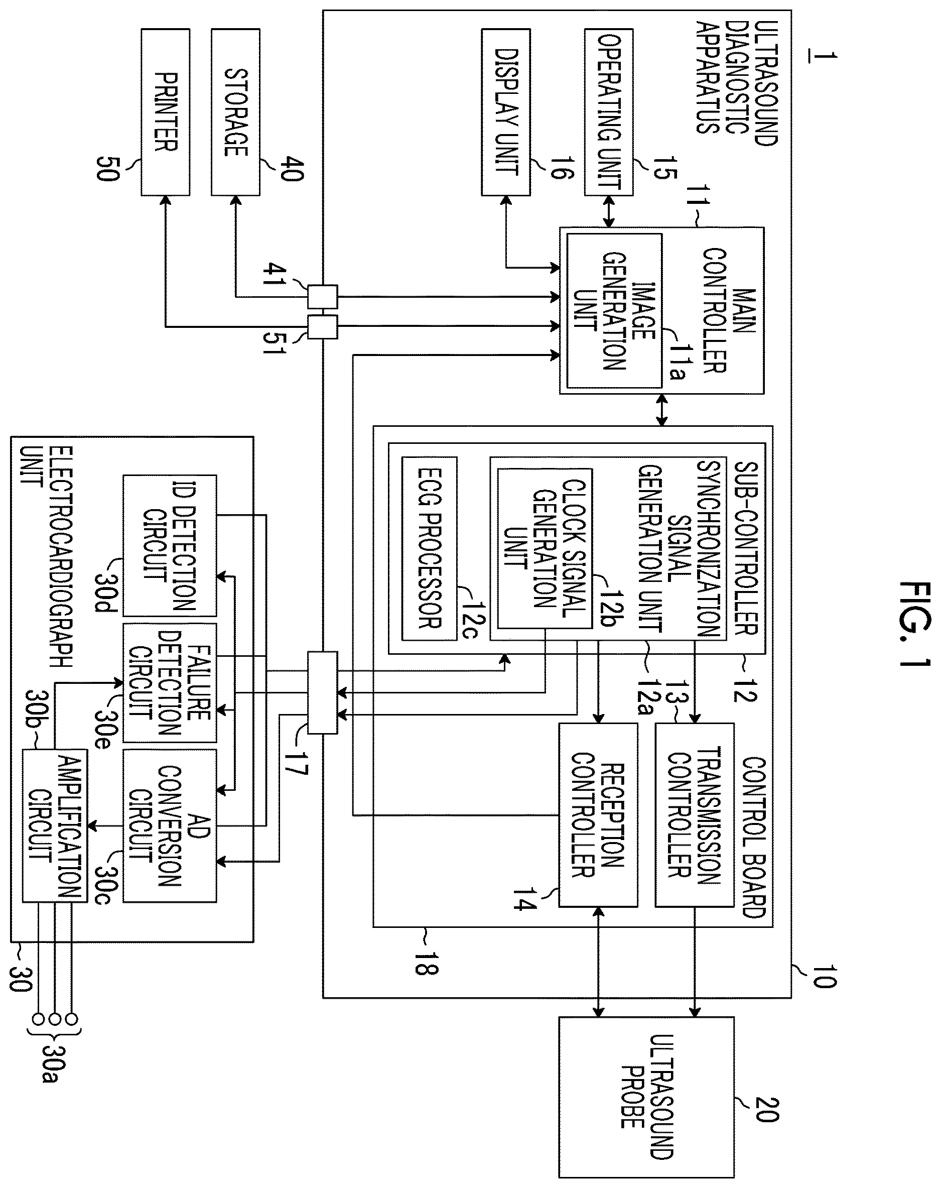
is a block diagram showing the schematic configuration of an ultrasound diagnostic system using a first embodiment of an ultrasound diagnostic apparatus of the invention.
is a block diagram showing the schematic configuration of the ultrasound diagnostic system using the first embodiment of the ultrasound diagnostic apparatus of the invention.
is an appearance perspective view of the ultrasound diagnostic system using the first embodiment of the ultrasound diagnostic apparatus of the invention.
is a timing chart of an ECG detection mode.
is a cross-sectional view including a center axis extending in a lengthwise direction of a puncture needle.
is a timing chart of a photoacoustic image mode.
is a diagram showing wirings of a connector of the first embodiment.
is a diagram showing the wirings of the connector of the first embodiment.
is a block diagram showing the schematic configuration of an ultrasound diagnostic system using a second embodiment of an ultrasound diagnostic apparatus of the invention.
is a block diagram showing the schematic configuration of an ultrasound diagnostic system using a second embodiment of an ultrasound diagnostic apparatus of the invention.
is a timing chart of a continuous wave Doppler measurement mode.
is a diagram showing wirings of a connector of the second embodiment.
is a diagram showing the wirings of the connector of the second embodiment.
is another timing chart of the photoacoustic image mode.
is a diagram showing an example of a photoacoustic image in a case where a photoacoustic wave is transmitted multiple times.
is a diagram illustrating processing of a photoacoustic image detected by transmitting a photoacoustic wave multiple times.
is a diagram showing an example of a photoacoustic image generated through the processing shown in .
DESCRIPTION OF THE PREFERRED EMBODIMENTS
Hereinafter, an ultrasound diagnostic system using a first embodiment of an ultrasound diagnostic apparatus of the invention will be described in detail referring to the drawings. are block diagrams showing the schematic configuration of an ultrasound diagnostic system 1 of the embodiment. is an appearance perspective view of the ultrasound diagnostic system 1 of the embodiment.
As shown in , the ultrasound diagnostic system 1 of the embodiment comprises an ultrasound diagnostic apparatus 10 , an ultrasound probe 20 , an electrocardiograph unit 30 , a photoacoustic wave light source unit 60 , a storage 40 , and a printer 50 .
In the ultrasound diagnostic system 1 shown in , the electrocardiograph unit 30 (corresponding to an electrocardiograph of the invention) is connected to a connector 17 of the ultrasound diagnostic apparatus 10 . As shown in , the connector 17 is configured such that the photoacoustic wave light source unit 60 (corresponding to a light source device of the invention) is also connectable. That is, the connector 17 of the ultrasound diagnostic apparatus 10 of the embodiment is configured such that both of the electrocardiograph unit 30 and the photoacoustic wave light source unit 60 are connectable, and one of these units is connected to the connector 17 . The configuration of the connector 17 will be described below in detail.
shows a state in which the photoacoustic wave light source unit 60 is connected to the connector 17 of the ultrasound diagnostic apparatus 10 . As shown in , the ultrasound diagnostic apparatus 10 of the embodiment is configured portable and is configured such that a cable of the ultrasound probe 20 is connected to a bottom surface of the ultrasound diagnostic apparatus 10 . The ultrasound diagnostic system 1 shown in is the same as the ultrasound diagnostic system 1 shown in except that, instead of the electrocardiograph unit 30 in the ultrasound diagnostic system 1 shown in , the photoacoustic wave light source unit 60 is connected to the connector 17 .
First, the ultrasound diagnostic apparatus 10 in the ultrasound diagnostic system 1 of the embodiment will be described. The ultrasound diagnostic apparatus 10 comprises a main controller 11 , a sub-controller 12 (corresponding to a controller of the invention), a transmission controller 13 , a reception controller 14 , an operating unit 15 , a display unit 16 , and the above-described connector 17 . The sub-controller 12 , the transmission controller 13 , and the reception controller 14 are provided on a control board 18 separate from the main controller 11 .
The main controller 11 controls the whole system, and comprises a central processing unit (CPU) and the like. The main controller 11 also comprises an image generation unit 11 a (corresponding to an ultrasound image generation unit of the invention). The image generation unit 11 a generates an ultrasound image and a photoacoustic image based on a detection signal detected by the ultrasound probe 20 . Generation processing of the ultrasound image and the photoacoustic image includes, for example, image reconstruction, such as phasing addition, detection, logarithmic conversion, and the like.
The sub-controller 12 comprises a processor and the like, and controls transmission of an ultrasonic wave from the ultrasound probe 20 and reception of a reflected ultrasonic wave reflected from a subject with the transmission of the ultrasonic to the subject. Furthermore, the sub-controller 12 controls reception of an electrocardiogram (ECG) signal output from the electrocardiograph unit 30 and controls emission of light from the photoacoustic wave light source unit 60 .
Specifically, the sub-controller 12 comprises a synchronization signal generation unit 12 a and an ECG processor 12 c . The synchronization signal generation unit 12 a comprises a clock signal generation unit 12 b.
The clock signal generation unit 12 b generates a clock signal, and comprises a quartz crystal resonator and the like. The synchronization signal generation unit 12 a comprises a phase locked loop (PLL) circuit and the like, and multiplies the clock signal generated in the clock signal generation unit 12 b to generate a synchronization signal. A frequency of the clock signal can be set to, for example, 40 MHz, and a frequency of the synchronization signal can be set to, for example, 160 MHz.
The synchronization signal generated in the synchronization signal generation unit 12 a is output to the transmission controller 13 and the reception controller 14 . The transmission controller 13 controls a transmission timing of the ultrasonic wave from the ultrasound probe 20 based on the input synchronization signal. The reception controller 14 controls a reception timing of the reflected ultrasonic wave of the ultrasound probe 20 based on the input synchronization signal. In the embodiment, the synchronization signal that is input to the transmission controller 13 and the reception controller 14 corresponds to a first synchronization signal of the invention. The transmission controller 13 and the reception controller 14 comprise an electric circuit that performs transmission and reception control described above, and the like.
The synchronization signal generated in the synchronization signal generation unit 12 a is output to the outside through the connector 17 and is input to the electrocardiograph unit 30 or the photoacoustic wave light source unit 60 connected to the connector 17 . The electrocardiograph unit 30 detects the ECG signal based on the input synchronization signal. The photoacoustic wave light source unit 60 controls an emission timing of light for generating a photoacoustic wave based on the input synchronization signal. In the embodiment, that synchronization signal that is input to the electrocardiograph unit 30 or the photoacoustic wave light source unit 60 corresponds to a second synchronization signal of the invention.
It is preferable that the processor of the main controller 11 having the image generation unit 11 a is operated based on a clock signal different from the clock signal generated by the clock signal generation unit 12 b of the sub-controller 12 . In this way, the clock signal of the processor of the main controller 11 and the clock signal of the processor of the sub-controller 12 are different, whereby there is no need to synchronize the main controller 11 and the sub-controller 12 , there is no need for a countermeasure against a circuitry delay or the like, and a simple configuration can be achieved. While the main controller 11 executes the generation processing of the ultrasound image and the photoacoustic image and storing the ultrasound image and the photoacoustic image to execute processing with no need for temporal synchronization with high accuracy, since various tasks are provided, the main controller 11 allocates the tasks with an operating system (OS) using a general-purpose CPU.
It should be noted that, in the control with the OS, a delay is likely to occur in a case where a load on the CPU increases, and the control with the OS is not suitable for synchronization with high accuracy. The sub-controller 12 needs for synchronization with high accuracy of transmission and reception control and the like. In the embodiment, the main controller 11 and the sub-controller 12 are independent. Accordingly, for example, even in a case where the load of the main controller 11 increases, since the sub-controller 12 performs digital control independently of the main controller 11 , it is possible continuously perform control with high accuracy.
The ECG processor 12 c receives the ECG signal detected based on the synchronization signal output from the synchronization signal generation unit 12 a and outputs the received ECG signal to the main controller 11 along with the timing at which the synchronization signal is transmitted to the electrocardiograph unit 30 . The main controller 11 makes the display unit 16 display the input ECG signal.
is a timing chart showing the synchronization signal that is output from the synchronization signal generation unit 12 a , a transmission timing of an ultrasonic wave based on the synchronization signal, a detection timing of the ECG signal, and a reception timing of the ultrasonic wave. An ultrasonic wave transmission timing signal shown in is a synchronization signal that is output from the synchronization signal generation unit 12 a to the transmission controller 13 , an ECG signal detection timing signal is a synchronization signal that is output from the synchronization signal generation unit 12 a to the electrocardiograph unit 30 , and an ultrasonic wave reception timing signal is a synchronization signal that is output from the synchronization signal generation unit 12 a to the reception controller 14 .
As shown in , the ultrasonic wave transmission timing signal, the ECG signal detection timing signal, and the ultrasonic wave reception timing signal are output at the same timing, and ultrasonic wave transmission and detection of the ECG signal are performed synchronously. The reception controller 14 starts reception of the reflected ultrasonic wave after a given delay time (for example, about 0.1 μs) from the timing at which the ultrasonic wave reception timing signal is received. Then, after the reflected ultrasonic wave is received in a given reception period, the reception controller 14 stops reception. The reception period can be set to a time (0.3 m×2/1540 m/s=0.39 ms; 1540 m/s is a sonic speed of an ultrasonic wave (10 MHz) to be transmitted) corresponding to a depth of about 30 cm, for example, taking a reverberation signal into consideration as well. Then, the reception controller 14 outputs a detection signal of the reflected ultrasonic wave to the main controller 11 along with the timing at which the ultrasonic wave reception timing signal is received. The ultrasound image is generated by the image generation unit 11 a of the main controller 11 based on the detection signal of the reflected ultrasonic wave. The main controller 11 makes the display unit 16 display the ultrasound image and an ECG waveform based on the ECG signal at the same timing.
Returning to , the operating unit 15 receives various operations of the user, and comprises a keyboard, operation buttons, and the like as shown in . The operating unit 15 of the embodiment receives ON and OFF operations of an ECG detection mode and ON and OFF operations of a photoacoustic image mode.
In a case where the ON operation of the ECG detection mode is received in the operating unit 15 , the synchronization signal generation unit 12 a outputs the ECG signal detection timing signal based on a control schedule set in advance. In a case where the ON operation of the photoacoustic image mode is received in the operating unit 15 , the synchronization signal generation unit 12 a outputs a photoacoustic wave transmission timing signal described below based on a control schedule set in advance.
The display unit 16 comprises a liquid crystal display or the like, and displays the ultrasound image and the photoacoustic image generated in the image generation unit 11 a , and the ECG waveform based on the ECG signal output from the ECG processor 12 c.
The ultrasound diagnostic apparatus 10 comprises USB connectors 41 and 51 different from the connector 17 . For example, the storage 40 is connected to the USB connector 41 , and for example, the printer 50 is connected to the USB connector 51 .
Next, the electrocardiograph unit 30 will be described. The electrocardiograph unit 30 comprises an electrode group 30 a that is mounted on the subject, an amplification circuit 30 b , an AD conversion circuit 30 c , an ID detection circuit 30 d , and a failure detection circuit 30 e.
The amplification circuit 30 b amplifies the ECG signal detected by the electrode group 30 a . The AD conversion circuit 30 c converts the ECG signal amplified by the amplification circuit 30 b to a digital signal and outputs the digital signal to the ultrasound diagnostic apparatus 10 . The AD conversion circuit 30 c operates in response to the ECG signal detection timing signal output from the synchronization signal generation unit 12 a and outputs the ECG signal to the ECG processor 12 c.
The ID detection circuit 30 d comprises a memory that stores ID information (corresponding to identification information for identifying the device) of the electrocardiograph unit 30 , a reading circuit that reads the ID information from the memory, and the like. The ID detection circuit 30 d outputs the ID information to the sub-controller 12 of the ultrasound diagnostic apparatus 10 when the electrocardiograph unit 30 is connected to the connector 17 of the ultrasound diagnostic apparatus 10 or when the ultrasound diagnostic apparatus 10 is started after the connection of the electrocardiograph unit 30 . As a method of detecting that the electrocardiograph unit 30 is connected to the ultrasound diagnostic apparatus 10 , various kinds of known connection detection can be used. For example, an optical sensor, such as a photocoupler, may be provided or detection may be performed with a mechanical configuration.
The sub-controller 12 performs ECG detection only in a case where the ECG detection mode is selected in the operating unit 15 and the ID information of the electrocardiograph unit 30 is received. That is, the sub-controller 12 outputs the ECG signal detection timing signal from the synchronization signal generation unit 12 a . Even though the ECG detection mode is selected in the operating unit 15 , in a case where ID information different from the ID information of the electrocardiograph unit 30 is received, the sub-controller 12 does not output the ECG signal detection timing signal.
Specifically, for example, in a case where the photoacoustic wave light source unit 60 , instead of the electrocardiograph unit 30 , is erroneously connected to the connector 17 , since the ID information of the electrocardiograph unit 30 is not received, the sub-controller 12 does not output the ECG signal detection timing signal. With this, it is possible to restrain failure in the photoacoustic wave light source unit 60 and erroneous emission of light from the photoacoustic wave light source unit 60 . In a case where the ECG detection mode is selected in the operating unit 15 , and in a case where a device other than the electrocardiograph unit 30 is connected to the connector 17 , the sub-controller 12 outputs the effect to the main controller 11 , and the main controller 11 makes the display unit 16 display a warning message or the like.
The failure detection circuit 30 e confirms whether or not there is failure in the electrocardiograph unit 30 when the electrocardiograph unit 30 is connected to the connector 17 of the ultrasound diagnostic apparatus 10 , when the ultrasound diagnostic apparatus 10 is started after the connection of the electrocardiograph unit 30 , or when the electrocardiograph unit 30 operates. As detection of failure in the electrocardiograph unit 30 , for example, an abnormality of output of the amplification circuit 30 b is detected. In a case where failure is detected by the failure detection circuit 30 e , a detection signal is output to the main controller 11 through the sub-controller 12 of the ultrasound diagnostic apparatus 10 , and the main controller 11 makes the display unit 16 displays the effect that failure is detected.
The AD conversion circuit 30 c , the ID detection circuit 30 d , and the failure detection circuit 30 e in the electrocardiograph unit 30 are subjected to digital control based on the clock signal generated in the clock signal generation unit 12 b of the ultrasound diagnostic apparatus 10 . In this way, the clock signal generation unit 12 b of the ultrasound diagnostic apparatus 10 is used, whereby there is no need provide a clock signal generation unit in the electrocardiograph unit 30 , and it is possible to achieve reduction in size.
Next, the photoacoustic wave light source unit 60 will be described. As shown in , the photoacoustic wave light source unit 60 comprises a light source unit 60 a , a pulse generation circuit 60 b , an ID detection circuit 60 c , and a failure detection circuit 60 d.
The light source unit 60 a emits light for generating a photoacoustic wave, and comprises a laser diode (LD), a light emitting diode (LED), or the like. The pulse generation circuit 60 b generates a pulse signal based on the synchronization signal output from the synchronization signal generation unit 12 a . The light source unit 60 a emits pulsed light in response to the pulse signal output from the pulse generation circuit 60 b.
One end of an optical cable 62 comprising an optical fiber is connected to the photoacoustic wave light source unit 60 , and a puncture needle 61 is connected to the other end of the optical cable 62 .
The puncture needle 61 is an embodiment of an insertion object of the invention, and is a needle that is punctured into the subject. is a cross-sectional view including a central axis extending in a lengthwise direction of the puncture needle 61 . The puncture needle 61 has an opening at a distal end formed at an acute angle, and includes a puncture needle body 61 a formed in a hollow shape, an optical fiber 61 b that guides light emitted from the photoacoustic wave light source unit 60 to the vicinity of the opening of the puncture needle 61 , and a photoacoustic wave generation unit 61 c that absorbs light emitted from the optical fiber 61 b to generate a photoacoustic wave.
The optical fiber 61 b and the photoacoustic wave generation unit 61 c are arranged in a hollow portion 61 d of the puncture needle body 61 a . The optical fiber 61 b is connected to the optical fiber in the optical cable 62 , for example, through an optical connector provided at a base end portion of the puncture needle 61 .
The photoacoustic wave generation unit 61 c is provided on a light emission side of the optical fiber 61 b , and is provided in the vicinity of the distal end of the puncture needle 61 and in an inner wall of the puncture needle body 61 a . The photoacoustic wave generation unit 61 c absorbs light emitted from the optical fiber 61 b to generate a photoacoustic wave. The photoacoustic wave generation unit 61 c is formed of, for example, epoxy resin mixed with a black pigment, polyurethane resin, fluororesin, silicon rubber, or the like. In , although the photoacoustic wave generation unit 61 c is drawn to be greater than the optical fiber 61 b , the invention is not limited thereto, and the photoacoustic wave generation unit 61 c may have a size similar to the diameter of the optical fiber 61 b.
The photoacoustic wave generation unit 61 c is limited to that described above, and a metal film or a film of an oxide having light absorbency with respect to the wavelength of light may be used as the photoacoustic wave generation unit. For example, as the photoacoustic wave generation unit 61 c , a film of an oxide, such as an iron oxide, a chromium oxide, or a manganese oxide, having high light absorbency with respect to the wavelength of light can be used. Alternatively, a metal film, such as titanium (Ti) or platinum (Pt) having lower light absorbency but higher biocompatibility than an oxide may be used as the photoacoustic wave generation unit 61 c . The position where the photoacoustic wave generation unit 61 c is provided is not limited to the inner wall of the puncture needle body 61 a . For example, the metal film or the film of the oxide as the photoacoustic wave generation unit 61 c may be formed on a light emission end of the optical fiber 61 b , for example, at a film thickness of about 100 nm by vapor deposition or the like such that the film of the oxide covers cover the light emission end. In this case, at least a part of light emitted from the light emission end of the optical fiber 61 b is absorbed by the metal film or the film of the oxide that covers the light emission end, and a photoacoustic wave is generated from the metal film or the film of the oxide.
Returning to , the ID detection circuit 60 c comprises a memory that stores ID information (corresponding to identification information for identifying the device) of the photoacoustic wave light source unit 60 , a reading circuit that reads the ID information from the memory, and the like. The ID detection circuit 60 c outputs the ID information to the sub-controller 12 of the ultrasound diagnostic apparatus 10 when the photoacoustic wave light source unit 60 is connected to the connector 17 of the ultrasound diagnostic apparatus 10 or when the ultrasound diagnostic apparatus 10 is started after the connection of the photoacoustic wave light source unit 60 . As a method of detecting that the photoacoustic wave light source unit 60 is connected to the ultrasound diagnostic apparatus 10 , various kinds of known connection detection can be used. For example, an optical sensor, such as a photocoupler, may be provided or detection may be performed with an electrical or mechanical configuration.
The sub-controller 12 performs photoacoustic image measurement only in a case where the photoacoustic image mode is selected in the operating unit 15 and the ID information of the photoacoustic wave light source unit 60 is received. That is, the photoacoustic wave transmission timing signal is output from the synchronization signal generation unit 12 a . Even though the photoacoustic image mode is selected in the operating unit 15 , in a case where ID information different from the ID information of the photoacoustic wave light source unit 60 is received, the sub-controller 12 does not output the photoacoustic wave transmission timing signal.
Specifically, for example, in a case where the electrocardiograph unit 30 , instead of the photoacoustic wave light source unit 60 , is erroneously connected to the connector 17 , since the ID information of the photoacoustic wave light source unit 60 is not received, the sub-controller 12 does not output the photoacoustic wave transmission timing signal. With this, it is possible to restrain failure in the electrocardiograph unit 30 . In a case where the photoacoustic image mode is selected in the operating unit 15 , and in a case where a device other than the photoacoustic wave light source unit 60 is connected to the connector 17 , the sub-controller 12 outputs the effect to the main controller 11 , and the main controller 11 makes the display unit 16 display a warning message or the like.
The failure detection circuit 60 d confirms whether or not there is failure in the photoacoustic wave light source unit 60 when the photoacoustic wave light source unit 60 is connected to the connector 17 of the ultrasound diagnostic apparatus 10 , when the ultrasound diagnostic apparatus 10 is started after the connection of the photoacoustic wave light source unit 60 , or when the photoacoustic wave light source unit 60 operates. As detection of failure in the photoacoustic wave light source unit 60 , for example, an abnormality of a current value or a voltage value of the light source unit 60 a is detected. In a case where failure is detected by the failure detection circuit 60 d , a detection signal is output to the main controller 11 through the sub-controller 12 of the ultrasound diagnostic apparatus 10 , and the main controller 11 makes the display unit 16 displays the effect that failure is detected.
The ID detection circuit 60 c and the failure detection circuit 60 d in the photoacoustic wave light source unit 60 are subjected to digital control based on the clock signal generated in the clock signal generation unit 12 b of the ultrasound diagnostic apparatus 10 . In this way, the clock signal generation unit 12 b of the ultrasound diagnostic apparatus 10 is used, whereby there is no need to provide a clock signal generation unit in the photoacoustic wave light source unit 60 , and it is possible to achieve reduction in size.
is a timing chart showing the synchronization signal that is output from the synchronization signal generation unit 12 a , a transmission timing of an ultrasonic wave based on the synchronization signal, a transmission timing of a photoacoustic wave, and a reception timing of the ultrasonic wave in the photoacoustic image mode. An ultrasonic wave transmission timing signal shown in is a synchronization signal (corresponding to a first synchronization signal of the invention) that is output from the synchronization signal generation unit 12 a to the transmission controller 13 , a photoacoustic wave transmission timing signal is a synchronization signal (corresponding to a second synchronization signal of the invention) that is output from the synchronization signal generation unit 12 a to the photoacoustic wave light source unit 60 , and an ultrasonic wave reception timing signal is a synchronization signal (corresponding to a first synchronization signal of the invention) that is output from the synchronization signal generation unit 12 a to the reception controller 14 .
As shown in , the ultrasonic wave transmission timing signal and the ultrasonic wave reception timing signal are output at the same timing excluding when the photoacoustic wave transmission timing signal and the ultrasonic wave reception timing signal are output simultaneously, and the photoacoustic wave transmission timing signal is output between the ultrasonic wave transmission timing signals. The reception controller 14 starts reception of the reflected ultrasonic wave after a given delay time (for example, about 0.1 μs) from the timing at which the ultrasonic wave reception timing signal is received. Then, after the reflected ultrasonic wave is received in a given reception period, the reception controller 14 stops reception. The reception period can be set to a time (0.3 m×2/1540 m/s=0.39 ms; 1540 m/s is a sonic speed of an ultrasonic wave (10 MHz)) corresponding to a depth of about 30 cm, for example, taking a reverberation signal into consideration as well. Then, the reception controller 14 outputs a detection signal of the reflected ultrasonic wave to the main controller 11 along with the timing at which the ultrasonic wave reception timing signal is received.
The reception controller 14 starts reception of the photoacoustic wave immediately after the photoacoustic wave is transmitted from the photoacoustic wave generation unit 61 c of the puncture needle 61 after the reception period of the reflected ultrasonic wave has elapsed. Then, the reception controller 14 stops reception after the photoacoustic wave is received in a given reception period. The reception period of the photoacoustic wave can be set to a time (0.3 m/1540 m/s=0.195 ms; 1540 m/s is a sonic speed of an ultrasonic wave (10 MHz)) corresponding to, for example, a depth of about 30 cm. The reception period of the photoacoustic wave becomes half the reception period of the reflected ultrasonic wave. Then, the reception controller 14 outputs a detection signal of the photoacoustic wave to the main controller 11 along with the timing at which the photoacoustic wave transmission timing signal is received. The image generation unit 11 a of the main controller 11 generates an ultrasound image based on the input detection signal of the ultrasonic wave and generates a photoacoustic image based on the input detection signal of the photoacoustic wave. Then, the main controller 11 makes the display unit 16 display the ultrasound image on the photoacoustic image in a superimposed manner.
An interval between transmission of the ultrasonic wave and reception of the reflected ultrasonic wave, and transmission and reception of the photoacoustic wave may be set to one line interval. That is, detection of the reflected ultrasonic wave and detection of the photoacoustic wave may be performed alternately per line. In this case, since transmission and reception can be made to correspond on a one-to-one basis, it is possible to implement the configuration with inexpensive hardware.
Detection of the reflected ultrasonic wave and detection of the photoacoustic wave may be performed alternately per frame. Alternatively, detection of the reflected ultrasonic wave and detection of the photoacoustic wave may be performed alternately per a plurality of lines. Specifically, for example, in a case where one frame has 128 lines, detection of the reflected ultrasonic wave of the first to 64th lines may be performed, and then, detection of the photoacoustic wave of the first to 64th lines may be performed. Subsequently, detection of the reflected ultrasonic wave of the 65th to 128th lines may be performed, and then, detection of the photoacoustic wave of the 65th to 128th lines may be performed.
Next, the connector 17 of the ultrasound diagnostic apparatus 10 will be described. shows a state in which the electrocardiograph unit 30 is connected to the connector 17 , and shows a state in which the photoacoustic wave light source unit 60 is connected to the connector 17 . The connector 17 of the embodiment has five wirings 17 a to 17 e as shown in .
The first wiring 17 a is a power line, and electric power is supplied from the ultrasound diagnostic apparatus 10 to the electrocardiograph unit 30 or the photoacoustic wave light source unit 60 through the first wiring 17 a . The second wiring 17 b is a clock signal line, and the clock signal is supplied from the ultrasound diagnostic apparatus 10 to the electrocardiograph unit 30 or the photoacoustic wave light source unit 60 through the second wiring 17 b . The third wiring 17 c is a synchronization signal line, and the synchronization signal is transmitted from the ultrasound diagnostic apparatus 10 to the electrocardiograph unit 30 or the photoacoustic wave light source unit 60 through the third wiring 17 c.
The fourth wiring 17 d is a data line, and the ECG signal, the ID information, and the failure detection signal output from the electrocardiograph unit 30 are input to the ultrasound diagnostic apparatus 10 through the fourth wiring 17 d . Furthermore, the ID information and the failure detection signal output from the photoacoustic wave light source unit 60 are input to the ultrasound diagnostic apparatus 10 through the fourth wiring 17 d . In , although the fourth wiring 17 d is shown by one line, it is preferable that the fourth wiring 17 d has two or three lines to perform parallel transmission.
The fifth wiring 17 e is a ground line, and a ground potential is supplied from the ultrasound diagnostic apparatus 10 to the electrocardiograph unit 30 or the photoacoustic wave light source unit 60 through the fifth wiring 17 e.
With the ultrasound diagnostic system 1 of the first embodiment described above, a configuration is made in which the ultrasound probe 20 is controlled based on the synchronization signal generated by the synchronization signal generation unit 12 a , the connector 17 having the synchronization signal line transmitting the synchronization signal generated by the synchronization signal generation unit 12 a is provided, and the photoacoustic wave light source unit 60 is connectable to the connector 17 . For this reason, it is possible to synchronize emission of light from the photoacoustic wave light source unit 60 and reception in the ultrasound probe 20 with high accuracy.
Furthermore, a configuration in which both of the electrocardiograph unit 30 and the photoacoustic wave light source unit 60 are connectable to the connector 17 is made. Accordingly, it is possible to reduce the space of the connector, and to achieve reduction in size. In addition, it is possible to restrain deterioration of electrical safety and electromagnetic compatibility (EMC) performance due to an increase in the number of connectors.
In the first embodiment described above, although the electrocardiograph unit 30 is connectable to the connector 17 of the ultrasound diagnostic apparatus 10 , a configuration in which a phonocardiograph unit (corresponding to a phonocardiograph of the invention) may be connectable to the connector 17 of the ultrasound diagnostic apparatus 10 may be made. The phonocardiograph unit is configured by providing a microphone for cardiac sound measurement instead of the electrode group 30 a of the electrocardiograph unit 30 .
There is no case where ECG detection and phonocardiogram (PCG) detection, and photoacoustic image measurement (puncture) are simultaneously used clinically. For this reason, there are no problems in particular even though the electrocardiograph unit 30 and the phonocardiograph unit, and the photoacoustic wave light source unit 60 are connected to the connector 17 exclusively.
Next, an ultrasound diagnostic system using a second embodiment of an ultrasound diagnostic apparatus of the invention will be described. are block diagrams showing the schematic configuration of an ultrasound diagnostic system 2 of the embodiment. The appearance of the ultrasound diagnostic system 2 of the embodiment is the same as the ultrasound diagnostic system 1 of the first embodiment shown in .
In the ultrasound diagnostic system 1 of the first embodiment described above, a configuration in which the electrocardiograph unit 30 and the photoacoustic wave light source unit 60 are connectable to the connector 17 is made. The ultrasound diagnostic system 2 of the second embodiment comprises a connector 19 configured such that both of a probe 70 for continuous wave Doppler measurement and the photoacoustic wave light source unit 60 are connectable. shows a state in which the probe 70 for continuous wave Doppler measurement is connected to the connector 19 of the ultrasound diagnostic apparatus 10 . shows a state in which the photoacoustic wave light source unit 60 is connected to the connector 19 . The ultrasound diagnostic system 2 shown in is the same as the ultrasound diagnostic system 1 shown in except that, instead of the probe 70 for continuous wave Doppler measurement in the ultrasound diagnostic system 2 shown in , the photoacoustic wave light source unit 60 is connected to the connector 19 .
First, the ultrasound diagnostic apparatus 10 in the ultrasound diagnostic system 2 of the embodiment will be described. The ultrasound diagnostic apparatus 10 of the embodiment comprises a continuous wave (CW) dedicated transmission controller 71 and a CW dedicated reception controller 72 instead of the ECG processor 12 c of the ultrasound diagnostic apparatus 10 of the first embodiment.
The CW dedicated transmission controller 71 generates a CW dedicated transmission signal based on the synchronization signal output from the synchronization signal generation unit 12 a and transmits the CW dedicated transmission signal to the probe 70 for continuous wave Doppler measurement through the connector 19 . The probe 70 for continuous wave Doppler measurement makes an ultrasonic wave of continuous waves be transmitted from the detection element 70 a for transmission to the subject in response to the CW dedicated transmission signal.
The CW dedicated reception controller 72 performs reception control of a reflected ultrasonic wave reflected from the subject with transmission of the ultrasonic wave of the continuous waves to the subject based on the synchronization signal output from the synchronization signal generation unit 12 a.
In a case where the probe 70 for continuous wave Doppler measurement is connected to the connector 19 , the image generation unit 11 a in the main controller 11 receives a detection signal output from a detection element 70 b for reception of probe 70 for continuous wave Doppler measurement and generates a CW Doppler image based on the detection signal.
The CW dedicated transmission controller 71 and the CW dedicated reception controller 72 comprise an electric circuit that performs transmission and reception control described above, and the like.
As in the first embodiment, the sub-controller 12 controls transmission of the ultrasonic wave from the ultrasound probe 20 and reception of the reflected ultrasonic wave reflected from the subject with transmission of the ultrasonic wave to the subject. Furthermore, the sub-controller 12 controls transmission of the ultrasonic wave of the continuous waves from the probe 70 for continuous wave Doppler measurement described above and reception of the reflected ultrasonic wave reflected from the subject with transmission of the ultrasonic wave to the subject. In addition, as in the first embodiment, the sub-controller 12 controls emission of light from the photoacoustic wave light source unit 60 .
The configurations of the synchronization signal generation unit 12 a and the clock signal generation unit 12 b in the sub-controller 12 are the same as those in the first embodiment.
The operating unit 15 of the embodiment receives ON and OFF operations of a continuous wave Doppler measurement mode and ON and OFF operations of the photoacoustic image mode.
In a case where the ON operation of the continuous wave Doppler measurement mode is received in the operating unit 15 , the synchronization signal generation unit 12 a outputs a CW dedicated transmission timing signal and a CW dedicated reception timing signal described below based on a control schedule set in advance. In a case where the ON operation of the photoacoustic image mode is received in the operating unit 15 , the synchronization signal generation unit 12 a outputs a photoacoustic wave transmission timing signal based on a control schedule set in advance.
Next, the probe 70 for continuous wave Doppler measurement will be described. The probe 70 for continuous wave Doppler measurement comprises the detection element 70 a for transmission, the detection element 70 b for reception, an ID detection circuit 70 c , and a failure detection circuit 70 d.
The detection element 70 a for transmission is configured of a piezoelectric element or the like, and transmits the ultrasonic wave of the continuous waves to the subject. The detection element 70 b for reception is also configured of a piezoelectric element or the like, and receives the reflected ultrasonic wave reflected from the subject with transmission of the ultrasonic wave of the continuous waves.
The ID detection circuit 70 c comprises a memory that stores ID information of the probe 70 for continuous wave Doppler measurement, a reading circuit that reads the ID information from the memory, and the like. The ID detection circuit 70 c outputs the ID information to the sub-controller 12 of the ultrasound diagnostic apparatus 10 when the probe 70 for continuous wave Doppler measurement is connected to the connector 19 of the ultrasound diagnostic apparatus 10 or when the ultrasound diagnostic apparatus 10 is started after the connection of the probe 70 for continuous wave Doppler measurement.
The sub-controller 12 performs continuous wave Doppler measurement only in a case where the ID information of the probe 70 for continuous wave Doppler measurement is received. As a method of detecting that the probe 70 for continuous wave Doppler measurement is connected to the ultrasound diagnostic apparatus 10 , various kinds of known connection detection can be used. For example, an optical sensor, such as a photocoupler, may be provided or detection may be performed with a mechanical configuration.
The sub-controller 12 performs continuous wave Doppler measurement only in a case where the continuous wave Doppler measurement mode is selected in the operating unit 15 and the ID information of the probe 70 for continuous wave Doppler measurement is received. That is, the CW dedicated transmission timing signal and the CW dedicated reception timing signal are output from the synchronization signal generation unit 12 a . Even though the continuous wave Doppler measurement mode is selected in the operating unit 15 , in a case where ID information different from the ID information of the probe 70 for continuous wave Doppler measurement is received, the sub-controller 12 does not output the CW dedicated transmission timing signal and the CW dedicated reception timing signal.
Specifically, for example, in a case where the photoacoustic wave light source unit 60 , instead of the probe 70 for continuous wave Doppler measurement, is erroneously connected to the connector 19 , since the ID information of the probe 70 for continuous wave Doppler measurement is not received, the sub-controller 12 does not output the CW dedicated transmission timing signal and the CW dedicated reception timing signal. With this, it is possible to restrain failure in the photoacoustic wave light source unit 60 and erroneous emission of light from the photoacoustic wave light source unit 60 . In a case where the continuous wave Doppler measurement mode is selected in the operating unit 15 , and in a case where a device other than the probe 70 for continuous wave Doppler measurement is connected to the connector 19 , the sub-controller 12 outputs the effect to the main controller 11 , and the main controller 11 makes the display unit 16 display a warning message or the like.
The failure detection circuit 70 d confirms whether or not there is failure in the probe 70 for continuous wave Doppler measurement when the probe 70 for continuous wave Doppler measurement is connected to the connector 19 of the ultrasound diagnostic apparatus 10 , when the ultrasound diagnostic apparatus 10 is started after the connection of the probe 70 for continuous wave Doppler measurement, or when the probe 70 for continuous wave Doppler measurement operates. As detection of failure in the probe 70 for continuous wave Doppler measurement, for example, detection of short-circuit or open circuit of the wirings of the detection element 70 a for transmission and the detection element 70 b for reception, or the like is exemplified. In a case where failure is detected by the failure detection circuit 70 d , a detection signal is output to the main controller 11 through the sub-controller 12 of the ultrasound diagnostic apparatus 10 , and the main controller 11 makes the display unit 16 display the effect that failure is detected.
The ID detection circuit 70 c and the failure detection circuit 70 d in the probe 70 for continuous wave Doppler measurement are subjected to digital control based on the clock signal generated in the clock signal generation unit 12 b of the ultrasound diagnostic apparatus 10 . In this way, the clock signal generation unit 12 b of the ultrasound diagnostic apparatus 10 is used, whereby there is no need to provide a clock signal generation unit in the probe 70 for continuous wave Doppler measurement, and it is possible to achieve reduction in size.
is a timing chart showing the synchronization signal that is output from the synchronization signal generation unit 12 a , a transmission timing of the ultrasonic wave of the continuous waves based on the synchronization signal, and the reception timing of the ultrasonic wave. Measurement of the ultrasound image in the ultrasound probe 20 and continuous wave Doppler measurement in the probe 70 for continuous wave Doppler measurement are not simultaneously performed, and only one of measurement of the ultrasound image and continuous wave Doppler measurement is performed. For this reason, in , the ultrasonic wave transmission timing signal and the ultrasonic wave reception timing signal remain zero.
The CW dedicated transmission timing signal shown in is a synchronization signal (corresponding to a second synchronization signal of the invention) that is output from the synchronization signal generation unit 12 a to the CW dedicated transmission controller 71 , the CW dedicated reception timing signal is a synchronization signal (corresponding to a second synchronization signal of the invention) that is output from the synchronization signal generation unit 12 a to the CW dedicated reception controller 72 , the CW dedicated transmission signal is a control signal (corresponding to a signal generated based on a second synchronization signal of the invention) that is output from the CW dedicated transmission controller 71 to the detection element 70 a for transmission, and a CW dedicated reception signal is a control signal (corresponding to a signal generated based on a second synchronization signal of the invention) that is output from the CW dedicated reception controller 72 to the detection element 70 b for reception.
As shown in , the CW dedicated transmission timing signal and the CW dedicated reception timing signal are output at the same timing. The CW dedicated transmission controller 71 outputs the CW dedicated transmission signal having continuous pulse waves to the detection element 70 a for transmission in response to the input CW dedicated transmission timing signal. The detection element 70 a for transmission transmits the ultrasonic wave of the continuous waves to the subject in response to the input CW dedicated transmission signal.
The CW dedicated reception controller 72 outputs the CW dedicated reception signal to the detection element 70 b for reception in response to the input CW dedicated reception timing signal. The detection element 70 b for reception continuously performs reception of the ultrasonic wave in response to the CW dedicated reception signal. A detection signal detected by the detection element 70 b for reception is received by the CW dedicated reception controller 72 and is then output to the main controller 11 . Then, in the image generation unit Ila of the main controller 11 , a continuous wave Doppler measurement image is generated based on the input detection signal and is displayed on the display unit 16 .
Next, the operation in a case where the photoacoustic wave light source unit 60 is connected to the connector 19 of the ultrasound diagnostic apparatus 10 will be described. The configuration of the photoacoustic wave light source unit 60 itself is the same as that in the first embodiment described above.
In the embodiment, the control signal (corresponding to a signal generated based on a second synchronization signal of the invention) is output from the CW dedicated transmission controller 71 to the pulse generation circuit 60 b in response to the synchronization signal output from the synchronization signal generation unit 12 a , and the pulse generation circuit 60 b generates a pulse signal based on the input control signal. Then, as in the first embodiment, the light source unit 60 a emits pulsed light in response to the pulse signal output from the pulse generation circuit 60 b . The CW dedicated transmission controller 71 outputs the control signal using monopolar transmission.
Even in the embodiment, the ON and OFF operations of the photoacoustic image mode are received by the operating unit 15 . In a case where the ON operation of the photoacoustic image mode is received in the operating unit 15 , the synchronization signal generation unit 12 a outputs the synchronization signal based on a control schedule set in advance. In the photoacoustic image mode, as in the first embodiment, while ultrasound image measurement and photoacoustic image measurement are performed alternately, the synchronization signal that is output from the synchronization signal generation unit 12 a , the transmission timing of the ultrasonic wave based on the synchronization signal, the transmission timing of the photoacoustic wave, and the reception timing of the ultrasonic wave are the same as those in the timing chart shown in . The operation of the ID detection circuit 70 c and the failure detection circuit 70 d in the photoacoustic wave light source unit 60 is the same as that in the above-described embodiment.
In a case where the ON operation of the photoacoustic image mode is received in the operating unit 15 , continuous wave Doppler measurement is not performed.
Next, the connector 19 of the ultrasound diagnostic apparatus 10 will be described. shows a state in which the probe 70 for continuous wave Doppler measurement is connected to the connector 19 , and shows a state in which the photoacoustic wave light source unit 60 is connected to the connector 19 . The connector 19 of the embodiment has five wirings 19 a to 19 e as shown in .
The first wiring 19 a is a synchronization signal line (also referred to as a transmission signal line), and in the continuous wave Doppler measurement mode, the CW dedicated transmission signal is transmitted from the ultrasound diagnostic apparatus 10 to the detection element 70 a for transmission through the first wiring 19 a . In the photoacoustic image mode, the photoacoustic wave transmission timing signal is transmitted from the ultrasound diagnostic apparatus 10 to the pulse generation circuit 60 b through the first wiring 19 a.
The second wiring 19 b is a clock signal line, and the clock signal is supplied from the ultrasound diagnostic apparatus 10 to the probe 70 for continuous wave Doppler measurement or the photoacoustic wave light source unit 60 through the second wiring 19 b.
The third wiring 19 c is a data line, and the ID information and the failure detection signal output from the probe 70 for continuous wave Doppler measurement are input to the ultrasound diagnostic apparatus 10 through the third wiring 19 c . Furthermore, the ID information and the failure detection signal output from the photoacoustic wave light source unit 60 are input to the ultrasound diagnostic apparatus 10 through the third wiring 19 c . In , although the third wiring 19 c is shown by one line, it is preferable that the third wiring 19 c has two lines to perform parallel transmission.
The fourth wiring 19 d is a ground line, and a ground potential is supplied from the ultrasound diagnostic apparatus 10 to the probe 70 for continuous wave Doppler measurement or the photoacoustic wave light source unit 60 through the fourth wiring 19 d.
The fifth wiring 19 e is a detection signal line (also referred to as a reception signal line), and the detection signal (also referred to as a reception signal) detected by the detection element 70 b for reception of the probe 70 for continuous wave Doppler measurement is output to the CW dedicated reception controller 72 through the fifth wiring 19 e.
With the ultrasound diagnostic system 2 of the second embodiment described above, a configuration is made in which the ultrasound probe 20 is controlled based on the synchronization signal generated by the synchronization signal generation unit 12 a , the connector 19 having the synchronization signal line transmitting the synchronization signal generated by the synchronization signal generation unit 12 a is provided, and both of the probe 70 for continuous wave Doppler measurement and the photoacoustic wave light source unit 60 are connectable to the connector 19 . Accordingly, it is possible to reduce the space of the connector, and to achieve reduction in size. In addition, it is possible to restrain deterioration of electrical safety and EMC performance due to an increase in the number of connectors.
The probe 70 for continuous wave Doppler measurement is a device for circulatory diagnosis, and is not used simultaneously with the photoacoustic image (puncture) clinically. Accordingly, there are no problems in particular even though the probe 70 for continuous wave Doppler measurement and the photoacoustic wave light source unit 60 are connected to the connector 19 exclusively.
In the first and second embodiments described above, although a configuration in which two devices are connectable to one connector is made, three or more devices may be connectable to one connector. For example, a configuration in which the photoacoustic wave light source unit 60 , the electrocardiograph unit 30 , and the probe 70 for continuous wave Doppler measurement are connectable to one connector may be made.
In the first and second embodiments described above, although one connector is shared by two devices, the invention is not limited thereto, the connector 17 of the first embodiment or the connector 19 of the second embodiment may be a connector dedicated to the photoacoustic wave light source unit 60 .
In the first and second embodiments described above, although, in the photoacoustic image mode, the photoacoustic wave is transmitted once at one ultrasonic wave reception interval (between the ultrasonic wave reception timing signals) as shown in , the invention is not limited thereto, and as shown in , a delay interval ΔT may be provided and the photoacoustic wave may be transmitted multiple times. In a case where the delay interval ΔT is set to, for example, 0.24 μs, 1540 m/s×0.24 μs=0.36 mm. Accordingly, in this case, as shown in , an image in which an image of the photoacoustic wave generation unit 61 c at the distal end of the puncture needle 61 is arranged at two points at an interval of 0.36 mm in a depth direction is displayed. With this, it is possible to improve visibility of the distal end of the puncture needle 61 .
There is a need to secure an interval during which the occurrence of an initial photoacoustic wave ends, and it is preferable that the delay interval ΔT is equal to or greater than 0.05 μs. The ultrasonic wave reception interval may be an interval during which a signal of one line is detected by the ultrasound probe 20 or may be an interval during which a signal of one frame is detected by the ultrasound probe 20 .
A photoacoustic image time-advanced by ΔT with respect to the photoacoustic image detected by providing the delay interval ΔT and transmitting the photoacoustic wave multiple times as described above, and the original photoacoustic image and the time-advanced photoacoustic image may be added to generate an added photoacoustic image. Then, threshold value processing may be executed on the added photoacoustic image using a threshold value that is about half a maximum value, making a signal equal to or less than the threshold value be equal to or less than half. is a schematic view in which the above-described processing is arranged in time series. In , the processing progresses from left to right. A portion a of shows a photoacoustic image detected with transmission of an initial photoacoustic wave, a portion b of shows a photoacoustic image detected with transmission of a second photoacoustic wave, and a portion c of shows a photoacoustic image time-advanced by ΔT. A portion d of shows a photoacoustic image after the above-described threshold value processing is executed. With this, it is possible to more clearly display the distal end position of the puncture needle 61 . In the embodiment, as shown in , since an initial photoacoustic wave transmission timing signal and the ultrasonic wave reception timing signal are the same timing, the photoacoustic image with transmission of the initial photoacoustic wave indicates the real distal end of the puncture needle 61 .
The invention is not limited to the flow of the processing shown in , and correlation filtering processing may be executed to generate the same photoacoustic image as the photoacoustic image that is generated through the processing shown in .
In the first and second embodiments described above, although the ultrasound diagnostic apparatus 10 is portable, the invention is not limited to a portable ultrasound diagnostic apparatus, and may also be applied to a stationary ultrasound diagnostic apparatus.
In the first and second embodiments described above, although the puncture needle 61 is used as an embodiment of the insertion object of the invention, the invention is not limited thereto. The insertion object may be a needle for radiofrequency ablation that houses an electrode for use in radiofrequency ablation, a catheter that is inserted into a blood vessel, or a guide wire of the catheter that is inserted into the blood vessel. Alternatively, an optical fiber for laser treatment may be applied.
Although the invention has been described above based on the preferred embodiments, the insertion object and the photoacoustic measurement device of the invention are not limited only to the above-described embodiments, and various corrections and alterations in the configurations of the above-described embodiments are also included in the scope of the invention.
EXPLANATION OF REFERENCES
•
• 1 , 2 : ultrasound diagnostic system • 10 : ultrasound diagnostic apparatus • 11 : main controller • 11 a : image generation unit • 12 : sub-controller • 12 a : synchronization signal generation unit • 12 b : clock signal generation unit • 12 c : ECG processor • 13 : transmission controller • 14 : reception controller • 15 : operating unit • 16 : display unit • 17 : connector • 17 a : first wiring • 17 b : second wiring • 17 c : third wiring • 17 d : fourth wiring • 17 e : fifth wiring • 18 : control board • 19 : connector • 19 a : first wiring • 19 b : second wiring • 19 c : third wiring • 19 d : fourth wiring • 19 e : fifth wiring • 20 : ultrasound probe • 30 : electrocardiograph unit • 30 a : electrode group • 30 b : amplification circuit • 30 c : AD conversion circuit • 30 d : ID detection circuit • 30 e : failure detection circuit • 40 : storage • 41 , 51 : USB connector • 50 : printer • 60 : photoacoustic wave light source unit • 60 a : light source unit • 60 b : pulse generation circuit • 60 c : ID detection circuit • 60 d : failure detection circuit • 61 : puncture needle • 61 a : puncture needle body • 61 b : optical fiber • 61 c : photoacoustic wave generation unit • 61 d : hollow portion • 62 : optical cable • 70 : probe for continuous wave Doppler measurement • 70 a : detection element for transmission • 70 b : detection element for reception • 70 c : ID detection circuit • 70 d : failure detection circuit • 71 : CW dedicated transmission controller • 72 : CW dedicated reception controller • ΔT: delay interval
Figures (13)
Citations
This patent cites (26)
- US5957846
- US2004/0116813
- US2004/0131299
- US2009/0088821
- US2013/0141557
- US2014/0187902
- US2015/0038845
- US2015/0182124
- US2015/0297092
- US2016/0136689
- US2016/0206284
- US2016/0303354
- US2017/0014053
- US2017/0112386
- US2018/0078235
- US104337500
- US104902823
- US105796127
- US106361290
- US106470614
- US2015231582
- US2016-64010
- US10-2016-0114012
- USWO 2014/017044
- USWO 2016/0061
- USWO 2017/002338