Lid Moving Systems and Methods for Chambers and Containers
Abstract
Lid moving systems and methods facilitate reliable and safe movement of lids for chambers. Such systems may include: (a) a base member; (b) side walls extending from the base member with each including a cam surface defined therein; (c) a lid mounting arm extending away from the base member; (d) a first pivotal connection system engaging the cam surfaces and pivotally engaging the lid mounting arm; (e) a traveler member including a recess or opening on a surface facing the base member; (f) a second pivotal connection system pivotally engaging the traveler member with the lid mounting arm; (g) a motor for moving the traveler member (causing movement of the lid mounting arm with respect to the side walls); and/or (h) a stopper mechanism extending into the recess or opening of the traveler member from a direction of the surface facing the base member when the lid is opened.
Claims (22)
1 . A lid moving system, comprising: a base member having a first side and a second side; a first side wall extending from the first side of the base member, the first side wall including a first cam surface defined therein; a second side wall extending from the second side of the base member, the second side wall including a second cam surface defined therein; a lid mounting arm extending in a direction away from the base member; a first pivotal connection system engaging the first cam surface and the second cam surface and pivotally engaging the lid mounting arm; a traveler member including a recess or opening on a surface facing the base member; a second pivotal connection system pivotally engaging the traveler member with the lid mounting arm; a motor for moving the traveler member, wherein movement of the traveler member causes movement of the lid mounting arm with respect to the first side wall and the second side wall; and a stopper mechanism configured to removably extend into the recess or opening of the traveler member from a direction of the surface facing the base member when the traveler member is at a lid open position.
7 . An enclosure, comprising: a main body member including a top, a bottom, and one or more sidewalls connecting the top and the bottom, wherein the top includes an opening providing access to an internal chamber defined in part by the main body member; a lid sealingly attachable to the top of the main body member to close the internal chamber; and a lid moving system engaged with the main body member, wherein the lid moving system includes: a base member having a first side and a second side, wherein the base member includes a surface that faces in a direction away from the main body member, a first side wall extending from the first side of the base member, the first side wall including a first cam surface defined therein, a second side wall extending from the second side of the base member, the second side wall including a second cam surface defined therein, a lid mounting arm extending in a direction away from the base member, wherein the lid mounting arm is engaged with the lid at a first outer edge location of the lid, a first pivotal connection system engaging the first cam surface and the second cam surface and pivotally engaging the lid mounting arm, a traveler member including a recess or opening on a surface facing the base member, a second pivotal connection system pivotally engaging the traveler member with the lid mounting arm, a motor for moving the traveler member, wherein movement of the traveler member causes movement of the lid mounting arm and the lid with respect to the main body member, and a stopper mechanism configured to extend into the recess or opening of the traveler member from a direction of the surface facing the base member when the traveler member is at a lid open position.
16 . A method of moving a lid with respect to a main body member of an enclosure, the method comprising: engaging a lid moving system with the lid, wherein the lid moving system includes: a base member having a surface that faces in a direction away from the main body member, a lid mounting arm extending in a direction away from the base member, wherein the engaging includes engaging the lid mounting arm with the lid at a first outer edge location of the lid, a traveler member including a recess or opening on a surface facing the base member, a pivotal connection system pivotally engaging the traveler member with the lid mounting arm, and a motor for moving the traveler member, wherein movement of the traveler member causes movement of the lid mounting arm and the lid; operating the motor to initially apply a lifting force to the lid at the first outer edge location; after the lifting force is applied, operating the motor to apply a rotational force to rotate the lid upward on the lid mounting arm in a direction away from the main body member to a lid open position; and inserting a stopper mechanism into the recess or opening of the traveler member from a direction of the surface facing the base member to prevent the lid from moving from the lid open position.
Show 19 dependent claims
2 . The lid moving system according to claim 1 , wherein the base member includes a through hole aperture, and wherein the stopper mechanism is removably engageable with the recess or opening of the traveler member through the through hole aperture of the base member when the traveler member is at the lid open position.
3 . The lid moving system according to claim 1 , further comprising a heating element configured to heat at least a portion of the lid mounting arm.
4 . The lid moving system according to claim 1 , wherein each of the first cam surface and the second cam surface has a vertical cam segment at a first end and an angled cam segment extending upward and away from the vertical cam segment and away from the base member.
5 . The lid moving system according to claim 1 , wherein each of the first side wall and the second side wall includes a tracking slot to define a direction of motion for the traveler member, and wherein the traveler member includes one or more tracking elements extending into the tracking slots.
6 . The lid moving system according to claim 1 , wherein the lid mounting arm includes a first end and a lid-engaging portion, wherein the first pivotal connection system is located at the first end and the second pivotal connection system is spaced from the first end toward the lid-engaging portion.
8 . The enclosure according to claim 7 , wherein the base member includes a through hole aperture, and wherein the stopper mechanism is removably engageable with the recess or opening of the traveler member through the through hole aperture of the base member when the traveler member is at the lid open position.
9 . The enclosure according to claim 7 , further comprising a control system for controlling the motor, wherein the control system generates signals to stop operation of the motor when the lid is at the lid open position.
10 . The enclosure according to claim 7 , further comprising a heating element configured to heat at least one of (i) the lid at least at the first outer edge location or (ii) at least a portion of the lid mounting arm.
11 . The enclosure according to claim 7 , wherein each of the first cam surface and the second cam surface has a vertical cam segment at a first end and an angled cam segment extending upward and away from the vertical cam segment and away from the base member.
12 . The enclosure according to claim 7 , wherein each of the first cam surface and the second cam surface is configured such that, during a lid opening event: (i) the lid moving system initially lifts the lid upward at the first outer edge location until a seal between the lid and the main body member is unsealed and then (ii) the lid pivots upward away from the main body member about the first pivotal connection system and the second pivotal connection system.
13 . The enclosure according to claim 7 , wherein each of the first side wall and the second side wall includes a tracking slot to define a direction of motion for the traveler member, and wherein the traveler member includes one or more tracking elements extending into the tracking slots.
14 . The enclosure according to claim 7 , wherein the lid mounting arm includes a first end and a lid-engaging portion, wherein the first pivotal connection system is located at the first end and the second pivotal connection system is spaced from the first end toward the lid-engaging portion.
15 . The enclosure according to claim 7 , wherein the main body member comprises a substrate handling chamber for moving substrates from the internal chamber to one or more substrate processing chambers.
17 . The method according to claim 16 , wherein the inserting includes inserting the stopper mechanism through a through hole opening provided in the base member and into the recess or opening of the traveler member.
18 . The method according to claim 16 , wherein the lifting force breaks a sealed engagement between the lid and the main body member at the first outer edge location.
19 . The method according to claim 18 , wherein application of the lifting force to break the sealed engagement includes deforming a shape of the lid at the first outer edge location.
20 . The method according to claim 16 , further comprising heating at least one of (i) the lid at least at the first outer edge location or (ii) at least a portion of the lid mounting arm prior to operating the motor to apply the lifting force.
21 . The method according to claim 16 , wherein the main body member comprises a substrate handling chamber for moving substrates from the main body member to one or more substrate processing chambers.
22 . The method according to claim 16 , wherein with the lid starting in the lid open position, the method further comprises: removing the stopper mechanism from the recess or opening of the traveler member; and operating the motor to initially rotate the lid downward on the lid mounting arm in a direction toward the main body member and then move the lid downward to the main body member.
Full Description
Show full text →
CROSS-REFERENCE TO RELATED APPLICATION(S)
This application claims the benefit of U.S. Provisional Application 63/526,759 filed on Jul. 14, 2023, the entire contents of which are incorporated herein by reference.
FIELD OF THE DISCLOSURE
The present disclosure relates generally to systems and methods for opening and closing interior chambers to enclosures (e.g., modules used in substrate processing systems, other chambers or containers, etc.). Some more particular aspects of this technology relate to lid moving systems, enclosures (e.g., substrate handling chamber modules, substrate processing chamber modules, reactor chambers, storage containers, other containers, etc.) including such lid moving systems, and/or methods of moving a lid (e.g., to open and close access openings to such enclosures).
BACKGROUND OF THE DISCLOSURE
Material layers are commonly deposited onto substrates during fabrication of semiconductor devices, such as during fabrication of integrated circuits and electronic devices. Material layer deposition generally is accomplished by supporting a substrate within a substrate processing chamber arrangement, heating the substrate to a desired deposition temperature, and flowing one or more material layer precursors through the chamber arrangement and across the substrate. As the precursor flows across the substrate, the material layer progressively develops onto the surface of the substrate, typically according to the temperature of the substrate and environmental conditions within the chamber arrangement.
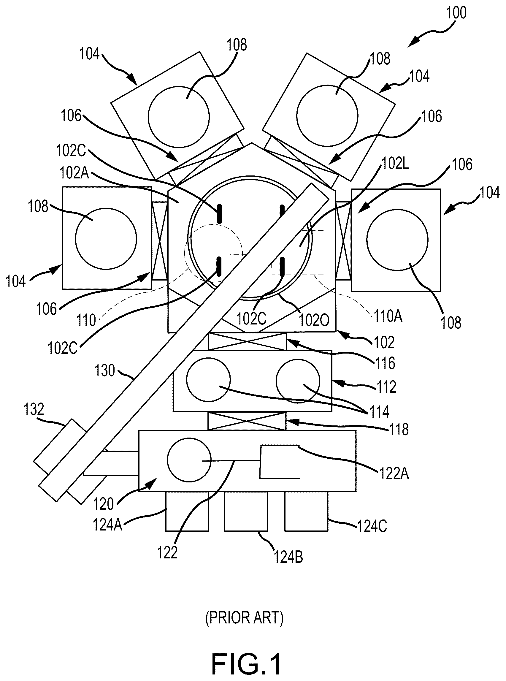
Existing substrate processing systems 100 include “cluster type” systems of the type generally shown in . Such substrate processing systems 100 include a substrate handling chamber 102 that operatively connects with two to four substrate processing chambers 104 via gate valves 106 . Each substrate processing chamber 104 is equipped to receive a substrate on a substrate support 108 that holds the substrate during processing (e.g., during material layer deposition as described above).
The substrate handling chamber 102 includes robotic arm 110 used to move substrates into and out of the various substrate processing chambers 104 through the gate valves 106 . In use, a gate valve 106 is opened, an end effector 110 A of the robotic arm 110 extends through the open gate valve 106 to insert a substrate into or remove a substrate from an interior chamber of the substrate processing chamber 104 (e.g., placing a substrate on or taking a substrate off the substrate support 108 ). Once the robotic arm 110 is retracted from the substrate processing chamber 104 , the gate valve 106 is closed, thereby sealing the substrate processing chamber 104 from the substrate handling chamber 102 . Then, other desired actions can take place in the substrate processing chamber 104 and/or the substrate handling chamber 102 .
further shows that this substrate processing system 100 includes a load-lock module 112 . The load-lock module 112 is connected with the substrate handling chamber 102 by gate valve 116 . The load-lock module 112 includes substrate holding components 114 for holding substrates on the way into the substrate handling chamber 102 for further processing and on the way out of the substrate handling chamber 102 (after processing is complete). The end effector 110 A of robotic arm 110 moves through the gate valve 116 (when opened) to move substrates from the load-lock module 112 into the substrate handling chamber 102 (for layer deposition and other processing) and from the substrate handling chamber 102 into the load-lock module 112 (after processing is completed). The load-lock module 112 and gate valve 116 keep the substrates isolated from the environment of the substrate handling chamber 102 until the conditions (e.g., temperature, pressure, content of atmosphere, etc.) within the substrate handling chamber 102 are ready for the substrate(s) to be inserted.
The load-lock module 112 further is coupled with an equipment front end module 120 via another gate valve 118 . The equipment front end module 120 includes a robotic arm 122 . The end effector 122 A of that robotic arm 122 moves through the gate valve 118 (when opened) to move substrates from the equipment front end module 120 into the load-lock module 112 (for layer deposition and/or other processing) and from the load-lock module 112 into the equipment front end module 120 (after processing is completed). The robotic arm 122 of the equipment front end module 120 also picks up new substrates for processing from one of the load ports 124 A- 124 C and returns processed substrates to one of the load ports 124 A- 124 C, e.g., to be transported to another location for further processing.
Substrate handling chambers 102 of this type typically include a chamber body 102 A (e.g., in which the robotic arm 110 is housed) having an access opening 1020 that is covered and sealed by a lid 102 L. The lid 102 L is removable to allow cleaning and other maintenance to the substrate handling chamber 102 , the robotic arm 110 , etc.
Removal of the lid 102 L of the substrate handling chamber 102 generally requires a hoisting mechanism due to size, weight, and/or shape of the lid 102 L. The lifting mechanism typically includes a gantry 130 that is built to span the lid 102 L of the substrate handling chamber 102 and a hoist 132 . The hoist 132 connects with the lid 102 L (e.g., at connectors 102 C) and exerts sufficient upward force to break the seal between the lid 102 L and the interior chamber of the substrate handling chamber 102 . The force required to break the seal can be significant, even after the substrate handling chamber 102 is vented. The gantry 130 enables the hoisted lid 102 L to be shifted away from the chamber body 102 A (by moving the hoist 132 and attached lid 102 L along gantry 130 to a location away from the remainder of the substrate processing system 100 ) to provide access to the interior of the substrate handling chamber 102 and the robotic arm 110 .
Conventional semiconductor production systems and methods of this type generally have been acceptable for their intended purpose, but there is room for improvement. Gantry-hoist arrangements of the types described above require space and may require periodic certification and inspection, thereby increasing cost of ownership and/or complicating service of the substrate processing system.
SUMMARY OF THE DISCLOSURE
Aspects of this technology relate to systems and methods for opening and closing interior chambers to enclosures (e.g., modules used in substrate processing systems, other chambers or containers, etc.). Some more particular aspects and examples of this technology relate to lid moving systems, enclosures (e.g., substrate handling chamber modules, substrate processing chamber modules, reactor chambers, storage containers, other containers, etc.) including such lid moving systems, and/or methods of moving a lid, e.g., to open and close access openings to such enclosures.
Lid moving systems and methods in accordance with examples of this technology facilitate reliable and safe movement of lids for chambers. Such systems may include one or more of: (a) a base member; (b) side walls extending from the base member with each including a cam surface defined therein; (c) a lid mounting arm extending away from the base member; (d) a first pivotal connection system engaging the cam surfaces and pivotally engaging the lid mounting arm; (e) a traveler member including a recess or opening on a surface facing the base member; (f) a second pivotal connection system pivotally engaging the traveler member with the lid mounting arm; (g) a motor for moving the traveler member (causing movement of the lid mounting arm with respect to the side walls); and/or (h) a stopper mechanism extending into the recess or opening of the traveler member from a direction of the surface facing the base member when the lid is opened.
Lid moving system in accordance with at least some examples of this technology may include one or more of: (a) a base member having a first side and a second side; (b) a first side wall extending from the first side of the base member, the first side wall including a first cam surface defined therein; (c) a second side wall extending from the second side of the base member, the second side wall including a second cam surface defined therein; (d) a lid mounting arm extending in a direction away from the base member; (e) a first pivotal connection system engaging the first cam surface and the second cam surface and pivotally engaging the lid mounting arm; (f) a traveler member including a recess or opening on a surface facing the base member; (h) a second pivotal connection system pivotally engaging the traveler member with the lid mounting arm; (i) a motor for moving the traveler member, wherein movement of the traveler member causes movement of the lid mounting arm with respect to the first side wall and the second side wall; and/or (j) a stopper mechanism configured to removably extend into the recess or opening of the traveler member from a direction of the surface facing the base member when the traveler member is at a lid open position.
In addition to one or more of the features described above, or as an alternative, the base member in lid moving systems in accordance with this technology may include a through hole aperture, wherein the stopper mechanism is removably engageable with the recess or opening of the traveler member through the through hole aperture of the base member when the traveler member is at the lid open position.
In addition to one or more of the features described above, or as an alternative, lid moving systems in accordance with this technology may include a heating element configured to heat at least a portion of the lid mounting arm.
In addition to one or more of the features described above, or as an alternative, in some examples of this technology, each of the first cam surface and the second cam surface may have a vertical cam segment at a first end and an angled cam segment extending upward and away from the vertical cam segment and away from the base member.
In addition to one or more of the features described above, or as an alternative, in some examples of this technology, each of the first side wall and the second side wall may include a tracking slot to define a direction of motion for the traveler member, wherein the traveler member includes one or more tracking elements extending into the tracking slots.
In addition to one or more of the features described above, or as an alternative, in some examples of this technology, the lid mounting arm may include a first end and a lid-engaging portion, wherein the first pivotal connection system is located at the first end and the second pivotal connection system is spaced from the first end toward the lid-engaging portion.
Additional aspects of this technology relate to enclosures. Such enclosures may include one or more of: (a) a main body member including a top, a bottom, and one or more sidewalls connecting the top and the bottom, wherein the top includes an opening providing access to an internal chamber defined in part by the main body member; (b) a lid sealingly attachable to the top of the main body member to close the internal chamber; and/or (c) a lid moving system engaged with the main body member, wherein the lid moving system includes one or more of: (i) a base member having a first side and a second side, wherein the base member includes a surface that faces in a direction away from the main body member, (ii) a first side wall extending from the first side of the base member, the first side wall including a first cam surface defined therein, (iii) a second side wall extending from the second side of the base member, the second side wall including a second cam surface defined therein, (iv) a lid mounting arm extending in a direction away from the base member, wherein the lid mounting arm is engaged with the lid at a first outer edge location of the lid, (v) a first pivotal connection system engaging the first cam surface and the second cam surface and pivotally engaging the lid mounting arm, (vi) a traveler member including a recess or opening on a surface facing the base member, (vii) a second pivotal connection system pivotally engaging the traveler member with the lid mounting arm, (viii) a motor for moving the traveler member, wherein movement of the traveler member causes movement of the lid mounting arm and the lid with respect to the main body member, and/or (ix) a stopper mechanism configured to extend into the recess or opening of the traveler member from a direction of the surface facing the base member when the traveler member is at a lid open position.
In addition to one or more of the features described above, or as an alternative, in some example enclosures in accordance with this technology, the base member may include a through hole aperture, and wherein the stopper mechanism is removably engageable with the recess or opening of the traveler member through the through hole aperture of the base member when the traveler member is at the lid open position.
In addition to one or more of the features described above, or as an alternative, some example enclosures in accordance with this technology may include a control system for controlling the motor, wherein the control system generates signals to stop operation of the motor when the lid is at the lid open position.
In addition to one or more of the features described above, or as an alternative, some example enclosures in accordance with this technology may include a heating element configured to heat at least one of (i) the lid at least at the first outer edge location or (ii) at least a portion of the lid mounting arm.
In addition to one or more of the features described above, or as an alternative, in some example enclosures in accordance with this technology, each of the first cam surface and the second cam surface may include a vertical cam segment at a first end and an angled cam segment extending upward and away from the vertical cam segment and away from the base member.
In addition to one or more of the features described above, or as an alternative, in some example enclosures in accordance with this technology, each of the first cam surface and the second cam surface may be configured such that, during a lid opening event: (i) the lid moving system initially lifts the lid upward at the first outer edge location until a seal between the lid and the main body member is unsealed and then (ii) the lid pivots upward away from the main body member about the first pivotal connection system and the second pivotal connection system.
In addition to one or more of the features described above, or as an alternative, in some example enclosures in accordance with this technology, each of the first side wall and the second side wall may include a tracking slot to define a direction of motion for the traveler member, wherein the traveler member includes one or more tracking elements extending into the tracking slots.
In addition to one or more of the features described above, or as an alternative, in some example enclosures in accordance with this technology, the lid mounting arm may include a first end and a lid-engaging portion, wherein the first pivotal connection system is located at the first end and the second pivotal connection system is spaced from the first end toward the lid-engaging portion.
In addition to one or more of the features described above, or as an alternative, in some example enclosures in accordance with this technology, the main body member may comprise a substrate handling chamber for moving substrates from the internal chamber to one or more substrate processing chambers.
Additional aspects of this technology relate to methods of moving a lid with respect to a main body member of an enclosure that include one or more of: (a) engaging a lid moving system with the lid, wherein the lid moving system includes: (i) a base member having a surface that faces in a direction away from the main body member, (ii) a lid mounting arm extending in a direction away from the base member, wherein the engaging includes engaging the lid mounting arm with the lid at a first outer edge location of the lid, (iii) a traveler member including a recess or opening on a surface facing the base member, (iv) a pivotal connection system pivotally engaging the traveler member with the lid mounting arm, and (v) a motor for moving the traveler member, wherein movement of the traveler member causes movement of the lid mounting arm and the lid; (b) operating the motor to initially apply a lifting force to the lid at the first outer edge location; (c) after the lifting force is applied, operating the motor to apply a rotational force to rotate the lid upward on the lid mounting arm in a direction away from the main body member to a lid open position; and (d) inserting a stopper mechanism into the recess or opening of the traveler member from a direction of the surface facing the base member to prevent the lid from moving from the lid open position.
In addition to one or more of the features described above, or as an alternative, in some example methods in accordance with this technology, the inserting may include inserting the stopper mechanism through a through hole opening provided in the base member and into the recess or opening of the traveler member.
In addition to one or more of the features described above, or as an alternative, in some example methods in accordance with this technology, the lifting force will break a sealed engagement between the lid and the main body member at the first outer edge location.
In addition to one or more of the features described above, or as an alternative, in some example methods in accordance with this technology, application of the lifting force to break the sealed engagement may include deforming a shape of the lid at the first outer edge location.
In addition to one or more of the features described above, or as an alternative, some example methods in accordance with this technology may include heating at least one of (i) the lid at least at the first outer edge location or (ii) at least a portion of the lid mounting arm prior to operating the motor to apply the lifting force.
In addition to one or more of the features described above, or as an alternative, in some example methods in accordance with this technology, the main body member may comprise a substrate handling chamber for moving substrates from the main body member to one or more substrate processing chambers.
In addition to one or more of the features described above, or as an alternative, some example methods in accordance with this technology may include a lid closing step.
In addition to one or more of the features described above, or as an alternative, some example methods in accordance with this technology may include, with the lid in the lid open position, one or more of: (i) removing the stopper mechanism from the recess or opening of the traveler member; and/or (ii) operating the motor to initially rotate the lid downward on the lid mounting arm in a direction toward the main body member and then move the lid downward to the main body member.
This summary is provided to introduce a selection of concepts relating to this technology in a simplified form. These concepts are described in further detail in the detailed description of examples of the disclosure below. This summary is not intended to identify key features or essential features of the claimed subject matter, nor is it intended to be used to limit the scope of the claimed subject matter.
BRIEF DESCRIPTION OF THE DRAWING FIGURES
These and other features, aspects, and advantages of the invention disclosed herein are described below with reference to the drawings of certain embodiments, which are intended to illustrate and not to limit the invention.
is a schematic view of a basic, prior art cluster type substrate processing system;
provides a schematic overhead view of an example substrate processing system in accordance with some examples of this technology;
A- 3 G provide various views illustrating features of a lid moving system incorporated with an enclosure (e.g., a substrate handling chamber) in accordance with some examples of this technology; and
A- 4 F ( 2 ) provide various views illustrating various features of lid moving operations in accordance with some examples of this technology.
It will be appreciated that elements in the figures are illustrated for simplicity and clarity and have not necessarily been drawn to scale. For example, the relative size of some of the elements in the figures may be exaggerated relative to other elements to help improve understanding of illustrated embodiments of the present disclosure.
DETAILED DESCRIPTION
Reference now will be made to the drawings wherein like reference numerals identify similar structural features or aspects of the subject disclosure.
illustrates an example substrate processing system 200 that includes lid moving systems 300 and/or uses lid moving methods in accordance with some examples of this technology. More specifically, schematically illustrates an overhead view of a substrate processing system 200 (e.g., a “cluster type” semiconductor processing system) having one or more “enclosures” that may include lid moving systems 300 and/or use lid moving methods in accordance with aspects of this technology. This specific example substrate processing system 200 includes a lid moving system 300 in accordance with examples of this technology engaged with substrate handling chamber 210 (which includes a main body 210 A, such as a main body member or chamber including a top, a bottom, one or more sidewalls connecting the top and the bottom, and a top access opening 2100 ). further illustrates lid moving system 300 in accordance with this technology connected with a lid 210 L covering access opening 2100 to an internal chamber of substrate handling chamber 210 in this “cluster type” substrate processing system 200 .
Substrate processing system 200 shown in includes: (a) substrate handling chamber 210 including a first robotic arm 212 having an end effector 212 A and the lid moving system 300 ; (b) load-lock module 220 connected at one edge or facet of substrate handling chamber 210 ; and (c) equipment front end module 230 that includes a second robotic arm 232 having an end effector 232 A connected with an opposite side of the load-lock module 220 from the substrate handling chamber 210 . The equipment front end module 230 may include or connect with a nitrogen gas source for providing a nitrogen gas atmosphere within the equipment front end module 230 . The equipment front end module 230 receives new substrates (e.g., wafers) for processing into the substrate processing system 200 and discharges processed substrates from the substrate processing system 200 via one or more loading ports 240 A- 240 D (moving the substrates between the loading port(s) 240 A- 240 D and the load-lock module 220 using second robotic arm 232 ). While four loading ports 240 A- 240 D are shown in the example of , more or fewer loading ports may be provided in other examples of this technology.
The substrate handling chamber 210 is connected with multiple substrate processing chambers 280 . Substrates are transferred into the substrate processing chambers 280 where one or more layers of material are deposited onto a surface of the substrate and/or other desired substrate processing takes place. shows each substrate processing chamber 280 including four substrate supports 282 onto which substrates can be placed during processing. More or fewer substrates supports 282 may be provided in each substrate processing chamber 280 (e.g., the substrate processing chambers 280 may be dual chamber modules (DCM) or quad chamber modules (QCM)). Substrate processing chambers 280 in accordance with some examples of this technology may include another four substrate supports 282 located vertically beneath the four substrate supports 282 shown in the top view of . Each of the substrate processing chambers 280 may have the same structures or one or more of the substrate processing chambers 280 may have a different structure from other substrate processing chambers 280 present.
The substrate handling chamber 210 is connected with its respective substrate processing chambers 280 via one or more gate valves 250 . While two gate valves 250 are shown connecting substrate handling chamber 210 with each of their respective substrate processing chambers 280 , more or fewer gate valves 250 may be provided with each substrate processing chamber 280 , in other examples of this technology. Substrate processing chambers 280 in accordance with some examples of this technology may be connected with substrate handling chamber 210 by another two gate valves 250 , e.g., located vertically beneath the two gate valves 250 shown in the top view of . When closed, the gate valves 250 sealingly separate the substrate handling chamber 210 from its connected substrate processing chambers 280 (so that independent atmospheric conditions may be maintained in each chamber). When open, the gate valves 250 provide an opening (e.g., a substrate transfer slot) through which the end effector 212 A of first robotic arm 212 can extend to move substrates into and out of the substrate processing chamber 280 . The openings through the gate valves 250 align with substrate transfer slots provided in the substrate processing chambers 280 and the substrate handling chamber 210 to enable substrates to be moved between the substrate processing chambers 280 and the substrate handling chamber 210 through the gate valves 250 . Each of gate valves 250 may have the same structures or one or more of the gate valves 250 may have a different structure from other gate valves 250 present.
One face of the load-lock module 220 connects with the equipment front end module 230 by one or more gate valves 260 A (two shown in ), and the opposite face of the load-lock module 220 connects with the substrate handling chamber 210 by one or more gate valves 260 B. The load-lock module 220 further includes one or more substrate supports 222 (two shown in ) for holding substrates while they wait to be moved into the equipment front end module 230 or the substrate handling chamber 210 . When closed, the gate valves 260 A, 260 B sealingly separate the load-lock module 220 from the equipment front end module 230 and the substrate handling chamber 210 (so that independent atmospheric conditions may be maintained in each chamber). When open, the gate valves 260 A provide an opening (e.g., a substrate transfer slot) through which the end effector 232 A of second robotic arm 232 can extend to move substrates into and out of the equipment front end module 230 . The openings through the gate valves 260 A align with substrate transfer slots provided in the equipment front end module 230 and the load-lock module 220 to enable substrates to be moved between the equipment front end module 230 and the load-lock module 220 through gate valves 260 A. When open, the gate valves 260 B provide an opening (e.g., a substrate transfer slot) through which the end effector 212 A of first robotic arm 212 can extend to move substrates into and out of the substrate handling chamber 210 . The openings through the gate valves 260 B align with substrate transfer slots provided in the substrate handling chamber 210 and the load-lock module 220 to enable substrates to be moved between the substrate handling chamber 210 and the load-lock module 220 through gate valves 260 B. Each of gate valves 260 A, 260 B may have the same structure or one or more of the gate valves 260 A, 260 B may have a different structure from other gate valves 260 A, 260 B present.
As noted above, the substrate handling chamber 210 of this example is equipped with a lid moving system 300 in accordance with aspects of this technology. This example lid moving system 300 will be discussed in more detail below in conjunction with A- 3 G . A provides a perspective view of the load-lock module 220 and substrate handling chamber 210 (including lid moving system 300 ) of substrate processing system 200 with the substrate processing chambers 280 and equipment front end module 230 removed. B provides a perspective view of a lid moving system 300 with attached lid 210 L in accordance with some examples of this technology. C and 3 D show a side view and a sectional view, respectively, of portions of the lid moving system 300 in a “lid open” position in accordance with examples of this technology. E provides additional details regarding cam surfaces in accordance with some examples of this technology. F provides a face-on view of a portion of a “tower” of the lid moving system 300 . G provides an exploded view of the lid moving system 300 in accordance with some examples of this technology to illustrate its various parts. Where the same reference number is used in A- 3 G as used in (or other figures), the same or similar parts are being referenced, and much of the overlapping description may be omitted.
As shown in A , lid 210 L covers and seals an opening to an interior chamber 210 C that contains first robotic arm 212 (first robotic arm 212 is not visible in the view of A ). The lid 210 L and/or the rim (lid seat) of the opening may include a seal component (e.g., a gasket, an elastomeric O-ring, etc.) to help maintain a sealed environment within the interior chamber 210 C (e.g., so that the interior chamber 210 C may be maintained under vacuum and/or under different atmospheric conditions from substrate processing chambers 280 and/or the load-lock module 220 ). The lid 210 L of this example further includes additional securing devices 214 that secure to the main body 210 A (e.g., through bolted connections) to provide further securing of the lid 210 L to the main body 210 A. In this illustrated example, the additional securing devices 214 are spaced around the perimeter 210 P of the lid 210 L. While not a requirement in all examples of this technology, lid 210 L of this illustrated example further includes some sealed viewing windows 210 W providing visual access to the interior chamber 210 C through the top.
Additional features of the lid moving system 300 and its engagement with lid 210 L now will be described in more detail in conjunction with A- 3 G . This example lid moving system 300 includes a base member 302 (e.g., a rear panel) having a first side 302 A (e.g., a right side of center when looking at a major surface 302 S of the base member 302 —see F ) and a second side 302 B (e.g., a left side of center when looking at the major surface 302 S of the base member 302 —see F ). A first side wall 304 A extends from the first side 302 A of the base member 302 (e.g., in a direction toward lid 210 L and/or toward lid mounting arm 310 and/or in a direction away from major surface 302 S). This first side wall 304 A includes a first cam surface 306 A defined therein. Similarly, the lid moving system 300 further includes a second side wall 304 B extending from the second side 302 B of the base member 302 (e.g., in a direction toward lid 210 L and/or toward lid mounting arm 310 and/or in a direction away from major surface 302 S), and this second side wall 304 B also includes a second cam surface 306 B defined therein. Base member 302 , first side wall 304 A, and second side wall 304 B of this example are fixedly mounted with respect to (e.g., by a bolted connection) the main body 210 A of the substrate handling chamber 210 (e.g., at a location opposite the location of the load-lock module 220 ). The base member 302 , first side wall 304 A, and second side wall 304 B (optionally together with a top member 304 T and/or bottom member 304 X) may form a “tower” like structure of the lid moving system 300 . The parts forming the “tower” structure may define an interior chamber 304 V, e.g., with an open front face, as shown in B . In this illustrated example, the substrate handling chamber 210 has a generally regular pentagonal shape (or at least its gate valve mounting locations are arranged in a pentagonal shape), the load-lock module 220 is coupled to one facet of the pentagonal shape, and the lid moving system 300 (e.g., at least base member 302 , first side wall 304 A, and second side wall 304 B (or the “tower”) thereof) is located at a corner of the pentagonal shape directly across the substrate handling chamber 210 from the load-lock module 220 . The lid moving system 300 , however, could be located at other positions around the substrate handling chamber 210 , if desired (e.g., at other corners of the pentagonal shape and/or to enclosures of other shapes).
Lid mounting arm 310 extends in a direction away from the base member 302 (and toward the lid 210 L). The lid mounting arm 310 of this illustrated example includes a first arm member 310 A at one side and a second arm member 310 B at the other side. As shown in B , a base member 318 P (e.g., a base plate) extends between the arm members 310 A, 310 B, and the base member 318 P, the first arm member 310 A, and/or the second arm member 310 B engage a top surface of the lid 210 L near a perimeter 210 P of the lid 210 L, e.g., by bolts. Thus, the lid mounting arm 310 is fixed to the lid 210 L (e.g., in a cantilevered arrangement), but the mounting arm 310 is movable with respect to base member 302 , first side wall 304 A, and second side wall 304 B (and with respect to the overall “tower”).
As shown in C 3 D, and 3 G, a first pivotal connection system 320 engages the first cam surface 306 A of the first side wall 304 A and the second cam surface 306 B of the second side wall 304 B. The first pivotal connection system 320 of this example includes one or more axles 320 A, 320 B (e.g., pins) mounted to or integrally formed with the lid mounting arm 310 , e.g., at a coupling 322 A, 322 B, respectively (e.g., a part forming a mounting hole for an axle). The axle(s) 320 A, 320 B may be fixed with respect to the lid mounting arm 310 (e.g., fixed with respect to first arm member 310 A and second arm member 310 B, respectively). The axle(s) 320 A, 320 B extend into and engage cam surfaces 306 A and/or 306 B in a manner such that the axle(s) 320 A, 320 B can slide and rotate within their respective cam surface 306 A, 306 B. Any type of connection may be used in accordance with this technology. For example, the first arm member 310 A may include a coupling 322 A that is separate part from the coupling 322 B provided on the second arm member 310 B, or a single coupling part may be provided (e.g., extending between arm members 310 A, 310 B). As another example, axle 320 A may be a separate part from axle 320 B, or axles 320 A and 320 B may constitute opposite ends of a single axle member. As another example, the axle(s) 320 A, 320 B may constitute one or more rods that are fixed to or integrally formed at the first end 316 of the first arm member 310 A and second arm member 310 B and are sized and shaped to permit rotation within cam surfaces 306 A, 306 B. Alternatively, in some examples, axle(s) 320 A, 320 B may rotate with respect to coupling(s) 322 A, 322 B, respectively. In the specific example shown in G , the axles 320 A, 320 B extend through couplings 322 A, 322 B, respectively, and into opposite ends of a mount member 316 M provided at the first end 316 of the first arm member 310 A and second arm member 310 B. Mount member 316 M in this example includes one or more holes that receive ends of the axle(s) 320 A and 320 B.
As noted above, the axle(s) 320 A and 320 B engage cam surfaces 306 A and 306 B, respectively. The cam surfaces 306 A and 306 B guide movement of the lid mounting arm 310 and the engaged lid 210 L when the lid 210 L is moved, as will be described in more detail below. As shown in E along with C and 3 D , in this illustrated example, each of the first cam surface 306 A and the second cam surface 306 B has a vertical cam segment 306 V at a first end thereof and an angled cam segment 306 X extending upward and away from the vertical cam segment 306 V (and away from the base member 302 ) to a second end of cam surface 306 A, 306 B. The “vertical” and “upward” orientations are present when this example lid moving system 300 is mounted on a substrate handling chamber 210 for typical use, e.g., in the manner illustrated in A . Thus, the angled cam segments 306 X (and the movement of axle(s) 320 A, 320 B induced by them) include both vertical and horizontal components when the lid moving system 300 is mounted on a substrate handling chamber 210 . The vertical cam segment 306 V and the angled cam segment 306 X define an angle A, as shown in E . Angle A may be an obtuse angle, e.g., within a range of 95 degrees to 150 degrees, and in some examples, within a range of 100 degrees and 140 degrees or within a range of 105 degrees and 130 degrees. In the illustrated example, Angle A is about 120 degrees.
C, 3 D, and 3 G further show that this example lid moving system 300 includes a traveler member 330 used to move the lid mounting arm 310 (and the lid 210 L attached to it). Traveler member 330 of this example includes a base element 330 A. A recess 330 R (or opening) is defined in (or through) the base element 330 A (or other part of the traveler member 330 ), e.g., on a surface 332 of the traveler member 330 that directly faces the base member 302 . See D . The opening to this recess 330 R may be provided at a location on surface 332 offset from a central vertical axis or location of the traveler member 330 (and/or offset from a central vertical axis or location of the base member 302 or “tower”). Further, the base member 302 of this example includes an opening 3020 (e.g., a through hole aperture) that overlaps with (e.g., at least partially aligns in an axial or length direction) with the recess 330 R defined in (or through) the base element 330 A of traveler member 330 when the traveler member 330 is in a lid open position. As shown in F , the opening 3020 (and recess 330 R of traveler member 330 ) may be offset to one side of the base member 302 (e.g., located within the first side 302 A, in this illustrated example). The offset (from center) position of opening 3020 and recess 330 R provides additional room for incorporating those features into the lid moving system 300 structures (e.g., offset from a central track or other components on which the traveler 330 moves) and allows easy access to the opening 3020 for inserting a stopper mechanism 360 (described in more detail below).
Traveler member 330 of this example further includes one or more tracking elements 334 , e.g., extending outward from each side of the base element 330 A. Two tracking elements 334 are shown on each side of traveler member 330 in the example of C, 3 D, and 3 G . The tracking elements 334 fit into and engage corresponding tracking slots 304 C and 304 D defined in first side wall 304 A and second side wall 304 B, respectively. The tracking slots 304 C and 304 D and the tracking element(s) 334 extending into (and engaged with) them define a direction of motion of the traveler member 330 when motor 350 moves the traveler member 330 (which in turn, moves the lid mounting arm 310 and the connected lid 210 L). The traveler member 330 moves in a vertical direction in this illustrated example (although other orientations are possible). The traveler member 330 may be mounted on a lead screw that rotates (e.g., driven by motor 350 and gear box, driven by a hand crank, etc.) to move the traveler member 330 up and down (with the direction of motion of the traveler member 330 controlled by the tracking elements 334 , the tracking slots 304 C and 304 D, the side walls 304 A and 304 B, and/or the screw drive).
A second pivotal connection system 340 pivotally engages the traveler member 330 with the lid mounting arm 310 . The second pivotal connection system 340 of this example includes one or more axles 340 A (or pins) that is/are pivotally (rotatably) mounted to a coupling 340 B provided or engaged with the traveler member 330 (e.g., with the axle(s) 340 A extending through a portion of traveler member 330 defining an axle mounting hole 330 H, shown in G ). The axle(s) 340 A are fixed with respect to the lid mounting arm 310 , and optionally integrally formed as part of the lid mounting arm 310 (e.g., with one axle 340 A fixed to first arm member 310 A and another axle 340 A fixed to second arm member 310 B). Alternatively, the axle(s) 340 A could be fixed with the traveler member 330 at coupling(s) 340 B but rotatable within an axle mounting opening(s) or coupling(s) provided with the lid mounting arm 310 .
Any type of connection at the second pivotal connection system 340 may be used in accordance with this technology. For example, the first arm member 310 A may include an axle support that is separate part from an axle support provided on the second arm member 310 B, or a single axle support may be provided (e.g., extending between arm members 310 A, 310 B). As another example, a single axle 340 A may be provided that engages (or is integrally formed with) both first arm member 310 A and second arm member 310 B, or separate axle 340 A parts may be provided (with one axle 340 A provided with first arm member 310 A and a separate axle 340 A provided with second arm member 310 B). The axle(s) 340 A and the opening of the coupling(s) 340 B may be sized and shaped to permit rotation of the arm members 310 A, 310 B with respect to the traveler 330 about axle(s) 340 A within the opening of the coupling(s) 340 B. If necessary or desired, a bearing or other rotation supporting structures may be provided at the rotational engagement location between the axle(s) 340 A and the coupling(s) 340 B.
Additional details of the specifically illustrated example second pivotal connection system 340 will be described with additional reference to G . As shown, the axle mounting hole 330 H of the traveler member 330 is provided at a rotational or pivotal mount area 330 P of the traveler member 330 . The rotational or pivotal mount area 330 P is located opposite and somewhat below surface 332 in this illustrated example, and/or it extends outward and below base element 330 A of the traveler member 330 . In this illustrated example, as evident from G , the rotational or pivotal mount area 330 P extends into a recess or opening 310 R defined in a top surface of the lid mounting arm 310 such that axle mounting hole 330 H of the traveler member 330 axially aligns with axle holes 310 H provided in the lid mounting arm 310 (e.g., with one axle hole 310 H provided in first arm member 310 A and another axle hole 310 H provided in second arm member 310 B in this illustrated example). The axle holes 310 H open into recess 310 R. Axle 340 A extends through axle holes 310 H of the lid mounting arm 310 and through axle mounting hole 330 H of the traveler member 330 to rotatably mount the lid mounting arm 310 with respect to the traveler member 330 . Thus, the axle 340 A extends through axle holes 310 H and through recess 310 R (with the axle 340 A located inside of axle mounting hole 330 H of the traveler member 330 in the recess 310 R).
As shown in the example of D and 3 G , the lid mounting arm 310 (e.g., each of first arm member 310 A and second arm member 310 B) includes or extends to a first end 316 that includes the first pivotal connection system 320 . Also, the lid mounting arm 310 (e.g., each of first arm member 310 A and second arm member 310 B) includes a lid-engaging portion 318 where the lid mounting arm 310 is coupled to the lid 210 L (e.g., by bolted connections). In this illustrated example, the second pivotal connection system 340 is spaced from the first end 316 toward the lid-engaging portion 318 . In this manner, the lid-engaging portion 318 is located closer to the second pivotal connection system 340 than to the first pivotal connection system 320 . The second pivotal connection system 340 may be located at or within the lid-engaging portion 318 in some examples of this technology. As shown in B , the lid-engaging portion 318 of this example includes a base member 318 P (e.g., a base plate) extending between the arm members 310 A, 310 B, and one or more of the base member 318 P, the first arm member 310 A, and/or the second arm member 310 B engages a top surface of the lid 210 L, e.g., by bolts.
This example lid moving system 300 further includes a motor 350 for moving the traveler member 330 . The motor 350 may move a shaft 352 or other support member that is engaged with the traveler member 330 . Movement of the traveler member 330 causes movement of the lid mounting arm 310 with respect to the first side wall 304 A and the second side wall 304 B (or “tower” structure), as will be discussed in more detail below.
The lid moving system 300 of this example further includes a stopper mechanism 360 to hold the lid 210 L in the open position. The stopper mechanism 360 of this illustrated example includes a rod 362 configured to: (i) extend through the opening 3020 (e.g., a through hole aperture) defined through the base member 302 and (ii) removably extend into (or through) the recess 330 R (or opening) of the traveler member 330 . The stopper mechanism 360 extends into opening 330 R from a direction of the surface 332 of the traveler member 330 that faces the base member 302 when the traveler member 330 is at a lid open position, as shown in C and 3 D (and as will be discussed in more detail below). As evident from D , the stopper mechanism 360 extends to contact base member 302 and traveler 330 and prevents the traveler 330 from moving up and down with respect to base member 302 .
As shown schematically in B , lid moving systems 300 in accordance with at least some examples of this technology may include one or more heating elements 370 . The heating element(s) 370 , when present, may be used to heat up the junction between the lid 210 L and the lid mounting seat provided on the main body 210 A of the substrate handling chamber 210 . The heating element(s) 370 can heat the lid 210 L and main body 210 A to help break the seal between these components as the lid 210 L is being lifted (as will be described in more detail below). The heating element(s) 370 may be provided: (i) as part of the lid moving system 300 (e.g., on one or more of the lid mounting arm 310 , first arm member 310 A, second arm member 310 B, base member 318 P, first side wall 304 A, second side wall 304 B, base member 302 , or base “tower”); (ii) as part of the lid 210 L (e.g., on or at a periphery of the lid 210 L); and/or (iii) on the main body 210 A of the substrate handling chamber 210 . Example heating element 370 locations are shown schematically in A and 3 B .
Operation of the lid moving system 300 to move a lid 210 L now will be described in more detail with additional reference to A- 4 F ( 2 ). A- 4 C ( 2 ) illustrate features of an initial lid lifting phase of a lid moving operation in which the lid moving system 300 initially lifts the lid 210 L upward (at least at one outer edge location) until any residual seal between the lid 210 L and the main body 210 A is unsealed. D- 4 F ( 2 ) illustrate features of a lid rotational phase of the lid moving operation in which the lid moving system 300 pivots the lid 210 L upward and away from the main body 210 A about the first pivotal connection system 320 and the second pivotal connection system 340 . B ( 1 ), 4 C( 1 ), 4 E( 1 ), and 4 F( 1 ) only show representations of the cam surfaces 306 A, 306 B; the axle(s) 320 A, 320 B engaging the cam surfaces 306 A, 306 B; tracking slots 304 C, 304 D; and the tracking elements 334 engaging the tracking slots 304 C, 304 D. B ( 2 ), 4 C( 2 ), 4 E( 2 ), and 4 F( 2 ) show more complete views of the lid moving system 300 , its motion, and motion of the lid 210 L at the pivotal locations shown in B ( 1 ), 4 C( 1 ), 4 E( 1 ), and 4 F( 1 ), respectively.
To start, as illustrated in , 3 A, 4 A, and 4 D , a lid moving system 300 is engaged with the lid 210 L, e.g., by bolting (or otherwise connecting) the lid 210 L with the lid mounting arm 310 of the lid moving system 300 (e.g., at a base member 318 P and/or arm members 310 A, 310 B). This engagement step may be completed during initial manufacture of the substrate handling chamber 210 or, in some examples, the lid moving system 300 may be engaged with a substrate handling chamber 210 and/or lid 210 L as an “after market” product or option. The lid moving system 300 may have a structure like that described above, e.g., including:
•
• a) a base member 302 having a major surface 302 S that faces in a direction away from the main body 210 A of the substrate handling chamber 210 (e.g., the lid moving system 300 potentially having a “tower” structure of the types described above (at least including base member 302 , first side wall 304 A, and second side wall 304 B)); • b) a lid mounting arm 310 (e.g., including first arm member 310 A and second arm member 310 B) extending in a direction away from the base member 302 —the lid mounting arm 310 (and its arm members 310 A, 310 B) may be engaged with the lid 210 L at a first outer edge location 310 P of the lid 210 L, e.g., via base member 318 P; • c) a traveler member 330 including a recess 330 R or opening on a surface 332 facing the base member 302 ; • d) a pivotal connection system 340 pivotally engaging the traveler member 330 with the lid mounting arm 310 ; and • e) a motor 350 operatively coupled for moving the traveler member 330 .
The lid mounting arm 310 further may be connected by a first pivotal connection system 320 to side walls 304 A and 304 B extending from the base member 302 and away from its major surface 302 S. As will be described in more detail below, movement of the traveler member 330 with respect to the base member 302 causes movement of the lid mounting arm 310 and the lid 210 L.
At the start of a lid moving operation, the lid 210 L may be sealed to the main body 210 A of the substrate handling chamber 210 , as shown in A . The substrate handling chamber 210 may be under a vacuum or low pressure condition and/or other atmospheric conditions that differ from the exterior atmospheric conditions. With the lid 210 L in the sealed position shown in A : (i) the axles 320 A, 320 B located at the first end 316 of the mounting arm 310 are positioned at the bottom of the vertical cam segment 306 V of cam surfaces 306 A, 306 B, respectively; and (ii) the tracking elements 334 of the traveler member 330 are positioned toward the bottom of the tracking slots 304 C, 304 D. See B ( 1 ) and 4 B( 2 ).
As an initial step, if present (and needed), any fastening elements securing the lid 210 L to the main body 210 A of the substrate handling chamber 210 (such as the additional securing devices 214 ) will be disengaged (so that the lid 210 L is no longer fastened to the main body 210 A). This step may result in an initial “venting” of the interior chamber 210 C (e.g., making the pressure within the interior chamber 210 C equal to (or substantially equal to) the exterior environmental pressure conditions). Additionally or alternatively, if needed, a separate “venting” step may be performed (e.g., before additional securing devices 214 are removed) to make the pressure within the interior chamber 210 C equal to (or substantially equal to) the exterior environmental pressure conditions.
In some instances, the above described “venting” step(s) alone may not be sufficient to completely unseal the junction between the lid 210 L (e.g., its perimeter rim) and the lid-engaging structures (e.g., lid seal seat) provided on the main body 210 A of the substrate handling chamber 210 . For this reason, lid moving systems 300 and lid moving methods according to at least some aspects of this technology include an initial lid lifting phase in the lid moving operation. In the initial lid lifting phase, the lid moving system 300 initially applies force to lift the lid 210 L upward at least at the first outer edge location 310 P (which is a location adjacent a place where the lid 210 L is engaged with the lid mounting arm 310 ). See arrow U in A . This initial lid lifting action near the mounting arm 310 pulls the edge of the lid 210 L upward at least near the mounting arm 310 to break any residual seal between the lid 210 L and the main body 210 A. More specifically, in the illustrated example, the motor 350 turns a screw drive on which the traveler member 330 is mounted. This action moves the traveler member 330 upward, which in turn: (a) moves tracking elements 334 upward in tracking slots 304 C, 304 D and (b) moves axles 320 A and 320 B upward in the vertical cam segment 306 V of the cam surfaces 306 A, 306 B. Compare B ( 1 ) and 4 B( 2 ) with C ( 1 ) and 4 C( 2 ) ( C ( 2 ) shows a small gap G between the bottom of lid 210 L and the top surface of the main body 210 A of substrate handling chamber 210 , whereas B ( 2 ) shows an abutting relationship between these parts). The unsealing action may be accompanied with an audible “pop,” “hiss,” or other sound as the seal is broken and the pressures inside and outside the substrate handling chamber 210 equalize and/or as parts that are stuck together become unstuck (e.g., as the lid 210 L lifts from a seal or from the lid seat provided around opening 2100 ). In some instances, the residual sealing and/or sticking force and the force applied to the lid 210 L by the motor 350 lifting the lid mounting arm 310 may be sufficient to somewhat deform (e.g., temporarily bend) the lid 210 L, e.g., near the first outer edge location 310 P and/or at locations proximate to the attachment of the first arm member 310 A, the second arm member 310 B, and/or base member 318 P to the lid 210 L. This deformation, when it occurs, can help break the seal and/or stickiness at or near the first outer edge location 310 P and help complete the venting and unsealing processes.
Additionally or alternatively, in at least some examples of this technology, during or prior to the initial “venting” action and/or the initial lid lifting phase, heat (e.g., via heating element(s) 370 ) may be applied to one or more of: (a) the lid 210 L (e.g., at least at or near the first outer edge location 310 P); (b) at least a portion of the lid mounting arm 310 (e.g., one or more of first arm member 310 A, second arm member 310 B, and/or base member 318 P); and/or (c) the main body 210 A of the substrate handling chamber 210 (e.g., at least at or near the first outer edge location 310 P). Such heating may take place prior to and/or while operating the motor 350 to apply the lifting force during the initial lid lifting phase described above.
After the initial lid lifting phase is completed, the motor 350 may continue to move the traveler member 330 upward to apply a rotational force to pivot the lid 210 L upward. See arrow R in D . This force rotates the lid 210 L on the lid mounting arm 310 in a direction upward and away from the main body 210 A of the substrate handling chamber 210 to a “lid open position” (e.g., as shown in C and 3 D ). Starting with the axles 320 A, 320 B and tracking elements 334 at the locations shown in C ( 1 ) and 4 C( 2 ), during this lid rotation phase, the motor 350 continues to move the traveler member 330 upward (e.g., by rotating screw drive). This action: (a) moves tracking elements 334 upward in tracking slots 304 C, 304 D and (b) moves axles 320 A and 320 B upward and in an angled direction within the angled cam segment 306 X of the cam surfaces 306 A, 306 B. Compare C ( 1 ) and 4 C( 2 ) with E ( 1 ) and 4 E( 2 ). Because of the pivotal connection system(s) 320 and/or 340 , this action also begins to rotate the lid mounting arm 310 and the lid 210 L connected to it upward and away from the top surface of the main body 210 A of the substrate handling chamber 210 .
Continued operation of the motor 350 continues the movement of tracking elements 334 upward in tracking slots 304 C, 304 D and movement of axles 320 A and 320 B upward and in an angled direction within the angled cam segment 306 X of the cam surfaces 306 A, 306 B until the lid 210 L reaches a lid open position. Compare E ( 1 ) and 4 E( 2 ) with F ( 1 ) and 4 F( 2 ). One or more sensors may be provided (e.g., limit switches) to generate signals when the lid 210 L has reached the lid open position and/or the lid closed position (e.g., upper and lower limit switches). Signals from such sensors may allow an automated control system to automatically stop operation of the motor 350 when the upper limit of rotation (opening the lid 210 L) has been reached and/or when the lower limit of rotation (closing the lid) has been reached. The sensor(s) may sense one or more of: location of the traveler member 330 ; location of tracking elements 334 ; location of the lid 210 L; location of the lid mounting arm 310 ; location of the first arm member 310 A and/or second arm member 310 B; location of axle(s) 320 A, 320 B; contact between a lid 210 L part and a main body 210 A part; etc. Such sensors and their use for automated motor control (e.g., shut off) are known and commercially available.
C and 3 F schematically illustrate a control panel 390 fixed to the base member 302 , operatively coupled to the motor 350 and automated control system, and used to operate the motor 350 . In the illustrated arrangement, the control panel 390 is accessible from the rear of the substrate handling chamber 210 , optionally from the ground floor (e.g., without the operator having to be on top of the substrate handling chamber 210 and/or on a ladder). The control panel 390 may allow an operator to initiate a “lid opening” process (e.g., via button 390 A, see F ), a “lid closing” process (e.g., via button 390 B), an “emergency stop” process (e.g., via button 390 C), and/or other desired functions. The automated control system may include/run software for operation of the lid moving system 300 , e.g., initiating lid opening processes; initiating lid closing processes; requiring reversal of the motor 350 when either of the upper and lower limit switches is tripped; recognizing overcurrent states in the event that the motor 350 is actuated when the stopper mechanism 360 is in place; etc. The control panel 390 may include physical buttons or switches, soft buttons or switches, a touch screen, and/or any desired types of controllers or input devices (e.g., a keyboard, a mouse or other pointer devices, etc.).
Once in the lid open position, e.g., the position shown in C, 3 D, 4 F ( 1 ), and 4 F( 2 ), the stopper mechanism 360 (e.g., a hardened steel rod 362 ) may be inserted into the recess 330 R of the traveler member 330 . In at least some examples of this technology, the stopper mechanism 360 can be inserted into the recess 330 R from the direction of the surface 332 of the traveler member 330 that faces the base member 302 . The stopper mechanism 360 may be inserted through an opening 3020 (e.g., a through hole aperture) formed in the base member 302 and then into recess 330 R. The illustrated structures and arrangement enable an operator to insert the rod 362 into the opening 3020 and/or recess 330 R from a location behind the substrate handling chamber 210 (e.g., the operator need not be on top of the substrate handling chamber 210 and/or on a ladder to insert the stopper mechanism 360 ). The stopper mechanism 360 forms a releasable and fixed connection between the traveler member 330 and the base member 302 to prevent the traveler member 330 from moving vertically and thus preventing the lid 210 L from moving downward from the lid open position. This feature helps assure the lid 210 L remains in the open position, e.g., while technicians or others interact with equipment inside the interior chamber 210 C of the substrate handling chamber 210 through its top access opening 2100 .
To close the lid 210 L, the processes described above are reversed. If necessary, the stopper mechanism 360 (e.g., rod 362 ) is removed from the recess 330 R of the traveler member 330 (and optionally pulled out of the opening 3020 of the base member 302 ). If necessary, the motor 350 may be operated to slightly lift the traveler member 330 (to relieve any pinching or binding force on the stopper mechanism 360 so it can be removed more easily). The motor 350 then is operated to move the traveler member 330 downward. During this phase, operation of the motor 350 moves tracking elements 334 downward in tracking slots 304 C, 304 D and moves axles 320 A and 320 B downward and in an angled direction within the angled cam segment 306 X of the cam surfaces 306 A, 306 B. Compare F ( 1 ) and 4 F( 2 ) with E ( 1 ) and 4 E( 2 ). These actions begin to rotate the lid 210 L downward on the lid mounting arm 310 in a direction toward the main body 210 A.
Continued operation of the motor 350 to close the lid 210 L further moves tracking elements 334 downward in tracking slots 304 C, 304 D and moves axles 320 A and 320 B downward and in an angled direction within the angled cam segment 306 X of the cam surfaces 306 A, 306 B until the axles 320 A, 320 B reach the end of the angled cam segment 306 X. Compare E ( 1 ) and 4 E( 2 ) with C ( 1 ), and 4 C( 2 ). These actions are accompanied with continued downward rotation of the lid 210 L. Then, continued operation of the motor 350 to close the lid 210 L further moves tracking elements 334 downward in tracking slots 304 C, 304 D and moves axles 320 A and 320 B downward within the vertical cam segment 306 V of the cam surfaces 306 A, 306 B, e.g., until the axles 320 A, 320 B reach the bottom of the vertical cam segment 306 V. Compare C ( 1 ) and 4 C( 2 ) with B ( 1 ) and 4 B( 2 ). This action may trigger sensors of the lower limit switch(es) to automatically stop operation of the motor 350 . At this point, the lid 210 L is correctly positioned over the access opening 2100 of the main body 210 A of the substrate handling chamber 210 . If necessary, other lid securing action(s) may be taken (e.g., securing additional securing devices 214 ), and the substrate handling chamber 210 may be sealed and ready to accommodate a vacuum or other atmospheric environment.
While described above in terms of lid moving systems 300 for substrate handling chambers 210 of cluster type substrate processing systems 200 , lid moving systems 300 of the types described herein may be used with removable lids provided with other types of enclosures, such as substrate processing chambers 280 ; chemical reaction vessels; storage tanks; other containers; etc.
Also, while the above examples utilize a computer-controlled motor 350 to move traveler member 330 upward and downward with respect to side walls 304 A, 304 B, in some examples of this technology, the motor 350 need not be computer-controlled (e.g., it could be manually controlled) or could be replaced by a hand-operated crank mechanism (e.g., used to turn a screw drive to move the traveler member 330 upward and downward).
Some advantageous features or results that may be realized in at least some examples of this technology include: (a) providing access to the inner faces of the substrate processing 280 modules and/or the load-lock module 220 from above or from within the substrate handling chamber 210 ; (b) providing lid moving systems 300 with a small footprint, e.g., for use with smaller sized chambers or containers; (c) providing automated systems and methods to better “vent” or unseal a lid 210 L before beginning rotation of the lid 210 L; (d) limiting movement of the traveler 330 , e.g., within a predetermined region defined by the side walls 304 A and 304 B (e.g., within an interior chamber 304 V of a “tower” structure); (e) preventing undesired or unplanned movement of the lid 210 L from the lid open position (e.g., due to accidental activation, mechanical failure, etc.); (f) enabling remote operation of the lid moving system 300 , e.g., from a ground-based position behind the substrate handling chamber 210 ; (g) avoiding the need to build a gantry and/or other structure over the substrate handling chamber 210 when lid removal is needed; (h) maintaining the lid 210 L securely attached to the lid moving system 300 in a stowed (lid open) position without the need to completely remove the lid 210 L from the area of the substrate handling chamber 210 ; and/or (i) reducing the size of the equipment and/or force needed to move the lid 210 L using the initial lid lifting phase (e.g., for venting and/or unsealing) followed by the lid pivot phase, and or using localized heating prior to or during the initial lid lifting phase.
Although this disclosure has been provided in the context of certain embodiments and examples, it will be understood by those skilled in the art that the disclosure extends beyond the specifically described embodiments to other alternative embodiments and/or uses of the embodiments and obvious modifications and equivalents thereof. In addition, while several variations of the embodiments of the disclosure have been shown and described in detail, other modifications, which are within the scope of this disclosure, will be readily apparent to those of skill in the art based upon this disclosure. It is also contemplated that various combinations or sub-combinations of the specific features and aspects of the embodiments may be made and still fall within the scope of the disclosure. It should be understood that various features and aspects of the disclosed embodiments can be combined with, or substituted for, one another in order to form varying modes of the embodiments of the disclosure. Thus, it is intended that the scope of the disclosure should not be limited by the particular embodiments described above.
The headings provided herein, if any, are for convenience only and do not necessarily affect the scope or meaning of the devices and methods disclosed herein.
Figures (13)
Citations
This patent cites (56)
- US3961723
- US4566730
- US4587760
- US4923246
- US4982995
- US5503450
- US6019417
- US6168224
- US6308650
- US6428091
- US6520558
- US6547319
- US6558506
- US6623062
- US6814392
- US6830281
- US6834463
- US7059669
- US7083217
- US7425033
- US7451888
- US7578406
- US7703623
- US8172303
- US8528769
- US8632115
- US9233785
- US10792986
- US11505050
- US2001/0030441
- US2002/0190538
- US2004/0185670
- US2004/0205934
- US2005/0218114
- US2007/0228763
- US2008/0218043
- US2009/0102225
- US2010/0251519
- US2010/0294199
- US2011/0227363
- US2016/0082817
- US2016/0367073
- US2018/0273145
- US2021/0262257
- US2024/0157783
- US112012011716
- US4440814
- US102017212396
- US0895493
- US1294585
- US1767726
- US1669234
- US2768375
- US2382/DELNP/2014
- USH0646739
- US2013/059459