Method and Device for Processing Paging Message by Base Station
Abstract
method and apparatus for paging is provided. Method of base station for paging includes transmitting SystemInformationBlock1, receiving a paging message from the second base station or AMF, determining the index of the Paging-Occasion based at least in part on the information included in the paging message and transmitting an RRC paging message through a paging channel to the paging-occasion determined based on the index of the paging-occasion and the PF.
Claims (20)
1 . A method performed by a first base station, the method comprising: receiving, from a second base station, a first paging message for a terminal; determining a paging frame and a paging occasion; and transmitting, through a wireless channel and based on the paging frame and the paging occasion, a second paging message, wherein the paging frame is determined based on a first discontinuous reception (DRX) cycle and the paging occasion is determined based on a second DRX cycle in case that the first paging message comprises first information, wherein the paging frame and the paging occasion are determined based on the first DRX cycle in case that the first paging message does not comprise the first information, and wherein the first DRX cycle and the second DRX cycle are indicated in the first paging message.
20 . A base station in a wireless communication system, the base station comprising: a transceiver configured to transmit and receive a signal; and a controller configured to control the transceiver to: receive, from a second base station, a first paging message for a terminal, determine a paging frame and a paging occasion, and transmit, through a wireless channel and based on the paging frame and the paging occasion, a second paging message, wherein the paging frame is determined based on a first discontinuous reception (DRX) cycle and the paging occasion is determined based on a second DRX cycle in case that the first paging message comprises first information, wherein the paging frame and the paging occasion are determined based on the first DRX cycle in case that the first paging message does not comprise the first information, and wherein the first DRX cycle and the second DRX cycle are indicated in the first paging message.
Show 18 dependent claims
2 . The method of claim 1 , wherein the first paging message comprises: second information derived from a core network identifier of the terminal; and a first radio network identifier of the terminal.
3 . The method of claim 1 , wherein second information is related to a paging occasion index.
4 . The method of claim 1 , wherein the paging frame is determined further based on second information.
5 . The method of claim 1 , wherein the paging occasion is determined further based on second information.
6 . The method of claim 1 , wherein the first paging message further comprises an extended DRX cycle for the terminal to be paged.
7 . The method of claim 1 , wherein the first paging message further comprises information indicating a paging area for the terminal to be paged.
8 . The method of claim 1 , wherein the second paging message comprises a first radio network identifier of the terminal.
9 . The method of claim 1 , further comprising: in response to the second paging message, receiving, from the terminal, an uplink message comprising a second radio network identifier.
10 . The method of claim 1 , wherein a first radio network identifier is comprised in a radio resource control (RRC) message that causes state transition from RRC_CONNECTED to RRC_INACTIVE.
11 . The method of claim 1 , wherein a second radio network identifier is comprised in a radio resource control (RRC) message that causes state transition from RRC_CONNECTED to RRC_INACTIVE.
12 . The method of claim 1 , wherein the paging frame is determined based on a smaller value between a default DRX value and a DRX value indicated by a ran-paging-cycle field in case that a DRX value configured by radio resource control (RRC) is smaller than a specific value.
13 . The method of claim 1 , wherein the paging frame is determined based on a DRX value indicated by an extended-ran-paging-cycle field in case that a DRX value configured by radio resource control (RRC) is greater than a specific value.
14 . The method of claim 13 , wherein a ran-paging-cycle field and the extended-ran-paging-cycle field are comprised in a radio resource control (RRC) message that causes state transition from RRC_CONNECTED to RRC_INACTIVE.
15 . The method of claim 6 , wherein the default DRX value is indicated in system information.
16 . The method of claim 1 , wherein the paging frame contains starting points of one or more paging occasions.
17 . The method of claim 1 , wherein the paging occasion is a set of one or more Physical Downlink Control Channel (PDCCH) monitoring occasions.
18 . The method of claim 1 , wherein the paging frame is determined further based on a joint parameter that indicates an offset and a number of paging frames.
19 . The method of claim 1 , wherein the joint parameter is indicated in system information.
Full Description
Show full text →
CROSS-REFERENCE TO RELATED APPLICATION
This application is a continuation of International Application No. PCT/KR2022/018549, filed on Nov. 23, 2022, which claims priority to and the benefit of Korean Patent Application No. 10-2021-0165119, filed on Nov. 26, 2021, the disclosure of which is incorporated herein by reference in its entirety.
BACKGROUND
Technical Field
The present disclosure relates to paging in wireless mobile communication system.
Related Art
To meet the increasing demand for wireless data traffic since the commercialization of 4th generation (4G) communication systems, the 5th generation (5G) system is being developed. For the sake of high data rate, 5G system introduced millimeter wave (mmW) frequency bands (e. g. 60 GHz bands). In order to increase the propagation distance by mitigating propagation loss in the 5G communication system, various techniques are introduced such as beamforming, massive multiple-input multiple output (MIMO), full dimensional MIMO (FD-MIMO), array antenna, analog beamforming, and large-scale antenna. In addition, base station is divided into a central unit and plurality of distribute units for better scalability. To facilitate introduction of various services, 5G communication system targets supporting higher data rate and smaller latency. Since high frequency band is utilized for 5G radio, uplink coverage problem can occur. To mitigate the uplink coverage problem, enhancements are required.
SUMMARY
Aspects of the present disclosure are to address the problems of paging. The present disclosure is to provide a method and an apparatus for paging. In accordance with an aspect of the present disclosure, a method of a base station in mobile communication system comprises transmitting SystemInformationBlock1, receiving a paging message from the second base station or AMF, determining the index of the Paging-Occasion based at least in part on the information included in the paging message and transmitting an RRC paging message through a paging channel to the paging-occasion determined based on the index of the paging-occasion and the PF.
BRIEF DESCRIPTION OF THE DRAWINGS
A is a diagram illustrating the architecture of an 5G system and a NG-RAN;
B is a diagram illustrating a wireless protocol architecture in an 5G system;
C is a diagram illustrating transitions between RRC states;
D is a diagram illustrating the architecture of a base station;
A is a diagram illustrating operations of a terminal and a distribution unit and a central unit according to an embodiment of the present invention;
B is a diagram illustrating operations of a terminal and a base station according to an embodiment of the present invention;
A is a flow diagram illustrating operation of a base station;
A is a block diagram illustrating the internal structure of a terminal;
B is a block diagram illustrating the internal structure of a base station.
DETAILED DESCRIPTION
Hereinafter, embodiments of the present invention will be described in detail with reference to the accompanying drawings. In addition, in the description of the present invention, if it is determined that a detailed description of a related known function or configuration may unnecessarily obscure the gist of the present invention, the detailed description thereof will be omitted. In addition, the terms to be described later are terms defined in consideration of functions in the present invention, which may vary according to intentions or customs of users and operators. Therefore, the definition should be made based on the content throughout this specification.
The terms used, in the following description, for indicating access nodes, network entities, messages, interfaces between network entities, and diverse identity information is provided for convenience of explanation. Accordingly, the terms used in the following description are not limited to specific meanings but may be replaced by other terms equivalent in technical meanings.
In the following descriptions, the terms and definitions given in the latest 3GPP standards are used for convenience of explanation. However, the present disclosure is not limited by use of these terms and definitions and other arbitrary terms and definitions may be employed instead.
Table 1 lists the acronyms used throughout the present disclosure.
TABLE 1
Acronym Full name
5GC 5G Core Network
ACK Acknowledgement
AM Acknowledged Mode
AMF Access and Mobility
Management Function
ARQ Automatic Repeat Request
AS Access Stratum
ASN.1 Abstract Syntax Notation One
BSR Buffer Status Report
BWP Bandwidth Part
CA Carrier Aggregation
CAG Closed Access Group
CG Cell Group
C-RNTI Cell RNTI
CSI Channel State Information
DCI Downlink Control
Information
DRB (user) Data Radio Bearer
DRX Discontinuous Reception
HARQ Hybrid Automatic Repeat
Request
IE Information element
LCG Logical Channel Group
MAC Medium Access Control
MIB Master Information Block
NAS Non-Access Stratum
NG-RAN NG Radio Access Network
NR NR Radio Access
PBR Prioritised Bit Rate
PCell Primary Cell
PCI Physical Cell Identifier
PDCCH Physical Downlink Control
Channel
PDCP Packet Data Convergence
Protocol
PDSCH Physical Downlink Shared
Channel
PDU Protocol Data Unit
PHR Power Headroom Report
PLMN Public Land Mobile Network
PRACH Physical Random Access
Channel
PRB Physical Resource Block
PSS Primary Synchronisation
Signal
PUCCH Physical Uplink Control
Channel
PUSCH Physical Uplink Shared
Channel
RACH Random Access Channel
RAN Radio Access Network
RA-RNTI Random Access RNTI
RAT Radio Access Technology
RB Radio Bearer
RLC Radio Link Control
RNA RAN-based Notification Area
RNAU RAN-based Notification Area
Update
RNTI Radio Network Temporary
Identifier
RRC Radio Resource Control
RRM Radio Resource Management
RSRP Reference Signal Received
Power
RSRQ Reference Signal Received
Quality
RSSI Received Signal Strength
Indicator
SCell Secondary Cell
SCS Subcarrier Spacing
SDAP Service Data Adaptation
Protocol
SDU Service Data Unit
SFN System Frame Number
S-GW Serving Gateway
SI System Information
SIB System Information Block
SpCell Special Cell
SRB Signalling Radio Bearer
SRS Sounding Reference Signal
SSB SS/PBCH block
SSS Secondary Synchronisation
Signal
SUL Supplementary Uplink
TM Transparent Mode
UCI Uplink Control Information
UE User Equipment
UM Unacknowledged Mode
Table 2 lists the terminologies and their definition used throughout the present disclosure.
TABLE 2
Terminology Definition
allowedC List of configured grants for the corresponding logical channel. This
G-List restriction applies only when the UL grant is a configured grant. If present,
UL MAC SDUs from this logical channel can only be mapped to the
cindicated onfigured grant configuration. If the size of the sequence is
zero, then ULMAC SDUs from this logical channel cannot be mapped to
any configured grant configurations. If the field is not present, UL
MAC SDUs from this logical channel can be mapped to any configured
grant configurations.
allowedS List of allowed sub-carrier spacings for the corresponding logical channel. If
CS-List present, UL MAC SDUs from this logical channel can only be mapped to the
indicated numerology. Otherwise, UL MAC SDUs from this logical channel
can be mapped to any configured numerology.
allowed List of allowed serving cells for the corresponding logical channel. If present,
ServingCells UL MAC SDUs from this logical channel can only be mapped to the serving
cells indicated in this list. Otherwise, UL MAC SDUs from this logical
channel can be mapped to any configured serving cell of this cell group.
Carrier center frequency of the cell.
frequency
Cell combination of downlink and optionally uplink resources. The linking
between the carrier frequency of the downlink resources and the carrier freq
uency of the uplink resources is indicated in the system information
transmitted on the downlink resources.
Cell in dual connectivity, a group of serving cells associated with either the
Group MeNB or the SeNB.
Cell A process to find a better suitable cell than the current serving cell based on
reselection the system information received in the current serving cell
Cell A process to find a suitable cell either blindly or based on the stored
selection information
Dedicated Signalling sent on DCCH logical channel between the network and a single
signalling UE.
discardTimer Timer to control the discard of a PDCP SDU. Starting when the SDU arrives.
Upon expiry, the SDU is discarded.
F The Format field in MAC subheader indicates the size of the Length field.
Field The individual contents of an information element are referred to as fields.
Frequency set of cells with the same carrier frequency.
layer
Global cell An identity to uniquely identifying an NR cell. It is consisted of cellIdentity
identity and plmn-Identity of the first PLMN-Identity in plmn-IdentityList in SIB1.
gNB node providing NR user plane and control plane protocol terminations
towards the UE, and connected via the NG interface to the 5GC.
Handover procedure that changes the serving cell of a UE in RRC_CONNECTED.
Information A structural element containing single or multiple fields is referred as
element information element.
L The Length field in MAC subheader indicates the length of the corresponding
MAC SDU or of the corresponding MAC CE
LCID 6 bit logical channel identity in MAC subheader to denote which logical
channel traffic or which MAC CE is included in the MAC subPDU
MAC-I Message Authentication Code-Integrity. 16 bit or 32 bit bit string calculated
by NR Integrity Algorithm based on the security key and various fresh inputs
Logical a logical path between a RLC entity and a MAC entity. There are multiple
channel logical channel types depending on what type of information is transferred
e.g. CCCH (Common Control Channel), DCCH (Dedicate Control Channel),
DTCH (Dedicate Traffic Channel), PCCH (Paging Control Channel)
Logical The IE LogicalChannelConfig is used to configure the logical channel
ChannelConfig parameters. It includes priority, prioritisedBitRate, allowedServingCells,
allowedSCS-List, maxPUSCH-Duration, logicalChannelGroup, allowedCG-
List etc
logical ID of the logical channel group, as specified in TS 38.321, which the logical
ChannelGroup channel belongs to
MAC CE Control Element generated by a MAC entity. Multiple types of MAC CEs
are defined, each of which is indicated by corresponding LCID. A MAC
CE and a corresponding MAC sub-header comprises MAC subPDU
Master in MR-DC, a group of serving cells associated with the Master Node,
Cell Group comprising of the SpCell (PCell) and optionally one or more SCells.
maxPUS Restriction on PUSCH-duration for the corresponding logical channel. If
CH-Duration present, UL MAC SDUs from this logical channel can only be transmitted
using uplink grants that result in a PUSCH duration shorter than or equal to
the duration indicated by this field. Otherwise, UL MAC SDUs from this
logical channel can be transmitted using an uplink grant resulting in any
PUSCH duration.
NR NR radio access
PCell SpCell of a master cell group.
PDCP The process triggered upon upper layer request. It includes the initialization
entity of state variables, reset of header compression and manipulating of stored
reestablish- PDCP SDUs and PDCP PDUs. The details can be found in 5.1.2 of 38.323
ment
PDCP The process triggered upon upper layer request. When triggered, transmitting
suspend PDCP entity set TX_NEXT to the initial value and discard all stored PDCP
PDUs. The receiving entity stop and reset t-Reordering, deliver all stored
PDCP SDUs to the upper layer and set RX_NEXT and RX_DELIV to the
initial value
PDCP- The IE PDCP-Config is used to set the configurable PDCP parameters for
config signalling and data radio bearers. For a data radio bearer, discardTimer, pdcp-
SN-Size, header compression parameters, t-Reordering and whether integrity
protection is enabled are configured. For a signaling radio bearer, t-
Reordering can be configured
PLMN ID the process that checks whether a PLMN ID is the RPLMN identity or an
Check EPLMN identity of the UE.
Primary Cell The MCG cell, operating on the primary frequency, in which the UE either
performs the initial connection establishment procedure or initiates the
connection re-establishment procedure.
Primary SCG For dual connectivity operation, the SCG cell in which the UE performs
Cell random access when performing the Reconfiguration with Sync procedure.
priority Logical channel priority, as specified in TS 38.321. an integer between 0 and
7.0 means the highest priority and 7 means the lowest priority
PUCCH a Secondary Cell configured with PUCCH.
SCell
Radio Bearer Logical path between a PDCP entity and upper layer (i.e. SDAP entity or
RRC)
RLC bearer RLC and MAC logical channel configuration of a radio bearer in one cell
group.
RLC bearer The lower layer part of the radio bearer configuration comprising the RLC
configuration and logical channel configurations.
RX_ This state variable indicates the COUNT value of the first PDCP SDU not
DELIV delivered to the upper layers, but still waited for.
RX_ This state variable indicates the COUNT value of the next PDCP SDU
NEXT expected to be received.
RX_ This state variable indicates the COUNT value following the COUNT value
REORD associated with the PDCP Data PDU which triggered t-Reordering.
Serving For a UE in RRC_CONNECTED not configured with CA/DC there is only
Cell one serving cell comprising of the primary cell. For a UE in
RRC_CONNECTED configured with CA/DC the term ′serving cells′ is used
to denote the set of cells comprising of the Special Cell(s) and all secondary
cells.
SpCell primary cell of a master or secondary cell group.
Special For Dual Connectivity operation the term Special Cell refers to the PCell of
Cell the MCG or the PSCell of the SCG, otherwise the term Special Cell refers to
the PCell.
SRB Signalling Radio Bearers″ (SRBs) are defined as Radio Bearers (RBs) that
are used only for the transmission of RRC and NAS messages.
SRB0 SRB0 is for RRC messages using the CCCH logical channel
SRB1 SRB1 is for RRC messages (which may include a piggybacked NAS
message) as well as for NAS messages prior to the establishment of SRB2,
all using DCCH logical channel;
SRB2 SRB2 is for NAS messages and for RRC messages which include logged
measurement information, all using DCCH logical channel. SRB2 has a
lower priority than SRB1 and may be configured by the network after AS
security activation;
SRB3 SRB3 is for specific RRC messages when UE is in (NG)EN-DC or NR-DC,
all using DCCH logical channel
SRB4 SRB4 is for RRC messages which include application layer measurement
reporting information, all using DCCH logical channel.
Suitable A cell on which a UE may camp. Following criteria apply
cell The cell is part of either the selected PLMN or the registered PLMN or
PLMN of the Equivalent PLMN list
The cell is not barred
The cell is part of at least one TA that is not part of the list of ″Forbidden
Tracking Areas for Roaming″ (TS 22.011 [18]), which belongs to a PLMN
that fulfils the first bullet above.
The cell selection criterion S is fulfilled (i.e. RSRP and RSRQ are better
than specific values
t-Reordering Timer to control the reordering operation of received PDCP packets. Upon
expiry, PDCP packets are processed and delivered to the upper layers.
TX_ This state variable indicates the COUNT value of the next PDCP SDU to be
NEXT transmitted.
UE Inactive UE Inactive AS Context is stored when the connection is suspended and
AS Context restored when the connection is resumed. It includes information below.
the current KgNB and KRRCint keys, the ROHC state, the stored QoS flow
to DRB mapping rules, the C-RNTI used in the source PCell, the cellIdentity
and the physical cell identity of the source PCell, the spCellConfigCommon
within Reconfiguration WithSync of the NR PSCell (if configured) and all
other parameters configured except for:
parameters within Reconfiguration WithSync of the PCell;
parameters within ReconfigurationWithSync of the NR PSCell, if
configured;
parameters within MobilityControlInfoSCG of the E-UTRA PSCell, if
configured;
servingCellConfigCommonSIB;
In the present invention, “trigger” or “triggered” and “initiate” or “initiated” may be used in the same meaning.
In the present invention, “radio bearers allowed for the second resume procedure”, “radio bearers for which the second resume procedure is set”, and “radio bearers for which the second resume procedure is enabled” may all have the same meaning.
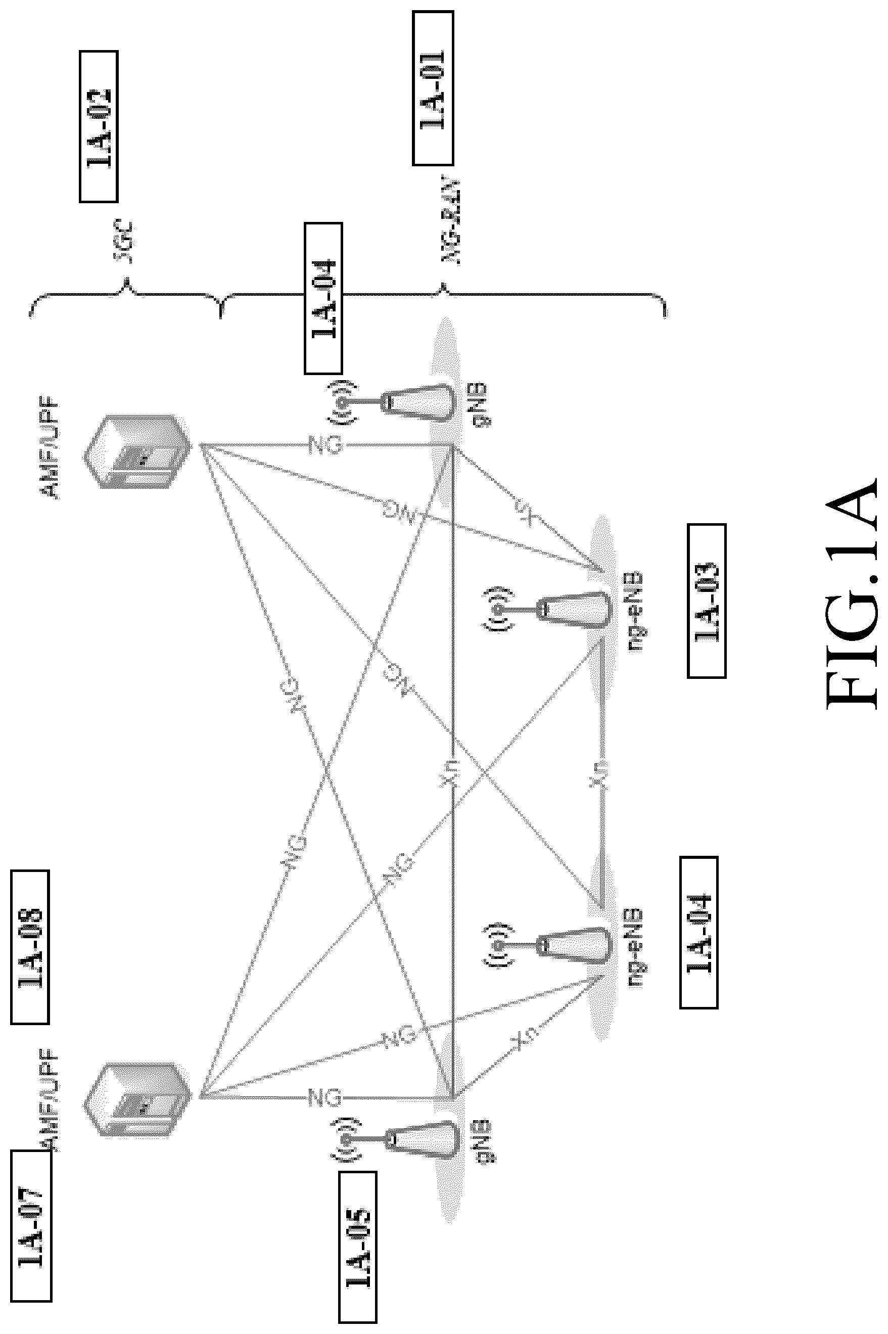
A is a diagram illustrating the architecture of an 5G system and a NG-RAN to which the disclosure may be applied.
5G system consists of NG-RAN 1 A- 01 and 5GC 1 A- 02 . An NG-RAN node is either:
•
• a gNB, providing NR user plane and control plane protocol terminations towards the UE; or • an ng-eNB, providing E-UTRA user plane and control plane protocol terminations towards the UE.
The gNBs 1 A- 05 or 1 A- 06 and ng-eNBs 1 A- 03 or 1 A- 04 are interconnected with each other by means of the Xn interface. The gNBs and ng-eNBs are also connected by means of the NG interfaces to the 5GC, more specifically to the AMF (Access and Mobility Management Function) and to the UPF (User Plane Function). AMF 1 A- 07 and UPF 1 A- 08 may be realized as a physical node or as separate physical nodes.
A gNB 1 A- 05 or 1 A- 06 or an ng-eNBs 1 A- 03 or 1 A- 04 hosts the functions listed below.
Functions for Radio Resource Management such as Radio Bearer Control, Radio Admission Control, Connection Mobility Control, Dynamic allocation of resources to UEs in uplink, downlink and sidelink(scheduling); and
•
• IP and Ethernet header compression, uplink data decompression and encryption of user data stream; and • Selection of an AMF at UE attachment when no routing to an MME can be determined from the information provided by the UE; and • Routing of User Plane data towards UPF; and • Scheduling and transmission of paging messages; and • Scheduling and transmission of broadcast information (originated from the AMF or O&M); and • Measurement and measurement reporting configuration for mobility and scheduling; and • Session Management; and • QoS Flow management and mapping to data radio bearers; and • Support of UEs in RRC_INACTIVE state; and • Radio access network sharing; and • Tight interworking between NR and E-UTRA; and • Support of Network Slicing.
The AMF 1 A- 07 hosts the functions such as NAS signaling, NAS signaling security, AS security control, SMF selection, Authentication, Mobility management and positioning management.
The UPF 1 A- 08 hosts the functions such as packet routing and forwarding, transport level packet marking in the uplink, QoS handling and the downlink, mobility anchoring for mobility etc.
B is a diagram illustrating a wireless protocol architecture in an 5G system to which the disclosure may be applied.
User plane protocol stack consists of SDAP 1 B- 01 or 1 B- 02 , PDCP 1 B- 03 or 1 B- 04 , RLC 1 B- 05 or 1 B- 06 , MAC 1 B- 07 or 1 B- 08 and PHY 1 B- 09 or 1 B- 10 . Control plane protocol stack consists of NAS 1 B- 11 or 1 B- 12 , RRC 1 B- 13 or 1 B- 14 , PDCP, RLC, MAC and PHY.
Each protocol sublayer performs functions related to the operations listed in the table 3.
TABLE 3
Sublayer Functions
NAS authentication, mobility management, security control etc
RRC System Information, Paging, Establishment, maintenance and release
of an RRC connection, Security functions, Establishment,
configuration, maintenance and release of Signalling Radio Bearers
(SRBs) and Data Radio Bearers (DRBs), Mobility, QoS management,
Detection of and recovery from radio link failure, NAS message
transfer etc.
SDAP Mapping between a QoS flow and a data radio bearer, Marking QoS
flow ID (QFI) in both DL and UL packets.
PDCP Transfer of data, Header compression and decompression, Ciphering
and deciphering, Integrity protection and integrity verification,
Duplication, Reordering and in-order delivery, Out-of-order delivery
etc.
RLC Transfer of upper layer PDUs, Error Correction through ARQ,
Segmentation and re-segmentation of RLC SDUs, Reassembly of
SDU, RLC re-establishment etc.
MAC Mapping between logical channels and transport channels,
Multiplexing/demultiplexing of MAC SDUs belonging to one or
different logical channels into/from transport blocks (TB) delivered
to/from the physical layer on transport channels, Scheduling
information reporting, Priority handling between UEs, Priority
handling between logical channels of one UE etc.
PHY Channel coding, Physical-layer hybrid-ARQ processing, Rate
matching, Scrambling, Modulation, Layer mapping, Downlink
Control Information, Uplink Control Information etc.
The terminal supports three RRC states. Table 4 lists the characteristics of each state.
TABLE 4
RRC state Characteristic
RRC_ PLMN selection; Broadcast of system information;
IDLE Cell re-selection mobility;
Paging for mobile terminated data is initiated by 5GC;
DRX for CN paging configured by NAS.
RRC_ PLMN selection; Broadcast of system information; Cell re-
INACTIVE selection mobility;
Paging is initiated by NG-RAN (RAN paging);
RAN-based notification area (RNA) is managed by NG-RAN;
DRX for RAN paging configured by NG-RAN;
5GC-NG-RAN connection (both C/U-planes) is established
for UE;
The UE AS context is stored in NG-RAN and the UE;
NG-RAN knows the RNA which the UE belongs to.
RRC_ 5GC-NG-RAN connection (both C/U-planes) is established
CONNECTED for UE; The UE AS context is stored in NG-RAN and the UE;
NG-RAN knows the cell which the UE belongs to;
Transfer of unicast data to/from the UE;
Network controlled mobility including measurements.
C is a diagram illustrating an RRC state transition.
Between RRC_CONNECTED 1 C- 11 and RRC_INACTIVE 1 C- 13 , a state transition occurs due to the exchange of the Resume message and the Release message containing the Suspend IE.
A state transition occurs between RRC_CONNECTED 1 C- 11 and RRC_IDLE 1 C- 15 through RRC connection establishment and RRC connection release.
SuspendConfig includes the following information.
<SuspendConfig>
•
• 1: The first terminal identifier: an identifier of a terminal that may be included in the ResumeRequest when a state transition to RRC_CONNECTED is made. It has a 40-bit length. • 2: The second terminal identifier: an identifier of a terminal that may be included in the Resume Request when a state transition to RRC_CONNECTED is made. It has a 24-bit length. • 3: ran-Paging Cycle: Paging cycle to be applied in RRC_INACTIVE state. • 4: ran-Notification AreaInfo: Configuration information of a ran-Notification Area consisting of a list of cells and the like. The terminal initiates a resume procedure when the ran_Notification Area is changed. • 5: t380: Timer related to the periodic resumption procedure. • 6: NextHopChangingCount (NCC): Counter used to derive new security keys after performing the resume procedure.
D is a diagram illustrating the architecture of an GNB to which the disclosure may be applied.
gNB 1 D- 11 or 1 D- 12 consists of a gNB-CU 1 D- 13 and one or more gNB-DU 1 D- 14 or 1 D- 15 . gNB-CU and gNB-DU are interconnected via F1 interface. A gNB-DU is connected to only one gNB-CU. gNB-CU provides RRC, SDAP and PDCP protocol sublayers. gNB-DU provides RLC, MAC and PHY protocol sublayers.
The UE monitors the PO for paging reception. In the current specification, different paging cycles may result in different POs in the IDLE and INACTIVE states. By ensuring consistent POs in the IDLE and INACTIVE states, paging can be more efficient for both the UE and the network.
A illustrates the operations of UE and DU and CU for paging.
The UE may use Discontinuous Reception (DRX) in RRC_IDLE and RRC_INACTIVE state in order to reduce power consumption. The UE monitors one paging occasion (PO) per DRX cycle. A PO is a set of PDCCH monitoring occasions and can consist of multiple time slots (e.g., subframe or OFDM symbol) where paging DCI can be sent. One Paging Frame (PF) is one Radio Frame and may contain one or multiple PO(s) or starting point of a PO.
The PF and PO for paging are determined by the following formulae:
•
• SFN for the PF is determined by: ( SFN+PF _offset)mod T =( T div N )*( UE _ ID mod N _ PF ) • Index (Ls), indicating the index of the PO is determined by: i _ s =floor ( UE _ ID/N _ PF )mod Ns
The following parameters are used for the calculation of PF and i_s above:
•
• T: DRX cycle of the UE (T is determined by the shortest of the UE specific DRX value(s), if configured by RRC and/or upper layers, and a default DRX value broadcast in system information. In RRC_IDLE state, if UE specific DRX is not configured by upper layers, the default value is applied). • N_PF: number of total paging frames in T and broadcasted in SIB 1 . • Ns: number of paging occasions for a PF and broadcasted in SIB 1 . • PF_offset: offset used for PF determination and broadcasted in SIB 1 . • UE_ID: 5G-S-TMSI mod 1024 • a UE specific DRX value for IDLE UE is allocated by AMF and configured by upper layers. a UE specific DRX value for INACTIVE UE is allocated by GNB and configured by RRC.
If UE specific DRX value configured by upper layers and UE specific DRX value configured by RRC are different, different i_s can be applied to each state. It bears two problems.
Firstly, UE must determine i_s again upon transition from RRC INACTIVE state to RRC IDLE state. Secondly, INACTIVE UE cannot monitor paging transmitted from AMF because the paging is transmitted in the PO calculated from the UE specific DRX cycle configured by AMF while UE monitors PO calculated from the UE specific DRX cycle configured by GNB.
To overcome the problem, CU calculates i_s based on IDLE mode DRX cycle and instructs DU to use the calculated i_s. UE calculates i_s based on IDLE mode DRX cycle even when it is in RRC_INACTIVE state.
5G-S-TMSI is a 5G S-Temporary Mobile Subscription Identifier, a temporary UE identity provided by the 5GC which uniquely identifies the UE within the tracking area. 5G-S-TMSI is allocated by AMF during tracking area update procedure or during registration procedure.
To ensure backward compatibility with the old release devices, SuspendConfig mandatorily includes ran-Paging-Cycle and optionally includes extended-ran-Paging-Cycle.
If SuspendConfig includes only ran-Paging-Cycle, UE specific DRX value configured by RRC is determined by ran-Paging-Cycle. If SuspendConfig includes both ran-Paging-Cycle and extended-ran-paging-cycle, UE specific DRX value configured by RRC is determined by extened-ran-Paging-Cycle.
In the following, i_s is called PO-Index as well.
In 2 A- 11 , DU 2 A- 03 transmits SIB1 on the Uu interface. SIB1 includes following information; a default DRX value, a joint-parameter-N_PF/PF_offset, a Ns and ranPagingIdlePO.
The default DRX value is used to derive the paging frames together with the joint parameter and other parameters. The default DRX value is one of predefined values; 32, 64, 128 and 256. The values indicate 32 radio frames, 64 radio frames, 128 radio frames and 256 radio frames respectively.
The joint-parameter-N_PF/PF_offset is used to derive N_PF and PF_offset.
The joint-parameter-N_PF/PF_offset can indicate one of five predefined values: oneT, halfT, quarterT, oneEighthT, oneSixteenthT.
The Ns indicates one of three predefined values: four, two, one.
ranPagingIdlePO indicates that the network supports to send RAN paging in PO that corresponds to the i_s as determined by UE in RRC_IDLE state.
UE 2 A- 01 camping on the cell controlled by the DU receives the SIB 1 . The UE determines PF based on at least in part of the above parameters.
In 2 A- 13 , UE determines PF and PO.
UE determines the PF based on UE_ID, N_PF1, PF_offset and T_PF.
If UE specific DRX value is configured by upper layers, UE in RRC_IDLE determines T_PF by the shortest of the default DRX value and the UE specific DRX value configured by upper layers.
If UE specific DRX value is not configured by upper layers, UE determines T_PF the default DRX value.
If UE specific DRX value configured by RRC is greater than 256, UE in RRC_INACTIVE determines T_PF the UE specific DRX value configured by RRC.
If UE specific DRX value configured by RRC is smaller than 256, UE in RRC_INACTIVE determines T_PF the shortest of the default DRX value and the UE specific DRX value configured by RRC.
UE determines N_PF1 based on the determined T_PF and a value indicated by the joint parameter. N_PF is calculated by dividing T_PF by 1 in case that the joint parameter indicates the 1st value, dividing T_PF by 2 in case that the parameter for N indicates the 2nd value, dividing T_PF by 4 in case that the parameter for N indicates the 3rd value, dividing T_PF 8 in case that the parameter for N indicates the 4th value and dividing T_PF 16 in case that the parameter for N indicates the 5th value.
UE determines the index of the PO based on UE_ID, N_PF2 and Ns. N_PF2 is determined by the joint parameter and T_PO. For UE in RRC_IDLE, T_PO and T_PF are same. For UE in RRC_INACTIVE, if the UE does not support to use the same i_s to determine PO in RRC_INACTIVE state as in RRC_IDLE state or if ran-PagingIndlePO is not broadcasted, T_PO and T_PF are same. For UE in RRC_INACTIVE, if the UE supports to use the same Ls to determine PO in RRC_INACTIVE state as in RRC_IDLE state and if ran-PagingIndlePO is broadcasted, T_PF is determined based on UE specific DRX value configured by RRC and T_PO is determined based on UE specific DRX value configured by upper layers.
In other words, In RRC_INACTIVE state, UE shall use the same PO-Index as for RRC_IDLE state if the UE supports to use the same i_s to determine PO in RRC_INACTIVE state as in RRC_IDLE state and if ran-PagingIndlePO is broadcasted.
In 2 A- 15 , CU 2 A- 05 receives RAN paging message from another CU over Xn interface. The purpose of the RAN Paging procedure is to enable a NG-RAN node to request paging of a UE in another NG-RAN node. RAN paging message includes following information; UE-Identity-Index-Value, UE-RAN-Paging-Identity, Paging-DRX and RAN-Paging-Area.
The RAN paging message can optionally include PO-info. The RAN paging message can optionally include extended-Paging-DRX.
UE-Identity-Index-Value is bit string of 10 bit. This IE is used by the target NG-RAN node to calculate the paging-frame. This IE corresponds to UE_ID.
UE-RAN-Paging-Identity is the-first-terminal-identifier of the UE to be paged.
Paging-DRX is UE-specific-DRX-value configured by RRC. This IE corresponds to ran-Paging-Cycle of the UE to be paged.
extended-Paging-DRX is UE-specific-DRX value configured by RRC. This IE corresponds to extended-ran-Paging-Cycle of the UE to be paged.
RAN-Paging-Area defines the paging area for RAN paging a UE in RRC_INACTIVE state. This IE corresponds to ran-Notification-AreaInfo of the UE to be paged.
CU generates a first paging message based on at least part of the RAN paging message. CU determines DUs to which the first paging message to be transmitted.
In 2 A- 17 , CU sends the first paging message to the determined DUs. The first paging message includes following information; UE-Identity-Index-Value and RAN-UE-Paging-Identity. The first paging message can optionally include PO-info. The first paging message includes either Paging-DRX or extended-Paging-DRX.
UE-Identity-Index-Value, RAN-UE-Paging-Identity, Paging-DRX, extended-Paging-DRX and PO-info included in the first paging message are respectively UE-Identity-Index-Value, UE-RAN-Paging-Identity, Paging-DRX, extended-Paging-DRX and PO-info received in RAN paging message.
CU includes Paging-DRX in the first paging message if the RAN paging message includes Paging-DRX but not include extended-Paging-DRX.
CU includes extended-Paging-DRX in the first paging message if the RAN paging message includes both Paging-DRX and extended-Paging-DRX.
The first paging message can be triggered by the CU 2 A- 05 itself. CU generates the first paging message for a UE in RRC_INACTIVE when DL data for the UE arrives.
CU determines UE-Identity-Index-Value by the 10 LSB bits of 5G-S-TMSI of the UE (i.e., UE-Identity-Index-Value=5G-S-TMSI mod 1024).
CU determines RAN-UE-Paging-Identity by the first terminal identity allocated to the UE.
CU determines Paging-DRX by ran-Paging-Cycle configured to the UE if the UE is configured only with ran-Paging-Cycle. CU determines extended-Paging-DRX by extended-ran-Paging-Cycle configured to the UE if the UE is configured with both ran-Paging-Cycle and extended-ran-Paging-Cycle.
If the UE has indicated in a UL RRC message for reporting UE capability that the UE supports to use the same i_s to determine PO in RRC_INACTIVE state as in RRC_IDLE state and if the DU broadcasts ran-PagingIndlePO, CU includes PO-info in the first paging message.
PO-info can include UE specific DRX cycle configured by upper layers. CU stores UE specific DRX cycle configured by upper layers which is informed by a AMF during the RRC connection of the corresponding UE.
PO-info can include N_PF determined based on UE specific DRX cycle configured by upper layers.
PO-info can include PO-index determined based on UE specific DRX cycle configured by upper layers.
In 2 A- 19 , DU determines PF and PO based on the information included in the first paging message.
DU determines PF based on UE-Identity-Index-Value, N_PF1, PF_offset and T_PF.
If Paging-DRX is included in the first paging message, T_PF is shortest of the default DRX value and Paging-DRX.
If extended-Paging-DRX is included in the first paging message, T_PF is extended-Paging-DRX.
N_PF1 is determined based on T_PF and the joint parameter.
DU determines PO-Index based on UE-Identity-Index-Value, N_PF2 and T_PO.
If PO-Info is not included in the first paging message, N_PF2 and T_PO are same as N_PF1 and T_PF respectively.
If PO-Info is included in the first paging message, N_PF2 and T_PO are determined as below.
If PO-Info includes UE specific DRX cycle configured by upper layers, T_PO is determined based on UE specific DRX cycle configured by upper layers indicated in PO-Info. N_PF2 is determined based on the determined T_PO.
If PO-Info includes N_PF determined based on UE specific DRX cycle configured by upper layers, N_PF2 is determined by N_PF indicated in PO-Info.
If PO-Info includes PO-Index determined based on UE specific DRX cycle configured by upper layers, PO-Index is determined by PO-Index indicated in PO-Info.
In 2 A- 21 , DU transmits RRC paging message at the determined PO of the determined PF. RRC paging message includes PagingUE-Identity. This IE is the first terminal identifier.
Upon receiving the RRC paging message, UE initiates RRC connection resumption procedure. In RRC connection resumption procedure, UE transmits a first UL RRC message containing the UE's stored second terminal identity. DU forward the UL RRC message to CU. CU searches UE context based on the received UE identity and decides whether to accept the request or not.
In 2 A- 23 , CU 2 A- 05 receives CN paging message from a AMF over NG interface. The purpose of the CN Paging procedure is to enable a AMF to request paging of a UE in another NG-RAN node. CN paging message includes following information; UE-Paging-Identity and Paging-DRX.
UE-Paging-Identity is 5G-S-TMSI of the UE to be paged.
Paging-DRX is UE-specific-DRX-value configured by upper layers.
CU generates a second paging message based on at least part of the CN paging message. CU determines DUs to which the second paging message to be transmitted.
In 2 A- 25 , CU sends the second paging message to the determined DUs. The second paging message includes following information; UE-Identity-Index-Value, CN-UE-Paging-Identity and Paging-DRX. The second paging message does not include PO-info.
CN-UE-Paging-Identity and Paging-DRX included in the second paging message are respectively UE-Paging-Identity and Paging-DRX received in CN paging message. UE-Identity-Index-Value is determined by CU based on UE-Paging-Identity received in CN paging message.
In 2 A- 27 , DU determines PF and PO based on the information included in the second paging message.
DU determines PF based on UE-Identity-Index-Value, N_PF1, PF_offset and T_PF.
If Paging-DRX is included in the second paging message, T_PF is shortest of the default DRX value and Paging-DRX.
If Paging-DRX is included in the second paging message, T_PF is the default DRX value.
N_PF1 is determined based on T_PF and the joint parameter.
DU determines PO-Index based on UE-Identity-Index-Value, N_PF1 and T_PF.
In 2 A- 29 , DU transmits RRC paging message at the determined PO. RRC paging message includes PagingUE-Identity. PagingUE-Identity is 5G-S-TMSI.
Upon receiving the RRC paging message, UE initiates RRC connection establishment procedure. In RRC connection establishment procedure, UE transmits a second UL RRC message containing part of the UE identity allocated by upper layers (I.E., 5G-S-TMSI) and a third UL RRC message containing the remaining part of the UE identity allocated by upper layers. DU forward the third UL RRC message to CU along with the CU performs call admission control and decides whether to accept the request or not.
B illustrates the operations of UE and GNB for paging.
In 2 B- 11 , GNB1 2 B- 03 transmits SIB1 on the Uu interface. SIB1 includes following information; a default DRX value, a joint-parameter-N_PF/PF_offset, a Ns and ranPagingIdlePO.
The default DRX value is used to derive the paging frames together with the joint parameter and other parameters. The default DRX value is one of predefined values; 32, 64, 128 and 256. The values indicate 32 radio frames, 64 radio frames, 128 radio frames and 256 radio frames respectively.
The joint-parameter-N_PF/PF_offset is used to derive N_PF and PF_offset.
The joint-parameter-N_PF/PF_offset can indicate one of five predefined values: oneT, hall T, quarterT, oneEighthT, oneSixteenthT.
The Ns indicates one of three predefined values: four, two, one.
ranPagingIdlePO indicates that the network supports to send RAN paging in PO that corresponds to the i_s as determined by UE in RRC_IDLE state.
UE 2 B- 01 camping on the cell controlled by the GNB1 receives the SIB 1 . The UE determines PF based on the above parameters.
In 2 B- 13 , UE determines PF and PO.
UE determines the PF based on UE_ID, N_PF1, PF_offset and T_PF.
If UE specific DRX value is configured by upper layers, UE in RRC_IDLE determines T_PF by the shortest of the default DRX value and the UE specific DRX value configured by upper layers.
If UE specific DRX value is not configured by upper layers, UE determines T_PF by the default DRX value.
If UE specific DRX value configured by RRC is greater than 256, UE in RRC_INACTIVE determines T_PF by the UE specific DRX value configured by RRC.
If UE specific DRX value configured by RRC is smaller than 256, UE in RRC_INACTIVE determines T_PF by the shortest of the default DRX value and the UE specific DRX value configured by RRC.
UE determines N_PF1 based on the determined T_PF and a value indicated by the joint parameter. N_PF is calculated by dividing T_PF by 1 in case that the joint parameter indicates the 1st value, dividing T_PF by 2 in case that the parameter for N indicates the 2nd value, dividing T_PF by 4 in case that the parameter for N indicates the 3rd value, dividing T_PF 8 in case that the parameter for N indicates the 4th value and dividing T_PF 16 in case that the parameter for N indicates the 5th value.
UE determines the index of the PO based on UE_ID, N_PF2 and Ns. N_PF2 is determined by the joint parameter and T_PO. For UE in RRC_IDLE, T_PO and T_PF are same. For UE in RRC_INACTIVE, if the UE does not support to use the same i_s to determine PO in RRC_INACTIVE state as in RRC_IDLE state or if ran-PagingIndlePO is not broadcasted, T_PO and T_PF are same. For UE in RRC_INACTIVE, if the UE supports to use the same Ls to determine PO in RRC_INACTIVE state as in RRC_IDLE state and if ran-PagingIndlePO is broadcasted, T_PF is determined based on UE specific DRX value configured by RRC and T_PO is determined based on UE specific DRX value configured by upper layers.
In other words, In RRC_INACTIVE state, UE shall use the same PO-Index as for RRC_IDLE state if the UE supports to use the same i_s to determine PO in RRC_INACTIVE state as in RRC_IDLE state and if ran-PagingIndlePO is broadcasted.
In 2 B- 15 , GNB1 2 B- 03 receives RAN paging message from GNB2 ( 2 B- 05 ) over Xn interface. The purpose of the RAN Paging procedure is to enable a NG-RAN node to request paging of a UE in another NG-RAN node. RAN paging message includes following information; UE-Identity-Index-Value, UE-RAN-Paging-Identity, Paging-DRX and RAN-Paging-Area.
The RAN paging message can optionally include PO-info. The RAN paging message can optionally include extended-Paging-DRX.
UE-Identity-Index-Value is a bit string of 10 bit. This IE is used by the target NG-RAN node to calculate the paging-frame. This IE corresponds to UE_ID.
UE-RAN-Paging-Identity is the-first-terminal-identifier of the UE to be paged.
Paging-DRX is UE-specific-DRX-value configured by RRC. This IE corresponds to ran-Paging-Cycle of the UE to be paged.
extended-Paging-DRX is UE-specific-DRX value configured by RRC. This IE corresponds to extended-ran-Paging-Cycle of the UE to be paged.
RAN-Paging-Area defines the paging area for RAN paging a UE in RRC_INACTIVE state. This IE corresponds to ran-Notification-AreaInfo of the UE to be paged.
GNB2 2 B- 05 generates the RAN paging message for a UE in RRC_INACTIVE when DL data for the UE arrives.
GNB2 determines UE-Identity-Index-Value by the 10 LSB bits of 5G-S-TMSI of the UE (i.e., UE-Identity-Index-Value=5G-S-TMSI mod 1024).
GNB2 determines RAN-UE-Paging-Identity by the first terminal identity allocated to the UE.
GNB2 determines Paging-DRX by ran-Paging-Cycle configured to the UE if the UE is configured only with ran-Paging-Cycle. GNB2 determines extended-Paging-DRX by extended-ran-Paging-Cycle configured to the UE if the UE is configured with both ran-Paging-Cycle and extended-ran-Paging-Cycle.
If the UE has indicated in a UL RRC message for reporting UE capability that the UE supports to use the same i_s to determine PO in RRC_INACTIVE state as in RRC_IDLE state and if the GNB1 broadcasts ran-PagingIndlePO, GNB2 includes PO-info in RAN paging message.
PO-info can include UE specific DRX cycle configured by upper layers. GNB2 stores UE specific DRX cycle configured by upper layers which is informed by a AMF during the RRC connection of the corresponding UE.
PO-info can include N_PF determined based on UE specific DRX cycle configured by upper layers.
PO-info can include PO-index determined based on UE specific DRX cycle configured by upper layers.
In 2 B- 19 , GNB1 determines PF and PO based on the information included in RAN paging message.
GNB1 determines PF based on UE-Identity-Index-Value, N_PF1, PF_offset and T_PF.
If Paging-DRX is included in RAN paging message, T_PF is shortest of the default DRX value and Paging-DRX.
If extended-Paging-DRX is included in RAN paging message, T_PF is extended-Paging-DRX.
N_PF1 is determined based on T_PF and the joint parameter.
GNB1 determines PO-Index based on UE-Identity-Index-Value, N_PF2 and T_PO.
If PO-Info is not included in RAN paging message, N_PF2 and T_PO are same as N_PF1 and T_PF respectively.
If PO-Info is included in RAN paging message, N_PF2 and T_PO are determined as below.
If PO-Info includes UE specific DRX cycle configured by upper layers, T_PO is determined based on UE specific DRX cycle configured by upper layers indicated in PO-Info. N_PF2 is determined based on the determined TPO.
If PO-Info includes N_PF determined based on UE specific DRX cycle configured by upper layers, N_PF2 is determined by N_PF indicated in PO-Info.
If PO-Info includes PO-Index determined based on UE specific DRX cycle configured by upper layers, PO-Index is determined by PO-Index indicated in PO-Info.
In 2 B- 21 , GNB1 transmits RRC paging message at the determined PO of the determined PF. RRC paging message includes PagingUE-Identity. This IE is the first terminal identifier.
Upon receiving the RRC paging message, UE initiates RRC connection resumption procedure. In RRC connection resumption procedure, UE transmits a first UL RRC message containing the UE's stored second terminal identity. GNB1 forward the UL RRC message to GNB2. GNB2 searches UE context based on the received UE identity and decides whether to accept the request or not.
In 2 B- 23 , GNB1 2 B- 03 receives CN paging message from a AMF 2 B- 07 over NG interface. The purpose of the CN Paging procedure is to enable a AMF to request paging of a UE in another NG-RAN node. CN paging message includes following information; UE-Paging-Identity and Paging-DRX.
UE-Paging-Identity is 5G-S-TMSI of the UE to be paged.
Paging-DRX is UE-specific-DRX-value configured by upper layers.
In 2 B- 27 , GNB1 determines PF and PO based on the information included in the second paging message.
GNB1 determines PF based on UE-Identity-Index-Value, N_PF1, PF_offset and T_PF.
If Paging-DRX is included in the second paging message, T_PF is shortest of the default DRX value and Paging-DRX.
If Paging-DRX is not included in the second paging message, T_PF is the default DRX value.
N_PF1 is determined based on T_PF and the joint parameter.
GNB1 determines PO-Index based on UE-Identity-Index-Value, N_PF1 and T_PF.
In 2 B- 29 , GNB1 transmits RRC paging message at the determined PO. RRC paging message includes PagingUE-Identity. PagingUE-Identity is 5G-S-TMSI.
Upon receiving the RRC paging message, UE initiates RRC connection establishment procedure. In RRC connection establishment procedure, UE transmits a second UL RRC message containing part of the UE identity allocated by upper layers (i.e., 5G-S-TMSI) and a third UL RRC message containing the remaining part of the UE identity allocated by upper layers. GNB1 forward the third UL RRC message to GNB1 along with the 5G-S-TMSI. GNB1 performs call admission control and decides whether to accept the request or not.
A illustrates the operation of a base station.
In step 3 A- 11 , the base station transmits SystemInformationBlock1.
In step 3 A- 13 , the base station receives a paging message from the second base station or AMF.
In step 3 A- 15 , the base station determines the index of the Paging-Occasion based at least in part on the information included in the paging message.
In step 3 A- 17 , in response to receiving a paging message, the base station transmits an RRC paging message through a paging channel to the paging-occasion determined based on the index of the paging-occasion and the PF.
The SystemInformationBlock1 includes parameters for Default-DRX-Value, Number-of-Paging-Occasion, and Number-of-Paging-Frames.
The parameter for the Number-of-Paging-Frames indicates a first value, a second value, a third value, a fourth value, or a fifth value.
The paging message includes at least a paging DRX.
When the paging message includes Paging-Occasion-Information, and the paging message is received from a second base station, the index of the Paging-Occasion is determined based on the first set and the Paging-Occasion-Information.
The first set consists of the UE-Identifier-index-value, the Number-of-Paging-Occasion, the default DRX value, and the Number-of-Paging-Frames.
The Paging-Occasion-Information is UE specific DRX value configured by upper layers.
If the paging message is received at the second base station, the paging message includes a first paging identifier, and if the paging message is received at the AMF, the paging message includes a second paging identifier.
The first paging identifier is a temporary identifier assigned by the second base station, and the second paging identifier is a temporary identifier assigned by the AMF.
In response to receiving a paging message from a second base station, the RRC paging message includes a first paging identifier, and in response to receiving a paging message from AMF, the paging message includes a second paging identifier.
The UE-Identifier-index-value is derived from the second paging identifier, and the second paging identifier is a temporary identifier assigned by AMF.
If the parameter for Number-of-Paging-Frames is the first value, Number-of-Paging-Frames is determined by dividing the DRX cycle of the terminal by 1. If the parameter for Number-of-Paging-Frames is the second value, Number-of-Paging-Frames is determined by dividing the DRX cycle of the terminal by 2. If the parameter for Number-of-Paging-Frames is the third value, Number-of-Paging-Frames is determined by dividing the DRX cycle of the terminal by 4. If the parameter for Number-of-Paging-Frames is the fourth value, Number-of-Paging-Frames is determined by dividing the DRX cycle of the terminal by 8. If the parameter for Number-of-Paging-Frames is the fifth value, Number-of-Paging-Frames is determined by dividing the DRX cycle of the terminal by 16.
If Paging-Occasion-Information is not included in the paging message, the DRX cycle of the terminal is the shortest of the default DRX value broadcast in SIB1 and the paging DRX included in the paging message.
If the paging message includes Paging-Occasion-Information, the UE's DRX cycle is the shortest among the default DRX value broadcast in SIB1 and the UE specific DRX value configured by upper layers.
A is a block diagram illustrating the internal structure of a UE to which the disclosure is applied.
Referring to the diagram, the UE includes a controller 4 A- 01 , a storage unit 4 A- 02 , a transceiver 4 A- 03 , a main processor 4 A- 04 and I/O unit 4 A- 05 .
The controller 4 A- 01 controls the overall operations of the UE in terms of mobile communication. For example, the controller 4 A- 01 receives/transmits signals through the transceiver 4 A- 03 . In addition, the controller 4 A- 01 records and reads data in the storage unit 4 A- 02 . To this end, the controller 4 A- 01 includes at least one processor. For example, the controller 4 A- 01 may include a communication processor (CP) that performs control for communication and an application processor (AP) that controls the upper layer, such as an application program. The controller controls storage unit and transceiver such that UE operations illustrated in A and B are performed.
The storage unit 4 A- 02 stores data for operation of the UE, such as a basic program, an application program, and configuration information. The storage unit 4 A- 02 provides stored data at a request of the controller 4 A- 01 .
The transceiver 4 A- 03 consists of a RF processor, a baseband processor and one or more antennas. The RF processor performs functions for transmitting/receiving signals through a wireless channel, such as signal band conversion, amplification, and the like. Specifically, the RF processor up-converts a baseband signal provided from the baseband processor into an RF band signal, transmits the same through an antenna, and down-converts an RF band signal received through the antenna into a baseband signal. The RF processor may include a transmission filter, a reception filter, an amplifier, a mi10r, an oscillator, a digital-to-analog converter (DAC), an analog-to-digital converter (ADC), and the like. The RF processor may perform MIMO and may receive multiple layers when performing the MIMO operation. The baseband processor performs a function of conversion between a baseband signal and a bit string according to the physical layer specification of the system. For example, during data transmission, the baseband processor encodes and modulates a transmission bit string, thereby generating complex symbols. In addition, during data reception, the baseband processor demodulates and decodes a baseband signal provided from the RF processor, thereby restoring a reception bit string.
The main processor 4 A- 04 controls the overall operations other than mobile operation. The main processor 4 A- 04 process user input received from I/O unit 4 A- 05 , stores data in the storage unit 4 A- 02 , controls the controller 4 A- 01 for required mobile communication operations and forward user data to I/O unit 4 A- 05 .
I/O unit 4 A- 05 consists of equipment for inputting user data and for outputting user data such as a microphone and a screen. I/O unit 4 A- 05 performs inputting and outputting user data based on the main processor's instruction.
B is a block diagram illustrating the structure of a DU according to the disclosure.
As illustrated in the diagram, the DU includes a controller 4 B- 01 , a storage unit 4 B- 02 , a transceiver 4 B- 03 and a backhaul interface unit 4 B- 04 .
The controller 4 B- 01 controls the overall operations of the DU. For example, the controller 4 B- 01 receives/transmits signals through the transceiver 4 B- 03 , or through the backhaul interface unit 4 B- 04 . In addition, the controller 4 B- 01 records and reads data in the storage unit 4 B- 02 . To this end, the controller 4 B- 01 may include at least one processor. The controller controls transceiver, storage unit and backhaul interface such that DU operation illustrated in A are performed.
The storage unit 4 B- 02 stores data for operation of the main DU, such as a basic program, an application program, and configuration information. Particularly, the storage unit 4 B- 02 may store information regarding a bearer allocated to an accessed UE, a measurement result reported from the accessed UE, and the like. In addition, the storage unit 4 B- 02 may store information serving as a criterion to deter mine whether to provide the UE with multi-connection or to discontinue the same. In addition, the storage unit 4 B- 02 provides stored data at a request of the controller 4 B- 01 .
The transceiver 4 B- 03 consists of a RF processor, a baseband processor and plurality of antennas. The RF processor performs functions for transmitting/receiving signals through a wireless channel, such as signal band conversion, amplification, and the like. Specifically, the RF processor up-converts a baseband signal provided from the baseband processor into an RF band signal, transmits the same through an antenna, and down-converts an RF band signal received through the antenna into a baseband signal. The RF processor may include a transmission filter, a reception filter, an amplifier, a mixer, an oscillator, a DAC, an ADC, and the like. The RF processor may perform a down link MIMO operation by transmitting at least one layer. The baseband processor performs a function of conversion between a baseband signal and a bit string according to the physical layer specification of the first radio access technology. For example, during data transmission, the baseband processor encodes and modulates a transmission bit string, thereby generating complex symbols. In addition, during data reception, the baseband processor demodulates and decodes a baseband signal provided from the RF processor, thereby restoring a reception bit string.
The backhaul interface unit 4 B- 04 provides an interface for communicating with other nodes inside the network. The backhaul interface unit 4 B- 04 converts a bit string transmitted from the DU to another node, for example, another CU, into a physical signal, and converts a physical signal received from the other node into a bit string.
Figures (9)
Citations
This patent cites (17)
- US2018/0270792
- US2018/0270894
- US2018/0279256
- US2019/0313475
- US2019/0349886
- US2021/0176729
- US2021/0212153
- US2022/0132464
- US2023/0156660
- US2023/0292288
- US2024/0224231
- US2024/0406933
- US2025/0219748
- US1020170125296
- US1020190132429
- US1020200105512
- USWO-2021127846