Abstract
A reflector driving device includes: a reflector-retaining member configured to retain a reflector that refracts light; a first support member configured to support the reflector-retaining member so as to be swingable about a first axis; a second support member configured to support the first support member so as to be swingable about a second axis having an axis-line direction perpendicular to an axis-line direction of the first axis; a first driving mechanism configured to swing the reflector-retaining member about the first axis; a second driving mechanism configured to swing the first support member about the second axis; a first biasing member configured to bias the reflector-retaining member toward the first support member; and a second biasing member configured to bias the first support member toward the second support member.
Claims (20)
1 . A reflector driving device, comprising: a reflector-retaining member configured to retain a reflector that refracts light; a first support member configured to support the reflector-retaining member so as to be swingable about a first axis; a second support member configured to support the first support member so as to be swingable about a second axis having an axis-line direction perpendicular to an axis-line direction of the first axis; a first driving mechanism configured to swing the reflector-retaining member about the first axis; a second driving mechanism configured to swing the first support member about the second axis; a first biasing member configured to bias the reflector-retaining member toward the first support member; and a second biasing member configured to bias the first support member toward the second support member, wherein the second driving mechanism includes a second magnetic field-generating member movable along with the first support member, and a second coil facing the second magnetic field-generating member, in a direction in which the second biasing member biases the first support member, a magnetic member disposed to be spaced from the second magnetic field-generating member is provided, and a restoring force of the second biasing member is greater than an attracting force between the second magnetic field generating member and the magnetic member.
20 . A reflector driving device, comprising: a reflector-retaining member configured to retain a reflector that refracts light; a first support member configured to support the reflector-retaining member so as to be swingable about a first axis; a second support member configured to support the first support member so as to be swingable about a second axis having an axis-line direction perpendicular to an axis-line direction of the first axis; a first driving mechanism configured to swing the reflector-retaining member about the first axis; a second driving mechanism configured to swing the first support member about the second axis; a first biasing member configured to bias the reflector-retaining member toward the first support member; and a second biasing member configured to bias the first support member toward the second support member, wherein the first biasing member includes a first leaf spring; wherein the second biasing member includes a second leaf spring that is different from the first leaf spring included in the first biasing member, and wherein the first leaf spring and the second leaf spring are disposed at different positions in a biasing direction in which the first biasing member biases the reflector-retaining member, so as to have a portion where the first leaf spring and the second leaf spring face each other with a gap in the biasing direction.
Show 18 dependent claims
2 . The reflector driving device according to claim 1 , wherein: a first direction in which the first biasing member biases the reflector-retaining member and a second direction in which the second biasing member biases the first support member are identical; and the first direction and the second direction are perpendicular to the axis-line direction of the first axis and the axis-line direction of the second axis.
3 . The reflector driving device according to claim 1 , wherein: the first biasing member includes a first leaf spring; and the second biasing member includes a second leaf spring that is different from the first leaf spring included in the first biasing member.
4 . The reflector driving device according to claim 3 , wherein the first leaf spring and the second leaf spring are disposed at different positions in a biasing direction in which the first biasing member biases the reflector-retaining member, so as to have a portion where the first leaf spring and the second leaf spring face each other with a gap in the biasing direction.
5 . The reflector driving device according to claim 4 , wherein the second leaf spring is disposed farther away from the first axis than the first leaf spring.
6 . The reflector driving device according to claim 4 , wherein: the first leaf spring includes a first fixing portion to be fixed to the reflector-retaining member, a second fixing portion to be fixed to the first support member, and a first elastic arm portion provided between the first fixing portion and the second fixing portion; the second leaf spring includes a third fixing portion to be fixed to the first support member, a fourth fixing portion to be fixed to the second support member, and a second elastic arm portion provided between the third fixing portion and the fourth fixing portion; and in an initial state in which the first driving mechanism and the second driving mechanism do not drive, plate surfaces of the first fixing portion, the second fixing portion, the third fixing portion, and the fourth fixing portion are parallel to each other.
7 . The reflector driving device according to claim 6 , wherein: the first leaf spring includes a first spring member and a second spring member that are disposed to be spaced from each other; each of the first spring member and the second spring member includes two first elastic arm portions each connecting the first fixing portion and the second fixing portion to each other, each of the two first elastic arm portions being the first elastic arm portion; as viewed along the biasing direction, the first axis is positioned between the two first elastic arm portions of the first spring member and positioned between the two first elastic arm portions of the second spring member; the second leaf spring includes a third spring member and a fourth spring member that are disposed to be spaced from each other; each of the third spring member and the fourth spring member includes two second elastic arm portions each connecting the third fixing portion and the fourth fixing portion to each other, each of the two second elastic arm portions being the second elastic arm portion; and as viewed along the biasing direction, the first axis is positioned between the two second elastic arm portions of the third spring member and positioned between the two second elastic arm portions of the fourth spring member.
8 . The reflector driving device according to claim 4 , wherein: the first leaf spring includes a first fixing portion to be fixed to the reflector-retaining member, a second fixing portion to be fixed to the first support member, and a first elastic arm portion provided between the first fixing portion and the second fixing portion; the second leaf spring includes a third fixing portion to be fixed to the first support member, a fourth fixing portion to be fixed to the second support member, and a second elastic arm portion provided between the third fixing portion and the fourth fixing portion; the first elastic arm portion includes a plurality of winding portions and a plurality of extending portions each extending from both ends of each of the plurality of winding portions; the second elastic arm portion includes a plurality of winding portions and a plurality of extending portions each extending from both ends of each of the plurality of winding portions; and the first elastic arm portion and the second elastic arm portion are disposed so as to partially face each other in the biasing direction, and in a portion where the first elastic arm portion and the second elastic arm portion partially face each other in the biasing direction, the first elastic arm portion and the second elastic arm portion are disposed such that the extending portions of the first elastic arm portion extend along the extending portions of the second elastic arm portion.
9 . The reflector driving device according to claim 1 , wherein: the first biasing member and the second biasing member are formed of an identical spring member, the spring member being provided between the reflector-retaining member and the second support member; and the spring member serves as both of the first biasing member and the second biasing member.
10 . The reflector driving device according to claim 9 , wherein: the spring member is formed of a leaf spring; the spring member includes a first fixing portion to be fixed to the reflector-retaining member, a second fixing portion to be fixed to the second support member, and an elastic arm portion that connects the first fixing portion and the second fixing portion to each other; and in an initial state in which the first driving mechanism and the second driving mechanism do not drive, the first fixing portion and the second fixing portion are parallel to each other.
11 . The reflector driving device according to claim 10 , wherein: the spring member includes a first spring member and a second spring member that are disposed to be spaced from each other; each of the first spring member and the second spring member includes two elastic arm portions each connecting the first fixing portion and the second fixing portion to each other, each of the two elastic arm portions being the elastic arm portion; and as viewed along a biasing direction in which the first biasing member biases the reflector-retaining member, the first axis is positioned between the two elastic arm portions of the first spring member and positioned between the two elastic arm portions of the second spring member.
12 . The reflector driving device according to claim 1 , further comprising: a first shank portion via which the reflector-retaining member is connected so as to be swingable about the first axis; and a second shank portion via which the first support member is connected so as to be swingable about the second axis, wherein in a biasing direction in which the first biasing member biases the reflector-retaining member, a position of the first shank portion and a position of the second shank portion are different from each other.
13 . The reflector driving device according to claim 12 , wherein: the first shank portion includes a portion integrally formed with the reflector-retaining member and a portion integrally formed with the first support member; and/or the second shank portion includes a portion integrally formed with the first support member and a portion integrally formed with the second support member.
14 . The reflector driving device according to claim 12 , wherein: the first shank portion includes a ball disposed between the reflector-retaining member and the first support member; and/or the second shank portion includes a ball disposed between the first support member and the second support member.
15 . The reflector driving device according to claim 1 , wherein: the first driving mechanism includes a first magnetic field-generating member movable along with the reflector-retaining member, and a first coil facing the first magnetic field-generating member; and the first coil and the second coil, and the second support member are disposed so as to be unmovable relative to each other.
16 . The reflector driving device according to claim 15 , wherein the first coil and the second coil are provided on a wiring board, and the wiring board is fixed to the second support member.
17 . The reflector driving device according to claim 15 , wherein: the second magnetic field-generating member includes a magnet disposed in a first mounting portion of the first support member, and a magnet disposed in a second mounting portion of the first support member, the magnet disposed in the first mounting portion and the magnet disposed in the second mounting portion are disposed so as to face each other via a plane that is orthogonal to the first axis and includes the second axis; and the second coil includes a coil provided correspondingly to the magnet disposed in the first mounting portion, and a coil provided correspondingly to the magnet disposed in the second mounting portion.
18 . The reflector driving device according to claim 17 , wherein: the magnetic member includes a first magnetic member corresponding to the magnet disposed in the first mounting portion, and a second magnetic member corresponding to the magnet disposed in the second mounting portion; and the magnetic member is embedded in the second support member.
19 . The reflector driving device according to claim 1 , wherein: the first axis is orthogonal to a plane including an optical axis of incident light incident on the reflector and an optical axis of reflected light reflected by the reflector; and the second axis is parallel to the optical axis of the incident light.
Full Description
Show full text →
CROSS-REFERENCE TO RELATED APPLICATION
This application is a continuation application of International Application No. PCT/JP2022/007410 filed on Feb. 22, 2022, and designated the U.S., which is based upon and claims priority to Japanese Patent Application No. 2021-027898, filed on Feb. 24, 2021, the entire contents of which are incorporated herein by reference.
BACKGROUND
1. Field of the Invention
The present disclosure relates to a reflector driving device mounted in, for example, portable devices with cameras.
2. Description of the Related Art
Patent Document 1 discloses an image-capturing device including an anti-vibration unit configured to support a prism so as to be swingable about two swing axes. This anti-vibration unit includes: a first holder block that holds the prism and is swingable about a first swing axis; a second holder block that holds the first holder block so as to be swingable and is swingable about a second swing axis; and an anti-vibration base that supports the second holder block so as to be swingable. The first holder block and the second holder block are biased so as to become closer to each other with a tension spring extending along a first rotation axis.
CITATION LIST
Patent Document
Patent Document 1: Japanese Laid-Open Patent Publication No. 2020-177067
The swing mechanism of this anti-vibration unit is configured by a shaft inserted into bushes disposed for the two swing axes. A clearance is provided between the shaft and the bushes so that the shaft can rotate. However, with too small a clearance being provided, the shaft cannot rotate. Therefore, the dimensional tolerances of the shaft and the bushes are set to be relatively large so that the clearance does not become small excessively.
However, when the clearance between the shaft and the bushes is too large, backlash occurs between the shaft and the bushes and may give an adverse influence to swing of the prism.
In view thereof, it is desired to provide a reflector driving device that can more stably swing a reflector such as a prism.
SUMMARY
A reflector driving device according to embodiments of the present invention includes: a reflector-retaining member configured to retain a reflector that refracts light; a first support member configured to support the reflector-retaining member so as to be swingable about a first axis; a second support member configured to support the first support member so as to be swingable about a second axis having an axis-line direction perpendicular to an axis-line direction of the first axis; a first driving mechanism configured to swing the reflector-retaining member about the first axis; a second driving mechanism configured to swing the first support member about the second axis; a first biasing member configured to bias the reflector-retaining member toward the first support member; and a second biasing member configured to bias the first support member toward the second support member.
BRIEF DESCRIPTION OF DRAWINGS
is a perspective view of a reflector driving device.
is a schematic view of a camera module including the reflector driving device of .
is an exploded perspective view of the reflector driving device of .
A is a perspective view of a fixing member.
B is an exploded detailed view of the fixing member.
is a front view of a biasing member.
A is a right-hand lateral view of a driving mechanism.
B is a top view of the driving mechanism.
A is an exploded perspective front view of a moving member as viewed from the upper right diagonal direction.
B is an exploded perspective front view of the moving member as viewed from the upper left diagonal direction.
C is an exploded perspective back view of the moving member as viewed from the lower right diagonal direction.
A is a top view of a combination of the reflector-retaining member and a first support member.
B is a cross-sectional view of the combination of the reflector-retaining member and the first support member.
C is a cross-sectional view of the combination of the reflector-retaining member and the first support member.
A is a top view of a combination of the first support member and a second support member.
B is a cross-sectional view of the combination of the first support member and the second support member.
C is a cross-sectional view of the combination of the first support member and the second support member.
A is a perspective front view of the biasing member as viewed from the upper right diagonal direction, with the biasing member being disposed between the reflector-retaining member and the second support member.
B is a perspective front view of the biasing member as viewed from the upper left diagonal direction, with the biasing member being disposed between the reflector-retaining member and the second support member.
is a right-hand lateral view of the biasing member disposed between the reflector-retaining member and the second support member.
is an exploded perspective view of another configuration example of the reflector driving device.
A is an exploded perspective front view of the moving member of the reflector driving device of , as viewed from the upper right diagonal direction.
B is an exploded perspective front view of the moving member of the reflector driving device of , as viewed from the upper left diagonal direction.
C is an exploded perspective back view of the moving member of the reflector driving device of , as viewed from the lower right diagonal direction.
A is an enlarged view of a first shank portion.
B is an enlarged view of the first shank portion.
A is an enlarged view of a second shank portion.
B is an enlarged view of the second shank portion.
is an exploded perspective view of still another configuration example of the reflector driving device.
A is a perspective view of the fixing member of the reflector driving device of .
B is a perspective view of the fixing member of the reflector driving device of .
is a front view of the biasing member of the reflector driving device of .
A is a perspective front view of the biasing member as viewed from the upper right diagonal direction, with the biasing member being attached to the reflector-retaining member, the first support member, and the second support member of the reflector driving device of .
B is a perspective front view of a first biasing member as viewed from the upper right diagonal direction, with the first biasing member being attached to the reflector-retaining member and the first support member of the reflector driving device of .
C is a perspective front view of a second biasing member as viewed from the upper right diagonal direction, with the second biasing member being attached to the first support member and the second support member of the reflector driving device of .
D is a perspective front view of the first biasing member and the second biasing member of the reflector driving device of , as viewed from the upper right diagonal direction.
A is a front view of the first biasing member and the second biasing member of the reflector driving device of .
B is a top view of the first biasing member and the second biasing member of the reflector driving device of .
is a perspective view of the reflector-retaining member of the reflector driving device of .
is a perspective view of the first support member of the reflector driving device of .
is a partial front view of the biasing member of the reflector driving device of .
DETAILED DESCRIPTION
Embodiments
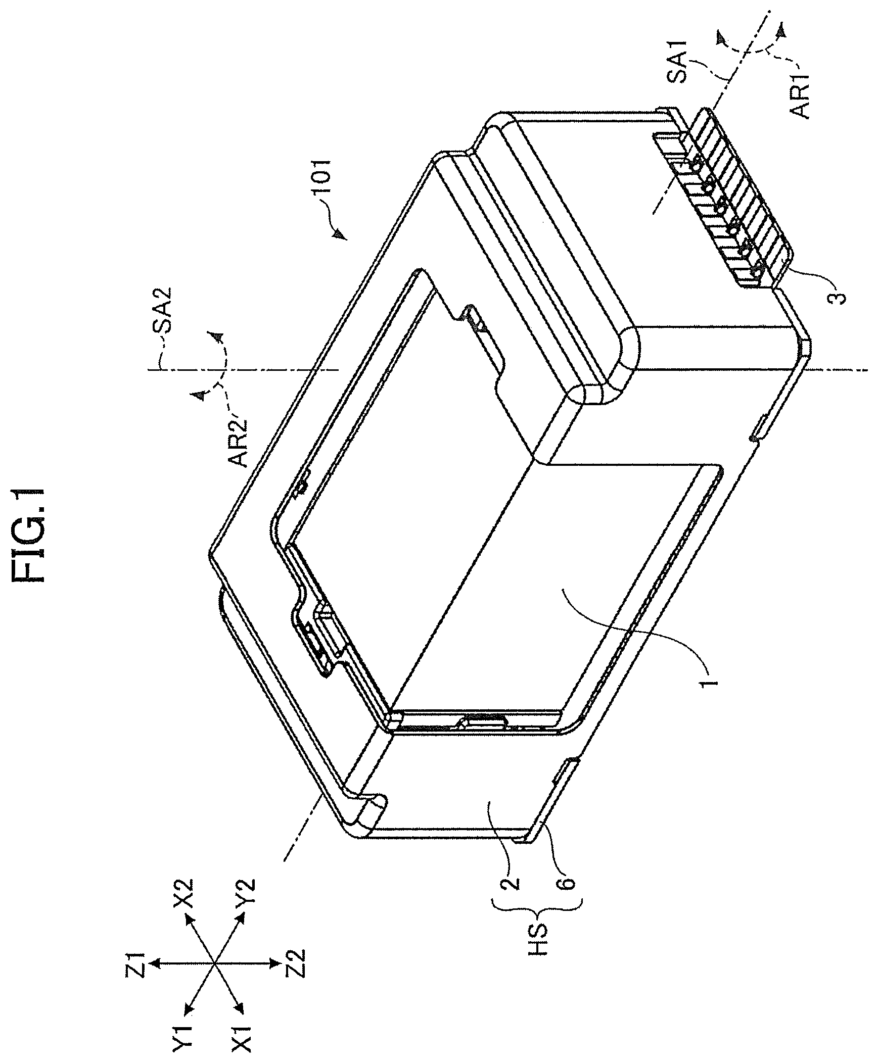
Hereinafter, a reflector driving device 101 according to the embodiments of the present invention will be described with reference to the drawings. is a perspective view of the reflector driving device 101 . is a schematic view of a camera module in a camera-equipped portable device including the reflector driving device 101 . is an exploded perspective view of the reflector driving device 101 .
In to , X 1 denotes one direction of an X axis forming a three-dimensional rectangular coordinate system, and X 2 denotes the other direction of the X axis. Also, Y 1 denotes one direction of a Y axis forming the three-dimensional rectangular coordinate system, and Y 2 denotes the other direction of the Y axis. Likewise, Z 1 denotes one direction of a Z axis forming the three-dimensional rectangular coordinate system, and Z 2 denotes the other direction of the Z axis. In the present embodiment, an X 1 side of the reflector driving device 101 corresponds to a front side (front-face side) of the reflector driving device 101 , and an X 2 side of the reflector driving device 101 corresponds to a back side (rear-face side) of the reflector driving device 101 . Also, a Y 1 side of the reflector driving device 101 corresponds to a left-hand side of the reflector driving device 101 , and a Y 2 side of the reflector driving device 101 corresponds to a right-hand side of the reflector driving device 101 . Further, a Z 1 side of the reflector driving device 101 corresponds to an upper side of the reflector driving device 101 , and a Z 2 side of the reflector driving device 101 corresponds to a lower side of the reflector driving device 101 . The same applies to the other drawings.
As illustrated in , the reflector driving device 101 is configured to swing a reflector 1 about a swing axis SA 1 and a swing axis SA 2 . The reflector driving device 101 is used as, for example, an actuator for camera shake correction in the camera module. In the present embodiment, the swing axis SA 1 serving as the first axis is an axis in parallel to the Y axis, and the swing axis SA 2 serving as the second axis is an axis in parallel to the Z axis. Note that, the swing axis SA 1 serving as the first axis may be an axis in parallel to the Z axis. In this case, the swing axis SA 2 serving as the second axis may be an axis in parallel to the Y axis.
As illustrated in , the reflector driving device 101 is typically disposed at a position closer to a subject than a lens unit LU. The reflector driving device 101 is configured such that light LT from the subject is reflected by the reflector 1 and the reflected light reaches an image sensor IS through the lens unit LU.
Specifically, as illustrated in , the reflector driving device 101 includes a moving member MB and a fixing member FB. The moving member MB is housed in a housing HS of the fixing member FB. The housing HS includes a cover member 2 and a base member (second support member 6 ). In the present embodiment, a cover member 2 is formed of a non-magnetic metal, and the second support member 6 serving as the base member is formed of a synthetic resin.
The reflector driving device 101 is configured such that a driving mechanism MD can swing the moving member MB relative to the fixing member FB. Specifically, as illustrated in and , the reflector driving device 101 is configured to rotate the reflector 1 relative to the housing HS about the swing axis SA 1 as indicated by a double-headed arrow AR 1 and about the swing axis SA 2 as indicated by a double-headed arrow AR 2 .
The moving member MB is a member supported by the fixing member FB. As illustrated in , the moving member MB includes the reflector 1 , a reflector-retaining member 4 , a first support member and a magnetic field-generating member 7 .
The reflector 1 is an optical element for refracting light. Specifically, as illustrated in , the reflector 1 is configured to reflect the light LT incident from the subject toward the lens unit LU. In the present embodiment, the reflector 1 is a prism. The reflector 1 may be a mirror.
The reflector-retaining member 4 is configured to retain the reflector 1 . In the present embodiment, the reflector-retaining member 4 is formed of a synthetic resin. The reflector 1 is bonded via an adhesive to the reflector-retaining member 4 .
The first support member 5 is configured to support the reflector-retaining member 4 so that the reflector-retaining member 4 is swingable about the swing axis SA 1 serving as the first axis. In the present embodiment, the first support member 5 is formed of a synthetic resin.
The magnetic field-generating member 7 is a constituent member of the driving mechanism MD. In the present embodiment, the magnetic field-generating member 7 is formed of bipolar-magnetized permanent magnets and includes a middle magnet 7 C, a left-hand magnet 7 L, and a right-hand magnet 7 R. The middle magnet 7 C is formed of a combination of two dipole magnets, and fixed via an adhesive to a lower (Z 2 -side) surface of the reflector-retaining member 4 . The left-hand magnet 7 L is formed of a combination of two dipole magnets, and fixed via an adhesive to the left-hand wall portion of the first support member 5 . The right-hand magnet 7 R is formed of a combination of two dipole magnets, and fixed via an adhesive to the right-hand wall portion of the first support member 5 . In , for ease of understanding, the permanent magnet is given a rough cross pattern in the N pole thereof and a fine cross pattern in the S pole thereof. The same applies to the other drawings. Note that, the middle magnet 7 C, the left-hand magnet 7 L, the right-hand magnet 7 R, or any combination thereof may be formed of one quadrupole magnet.
The fixing member FB is configured to support the moving member MB. Specifically, as illustrated in A and B , the fixing member FB includes a wiring board 3 , the second support member 6 , a coil 8 , and a sensor 10 . A and B are detailed views of the fixing member FB. Specifically, A is a perspective view of the fixing member FB, and B is an exploded perspective view of the fixing member FB. Note that, in A and B , for ease of understanding, the cover member 2 is not illustrated.
The wiring board 3 is a member for connecting each of the coil 8 and the sensor 10 to an external control portion having a power supply function. In the present embodiment, the wiring board 3 is a flexible wiring board. Note that, the wiring board 3 may be a rigid wiring board or a rigid flexible wiring board. Also, the wiring board 3 is fixed via an adhesive to the second support member 6 .
The second support member 6 is configured to support the first support member 5 so that the first support member 5 is swingable about the swing axis SA 2 serving as the second axis having an axis-line direction (Z-axis direction) perpendicular to an axis-line direction (Y-axis direction) of the swing axis SA 1 serving as the first axis. Also, the second support member 6 includes a magnetic member 11 embedded in a back-side wall portion thereof. In the present embodiment, the magnetic member 11 is embedded in the back-side wall portion of the second support member 6 through insert molding. Note that, in A and B , for ease of understanding, the magnetic member 11 is given a cross pattern.
The magnetic member 11 is a constituent member of the driving mechanism MD. The magnetic member 11 includes: a left-hand magnetic member 11 L that faces the left-hand magnet 7 L in the direction in parallel to the X axis and functions to attract the left-hand magnet 7 L toward the X 2 side (back side); and a right-hand magnetic member 11 R that faces the right-hand magnet 7 R in the direction in parallel to the X axis and functions to attract the right-hand magnet 7 R toward the X 2 side (back side). Note that, the left-hand magnetic member 11 L and the right-hand magnetic member 11 R may be integrally formed. Also, the magnetic member 11 may be omitted. Also, the left-hand magnetic member 11 L may face the left-hand magnet 7 L via the synthetic resin forming the second support member 6 . The same applies to the right-hand magnetic member 11 R.
Also, the magnetic member 11 may be attached to an inner surface of the cover member 2 so that the magnetic member 11 faces the left-hand magnet 7 L and the right-hand magnet 7 R in the direction in parallel to the X axis and can attract the left-hand magnet 7 L and the right-hand magnet 7 R toward the X 1 side (front side).
In the present embodiment, the left-hand magnetic member 11 L and the right-hand magnetic member 11 R are formed to have the same shape. In other words, the left-hand magnetic member 11 L and the right-hand magnetic member 11 R are formed to become the same part. Note that, the left-hand magnetic member 11 L and the right-hand magnetic member 11 R may have different shapes.
The coil 8 is a constituent member of the driving mechanism MD. In the present embodiment, the coil 8 is a wire-wound coil that is formed through winding of an electrically conductive wire coated with an insulating material on the surface thereof, and is fixed to the wiring board 3 . For ease of understanding, does not illustrate a detailed wound state of the electrically conductive wire. The same applies to other drawings illustrating the coil 8 . The coil 8 may be, for example, a layer-stacked coil or a thin-film coil. In this case, the coil 8 may be integrally formed with the wiring board 3 .
Specifically, the coil 8 is attached to the wiring board 3 fixed to the second support member 6 , and is disposed so as to be unmovable relative to the second support member 6 . In the present embodiment, the wiring board 3 includes a left-hand wiring board 3 L, a middle wiring board 3 C, and a right-hand wiring board 3 R. Conductive patterns formed on the left-hand wiring board 3 L, the middle wiring board 3 C, and the right-hand wiring board 3 R are bonded to each other via solder. The coil 8 includes a left-hand coil 8 L, a middle coil 8 C, and a right-hand coil 8 R.
More specifically, the left-hand coil 8 L is attached to the left-hand wiring board 3 L, and in this state disposed so as to be fitted into a left-hand penetrating portion 6 HL formed in the left-hand wall portion of the second support member 6 . The middle coil 8 C is attached to the middle wiring board 3 C, and in this state disposed so as to be fitted into a middle penetrating portion 6 HC formed in the bottom wall portion of the second support member 6 . Also, the right-hand coil 8 R is attached to the right-hand wiring board 3 R, and in this state disposed so as to be fitted into a right-hand penetrating portion 6 HR formed in the right-hand wall portion of the second support member 6 .
The sensor 10 is configured to detect the position of the moving member MB. In the present embodiment, the sensor 10 is formed of a giant magneto resistive effect (GMR) element that can detect a magnetic field generated by the magnetic field-generating member 7 . Note that, the sensor 10 may be configured to detect the position of the moving member MB by utilizing another magneto resistive element such as a semiconductor magneto resistive (SMR) element, an anisotropic magneto resistive (AMR) element, or a tunnel magneto resistive (TMR) element. Alternatively, the sensor may be configured to detect the position of the moving member MB by utilizing a Hall element.
Specifically, the sensor 10 includes a middle sensor 10 C that can detect a magnetic field generated by the middle magnet 7 C; and a right-hand sensor 10 R that can detect a magnetic field generated by the right-hand magnet 7 R.
The middle sensor 10 C is attached to the middle wiring board 3 C, with the middle sensor 10 C being surrounded by the middle coil 8 C. The middle sensor 10 C is configured to detect the position of the reflector-retaining member 4 that swings about the swing axis SA 1 .
The right-hand sensor 10 R is attached to the right-hand wiring board 3 R, with the right-hand sensor 10 R being surrounded by the right-hand coil 8 R. The right-hand sensor 10 R is configured to detect the position of the first support member 5 that swings about the swing axis SA 2 . The sensor 10 may include a left-hand sensor instead of the right-hand sensor 10 R or in addition to the right-hand sensor 10 R. In this case, the left-hand sensor is attached to the left-hand wiring board 3 L, with the left-hand sensor being surrounded by the left-hand coil 8 L. The left-hand sensor is configured to detect the position of the first support member 5 that swings about the swing axis SA 2 .
The moving member MB is biased by the biasing member 9 and pressed against the fixing member FB. Specifically, the biasing member 9 includes in the direction in parallel to the X axis: the first biasing member configured to bias the reflector-retaining member 4 toward the first support member 5 (X 2 side); and the second biasing member configured to bias the first support member 5 toward the second support member 6 (X 2 side). In the present embodiment, the biasing member 9 is formed of a spring member, and serves as both of the first biasing member and the second biasing member.
Specifically, the biasing member 9 is formed of a pair of spring members (a left-hand spring member 9 L and a right-hand spring member 9 R), and is configured to realize a function of biasing the reflector-retaining member 4 toward the X 2 side (back side) and a function of biasing the first support member 5 toward the X 2 side (back side).
Note that, the first biasing member and the second biasing member may be separate and independent members. For example, the first biasing member may include one or more spring members, and the second biasing member may include one or more different spring members.
With this configuration, the biasing member 9 can prevent the reflector-retaining member 4 from moving in a direction away from the swing axis SA 1 and can prevent the first support member 5 from moving in a direction away from the swing axis SA 2 .
Next, referring to , details of the biasing member 9 will be described. is a front view of the biasing member 9 .
The biasing member 9 includes: an inner fixing portion 9 M to be fixed to a base portion 4 P (see ) of a lateral wall portion of the reflector-retaining member 4 ; an outer fixing portion 9 F to be fixed to a base portion 6 P (see ) of a lateral wall portion of the second support member 6 ; and an elastic arm portion 9 G that connects the inner fixing portion 9 M and the outer fixing portion 9 F to each other.
Specifically, the biasing member 9 includes a right-hand spring member 9 R and a left-hand spring member 9 L that are disposed to be spaced from each other.
The right-hand spring member 9 R includes: a right-hand inner fixing portion 9 MR to be fixed to a right-hand base portion 4 PR (see ) of the right-hand wall portion of the reflector-retaining member 4 ; a right-hand outer fixing portion 9 FR to be fixed to a right-hand base portion 6 PR (see ) of the right-hand wall portion of the second support member 6 ; and a right-hand elastic arm portion 9 GR that connects the right-hand inner fixing portion 9 MR and the right-hand outer fixing portion 9 FR to each other. The right-hand outer fixing portion 9 FR includes: a right-hand upper outer fixing portion 9 FUR to be fixed to a right-hand upper base portion 6 PUR (see ) of the second support member 6 ; and a right-hand lower outer fixing portion 9 FDR to be fixed to a right-hand lower base portion 6 PDR (see ) of the second support member 6 . Also, the right-hand elastic arm portion 9 GR includes a right-hand upper elastic arm portion 9 GUR that connects the right-hand inner fixing portion 9 MR and the right-hand upper outer fixing portion 9 FUR to each other; and a right-hand lower elastic arm portion 9 GDR that connects the right-hand inner fixing portion 9 MR and the right-hand lower outer fixing portion 9 FDR to each other. Note that, the right-hand upper outer fixing portion 9 FUR and the right-hand lower outer fixing portion 9 FDR may be integrally formed like the right-hand inner fixing portion 9 MR. Conversely, the right-hand inner fixing portion 9 MR may be divided into an upper portion and a lower portion.
Likewise, the left-hand spring member 9 L includes: a left-hand inner fixing portion 9 ML to be fixed to a left-hand base portion 4 PL (not seeable in ) of the left-hand wall portion of the reflector-retaining member 4 ; a left-hand outer fixing portion 9 FL to be fixed to a left-hand base portion 6 PL (see ) of the left-hand wall portion of the second support member 6 ; and a left-hand elastic arm portion 9 GL that connects the left-hand inner fixing portion 9 ML and the left-hand outer fixing portion 9 FL to each other. The left-hand outer fixing portion 9 FL includes: a left-hand upper outer fixing portion 9 FUL to be fixed to a left-hand upper base portion 6 PUL (see ) of the left-hand wall portion of the second support member 6 ; and a left-hand lower outer fixing portion 9 FDL to be fixed to a left-hand lower base portion 6 PDL (see ) of the left-hand wall portion of the second support member 6 . Also, the left-hand elastic arm portion 9 GL includes: a left-hand upper elastic arm portion 9 GUL that connects the left-hand inner fixing portion 9 ML and the left-hand upper outer fixing portion 9 FUL to each other; and a left-hand lower elastic arm portion 9 GDL that connects the left-hand inner fixing portion 9 ML and the left-hand lower outer fixing portion 9 FDL to each other. Note that, the left-hand upper outer fixing portion 9 FUL and the left-hand lower outer fixing portion 9 FDL may be integrally formed like the left-hand inner fixing portion 9 ML. Conversely, the left-hand inner fixing portion 9 ML may be divided into an upper portion and a lower portion.
Also, in the present embodiment, as illustrated in , the biasing member 9 is attached to the reflector-retaining member 4 and the second support member 6 such that in a front view, the swing axis SA 1 is positioned between the left-hand upper elastic arm portion 9 GUL and the left-hand lower elastic arm portion 9 GDL and the swing axis SA 1 is positioned between the right-hand upper elastic arm portion 9 GUR and the right-hand lower elastic arm portion 9 GDR.
Next, referring to A and B , details of the driving mechanism MD will be described. A and B are detailed drawings of the driving mechanism MD. In A and B , for ease of understanding, the members other than the driving mechanism MD in the reflector driving device 101 are not illustrated. Specifically, A is a right-hand lateral view of the driving mechanism MD. B is a top view of the driving mechanism MD. In A and B , for ease of understanding, the magnetic field-generating member 7 is illustrated only with the outline thereof. Also, A and B use solid lines to illustrate the magnetic field-generating member 7 and the coil 8 in a state in which the driving mechanism MD is in the initial state. The initial state is a state in which both a first driving mechanism MD 1 and a second driving mechanism MD 2 do not drive; i.e., a state of the driving mechanism MD with no current flowing through any of the middle coil 8 C, the left-hand coil 8 L, and the right-hand coil 8 R.
The driving mechanism MD is a mechanism configured to utilize an electromagnetic force to swing the moving member MB relative to the fixing member FB, and includes the magnetic field-generating member 7 and the coil 8 . Specifically, the driving mechanism MD includes: the first driving mechanism MD 1 configured to swing the reflector-retaining member 4 about the swing axis SA 1 ; and the second driving mechanism MD 2 configured to swing the first support member 5 about the swing axis SA 2 .
The first driving mechanism MD 1 utilizes an electromagnetic force based on a magnetic field generated by the middle magnet 7 C and on a current flowing through the middle coil 8 C, thereby swinging the reflector-retaining member 4 relative to the first support member 5 about the swing axis SA 1 .
A , a right-hand lateral view, uses a dotted line to illustrate a state of the middle magnet 7 C with the reflector-retaining member 4 swinging clockwise about the swing axis SA 1 , and uses a dashed line to illustrate a state of the middle magnet 7 C with the reflector-retaining member 4 swinging counterclockwise about the swing axis SA 1 .
The second driving mechanism MD 2 utilizes an electromagnetic force based on a magnetic field generated by the left-hand magnet 7 L and on a current flowing through the left-hand coil 8 L and an electromagnetic force based on a magnetic field generated by the right-hand magnet 7 R and on a current flowing through the right-hand coil 8 R, thereby swinging the first support member 5 relative to the second support member 6 about the swing axis SA 2 .
B , a top view, uses a dotted line to illustrate a state of the magnetic field-generating member 7 with the first support member 5 swinging clockwise about the swing axis SA 2 , and uses a dashed line to illustrate a state of the magnetic field-generating member 7 with the first support member 5 swinging counterclockwise about the swing axis SA 2 .
The magnetic member 11 is disposed so as to be able to assist a driving force (thrust) by the second driving mechanism MD 2 . The driving force by the second driving mechanism MD 2 at a constant intensity of a current flowing through the left-hand coil 8 L and the right-hand coil 8 R becomes smaller as displacement of the left-hand magnet 7 L from the position of the left-hand magnet 7 L in the initial state becomes larger.
Specifically, the driving force by the second driving mechanism MD 2 for swinging the first support member 5 about the swing axis SA 2 becomes smaller as a swing angle (swing amount) becomes larger. This is because magnetic flux lines penetrating each of the left-hand coil 8 L and the right-hand coil 8 R become less as a result of movement of the magnetic field-generating member 7 .
The magnetic member 11 is disposed so as to be able to compensate for such a reduction in the driving force by the second driving mechanism MD 2 . In the present embodiment, the magnetic member 11 includes the left-hand magnetic member 11 L and the right-hand magnetic member 11 R. Specifically, as illustrated in B , the left-hand magnetic member 11 L is embedded in the second support member 6 so as to face the left-hand magnet 7 L in a direction in which the second biasing member biases the first support member 5 (direction in parallel to the X axis); i.e., the left-hand magnetic member 11 L is embedded in the second support member 6 so as to be positioned backward of the left-hand magnet 7 L with a gap. Likewise, the right-hand magnetic member 11 R is embedded in the second support member 6 so as to face the right-hand magnet 7 R in a direction in which the second biasing member biases the first support member 5 (direction in parallel to the X axis); i.e., the right-hand magnetic member 11 R is embedded in the second support member 6 so as to be positioned backward of the right-hand magnet 7 R with a gap. Note that, as illustrated in A , the magnetic member 11 is partially embedded in the second support member 6 such that the front surface thereof is exposed; however, the magnetic member 11 may be embedded in the second support member 6 such that the front surface thereof is not exposed.
With this configuration, a left-hand attractive force, which is an attractive force acting between the left-hand magnetic member 11 L and the left-hand magnet 7 L, becomes larger as the left-hand magnet 7 L becomes closer to the left-hand magnetic member 11 L when the first support member 5 swings clockwise about the swing axis SA 2 as indicated by the dotted line in B . Therefore, the left-hand attractive force can compensate for the driving force by the second driving mechanism MD 2 that becomes smaller as the left-hand magnet 7 L becomes closer to the left-hand magnetic member 11 L.
Meanwhile, a right-hand attractive force, which is an attractive force acting between the right-hand magnetic member 11 R and the right-hand magnet 7 R, becomes larger as the right-hand magnet 7 R becomes closer to the right-hand magnetic member 11 R when the first support member 5 swings about the swing axis SA 2 as indicated by the dashed line in B . Therefore, the right-hand attractive force can compensate for the driving force by the second driving mechanism MD 2 that becomes smaller as the right-hand magnet 7 R becomes closer to the right-hand magnetic member 11 R.
In the present embodiment, the magnetic member 11 is configured such that a resultant force of the left-hand attractive force and the right-hand attractive force and of the driving force by the second driving mechanism MD 2 at a constant intensity of a current flowing through the left-hand coil 8 L and the right-hand coil 8 R becomes approximately constant irrespective of the swing angle (swing amount) of the first support member 5 . This configuration readily ensures linearity of a relationship between the intensity of a current flowing through the left-hand coil 8 L and the right-hand coil 8 R, and the driving force by the second driving mechanism MD 2 , thereby being able to enhance stability of product characteristics of the reflector driving device 101 . Also, since this configuration can accept a higher spring constant of the spring member of the biasing member 9 , it is possible to suppress changes of the product characteristics of the reflector driving device 101 by the influence of gravity. Also, since this configuration can accept a higher spring constant of the spring member of the biasing member 9 , it is possible to readily adjust resonance frequency of the moving member MB. Also, this configuration is configured such that a restoring force of the biasing member 9 becomes larger than the attractive force acting between the magnetic member 11 and the magnetic field-generating member 7 . In other words, this configuration is configured such that when supply of a current to the left-hand coil 8 L and the right-hand coil 8 R is stopped, the moving member MB returns to a position in the initial state by the restoring force of the biasing member 9 . Therefore, this configuration can prevent the magnetic field-generating member 7 from attaching to and remaining attached to the magnetic member 11 by the attractive force acting between the magnetic member 11 and the magnetic field-generating member 7 .
Next, referring to A to C , details of the moving member MB will be described. A to C are exploded perspective views of the moving member MB as viewed from three different angles. Specifically, A is an exploded perspective front view of the moving member MB as viewed from the upper right diagonal direction. B is an exploded perspective front view of the moving member MB as viewed from the upper left diagonal direction. C is an exploded perspective back view of the moving member MB as viewed from the lower right diagonal direction.
The reflector-retaining member 4 is provided with a recessed portion 4 E that can house the magnetic field-generating member 7 . Specifically, as illustrated in C , the bottom wall portion of the reflector-retaining member 4 is provided with the recessed portion 4 E that can house the middle magnet 7 C.
The first support member 5 is also provided with a recessed portion 5 E that can house the magnetic field-generating member 7 . Specifically, as illustrated in B , the left-hand wall portion of the first support member 5 is provided with a left-hand recessed portion 5 EL that can house the left-hand magnet 7 L. Also, as illustrated in A , the right-hand wall portion of the first support member 5 is provided with a right-hand recessed portion 5 ER that can house the right-hand magnet 7 R.
The reflector-retaining member 4 and the first support member 5 are connected by a first shank portion CN 1 so that the reflector-retaining member 4 becomes swingable relative to the first support member 5 .
The first shank portion CN 1 is a mechanism configured to connect the reflector-retaining member 4 and the first support member 5 to each other so that the reflector-retaining member 4 becomes swingable relative to the first support member 5 . The first shank portion CN 1 includes a recessed portion 4 S formed in the reflector-retaining member 4 and a projecting portion 5 T formed in the first support member 5 .
Specifically, the first shank portion CN 1 includes a left-hand shank portion CN 1 L and a right-hand shank portion CN 1 R. The left-hand shank portion CN 1 L includes: a left-hand recessed portion 4 SL formed in a back-side end portion on an outer side (left-hand side) of the left-hand wall portion of the reflector-retaining member 4 ; and a left-hand projecting portion 5 TL formed on an inner side (right-hand side) of the left-hand wall portion of the first support member 5 .
Likewise, the right-hand shank portion CN 1 R includes: a right-hand recessed portion 4 SR formed in a back-side end portion on an outer side (right-hand side) of the right-hand wall portion of the reflector-retaining member 4 ; and a right-hand projecting portion 5 TR formed on an inner side (left-hand side) of the right-hand wall portion of the first support member 5 .
Here, referring to A to C , a state of the first shank portion CN 1 with the reflector-retaining member 4 and the first support member 5 being combined will be described. A to C are detailed views of combinations of the reflector-retaining member 4 and the first support member 5 . Specifically, A is a top view of the combination of the reflector-retaining member 4 and the first support member 5 . B is a cross-sectional view of the combination of the reflector-retaining member 4 and the first support member 5 in a virtual plane in parallel to a YZ plane including a line segment L 1 in A . C is a cross-sectional view of the combination of the reflector-retaining member 4 and the first support member 5 in a virtual plane in parallel to an XZ plane including a line segment L 2 in A . Note that, in A to C , for ease of understanding, the reflector-retaining member 4 is given a rough dot pattern, and the first support member 5 is given a fine dot pattern.
As illustrated in B and C , the left-hand projecting portion 5 TL is formed so as to have a tip of an end-quarter of a spherical body, and the left-hand recessed portion 4 SL is formed so as to have two inclined surfaces to contact the left-hand projecting portion 5 TL at two points (a first contact point CP 1 and a second contact point CP 2 ) (so as to form a V-shaped groove). Each of the two inclined surfaces is formed to be inclined with respect to each of the X axis, the Y axis, and the Z axis. The same applies to the right-hand recessed portion 4 SR and the right-hand projecting portion 5 TR.
This configuration can suppress the reflector-retaining member 4 from displacing in an up-and-down direction and in a left-and-right direction when the reflector-retaining member 4 swings relative to the first support member 5 .
Also, as illustrated in A to C , the first support member 5 and the second support member 6 are connected by a second shank portion CN 2 so that the first support member 5 becomes swingable relative to the second support member 6 .
The second shank portion CN 2 is a mechanism configured to connect the first support member 5 and the second support member 6 to each other so that the first support member 5 becomes swingable relative to the second support member 6 . The second shank portion CN 2 includes: a projecting portion 5 V formed in the first support member 5 ; and a recessed portion 6 S (see A ) formed in the second support member 6 .
Specifically, the second shank portion CN 2 includes an upper shank portion CN 2 U and a lower shank portion CN 2 D. The upper shank portion CN 2 U includes: an upper projecting portion 5 VU formed in an upper-end middle portion on an outer side (back side) of the back-side wall portion of the first support member 5 ; and an upper recessed portion 6 SU formed in a middle-upper portion on an inner side (front side) of the back-side wall portion of the second support member 6 .
Likewise, the lower shank portion CN 2 D includes a lower projecting portion 5 VD formed in a lower-end middle portion on an outer side (back side) of the back-side wall portion of the first support member 5 ; and a lower recessed portion 6 SD formed in a middle-lower portion on an inner side (front side) of the back-side wall portion of the second support member 6 .
Here, referring to A to C , a state of the second shank portion CN 2 with the first support member 5 and the second support member 6 being combined will be described. A to C are detailed views of combinations of the first support member 5 and the second support member 6 . Specifically, A is a top view of the combination of the first support member 5 and the second support member 6 . B is a cross-sectional view of the combination of the first support member 5 and the second support member 6 in a virtual plane in parallel to a YZ plane including a line segment L 3 in A . C is a cross-sectional view of the combination of the first support member 5 and the second support member 6 in a virtual plane in parallel to an XZ plane including a line segment L 4 in A . Note that, in A to C , for ease of understanding, the first support member 5 is given a fine dot pattern, and the second support member 6 is given a finer dot pattern.
As illustrated in B and C , the upper projecting portion 5 VU is formed so as to have a tip of a hemispherical body, and the upper recessed portion 6 SU is formed so as to have two inclined surfaces to contact the upper projecting portion 5 VU at two points (the first contact point CP 1 and the second contact point CP 2 ) (so as to form a V-shaped groove). Each of the two inclined surfaces is formed to be inclined with respect to each of the X axis and the Y axis.
This configuration can suppress the first support member 5 from displacing in the left-and-right direction when the first support member 5 swings relative to the second support member 6 .
The lower projecting portion 5 VD is formed so as to have a tip of a hemispherical body, and the lower recessed portion 6 SD is formed so as to have three inclined surfaces (so as to form a groove of a generally inverted triangular frustum shape) to contact the lower projecting portion 5 VD at three points (a third contact point CP 3 to a fifth contact point CP 5 ). The groove of the generally inverted triangular frustum shape may be a groove of a generally inverted pyramidal shape (generally quadrangular frustum shape). The three inclined surfaces are formed to be inclined with respect to each of the X axis, the Y axis, and the Z axis.
This configuration can suppress the first support member 5 from displacing in the up-and-down direction and in the left-and-right direction when the first support member 5 swings relative to the second support member 6 .
Next, referring to A , B , and , details of the biasing member 9 will be described. A and B are perspective views of the biasing member 9 disposed between the reflector-retaining member 4 and the second support member 6 . Specifically, A is a perspective front view from the upper right diagonal direction, and B is a perspective front view from the upper left diagonal direction. is a right-hand lateral view of the biasing member 9 disposed between the reflector-retaining member 4 and the second support member 6 . Note that, in A , B , and , for ease of understanding, the reflector-retaining member 4 is given a rough dot pattern, the first support member 5 is given a fine dot pattern, and the second support member 6 is given a finer dot pattern.
As described above, the biasing member 9 includes the right-hand spring member 9 R and the left-hand spring member 9 L that are disposed to be spaced from each other. Specifically, the right-hand spring member 9 R includes: the right-hand inner fixing portion 9 MR to be fixed to the right-hand base portion 4 PR of the right-hand wall portion of the reflector-retaining member 4 ; the right-hand upper outer fixing portion 9 FUR to be fixed to the right-hand upper base portion 6 PUR of the right-hand wall portion of the second support member 6 ; the right-hand lower outer fixing portion 9 FDR to be fixed to the right-hand lower base portion 6 PDR of the right-hand wall portion of the second support member 6 ; the right-hand upper elastic arm portion 9 GUR that connects the right-hand inner fixing portion 9 MR and the right-hand upper outer fixing portion 9 FUR to each other; and the right-hand lower elastic arm portion 9 GDR that connects the right-hand inner fixing portion 9 MR and the right-hand lower outer fixing portion 9 FDR to each other.
In the present embodiment, the right-hand base portion 4 PR of the right-hand wall portion of the reflector-retaining member 4 includes two round-shaped projecting bulges 4 AR that project frontward (X 1 direction) from the front (X 1 -side) surface. The bulges 4 AR correspond to two through-holes formed in the right-hand inner fixing portion 9 MR.
Specifically, the right-hand inner fixing portion 9 MR is attached and fixed to the right-hand base portion 4 PR including the bulges 4 AR. Fixation of the right-hand inner fixing portion 9 MR to the right-hand base portion 4 PR is realized through application of an adhesive to the bulges 4 AR inserted into the through-holes formed in the right-hand inner fixing portion 9 MR.
Also, in the present embodiment, the right-hand upper base portion 6 PUR of the right-hand wall portion of the second support member 6 includes a round-shaped projecting right-hand upper bulge 6 AUR that projects frontward (X 1 direction) from the front (X 1 -side) surface. The right-hand lower base portion 6 PDR of the right-hand wall portion of the second support member 6 includes a round-shaped projecting right-hand lower bulge 6 ADR that projects frontward (X 1 direction) from the front (X 1 -side) surface. The right-hand upper bulge 6 AUR corresponds to a through-hole formed in the right-hand upper outer fixing portion 9 FUR, and the right-hand lower bulge 6 ADR corresponds to a through-hole formed in the right-hand lower outer fixing portion 9 FDR.
Specifically, the right-hand upper outer fixing portion 9 FUR is attached and fixed to the right-hand upper base portion 6 PUR formed in the right-hand upper bulge 6 AUR. Fixation of the right-hand upper outer fixing portion 9 FUR to the right-hand upper base portion 6 PUR is realized through thermal caulking of the right-hand upper bulge 6 AUR inserted into the through-hole formed in the right-hand upper outer fixing portion 9 FUR. The right-hand lower outer fixing portion 9 FDR is attached and fixed to the right-hand lower base portion 6 PDR including the right-hand lower bulge 6 ADR. Fixation of the right-hand lower outer fixing portion 9 FDR to the right-hand lower base portion 6 PDR is realized through thermal caulking of the right-hand lower bulge 6 ADR inserted into the through-hole formed in the right-hand lower outer fixing portion 9 FDR.
In A and B , the right-hand upper bulge 6 AUR and the right-hand lower bulge 6 ADR are illustrated in a state in which the tips thereof are deformed after thermal caulking. The same applies to other drawings illustrating the right-hand upper bulge 6 AUR and the right-hand lower bulge 6 ADR.
Likewise, the left-hand spring member 9 L includes: the left-hand inner fixing portion 9 ML to be fixed to the left-hand base portion 4 PL of the left-hand wall portion of the reflector-retaining member 4 ; the left-hand upper outer fixing portion 9 FUL to be fixed to the left-hand upper base portion 6 PUL of the left-hand wall portion of the second support member 6 ; the left-hand lower outer fixing portion 9 FDL to be fixed to the left-hand lower base portion 6 PDL of the left-hand wall portion of the second support member 6 ; the left-hand upper elastic arm portion 9 GUL that connects the left-hand inner fixing portion 9 ML and the left-hand upper outer fixing portion 9 FUL to each other; and the left-hand lower elastic arm portion 9 GDL that connects the left-hand inner fixing portion 9 ML and the left-hand lower outer fixing portion 9 FDL to each other.
In the present embodiment, the left-hand base portion 4 PL of the left-hand wall portion of the reflector-retaining member 4 includes two round-shaped projecting bulges 4 AL that project frontward (X 1 direction) from the front (X 1 -side) surface. The bulges 4 AL correspond to two through-holes formed in the left-hand inner fixing portion 9 ML.
Specifically, the left-hand inner fixing portion 9 ML is attached and fixed to the left-hand base portion 4 PL including the bulges 4 AL. Fixation of the left-hand inner fixing portion 9 ML to the left-hand base portion 4 PL is realized through application of an adhesive to the bulges 4 AL inserted into the through-holes formed in the left-hand inner fixing portion 9 ML.
Also, in the present embodiment, the left-hand upper base portion 6 PUL of the left-hand wall portion of the second support member 6 includes a round-shaped projecting left-hand upper bulge GAUL that projects frontward (X 1 direction) from the front (X 1 -side) surface, and the left-hand lower base portion 6 PDL of the left-hand wall portion of the second support member 6 includes a round-shaped projecting left-hand lower bulge 6 ADL that projects frontward (X 1 direction) from the front (X 1 -side) surface. The left-hand upper bulge GAUL corresponds to a through-hole formed in the left-hand upper outer fixing portion 9 FUL, and the left-hand lower bulge 6 ADL corresponds to a through-hole formed in the left-hand lower outer fixing portion 9 FDL.
Specifically, the left-hand upper outer fixing portion 9 FUL is attached and fixed to the left-hand upper base portion 6 PUL formed in the left-hand upper bulge 6 AUL. Fixation of the left-hand upper outer fixing portion 9 FUL to the left-hand upper base portion 6 PUL is realized through thermal caulking of the left-hand upper bulge GAUL inserted into a through-hole formed in the left-hand upper outer fixing portion 9 FUL. The left-hand lower outer fixing portion 9 FDL is attached and fixed to the left-hand lower base portion 6 PDL including the left-hand lower bulge 6 ADL. Fixation of the left-hand lower outer fixing portion 9 FDL to the left-hand lower base portion 6 PDL is realized through thermal caulking of the left-hand lower bulge 6 ADL inserted into the through-hole formed in the left-hand lower outer fixing portion 9 FDL.
In A and B , the left-hand upper bulge GAUL and the left-hand lower bulge 6 ADL are illustrated in a state in which the tips thereof are deformed after thermal caulking. The same applies to other drawings illustrating the left-hand upper bulge GAUL and the left-hand lower bulge 6 ADL.
Also, as illustrated in , the right-hand spring member 9 R is fixed to the reflector-retaining member 4 and the second support member 6 such that the right-hand inner fixing portion 9 MR and the right-hand outer fixing portion 9 FR become approximately parallel to each other in the initial state in which both of the first driving mechanism MD 1 and the second driving mechanism MD 2 do not drive. Specifically, in the initial state, the right-hand inner fixing portion 9 MR and the right-hand outer fixing portion 9 FR are disposed to be spaced with a gap DT 1 in the X-axis direction and are fixed to the reflector-retaining member 4 and the second support member 6 so as to be approximately parallel to each other along the Z-axis direction. In other words, the reflector-retaining member 4 and the second support member 6 are configured such that an attachment surface of the reflector-retaining member 4 to which the right-hand inner fixing portion 9 MR is to be attached and an attachment surface of the second support member 6 to which the right-hand outer fixing portion 9 FR is to be attached become approximately parallel to each other in the initial state. The same applies to the left-hand spring member 9 L.
With this arrangement, in the initial state, the biasing member 9 including the left-hand spring member 9 L and the right-hand spring member 9 R can bias the reflector-retaining member 4 backward (X 2 side) and at the same time can bias the first support member 5 backward (X 2 side). That is, the biasing member 9 can serve as the first biasing member and at the same time can serve as the second biasing member. In other words, the biasing member 9 can have both of the function as the first biasing member and the function as the second biasing member.
Next, referring to and A to C , a reflector driving device 101 A, another configuration example of the reflector driving device 101 , will be described. , corresponding to , is an exploded perspective view of the reflector driving device 101 A. A to C , respectively corresponding to A to C , are exploded perspective views of the moving member MB as viewed from three different angles. Specifically, A is an exploded perspective front view of the moving member MB as viewed from the upper right diagonal direction. B is an exploded perspective front view of the moving member MB as viewed from the upper left diagonal direction. C is an exploded perspective back view of the moving member MB as viewed from the lower right diagonal direction.
As illustrated in , the reflector driving device 101 A is different from the reflector driving device 101 in that the middle coil 8 C, the left-hand coil 8 L, and the right-hand coil 8 R are attached to one single wiring board 3 . In the reflector driving device 101 , the middle coil 8 C is attached to the middle wiring board 3 C, the left-hand coil 8 L is attached to the left-hand wiring board 3 L, and the right-hand coil 8 R is attached to the right-hand wiring board 3 R.
Also, as illustrated in A to C , the reflector driving device 101 A is different from the reflector driving device 101 in that the first shank portion CN 1 includes: the recessed portion 4 S formed in the reflector-retaining member 4 ; a recessed portion 5 S formed in the first support member 5 ; and a first ball B 1 . In the reflector driving device 101 , the first shank portion CN 1 includes: the recessed portion 4 S formed in the reflector-retaining member 4 ; and the projecting portion 51 formed in the first support member 5 . Also, as illustrated in and A to C , the reflector driving device 101 A is different from the reflector driving device 101 in that the second shank portion CN 2 includes: a recessed portion 5 W formed in the first support member 5 ; the recessed portion 6 S formed in the second support member 6 ; and a second ball B 2 . In the reflector driving device 101 , the second shank portion CN 2 includes: the projecting portion 5 V formed in the first support member 5 ; and the recessed portion 6 S formed in the second support member 6 .
In the reflector driving device 101 A, similar to the case of the reflector driving device 101 , the reflector-retaining member 4 and the first support member 5 are connected by the first shank portion CN 1 so that the reflector-retaining member 4 becomes swingable relative to the first support member 5 .
Specifically, the first shank portion CN 1 includes the left-hand shank portion CN 1 L and the right-hand shank portion CN 1 R. The left-hand shank portion CN 1 L includes: the left-hand recessed portion 4 SL formed in the back-side end portion on the outer side (left-hand side) of the left-hand wall portion of the reflector-retaining member 4 ; a left-hand recessed portion 5 SL formed on the inner side (right-hand side) of the left-hand wall portion of the first support member 5 ; and a left-hand ball B 1 L held between the left-hand recessed portion 4 SL and the left-hand recessed portion 5 SL.
Likewise, the right-hand shank portion CN 1 R includes: the right-hand recessed portion 4 SR formed in the back-side end portion on the outer side (right-hand side) of the right-hand wall portion of the reflector-retaining member 4 ; a right-hand recessed portion 5 SR formed on the inner side (left-hand side) of the right-hand wall portion of the first support member 5 ; and a right-hand ball B 1 R held between the right-hand recessed portion 4 SR and the right-hand recessed portion 5 SR.
Here, referring to A and B , a state of the first shank portion CN 1 with the reflector-retaining member 4 and the first support member 5 being combined will be described. A and B are enlarged views of the first shank portion CN 1 . Specifically, A is an enlarged view of the right-hand recessed portion 4 SR of the right-hand shank portion CN 1 R, and corresponds to an enlarged view of a region R 1 surrounded by a chain line in C . B is an enlarged view of the right-hand recessed portion 5 SR of the right-hand shank portion CN 1 R, and corresponds to an enlarged view of a region R 2 surrounded by a chain line in B .
As illustrated in A , the right-hand recessed portion 4 SR is configured to include two inclined surfaces (a first surface SF 1 and a second surface SF 2 ) to contact the right-hand ball B 1 R at two points (the first contact point CP 1 and the second contact point CP 2 ). Each of the two inclined surfaces is formed to be inclined with respect to each of the X axis, the Y axis, and the Z axis. The same applies to the left-hand recessed portion 4 SL. In A , for ease of understanding, contact portions between the reflector-retaining member 4 and the right-hand ball B 1 R are given fine cross patterns.
Also, as illustrated in B , the right-hand recessed portion 5 SR is configured to include two inclined surfaces (a third surface SF 3 and a fourth surface SF 4 ) to contact the right-hand ball B 1 R at three points (the third contact point CP 3 , the fourth contact point CP 4 , and the fifth contact point CP 5 ). Each of the two inclined surfaces is formed to be inclined with respect to each of the X axis and the Z axis, and to extend in parallel to the Y axis. The same applies to the left-hand recessed portion 5 SL. In B , for ease of understanding, contact portions between the first support member 5 and the right-hand ball B 1 R are given fine cross patterns.
When the reflector-retaining member 4 is biased backward by the biasing member 9 , the reflector-retaining member 4 presses the right-hand ball B 1 R against the right-hand recessed portion 5 SR of the first support member 5 via the first surface SF 1 and the second surface SF 2 of the right-hand recessed portion 4 SR. In other words, the reflector-retaining member 4 presses the right-hand ball B 1 R against the third surface SF 3 and the fourth surface SF 4 of the right-hand recessed portion 5 SR of the first support member 5 .
As illustrated in A , the first surface SF 1 and the second surface SF 2 are oblique frontward toward the right-hand side (Y 2 side). Therefore, the reflector-retaining member 4 biases the right-hand ball B 1 R not only backward but also rightward, and can press the right-hand ball B 1 R against a fifth surface SF 5 of the first support member 5 . The fifth surface SF 5 is a surface on the inner side (left-hand side) of the right-hand wall portion of the first support member 5 .
In this way, the first shank portion CN 1 is configured such that as illustrated in A , the right-hand recessed portion 4 SR of the reflector-retaining member 4 and the right-hand ball B 1 R contact at two points and, as illustrated in B , the right-hand recessed portion 5 SR of the first support member 5 and the right-hand ball B 1 R contact at three points. The same applies to a relationship among: the left-hand recessed portion 4 SL of the reflector-retaining member 4 ; the left-hand recessed portion 5 SL of the first support member 5 ; and the left-hand ball B 1 L.
This configuration can suppress the reflector-retaining member 4 from displacing in the left-and-right direction when the reflector-retaining member 4 swings relative to the first support member 5 . As a result, this configuration can suppress rattling of the first ball B 1 of the first shank portion CN 1 .
Also, in the reflector driving device 101 A, similar to the case of the reflector driving device 101 , the first support member 5 and the second support member 6 are connected by the second shank portion CN 2 so that the first support member 5 becomes swingable relative to the second support member 6 .
Specifically, the second shank portion CN 2 includes the upper shank portion CN 2 U and the lower shank portion CN 2 D. The upper shank portion CN 2 U includes: an upper recessed portion 5 WU formed in the upper-end middle portion on the outer side (back side) of the back-side wall portion of the first support member 5 ; an upper recessed portion 6 SU formed in a middle-upper portion on the inner side (front side) of the back-side wall portion of the second support member 6 ; and an upper ball B 2 U held between the upper recessed portion 5 WU and the upper recessed portion 6 SU.
Likewise, the lower shank portion CN 2 D includes: a lower recessed portion 5 WD in the lower-end middle portion on the outer side (back side) of the back-side wall portion of the first support member 5 ; a lower recessed portion 6 SD formed in the middle-lower portion on the inner side (front side) of the back-side wall portion of the second support member 6 ; and a lower ball B 2 D held between the lower recessed portion 5 WD and the lower recessed portion 6 SD.
Here, referring to A and B , a state of the second shank portion CN 2 with the first support member 5 and the second support member 6 being combined will be described. A and B are enlarged views of the second shank portion CN 2 . Specifically, A is an enlarged view of the lower recessed portion 5 WD of the lower shank portion CN 2 D, and corresponds to an enlarged view of a region R 3 surrounded by a chain line in C . B is an enlarged view of the lower recessed portion 6 SD of the lower shank portion CN 2 D, and corresponds to a region R 4 surrounded by a chain line in .
As illustrated in A , the lower recessed portion 5 WD is configured to include two inclined surfaces (the first surface SF 1 and the second surface SF 2 ) to contact the lower ball B 2 D at two points (the first contact point CP 1 and the second contact point CP 2 ). Each of the two inclined surfaces is formed to be inclined with respect to each of the X axis, the Y axis, and the Z axis. The same applies to the upper recessed portion 5 WU. In A , for ease of understanding, contact portions between the first support member 5 and the lower ball B 2 D are given fine cross patterns.
Also, as illustrated in B , the lower recessed portion 6 SD is configured to include two inclined surfaces (the third surface SF 3 and the fourth surface SF 4 ) to contact the lower ball B 2 D at three points (the third contact point CP 3 , the fourth contact point CP 4 , and the fifth contact point CP 5 ). Each of the two inclined surfaces is formed to be inclined with respect to each of the X axis and the Y axis, and to extend in parallel to the Z axis. The same applies to the upper recessed portion 6 SU. In B , for ease of understanding, contact portions between the second support member 6 and the lower ball B 2 D are given fine cross patterns.
When the first support member 5 is biased backward by the biasing member 9 , the first support member 5 presses the lower ball B 2 D against the lower recessed portion 6 SD of the second support member 6 via the first surface SF 1 and the second surface SF 2 of the lower recessed portion 5 WD. In other words, the first support member 5 presses the lower ball B 2 D against the third surface SF 3 and the fourth surface SF 4 of the lower recessed portion 6 SD of the second support member 6 .
As illustrated in A , the first surface SF 1 and the second surface SF 2 are oblique frontward toward the lower side (Z 2 side). Therefore, the first support member 5 biases the lower ball B 2 D not only backward but also downward, and can press the lower ball B 2 D against the fifth surface SF 5 of the second support member 6 . The fifth surface SF 5 is a surface on the inner side (upper side) of the bottom wall portion of the second support member 6 .
In this way, the second shank portion CN 2 is configured such that as illustrated in A , the lower recessed portion 5 WD of the first support member 5 and the lower ball B 2 D contact at two points and, as illustrated in B , the lower recessed portion 6 SD of the second support member 6 and the lower ball B 2 D contact at three points. The same applies to a relationship among: the upper recessed portion 5 WU of the first support member 5 ; the upper recessed portion 6 SU of the second support member 6 ; and the upper ball B 2 U.
This configuration can suppress the first support member 5 from displacing in the up-and-down direction when the first support member 5 swings relative to the second support member 6 . As a result, this configuration can suppress rattling of the second ball B 2 of the second shank portion CN 2 .
Note that, in the present embodiment, each of the first ball B 1 and the second ball B 2 is formed of a synthetic resin. Note that, the first ball B 1 and the second ball B 2 may be formed of other materials such as a metal.
The reflector driving device 101 according to the embodiments of the present invention (including the reflector driving device 101 A as illustrated in ) includes as illustrated in, for example, or : the reflector-retaining member 4 configured to retain the reflector 1 that refracts light; the first support member 5 configured to support the reflector-retaining member 4 so as to be swingable about the swing axis SA 1 serving as the first axis; the second support member 6 configured to support the first support member 5 so as to be swingable about the swing axis SA 2 serving as the second axis having the axis-line direction (Z-axis direction) being not parallel to (being perpendicular to) the axis-line direction (Y-axis direction) of the swing axis SA 1 ; the first driving mechanism MD 1 configured to swing the reflector-retaining member 4 about the swing axis SA 1 ; and the second driving mechanism MD 2 configured to swing the first support member 5 about the swing axis SA 2 . Note that, the axis-line direction of the swing axis SA 1 and the axis-line direction of the swing axis SA 2 being perpendicular to each other includes: axis-line directions of the swing axis SA 1 and the swing axis SA 2 having a skew-position relationship being perpendicular to each other; or the swing axis SA 1 or an extension of the swing axis SA 1 and the swing axis SA 2 or an extension of the swing axis SA 2 being orthogonal to each other. The reflector driving device 101 further includes: the first biasing member configured to bias the reflector-retaining member 4 toward the first support member 5 ; and the second biasing member configured to bias the first support member 5 toward the second support member 6 . In the example as illustrated in , the biasing member 9 serving as the first biasing member biases the reflector-retaining member 4 toward the first support member 5 (X 2 side) in the direction being not parallel to (being perpendicular to) the axis-line direction (Y-axis direction) of the swing axis SA 1 (direction in parallel to the X axis), and the biasing member 9 serving as the second biasing member biases the first support member 5 toward the second support member 6 (X 2 side) in the direction being not parallel to (being perpendicular to) the axis-line direction (Z-axis direction) of the swing axis SA 2 (direction in parallel to the X axis).
With this configuration, in which the reflector-retaining member 4 is biased toward the first support member 5 and the first support member is biased toward the second support member 6 , the reflector driving device 101 can suppress rattling between the reflector-retaining member 4 and the first support member 5 and suppress rattling between the first support member 5 and the second support member 6 . As a result, the reflector driving device 101 can more stably swing the reflector 1 .
In the example as illustrated in , a first direction in which the first biasing member biases the reflector-retaining member 4 and a second direction in which the second biasing member biases the first support member 5 are identical. The first direction and the second direction are perpendicular to the axis-line directions of the swing axis SA 1 and the swing axis SA 2 . In other words, the biasing member 9 serving as the first biasing member biases the reflector-retaining member 4 backward in the direction in parallel to the X axis, and the biasing member 9 serving as the second biasing member biases the first support member 5 backward in the direction in parallel to the X axis. This configuration can more reliably suppress rattling between the reflector-retaining member 4 and the first support member 5 . Also, this configuration can enhance ease of assembly of the reflector driving device 101 .
The first biasing member and the second biasing member may be formed of the same spring member provided between the reflector-retaining member 4 and the second support member 6 . That is, the biasing member 9 serving as the spring member may serve as both of the first biasing member and the second biasing member. In other words, the first biasing member may be configured to serve as the second biasing member as well. This configuration can reduce the number of parts of the reflector driving device 101 as compared with the case in which the first biasing member and the second biasing member are realized by separate spring members.
As illustrated in , the biasing member 9 serving as the spring member is formed of a leaf spring, and may include: the inner fixing portion 9 M serving as a first fixing portion to be fixed to the reflector-retaining member 4 ; the outer fixing portion 9 F serving as a second fixing portion to be fixed to the second support member 6 ; and the elastic arm portion 9 G that connects the inner fixing portion 9 M and the outer fixing portion 9 F to each other. In this case, in the initial state in which both of the first driving mechanism MD 1 and the second driving mechanism MD 2 do not drive, the inner fixing portion 9 M and the outer fixing portion 9 F are approximately parallel to each other. Specifically, as illustrated in , in the initial state, the inner fixing portion 9 M and the outer fixing portion 9 F are disposed to be spaced with the gap DT 1 in the X-axis direction and are disposed to be approximately parallel to each other along the Z-axis direction. This configuration can realize ease of attachment of the biasing member 9 to the moving member MB.
As illustrated in , the biasing member 9 serving as the spring member may include: the left-hand spring member 9 L serving as a first spring member; and the right-hand spring member 9 R serving as a second spring member, the left-hand spring member 9 L and the right-hand spring member 9 R being disposed to be spaced from each other. In this case, each of the left-hand spring member 9 L and the right-hand spring member 9 R includes two elastic arm portions 9 G that connect the inner fixing portion 9 M and the outer fixing portion 9 F to each other. Specifically, the left-hand spring member 9 L includes two left-hand elastic arm portions 9 GL that connect the left-hand inner fixing portion 9 ML and the left-hand outer fixing portion 9 FL to each other. Also, the right-hand spring member 9 R includes two right-hand elastic arm portions 9 GR that connect the right-hand inner fixing portion 9 MR and the right-hand outer fixing portions 9 FR to each other. In a front view, the swing axis SA 1 is positioned between the two left-hand elastic arm portions 9 GL (the left-hand upper elastic arm portion 9 GUL and the left-hand lower elastic arm portion 9 GDL) and is positioned between the two right-hand elastic arm portions 9 GR (the right-hand upper elastic arm portion 9 GUR and the right-hand lower elastic arm portion 9 GDR) of the right-hand spring member 9 R. In the example as illustrated in , each of the left-hand spring member 9 L and the right-hand spring member 9 R is, in a front view, top-and-bottom symmetrical with respect to the swing axis SA 1 . Also, in the example as illustrated in , the left-hand spring member 9 L and the right-hand spring member 9 R are, in a front view, left-and-right symmetrical with respect to the swing axis SA 2 . With this configuration, the biasing member 9 can bias the reflector-retaining member 4 toward the swing axis SA 1 in a well-balanced manner as compared with the case in which the swing axis SA 1 is not positioned between the two left-hand elastic arm portions 9 GL of the left-hand spring member 9 L or the swing axis SA 1 is not positioned between the two right-hand elastic arm portions 9 GR of the right-hand spring member 9 R. Therefore, the reflector driving device 101 can more stably swing the reflector 1 .
As illustrated in A and A to C , the reflector driving device 101 may include: the first shank portion CN 1 that connects the reflector-retaining member 4 so as to be swingable about the swing axis SA 1 ; and the second shank portion CN 2 that connects the first support member 5 so as to be swingable about the swing axis SA 2 . In this case, the position of the first shank portion CN 1 and the position of the second shank portion CN 2 are different in the direction in which the biasing member 9 serving as the first biasing member biases the reflector-retaining member 4 (direction in parallel to the X axis). In the examples as illustrated in A and A to C , the position of the first shank portion CN 1 in the direction in parallel to the X axis is positioned frontward (X 1 side) of the position of the second shank portion CN 2 . This configuration can reliably prevent interference between swing of the reflector-retaining member 4 about the swing axis SA 1 and swing of the first support member 5 about the swing axis SA 2 , thereby reliably realizing two respective swing motions.
Specifically, the first shank portion CN 1 may include a portion integrally formed with the reflector-retaining member 4 and a portion integrally formed with the first support member 5 , and/or the second shank portion CN 2 may include a portion integrally formed with the first support member 5 and a portion integrally formed with the second support member 6 . In the examples as illustrated in A and A to C , the first shank portion CN 1 includes the recessed portion 4 S integrally formed with the reflector-retaining member 4 and the projecting portion 51 integrally formed with the first support member 5 , and the second shank portion CN 2 includes the projecting portion 5 V integrally formed with the first support member 5 and the recessed portion 6 S integrally formed with the second support member 6 . This configuration can reduce production cost of the shank portion as compared with the case in which the shank portion is formed using a ball.
Alternatively, as illustrated in A to C , the first shank portion CN 1 may include the first ball B 1 disposed between the reflector-retaining member 4 and the first support member 5 , and/or the second shank portion CN 2 may include the second ball B 2 between the first support member 5 and the second support member 6 . This configuration can reduce a friction force acting on the shank portion in swinging the moving member MB relative to the fixing member FB as compared with the configuration in which a projecting portion and a recessed portion are brought into contact with each other. Note that, the first ball B 1 , the second ball B 2 , or both may be subjected to coating for lubrication, or may be coated with grease.
As illustrated in and A to C , the first driving mechanism MD 1 may include: a first magnetic field-generating member (the middle magnet 7 C) movable along with the reflector-retaining member 4 ; and a first coil (the middle coil 8 C) facing the first magnetic field-generating member (the middle magnet 7 C). The second driving mechanism MD 2 may include: a second magnetic field-generating member movable along with the first support member 5 (the left-hand magnet 7 L and the right-hand magnet 7 R); and the second coil (the left-hand coil 8 L and the right-hand coil 8 R) facing the second magnetic field-generating member (the left-hand magnet 7 L and the right-hand magnet 7 R). In this case, the first coil (the middle coil 8 C) and the second coil (the left-hand coil 8 L and the right-hand coil 8 R), and the second support member 6 are disposed so as to be unmovable relative to each other. Note that, in the examples as illustrated in and A to C , the first magnetic field-generating member (the middle magnet 7 C) is fixed via an adhesive to the reflector-retaining member 4 , but may be fixed to another member movable along with the reflector-retaining member 4 . Likewise, the second magnetic field-generating member (the left-hand magnet 7 L and the right-hand magnet 7 R) is fixed via an adhesive to the first support member 5 , but may be fixed to another member movable along with the first support member 5 . This configuration can realize ease of feeding electrical power to the coil 8 . This is because there is no need to provide the coil 8 to the first support member 5 configured to be swingable relative to the second support member 6 . In the above-described embodiments, the wiring board 3 provided with the first coil (the middle coil 8 C) and the second coil (the left-hand coil 8 L and the right-hand coil 8 R) is fixed to the second support member 6 . In the example as illustrated in , the wiring board 3 includes three wiring boards (the middle wiring board 3 C provided with the middle coil 8 C, the left-hand wiring board 3 L provided with the left-hand coil 8 L, and the right-hand wiring board 3 R provided with the right-hand coil 8 R). In the example as illustrated in , the wiring board 3 includes one single wiring board (the wiring board 3 provided with the middle coil 8 C, the left-hand coil 8 L, and the right-hand coil 8 R). Especially when the wiring board 3 is formed of a flexible wiring board, this configuration can reliably prevent a force by the flexible wiring board from acting on the first support member 5 . The force by the flexible wiring board is, for example, a restoring force generated by the flexible wiring board in a curved state.
As illustrated in A to C , the second magnetic field-generating member (the left-hand magnet 7 L and the right-hand magnet 7 R) may include: the left-hand magnet 7 L disposed in the left-hand recessed portion 5 EL serving as a first mounting portion of the first support member 5 ; and the right-hand magnet 7 R disposed in the right-hand recessed portion 5 ER serving as a second mounting portion of the first support member 5 . In this case, the left-hand magnet 7 L and the right-hand magnet 7 R may be disposed so as to face each other via a plane that is orthogonal to the swing axis SA 1 and includes the swing axis SA 2 . Also, the second coil (the left-hand coil 8 L and the right-hand coil 8 R) may include: the left-hand coil 8 L provided correspondingly to the left-hand magnet 7 L; and the right-hand coil 8 R provided correspondingly to the right-hand magnet 7 R. As illustrated in A and B , the magnetic member 11 (the left-hand magnetic member 11 L and the right-hand magnetic member 11 R) may be provided so as to face the second magnetic field-generating member (the left-hand magnet 7 L and the right-hand magnet 7 R) in the direction in which the biasing member 9 serving as the second biasing member biases the first support member 5 (direction in parallel to the X axis). Note that, a non-magnetic member of, for example, a synthetic resin may be present between the second magnetic field-generating member and the magnetic member 11 . This configuration enables compensation for the driving force of the second driving mechanism MD 2 by the attractive force acting between the second magnetic field-generating member and the magnetic member 11 .
As illustrated in A and B , the magnetic member 11 may include: the left-hand magnetic member 11 L serving as the first magnetic member corresponding to the left-hand magnet 7 L; and the right-hand magnetic member 11 R serving as the second magnetic member corresponding to the right-hand magnet 7 R. As compared with the case in which the left-hand magnetic member 11 L and the right-hand magnetic member 11 R are integrally formed, this configuration produces the effect of being able to suppress interference between a magnetic force by the left-hand magnet 7 L and a magnetic force by the right-hand magnet 7 R through the magnetic member 11 .
Also, the magnetic member 11 may be embedded in the second support member 6 . Specifically, as illustrated in A , the magnetic member 11 may be partially embedded in the second support member 6 , or may be entirely embedded in the second support member 6 . This configuration can enhance accuracy of the position at which the magnetic member 11 is disposed in the second support member 6 , as compared with the case in which the magnetic member 11 is attached to the second support member 6 via an adhesive or the like.
Note that, as illustrated in , the swing axis SA 1 is orthogonal to a plane including an optical axis of incident light (light LT) incident on the reflector 1 and an optical axis of reflected light reflected by the reflector 1 (plane in parallel to the XZ plane) and the swing axis SA 2 is parallel to the optical axis of incident light.
In the above, the embodiments of the present invention have been described in detail. However, the present invention should not be construed as being limited to the above-described embodiments. Various modifications, substitutions, and the like are applicable to the above-described embodiments without departing from the scope of claims recited. Also, the features described with reference to the above-described embodiments may be appropriately combined with each other unless there is any contradiction from the technical viewpoint.
For example, in the above-described embodiments, the first shank portion CN 1 includes: the recessed portion 4 S formed in the reflector-retaining member 4 ; and the projecting portion 5 T formed in the first support member 5 . However, the first shank portion CN 1 may include: a projecting portion formed in the reflector-retaining member 4 ; and a recessed portion formed in the first support member 5 .
Likewise, the second shank portion CN 2 includes: the projecting portion 5 V formed in the first support member 5 ; and the recessed portion 6 S formed in the second support member 6 . However, the second shank portion CN 2 may include: a recessed portion formed in the first support member 5 ; and a projecting portion formed in the second support member 6 .
Note that, the recessed portion, the projecting portion, or both may be subjected to coating for lubrication, or may be coated with grease.
Also, in the above-described embodiments, the projecting portion 5 T formed in the first support member 5 is formed so as to have a tip of an end-quarter of a spherical body, and the projecting portion 5 V formed in the first support member 5 is formed so as to have a tip of a hemispherical body. However, the projecting portion 5 T, the projecting portion 5 V, or both may be formed so as to have a tip of a partially cylindrical shape. In this case, a recessed portion corresponding to the projecting portion of the partially cylindrical shape may be formed so as to have a recessed surface of a partially cylindrical shape.
Also, one or more damping materials may be provided between the reflector-retaining member 4 and the first support member 5 , between the first support member 5 and the second support member 6 , between the reflector-retaining member 4 and the second support member 6 , or any combination thereof. The damping material is, for example, a gel-like damper material formed by curing a flowable adhesive with UV rays or heat. Note that, the damping material may be formed of another material such as a thermosetting resin, a UV-curable resin, thermosetting silicone rubber, or UV-curable silicone rubber.
For example, the damping material may be provided between the outer surface of the lateral wall portion of the reflector-retaining member 4 and the inner surface of the lateral wall portion of the first support member 5 . Alternatively, the damping material may be provided between the left-hand magnet 7 L attached to the first support member 5 and the inner surface of the left-hand wall portion of the second support member 6 and may be provided between the right-hand magnet 7 R attached to the first support member 5 and the inner surface of the right-hand wall portion of the second support member 6 . Alternatively, the damping material may be provided between the outer surface of the lateral wall portion of the reflector-retaining member 4 and the inner surface of the lateral wall portion of the second support member 6 .
Also, in the above-described embodiments, the biasing member 9 is configured to serve as both of: the first biasing member configured to bias the reflector-retaining member 4 toward the first support member 5 (X 2 side) in the direction in parallel to the X axis; and the second biasing member configured to bias the first support member 5 toward the second support member 6 (X 2 side) in the direction in parallel to the X axis. However, the first biasing member and the second biasing member may be separate and independent members. For example, the first biasing member may include one or more spring members, and the second biasing member may include one or more different spring members.
Here, referring to , A , and B , a reflector driving device 101 B, still another configuration example of the reflector driving device 101 , will be described. , corresponding to , is an exploded perspective view of the reflector driving device 101 B. A , corresponding to A , is a perspective view of the fixing member FB. B , corresponding to B , is an exploded perspective view of the fixing member FB. Note that, in A and B , for ease of understanding, the cover member 2 is not illustrated.
As illustrated in , the reflector driving device 101 B is different from the reflector driving device 101 in that the middle coil 8 C, the left-hand coil 8 L, and the right-hand coil 8 R are attached to one single wiring board 3 . In the reflector driving device 101 , the middle coil 8 C is attached to the middle wiring board 3 C, the left-hand coil 8 L is attached to the left-hand wiring board 3 L, and the right-hand coil 8 R is attached to the right-hand wiring board 3 R. Also, as described in B , the reflector driving device 101 B is different from the reflector driving device 101 in that the reflector driving device 101 B includes a bottom plate 15 formed of a non-magnetic metal. Also, similar to the reflector driving device 101 , the reflector driving device 101 B includes the first shank portion CN 1 (not seeable in ) that includes the recessed portion formed in the reflector-retaining member 4 and the projecting portion formed in the first support member 5 . Note that, similar to the reflector driving device 101 A, the reflector driving device 101 B may include the first shank portion including: the recessed portion formed in the reflector-retaining member 4 ; the recessed portion formed in the first support member and the first ball.
In this way, in the reflector driving device 101 B, similar to the cases of the reflector driving device 101 and the reflector driving device 101 A, the reflector-retaining member 4 and the first support member 5 are connected by the first shank portion CN 1 so that the reflector-retaining member 4 becomes swingable relative to the first support member 5 about the swing axis SA 1 .
Also, similar to the reflector driving device 101 , the reflector driving device 101 B includes the second shank portion CN 2 (not seeable in ) that includes the projecting portion formed in the first support member 5 and the recessed portion formed in the second support member 6 . However, similar to the reflector driving device 101 A, the reflector driving device 101 B may include the second shank portion including: the recessed portion formed in the first support member 5 ; the recessed portion formed in the second support member 6 ; and the second ball.
In this way, in the reflector driving device 101 B, similar to the cases of the reflector driving device 101 and the reflector driving device 101 A, the first support member 5 and the second support member 6 are connected by the second shank portion CN 2 so that the first support member 5 becomes swingable relative to the second support member 6 about the swing axis SA 2 .
Also, as illustrated in , the reflector driving device 101 B is different from the reflector driving device 101 in that the biasing member 9 includes a first biasing member 91 and a second biasing member 92 . In the reflector driving device 101 , the biasing member 9 is configured to serve as both of the first biasing member and the second biasing member.
Next, referring to , details of the biasing member 9 of the reflector driving device 101 B will be described. , corresponding to , is a front view of the biasing member 9 of the reflector driving device 101 B in the initial state in which the driving mechanism MD does not drive. Specifically, the upper part of illustrates a front view of the first biasing member 91 , and the middle part of illustrates a front view of the second biasing member 92 . Also, the lower part of illustrates a front view of the first biasing member 91 and the second biasing member 92 , and corresponds to a combined view of the upper part of and the middle part of .
As illustrated in the upper part of , the first biasing member 91 includes: an inner fixing portion 91 M to be fixed to the reflector-retaining member 4 ; an outer fixing portion 91 F to be fixed to the first support member 5 ; and an elastic arm portion 91 G that connects the inner fixing portion 91 M and the outer fixing portion 91 F to each other. Specifically, the first biasing member 91 includes a left-hand inner spring member 91 L and a right-hand inner spring member 91 R that are disposed to be spaced from each other in the Y-axis direction.
The left-hand inner spring member 91 L includes: a left-hand inner fixing portion 91 ML to be fixed to the left-hand wall portion of the reflector-retaining member 4 ; a left-hand outer fixing portion 91 FL to be fixed to the left-hand wall portion of the first support member 5 ; and a left-hand elastic arm portion 91 GL that connects the left-hand inner fixing portion 91 ML and the left-hand outer fixing portion 91 FL to each other. The left-hand elastic arm portion 91 GL includes: a left-hand upper elastic arm portion 91 GUL that connects the upper portion of the left-hand inner fixing portion 91 ML and the upper portion of the left-hand outer fixing portion 91 FL to each other; and a left-hand lower elastic arm portion 91 GDL that connects the lower portion of the left-hand inner fixing portion 91 ML and the lower portion of the left-hand outer fixing portion 91 FL to each other. Note that, the left-hand inner fixing portion 91 ML, the left-hand outer fixing portion 91 FL, or both may be divided into an upper portion and a lower portion.
Likewise, the right-hand inner spring member 91 R includes: a right-hand inner fixing portion 91 MR to be fixed to the right-hand wall portion of the reflector-retaining member 4 ; a right-hand outer fixing portion 91 FR to be fixed to the right-hand wall portion of the first support member 5 ; and a right-hand elastic arm portion 91 GR that connects the right-hand inner fixing portion 91 MR and the right-hand outer fixing portion 91 FR to each other. The right-hand elastic arm portion 91 GR includes: a right-hand upper elastic arm portion 91 GUR that connects the upper portion of the right-hand inner fixing portion 91 MR and the upper portion of the right-hand outer fixing portion 91 FR to each other; and a right-hand lower elastic arm portion 91 GDR that connects the lower portion of the right-hand inner fixing portion 91 MR and the lower portion of the right-hand outer fixing portion 91 FR to each other. Note that, the right-hand inner fixing portion 91 MR, the right-hand outer fixing portion 91 FR, or both may be divided into an upper portion and a lower portion.
Also, in the example as illustrated in , the first biasing member 91 is attached to the reflector-retaining member 4 and the first support member 5 such that in a front view, the swing axis SA 1 is positioned between the left-hand upper elastic arm portion 91 GUL and the left-hand lower elastic arm portion 91 GDL and the swing axis SA 1 is positioned between the right-hand upper elastic arm portion 91 GUR and the right-hand lower elastic arm portion 91 GDR. Also, in the example as illustrated in , the left-hand upper elastic arm portion 91 GUL and the left-hand lower elastic arm portion 91 GDL are configured to be line symmetrical with respect to the swing axis SA 1 , and the right-hand upper elastic arm portion 91 GUR and the right-hand lower elastic arm portion 91 GDR are configured to be line symmetrical with respect to the swing axis SA 1 .
Also, as illustrated in the middle part of , the second biasing member 92 includes: an inner fixing portion 92 M to be fixed to the first support member 5 ; an outer fixing portion 92 F to be fixed to the second support member 6 ; and an elastic arm portion 92 G that connects the inner fixing portion 92 M and the outer fixing portion 92 F to each other. Specifically, the second biasing member 92 includes a left-hand outer spring member 92 L and a right-hand outer spring member 92 R that are disposed to be spaced from each other in the Y-axis direction.
The left-hand outer spring member 92 L includes: a left-hand inner fixing portion 92 ML to be fixed to the left-hand wall portion of the first support member 5 ; a left-hand outer fixing portion 92 FL to be fixed to the left-hand wall portion of the second support member 6 ; and a left-hand elastic arm portion 92 GL that connects the left-hand inner fixing portion 92 ML and the left-hand outer fixing portion 92 FL to each other. The left-hand elastic arm portion 92 GL includes: a left-hand upper elastic arm portion 92 GUL that connects the upper portion of the left-hand inner fixing portion 92 ML and the upper portion of the left-hand outer fixing portion 92 FL to each other; and a left-hand lower elastic arm portion 92 GDL that connects the lower portion of the left-hand inner fixing portion 92 ML and the lower portion of the left-hand outer fixing portion 92 FL to each other. Note that, the left-hand inner fixing portion 92 ML, the left-hand outer fixing portion 92 FL, or both may be divided into an upper portion and a lower portion.
Likewise, the right-hand outer spring member 92 R includes: a right-hand inner fixing portion 92 MR to be fixed to the right-hand wall portion of the first support member 5 ; a right-hand outer fixing portion 92 FR to be fixed to the right-hand wall portion of the second support member 6 ; and a right-hand elastic arm portion 92 GR that connects the right-hand inner fixing portion 92 MR and the right-hand outer fixing portion 92 FR to each other. The right-hand elastic arm portion 92 GR includes: a right-hand upper elastic arm portion 92 GUR that connects the upper portion of the right-hand inner fixing portion 92 MR and the upper portion of the right-hand outer fixing portion 92 FR to each other; and a right-hand lower elastic arm portion 92 GDR that connects the lower portion of the right-hand inner fixing portion 92 MR and the lower portion of the right-hand outer fixing portion 92 FR to each other. Note that, the right-hand inner fixing portion 92 MR, the right-hand outer fixing portion 92 FR, or both may be divided into an upper portion and a lower portion.
Also, in the example as illustrated in , the second biasing member 92 is attached to the first support member 5 and the second support member 6 such that in a front view, the swing axis SA 1 is positioned between the left-hand upper elastic arm portion 92 GUL and the left-hand lower elastic arm portion 92 GDL and the swing axis SA 1 is positioned between the right-hand upper elastic arm portion 92 GUR and the right-hand lower elastic arm portion 92 GDR. Also, in the example as illustrated in , the left-hand upper elastic arm portion 92 GUL and the left-hand lower elastic arm portion 92 GDL are configured to be line symmetrical with respect to the swing axis SA 1 , and the right-hand upper elastic arm portion 92 GUR and the right-hand lower elastic arm portion 92 GDR are configured to be line symmetrical with respect to the swing axis SA 1 .
Note that, in the illustrated example, the left-hand inner spring member 91 L and the left-hand outer spring member 92 L constitute the left-hand spring member 9 L, and the right-hand inner spring member 91 R and the right-hand outer spring member 92 R constitute the right-hand spring member 9 R.
Next, referring to A to D , A , and B , a connection relationship between: the first biasing member 91 and the second biasing member 92 ; and the reflector-retaining member 4 , the first support member 5 , and the second support member 6 will be described.
A to D are perspective views of the biasing member 9 attached to the reflector-retaining member 4 , the first support member 5 , and the second support member 6 . Specifically, A , corresponding to A , is a perspective view of the entirety of the reflector-retaining member 4 , the first support member 5 , the second support member 6 , and the biasing member 9 . B to D correspond to enlarged views of a region R 5 surrounded by a chain line in A . More specifically, B is a perspective view of the right-hand inner spring member 91 R attached to the reflector-retaining member 4 and the first support member, C is a perspective view of the right-hand outer spring member 92 R attached to the first support member 5 and the second support member 6 , and D is a perspective view of the right-hand inner spring member 91 R and the right-hand outer spring member 92 R. Note that, in A to D , for ease of understanding, the reflector-retaining member 4 is given a rough dot pattern, the first support member 5 is given a fine dot pattern, and the second support member 6 is given a finer dot pattern.
A and B illustrate the biasing member 9 attached to the first support member 5 . Specifically, A is a front view of the biasing member 9 (the right-hand spring member 9 R) attached to the first support member 5 , and FIG. is a top view of the biasing member 9 (the right-hand spring member 9 R) attached to the first support member 5 . Note that, in A and FIG. for ease of understanding, the first support member 5 is given a dot pattern.
The following description made referring to A to D , A , and B is related to the arrangement of the right-hand inner spring member 91 R and the right-hand outer spring member 92 R, but the same applies to the arrangement of the left-hand inner spring member 91 L and the left-hand outer spring member 92 L.
As described above, the right-hand spring member 9 R includes the right-hand inner spring member 91 R and the right-hand outer spring member 92 R that are disposed to be spaced from each other in the X-axis direction. Specifically, as illustrated in B , the right-hand inner spring member 91 R includes: the right-hand inner fixing portion 91 MR to be fixed to the right-hand base portion 4 PR of the right-hand wall portion of the reflector-retaining member 4 ; the right-hand outer fixing portion 91 FR to be fixed to a right-hand outer base portion 5 PER of the right-hand wall portion of the first support member 5 ; the right-hand upper elastic arm portion 91 GUR that connects the upper portion of the right-hand inner fixing portion 91 MR and the upper portion of the right-hand outer fixing portion 91 FR to each other; and the right-hand lower elastic arm portion 91 GDR that connects the lower portion of the right-hand inner fixing portion 91 MR and the lower portion of the right-hand outer fixing portion 91 FR to each other.
In the illustrated example, the right-hand base portion 4 PR of the right-hand wall portion of the reflector-retaining member 4 includes, as illustrated in B , two round-shaped projecting bulges 4 AR that project frontward (X 1 direction) from the front (X 1 -side) surface. The bulges 4 AR correspond to two through-holes formed in the right-hand inner fixing portion 91 MR.
Specifically, the right-hand inner fixing portion 91 MR is attached and fixed to the right-hand base portion 4 PR including the bulges 4 AR. Fixation of the right-hand inner fixing portion 91 MR to the right-hand base portion 4 PR is realized through thermal caulking of the bulge 4 AR inserted into the through-hole formed in the right-hand inner fixing portion 91 MR.
In A to D , the bulges 4 AR are illustrated in a state in which the tips thereof are deformed after thermal caulking. The same applies to other drawings illustrating the bulges 4 AR. Note that, fixation of the right-hand inner fixing portion 91 MR to the right-hand base portion 4 PR may be realized through application of an adhesive to the bulges 4 AR inserted into the through-holes formed in the right-hand inner fixing portion 91 MR.
Also, in the illustrated example, the right-hand outer base portion 5 PER of the right-hand wall portion of the first support member 5 includes, as illustrated in B , a round-shaped projecting right-hand outer bulge 5 AER that projects frontward (X 1 direction) from the front (X 1 -side) surface. The right-hand outer bulge 5 AER corresponds to the through-hole formed in the right-hand outer fixing portion 91 FR.
Specifically, the right-hand outer fixing portion 91 FR is attached and fixed to the right-hand outer base portion 5 PER including the right-hand outer bulge 5 AER. Fixation of the right-hand outer fixing portion 91 FR to the right-hand outer base portion 5 PER is realized through application of an adhesive to the right-hand outer bulge 5 AER inserted into the through-hole formed in the right-hand outer fixing portion 91 FR. Note that, fixation of the right-hand outer fixing portion 91 FR to the right-hand outer base portion 5 PER may be realized through thermal caulking of the right-hand outer bulge 5 AER inserted into the through-hole formed in the right-hand outer fixing portion 91 FR.
Also, as illustrated in C , the right-hand outer spring member 92 R includes: the right-hand inner fixing portion 92 MR to be fixed to a right-hand inner base portion 5 PIR of the right-hand wall portion of the first support member 5 ; the right-hand outer fixing portion 92 FR to be fixed to the right-hand base portion 6 PR of the right-hand wall portion of the second support member 6 ; the right-hand upper elastic arm portion 92 GUR that connects the upper portion of the right-hand inner fixing portion 92 MR and the upper portion of the right-hand outer fixing portion 92 FR to each other; and the right-hand lower elastic arm portion 92 GDR that connects the lower portion of the right-hand inner fixing portion 92 MR and the lower portion of the right-hand outer fixing portion 92 FR to each other.
In the illustrated example, the right-hand inner base portion 5 PIR of the right-hand wall portion of the first support member 5 includes, as illustrated in C , a round-shaped projecting right-hand inner bulge 5 AIR that projects frontward (X 1 direction) from the front (X 1 -side) surface. The right-hand inner bulge 5 AIR corresponds to the through-hole formed in the right-hand inner fixing portion 92 MR.
Specifically, the right-hand inner fixing portion 92 MR is attached and fixed to the right-hand inner base portion 5 PIR including the right-hand inner bulge 5 AIR. Fixation of the right-hand inner fixing portion 92 MR to the right-hand inner base portion 5 PIR is realized through application of an adhesive to the right-hand inner bulge 5 AIR inserted into the through-hole formed in the right-hand inner fixing portion 92 MR. Note that, fixation of the right-hand inner fixing portion 92 MR to the right-hand inner base portion 5 PIR may be realized through thermal caulking of the right-hand inner bulge 5 AIR inserted into the through-hole formed in the right-hand inner fixing portion 92 MR.
Also, in the illustrated example, the right-hand base portion 6 PR of the right-hand wall portion of the second support member 6 includes, as illustrated in C , two round-shaped projecting right-hand bulges 6 AR that project frontward (X 1 direction) from the front (X 1 -side) surface. The right-hand bulges 6 AR correspond to two through-holes formed in the right-hand outer fixing portion 92 FR.
Specifically, the right-hand outer fixing portion 92 FR is attached and fixed to the right-hand base portion 6 PR including the right-hand bulges 6 AR. Fixation of the right-hand outer fixing portion 92 FR to the right-hand base portion 6 PR is realized through application of an adhesive to the right-hand bulges 6 AR inserted into the through-holes formed in the right-hand outer fixing portion 92 FR. Note that, fixation of the right-hand outer fixing portion 92 FR to the right-hand base portion 6 PR may be realized through thermal caulking of the right-hand bulges 6 AR inserted into the through-holes formed in the right-hand outer fixing portion 92 FR.
Also, as illustrated in A and FIG. the right-hand inner spring member 91 R is fixed to the reflector-retaining member 4 and the first support member 5 such that the right-hand inner fixing portion 91 MR and the right-hand outer fixing portion 91 FR become approximately parallel to each other in the initial state in which both of the first driving mechanism MD 1 and the second driving mechanism MD 2 do not drive. Specifically, in the initial state, the right-hand inner fixing portion 91 MR and the right-hand outer fixing portion 91 FR are disposed with the gap DT 2 in the X-axis direction as illustrated in B , and are fixed to the reflector-retaining member 4 and the first support member 5 so as to be approximately parallel to each other along the Z-axis direction as illustrated in A . In other words, the reflector-retaining member 4 and the first support member 5 are configured such that an attachment surface of the reflector-retaining member 4 to which the right-hand inner fixing portion 91 MR is to be attached and an attachment surface of the first support member 5 to which the right-hand outer fixing portion 91 FR is to be attached become approximately parallel to each other in the initial state. The same applies to the left-hand inner spring member 91 L.
Also, as illustrated in A and FIG. the right-hand outer spring member 92 R is fixed to the first support member 5 and the second support member 6 such that the right-hand inner fixing portion 92 MR and the right-hand outer fixing portion 92 FR become approximately parallel to each other in the initial state in which both of the first driving mechanism MD 1 and the second driving mechanism MD 2 do not drive. Specifically, in the initial state, the right-hand inner fixing portion 92 MR and the right-hand outer fixing portion 92 FR are disposed with the gap DT 3 in the X-axis direction as illustrated in B , and are fixed to the first support member 5 and the second support member 6 so as to be approximately parallel to each other along the Z-axis direction as illustrated in A . In other words, the first support member 5 and the second support member 6 are configured such that an attachment surface of the first support member 5 to which the right-hand inner fixing portion 92 MR is to be attached and an attachment surface of the second support member 6 to which the right-hand outer fixing portion 92 FR is to be attached become approximately parallel to each other in the initial state. The same applies to the left-hand outer spring member 92 L.
With this arrangement, in the initial state, the biasing member 9 , which includes: the left-hand spring member 9 L including the left-hand inner spring member 91 L and the left-hand outer spring member 92 L; and the right-hand spring member 9 R including the right-hand inner spring member 91 R and the right-hand outer spring member 92 R, can bias the reflector-retaining member 4 backward (X 2 side) and at the same time can bias the first support member 5 backward (X 2 side). That is, in the initial state, the biasing member 9 , which includes: the first biasing member 91 including the left-hand inner spring member 91 L and the right-hand inner spring member 91 R; and the second biasing member 92 including the left-hand outer spring member 92 L and the right-hand outer spring member 92 R, can bias the reflector-retaining member 4 backward (X 2 side) and at the same time can bias the first support member 5 backward (X 2 side).
Next, referring to , the reflector-retaining member 4 of the reflector driving device 101 B will be described. is a perspective view of the reflector-retaining member 4 of the reflector driving device 101 B. Specifically, the upper part of is a perspective view of the reflector-retaining member 4 in which the magnetic member 12 is embedded, the middle part of is a perspective view of the magnetic member 12 embedded in the reflector-retaining member 4 , and the lower part of is a perspective view of the magnetic member 12 to which the middle magnet 7 C is attached.
The reflector-retaining member 4 of the reflector driving device 101 B is different from that of the reflector driving device 101 in that the magnetic member 12 is embedded. In the illustrated example, the magnetic member 12 is embedded in the reflector-retaining member 4 through insert molding.
The magnetic member 12 is configured to function as a back yoke for strengthening a magnetic field generated by the middle magnet 7 C. Also, the magnetic member 12 is configured to function as a member for enhancing the adhesion strength between the reflector 1 and the reflector-retaining member 4 and the adhesion strength between the reflector-retaining member 4 and the middle magnet 7 C. In the illustrated example, the magnetic member 12 is configured to include a bottom wall portion 12 B and a wall portion 12 W. Specifically, the magnetic member 12 includes a left-hand magnetic member 12 L and a right-hand magnetic member 12 R. The left-hand magnetic member 12 L includes a left-hand bottom wall portion 12 BL and a left-hand wall portion 12 WL, and the right-hand magnetic member 12 R includes a right-hand bottom wall portion 12 BR and a right-hand wall portion 12 WR.
The left-hand wall portion 12 WL of the left-hand magnetic member 12 L is embedded in the left-hand wall portion of the reflector-retaining member 4 , the right-hand wall portion 12 WR of the right-hand magnetic member 12 R is embedded in the right-hand wall portion of the reflector-retaining member 4 , and the left-hand bottom wall portion 12 BL of the left-hand magnetic member 12 L and the right-hand bottom wall portion 12 BR of the right-hand magnetic member 12 R are embedded in the bottom wall portion of the reflector-retaining member 4 .
As illustrated in , a plurality of groove portions 4 G are formed in an inner surface (right-hand side) of the left-hand wall portion of the reflector-retaining member 4 . The plurality of groove portions 4 G are also formed in an inner surface (left-hand side) of the right-hand wall portion of the reflector-retaining member 4 , which is not seeable in .
The plurality of groove portions 4 G are structures for receiving an adhesive for adhesively fixing the reflector 1 and the reflector-retaining member 4 . Since the adhesive applied between the reflector 1 and the reflector-retaining member 4 is cured in inner portions of the plurality of groove portions 4 G, it is possible to enhance the adhesion strength between the reflector 1 and the reflector-retaining member 4 . Also, some of the plurality of groove portions 4 G are configured such that a part of the wall portion 12 W embedded in the reflector-retaining member 4 is exposed. As illustrated in the middle part of , the part of the wall portion 12 W exposed to an inner bottom surface of the groove portion 4 G is provided with a plurality of recessed portions RS. The plurality of recessed portions RS are structures for receiving an adhesive for adhesively fixing the reflector 1 and the reflector-retaining member 4 . Since the adhesive applied between the reflector 1 and the reflector-retaining member 4 is cured in inner portions of the plurality of recessed portions RS, it is possible to enhance the adhesion strength between the reflector 1 and the reflector-retaining member 4 . In the middle part of , for ease of understanding, only some of the plurality of recessed portions RS are indicated by lead lines. With this configuration, the magnetic member 12 can enhance the adhesion strength between the reflector 1 and the reflector-retaining member 4 .
Also, as illustrated in the middle part of , the wall portion 12 W is provided with a plurality of through-holes TH. The plurality of through-holes TH are for a resin to reach the entire region within a mold upon injection molding of the reflector-retaining member 4 . In the middle part of , for ease of understanding, only some of the plurality of through-holes TH are indicated by lead lines.
Also, the magnetic member 12 is embedded in the reflector-retaining member 4 such that the bottom surface of the bottom wall portion 12 B is exposed. Specifically, the left-hand magnetic member 12 L is embedded in the reflector-retaining member 4 such that the bottom surface of the left-hand bottom wall portion 12 BL is exposed, and the right-hand magnetic member 12 R is embedded in the reflector-retaining member 4 such that the bottom surface of the right-hand bottom wall portion 12 BR is exposed. As illustrated in the lower part of , the middle magnet 7 C is disposed so as to be attached to the bottom surface of the bottom wall portion 12 B exposed to the bottom surface of the reflector-retaining member 4 . With this configuration, the magnetic member 12 can enhance the adhesion strength between the middle magnet 7 C and the reflector-retaining member 4 that are housed in the recessed portion 4 E (not seeable in ) formed in the bottom surface of the reflector-retaining member 4 and are adhesively fixed to each other. Also, the magnetic member 12 can suppress leak of the magnetic field generated by the middle magnet 7 C.
Next, referring to , the first support member 5 of the reflector driving device 101 B will be described. is a perspective view of the first support member 5 of the reflector driving device 101 B. Specifically, the upper part of is a perspective view of the first support member 5 in which the magnetic member 13 is embedded, the middle part of is a perspective view of the magnetic member 13 embedded in the first support member 5 , and the lower part of is a perspective view of the magnetic member 13 to which the left-hand magnet 7 L and the right-hand magnet 7 R are attached.
The first support member 5 of the reflector driving device 101 B is different from that of the reflector driving device 101 in that the magnetic member 13 is embedded.
The magnetic member 13 is configured to function as a back yoke for strengthening a magnetic field generated by each of the left-hand magnet 7 L and the right-hand magnet 7 R. Also, the magnetic member 13 is configured to function as a member for enhancing the adhesion strength between the first support member 5 and each of the left-hand magnet 7 L and the right-hand magnet 7 R. In the illustrated example, the magnetic member 13 is configured to include a left-hand wall portion 13 WL, a right-hand wall portion 13 WR, and a connecting portion 13 C that connects the left-hand wall portion 13 WL and the right-hand wall portion 13 WR to each other.
The left-hand wall portion 13 WL of the magnetic member 13 is embedded in the left-hand wall portion of the first support member 5 , the right-hand wall portion 13 WR of the magnetic member 13 is embedded in the right-hand wall portion of the first support member 5 , and the connecting portion 13 C of the magnetic member 13 is embedded in the back-side wall portion of the first support member 5 .
Also, the magnetic member 13 is embedded in the first support member 5 such that the outer surface (left-hand lateral surface) of the left-hand wall portion 13 WL is exposed and the outer surface (right-hand lateral surface) of the right-hand wall portion 13 WR is exposed. As illustrated in the lower part of , the left-hand magnet 7 L is disposed so as to be attached to the left-hand lateral surface of the left-hand wall portion 13 WL exposed to the left-hand lateral surface of the first support member 5 , and the right-hand magnet 7 R is disposed so as to be attached to the right-hand lateral surface of the right-hand wall portion 13 WR exposed to the right-hand lateral surface of the first support member 5 . With this configuration, the magnetic member 13 can enhance: the adhesion strength between the left-hand magnet 7 L and the first support member 5 that are housed in the left-hand recessed portion 5 EL (not seeable in ) formed in the left-hand lateral surface of the first support member 5 and are adhesively fixed to each other; and the adhesion strength between the right-hand magnet 7 R and the first support member 5 that are housed in the right-hand recessed portion 5 ER formed in the right-hand lateral surface of the first support member 5 and are adhesively fixed to each other. Also, the magnetic member 13 can suppress leak of the magnetic field generated by each of the left-hand magnet 7 L and the right-hand magnet 7 R.
As described above, in the reflector driving device according to the embodiments of the present invention 101 B, the first biasing member 91 is formed of the leaf spring, and the second biasing member 92 is formed of another leaf spring different from the leaf spring forming the first biasing member 91 . In the illustrated example, the leaf spring forming the first biasing member 91 includes the left-hand inner spring member 91 L and the right-hand inner spring member 91 R, and the leaf spring forming the second biasing member 92 includes the left-hand outer spring member 92 L and the right-hand outer spring member 92 R.
This configuration produces the effect of being able to more stably swing the reflector. This is because the reflector-retaining member 4 and the second support member 6 are not connected by the biasing member 9 (leaf spring). Specifically, when the second driving mechanism MD 2 swings the first support member 5 relative to the second support member 6 about the swing axis SA 2 , since the reflector-retaining member 4 does not relatively swing relative to the first support member 5 , the reflector-retaining member 4 relatively swings along with the first support member 5 relative to the second support member 6 . If the reflector-retaining member 4 and the second support member 6 are connected by the biasing member 9 (leaf spring), the biasing member 9 (leaf spring) generates a force to move the reflector-retaining member 4 relative to the first support member 5 in the Y-axis direction. Therefore, this configuration may cause the reflector-retaining member 4 to move (laterally slide) relative to the first support member 5 . Meanwhile, in the reflector driving device 101 B, the reflector-retaining member 4 and the second support member 6 are not connected by the biasing member 9 (leaf spring). Thus, even when the second driving mechanism MD 2 swings the first support member 5 relative to the second support member 6 about the swing axis SA 2 , the biasing member 9 (leaf spring) does not generate such a force to move the reflector-retaining member 4 relative to the first support member 5 in the Y-axis direction. Therefore, this configuration produces the effect of being able to more reliably suppress the reflector-retaining member 4 from moving (laterally sliding) relative to the first support member 5 in the Y-axis direction.
Also, the leaf spring forming the first biasing member 91 and the different leaf spring forming the second biasing member 92 may be disposed at different positions in a biasing direction (X-axis direction), in which the first biasing member 91 biases the reflector-retaining member 4 , so as to have a portion where the leaf spring and the different leaf spring face each other with a gap. In the illustrated example, the leaf spring (the right-hand inner spring member 91 R) forming the first biasing member 91 and the different leaf spring (the right-hand outer spring member 92 R) forming the second biasing member 92 are, as illustrated in B , disposed at different positions in the X-axis direction so as to have a portion where the leaf spring and the different leaf spring face each other with a gap in the X-axis direction. Note that, in B , for ease of understanding, a region R 6 including the portion where the leaf spring and the different leaf spring face each other with the gap in the X-axis direction is surrounded by a chain line.
This configuration produces the effect of being able to efficiently utilize the space within the reflector driving device 101 B and realize downsizing of the reflector driving device 101 B.
Also, the different leaf spring forming the second biasing member 92 may be disposed farther away from the swing axis SA 1 serving as the first axis than the leaf spring forming the first biasing member 91 . In the illustrated example, the different leaf spring (the right-hand outer spring member 92 R) forming the second biasing member 92 is disposed at a farther position away from the swing axis SA 1 than the leaf spring (the right-hand inner spring member 91 R) forming the first biasing member 91 ; i.e., the different leaf spring is disposed frontward (X 1 side) of the leaf spring (the right-hand inner spring member 91 R) forming the first biasing member 91 . Note that, the different leaf spring (the right-hand outer spring member 92 R) forming the second biasing member 92 may be disposed at a closer position to the swing axis SA 1 than the leaf spring (the right-hand inner spring member 91 R) forming the first biasing member 91 ; i.e., the different leaf spring may be disposed backward (X 2 side) of the leaf spring (the right-hand inner spring member 91 R) forming the first biasing member 91 .
This configuration produces the effect of being able to enhance ease of assembly of the reflector driving device 101 B and hence to enhance productivity of a production line of the reflector driving device 101 B. This is because the first biasing member 91 and the second biasing member 92 can be attached to each of the reflector-retaining member 4 , the first support member 5 , and the second support member 6 without interference between the first biasing member 91 and the second biasing member 92 .
Also, the leaf spring forming the first biasing member 91 may include: the inner fixing portion 91 M serving as a first fixing portion to be fixed to the reflector-retaining member 4 ; the outer fixing portion 91 F serving as a second fixing portion to be fixed to the first support member 5 ; and the elastic arm portion 91 G serving as a first elastic arm portion provided between the inner fixing portion 91 M and the outer fixing portion 91 F. Also, the different leaf spring forming the second biasing member 92 may include: the inner fixing portion 92 M serving as a third fixing portion to be fixed to the first support member 5 ; the outer fixing portion 92 F serving as a fourth fixing portion to be fixed to the second support member 6 ; and the elastic arm portion 92 G serving as a second elastic arm portion provided between the inner fixing portion 92 M and the outer fixing portion 92 F. In this case, in the initial state in which the first driving mechanism MD 1 and the second driving mechanism MD 2 do not drive, the plate surfaces of the inner fixing portion 91 M, the outer fixing portion 91 F, the inner fixing portion 92 M, and the outer fixing portion 92 F may be approximately parallel to each other. In the illustrated example, as illustrated in , the inner fixing portion 91 M includes the left-hand inner fixing portion 91 ML and the right-hand inner fixing portion 91 MR; the outer fixing portion 91 F includes the left-hand outer fixing portion 91 FL and the right-hand outer fixing portion 91 FR; the inner fixing portion 92 M includes the left-hand inner fixing portion 92 ML and the right-hand inner fixing portion 92 MR; and the outer fixing portion 92 F includes the left-hand outer fixing portion 92 FL and the right-hand outer fixing portion 92 FR. As illustrated in B , the plate surfaces of the right-hand inner fixing portion 91 MR, the right-hand outer fixing portion 91 FR, the right-hand inner fixing portion 92 MR, and the right-hand outer fixing portion 92 FR are disposed so as to be parallel to each other along the YZ plane.
This configuration produces the effect of being able to enhance ease of assembly of the reflector driving device 101 B and hence to enhance productivity of a production line of the reflector driving device 101 B. This is because the leaf spring can be readily attached to each of the reflector-retaining member 4 , the first support member 5 , and the second support member 6 .
Also, as illustrated in the upper part of , the leaf spring forming the first biasing member 91 may include: the left-hand inner spring member 91 L serving as the first spring member; and the right-hand inner spring member 91 R serving as the second spring member, the left-hand inner spring member 91 L and the right-hand inner spring member 91 R being disposed to be spaced from each other. Each of the left-hand inner spring member 91 L and the right-hand inner spring member 91 R may include the elastic arm portion 91 G serving as two first elastic arm portions each connecting the inner fixing portion 91 M serving as the first fixing portion and the outer fixing portion 91 F serving as the second fixing portion to each other. As viewed along the biasing direction (X-axis direction), the swing axis SA 1 serving as the first axis may be, as illustrated in the upper part of , positioned between the two elastic arm portions 91 G in the left-hand inner spring member 91 L and positioned between the two elastic arm portions 91 G in the right-hand inner spring member 91 R.
Also, as illustrated in the middle part of , the different leaf spring forming the second biasing member 92 may include: the left-hand outer spring member 92 L serving as a third spring member; and the right-hand outer spring member 92 R serving as a fourth spring member, the left-hand outer spring member 92 L and the right-hand outer spring member 92 R being disposed to be spaced from each other. Each of the left-hand outer spring member 92 L and the right-hand outer spring member 92 R may include the elastic arm portion 92 G serving as the two second elastic arm portions each connecting the inner fixing portion 92 M serving as the third fixing portion and the outer fixing portion 92 F serving as the fourth fixing portion to each other. As viewed along the biasing direction (X-axis direction), the swing axis SA 1 serving as the first axis may be, as illustrated in the middle part of , positioned between the two elastic arm portions 92 G in the left-hand outer spring member 92 L and positioned between the two elastic arm portions 92 G in the right-hand outer spring member 92 R.
This configuration produces the effect of being able to realize stable swing of the reflector. This is because in a front view, each of the left-hand inner spring member 91 L and the right-hand inner spring member 91 R is disposed so as to be top-and-bottom symmetrical with respect to the swing axis SA 1 . Also, this is because in a front view, the left-hand inner spring member 91 L and the right-hand inner spring member 91 R are disposed so as to be left-and-right symmetrical with respect to the swing axis SA 2 . Also, this is because in a front view, each of the left-hand outer spring member 92 L and the right-hand outer spring member 92 R is disposed so as to be top-and-bottom symmetrical with respect to the swing axis SA 1 . Also, this is because in a front view, the left-hand outer spring member 92 L and the right-hand outer spring member 92 R are disposed so as to be left-and-right symmetrical with respect to the swing axis SA 2 .
Also, as illustrated in the upper part of , the leaf spring forming the first biasing member 91 (the left-hand inner spring member 91 L and the right-hand inner spring member 91 R) may include: the inner fixing portion 91 M serving as the first fixing portion to be fixed to the reflector-retaining member 4 ; the outer fixing portion 91 F serving as the second fixing portion to be fixed to the first support member 5 ; and the elastic arm portion 91 G serving as the first elastic arm portion provided between the inner fixing portion 91 M and the outer fixing portion 91 F.
Also, the different leaf spring forming the second biasing member 92 (the left-hand outer spring member 92 L and the right-hand outer spring member 92 R) may include: the inner fixing portion 92 M serving as the third fixing portion to be fixed to the first support member 5 ; the outer fixing portion 92 F serving as the fourth fixing portion to be fixed to the second support member 6 ; and the elastic arm portion 92 G serving as the second elastic arm portion provided between the inner fixing portion 92 M and the outer fixing portion 92 F.
The elastic arm portion 91 G may include a plurality of winding portions WD 1 and a plurality of extending portions EL 1 each extending from both ends of each of the plurality of winding portions WD 1 . The elastic arm portion 92 G may include a plurality of winding portions WD 2 and a plurality of extending portions EL 2 each extending from both ends of each of the plurality of winding portions WD 2 .
In this case, the elastic arm portion 91 G and the elastic arm portion 92 G are disposed so as to partially face each other in the biasing direction (X-axis direction). In a portion where the elastic arm portion 91 G and the elastic arm portion 92 G partially face each other in the biasing direction (X-axis direction), the elastic arm portion 91 G and the elastic arm portion 92 G may be disposed such that the extending portions EL 1 extend along the extending portions EL 2 .
is a partial front view of each of the right-hand inner spring member 91 R and the right-hand outer spring member 92 R, and corresponds to an enlarged view of a region R 7 surrounded by a chain line in the lower part of . Specifically, is a front view illustrating: a part of the right-hand upper elastic arm portion 91 GUR forming the right-hand elastic arm portion 91 GR of the right-hand inner spring member 91 R; and a part of the right-hand upper elastic arm portion 92 GUR forming the right-hand elastic arm portion 92 GR of the right-hand outer spring member 92 R. Note that, the following description made referring to is related to the right-hand upper elastic arm portion 91 GUR and the right-hand upper elastic arm portion 92 GUR, but the same applies to: the right-hand lower elastic arm portion 91 GDR and the right-hand lower elastic arm portion 92 GDR; the left-hand upper elastic arm portion 91 GUL and the left-hand upper elastic arm portion 92 GUL; and the left-hand lower elastic arm portion 91 GDL and the left-hand lower elastic arm portion 92 GDL.
As illustrated in , the right-hand upper elastic arm portion 91 GUR includes the plurality of winding portions WD 1 (a first winding portion WD 11 to a fifth winding portion WD 15 ) and the plurality of extending portions EL 1 (a first extending portion EL 11 to a sixth extending portion EL 16 ) each extending from both ends of each of the plurality of winding portions WD 1 (the first winding portion WD 11 to the fifth winding portion WD 15 ). Also, the right-hand upper elastic arm portion 92 GUR includes a plurality of winding portions WD 2 (a first winding portion WD 21 to a fifth winding portion WD 25 ) and a plurality of extending portions EL 2 (a first extending portion EL 21 to a sixth extending portion EL 26 ) each extending from both ends of each of the plurality of winding portions WD 2 (the first winding portion WD 21 to the fifth winding portion WD 25 ).
The right-hand elastic arm portion 91 GR and the right-hand elastic arm portion 92 GR are disposed so as to partially face each other in the biasing direction (X-axis direction). In a portion where the right-hand elastic arm portion 91 GR and the right-hand elastic arm portion 92 GR partially face each other in the biasing direction (X-axis direction) (i.e., the portion as illustrated in ), the extending portions EL 1 are disposed so as to extend along the extending portions EL 2 . Specifically, the first extending portion EL 11 is disposed so as to extend along the first extending portion EL 21 in the Z-axis direction, the second extending portion EL 12 is disposed so as to extend along the second extending portion EL 22 in the Z-axis direction, the third extending portion EL 13 is disposed so as to extend along the third extending portion EL 23 in the Z-axis direction, the fourth extending portion EL 14 is disposed so as to extend along the fourth extending portion EL 24 in the Z-axis direction, the fifth extending portion EL 15 is disposed so as to extend along the fifth extending portion EL 25 in the Z-axis direction, and the sixth extending portion EL 16 is disposed so as to extend along the sixth extending portion EL 26 in the Z-axis direction.
Also, in the example as illustrated in , each of the extending portions EL 1 and extending portions EL 2 is configured to extend in a straight line along the Z-axis direction, but may be configured to extend in a curved line.
This configuration produces the effect of being able to suppress tangling between the first elastic arm portion and the second elastic arm portion when an impact due to, for example, dropping is applied to the reflector driving device 101 B.
The above-described reflector driving device can swing the reflector more stably.
Figures (20)
Citations
This patent cites (14)
- US2018/0188474
- US2018/0231793
- US2020/0225442
- US2020/0333622
- US2021/0072530
- US2023/0259002
- US2024/0036436
- US108427235
- US110764217
- US2012-118336
- US2015-121755
- US2017-009998
- US2020-177067
- US2021-015236