Abstract
The drive system includes a motor, a power converter, and a controller. The motor is a reluctance motor that rotates in response to feeding of electric power. The power converter includes multiple switching elements and is connected directly to the motor. The power converter converts electric power fed from a power source into electric power to be fed to the motor and feeds the converted electric power to the motor. The controller controls the switching elements included in the power converter.
Claims (16)
1 . A drive system for generating propulsive force of a railway vehicle, the drive system comprising: a synchronous reluctance motor to rotate in response to feeding of electric power and thereby generate the propulsive force of the railway vehicle; power converting circuitry comprising switching elements and freewheeling diodes each connected in parallel to a corresponding one of the switching elements, the power converting circuitry being connected directly to the synchronous reluctance motor and configured to convert electric power fed from an overhead wire or third rail into electric power to be fed to the synchronous reluctance motor and feed the converted electric power to the synchronous reluctance motor; and controlling circuitry to control the switching elements included in the power converting circuitry, wherein at least either of the switching elements or the freewheeling diodes comprise wide-gap semiconductors, the power converting circuitry is connected to the synchronous reluctance motor, without a switching circuit therebetween, by direct connection that is a connection via a conductor only or a connection via a conductor and a passive element, and wherein the controlling circuitry generates gate signals for the switching elements, on a basis of comparison between modulated waves and a carrier wave, the modulated waves being associated with voltage command values for achieving a target torque of the synchronous reluctance motor, the carrier wave having a frequency increasing in accordance with acceleration of a rotational speed of the synchronous reluctance motor.
Show 15 dependent claims
2 . The drive system according to claim 1 , wherein the switching elements comprise wide-gap semiconductors.
3 . The drive system according to claim 2 , wherein the controlling circuitry generates gate signals for the switching elements in accordance with a position of a magnetic pole of a rotor included in the synchronous reluctance motor.
4 . The drive system according to claim 3 , wherein the power converting circuitry comprises a plurality of pieces of power converting circuitry, the synchronous reluctance motor comprises a plurality of synchronous reluctance motors, a number of which is equal to a number of the plurality of pieces of power converting circuitry, and the plurality of pieces of power converting circuitry is connected directly to the plurality of respective synchronous reluctance motors on a one-to-one basis.
5 . The drive system according to claim 4 , further comprising: a filter capacitor to be charged with electric power fed from the overhead wire or the third rail, wherein the plurality of pieces of power converting circuitry is connected to the filter capacitor in common.
6 . The drive system according to claim 4 , further comprising: a plurality of filter capacitors, a number of which is equal to the number of the plurality of pieces of power converting circuitry, the plurality of filter capacitors being configured to be charged with electric power fed from the overhead wire or the third rail, wherein the plurality of filter capacitors is connected to the plurality of respective pieces of power converting circuitry on a one-to-one basis.
7 . The drive system according to claim 2 , wherein the power converting circuitry comprises a plurality of pieces of power converting circuitry, the synchronous reluctance motor comprises a plurality of synchronous reluctance motors, a number of which is equal to a number of the plurality of pieces of power converting circuitry, and the plurality of pieces of power converting circuitry is connected directly to the plurality of respective synchronous reluctance motors on a one-to-one basis.
8 . The drive system according to claim 7 , further comprising: a filter capacitor to be charged with electric power fed from the overhead wire or the third rail, wherein the plurality of pieces of power converting circuitry is connected to the filter capacitor in common.
9 . The drive system according to claim 7 , further comprising: a plurality of filter capacitors, a number of which is equal to the number of the plurality of pieces of power converting circuitry, the plurality of filter capacitors being configured to be charged with electric power fed from the overhead wire or the third rail, wherein the plurality of filter capacitors is connected to the plurality of respective pieces of power converting circuitry on a one-to-one basis.
10 . The drive system according to claim 1 , wherein the controlling circuitry generates gate signals for the switching elements in accordance with a position of a magnetic pole of a rotor included in the synchronous reluctance motor.
11 . The drive system according to claim 10 , wherein the power converting circuitry comprises a plurality of pieces of power converting circuitry, the synchronous reluctance motor comprises a plurality of synchronous reluctance motors, a number of which is equal to a number of the plurality of pieces of power converting circuitry, and the plurality of pieces of power converting circuitry is connected directly to the plurality of respective synchronous reluctance motors on a one-to-one basis.
12 . The drive system according to claim 11 , further comprising: a filter capacitor to be charged with electric power fed from the overhead wire or the third rail, wherein the plurality of pieces of power converting circuitry is connected to the filter capacitor in common.
13 . The drive system according to claim 11 , further comprising: a plurality of filter capacitors, a number of which is equal to the number of the plurality of pieces of power converting circuitry, the plurality of filter capacitors being configured to be charged with electric power fed from the overhead wire or the third rail, wherein the plurality of filter capacitors is connected to the plurality of respective pieces of power converting circuitry on a one-to-one basis.
14 . The drive system according to claim 1 , wherein the power converting circuitry comprises a plurality of pieces of power converting circuitry, the synchronous reluctance motor comprises a plurality of synchronous reluctance motors, a number of which is equal to a number of the plurality of pieces of power converting circuitry, and the plurality of pieces of power converting circuitry is connected directly to the plurality of respective synchronous reluctance motors on a one-to-one basis.
15 . The drive system according to claim 14 , further comprising: a filter capacitor to be charged with electric power fed from the overhead wire or the third rail, wherein the plurality of pieces of power converting circuitry is connected to the filter capacitor in common.
16 . The drive system according to claim 14 , further comprising: a plurality of filter capacitors, a number of which is equal to the number of the plurality of pieces of power converting circuitry, the plurality of filter capacitors being configured to be charged with electric power fed from the overhead wire or the third rail, wherein the plurality of filter capacitors is connected to the plurality of respective pieces of power converting circuitry on a one-to-one basis.
Full Description
Show full text →
TECHNICAL FIELD
The present disclosure relates to a drive system.
BACKGROUND
ART Some drive systems installed in electric railway vehicles convert DC power fed from a substation via an overhead wire into desired AC power and feed the AC power to motors to drive the motors to generate propulsive force of the electric railway vehicles. Because of the limited space under the floor of the railway vehicle, such a drive system preferably includes a small number of motors to generate propulsive force for allowing the railway vehicle to run at a target speed. Some of the drive systems employ synchronous motors having a higher efficiency than induction motors as the motors. A typical example of this type of drive system is disclosed in Patent Literature 1. The electric vehicle control device disclosed in Patent Literature 1 includes permanent-magnet synchronous motors, inverters associated with the respective permanent-magnet synchronous motors on a one-to-one basis, and gate controllers for controlling the inverters. CITATION LIST Patent Literature Patent Literature 1: Unexamined Japanese Patent Application Publication No. 2012-075317
SUMMARY
OF INVENTION Technical Problem In an exemplary case where an inverter stops due to a short-circuit fault in the inverter under no loads, the permanent-magnet synchronous motor unintentionally generates a no-load induced voltage proportional to the rotational speed of the motor because of the permanent magnet. In the electric vehicle control device disclosed in Patent Literature 1, this phenomenon causes a current to flow from the permanent-magnet synchronous motor to the inverter when the inverter stops. This current resulting from the no-load induced voltage and flowing from the permanent-magnet synchronous motor to the inverter can cause a failure. In order to avoid such a failure, the electric vehicle control device disclosed in Patent Literature 1 is also provided with contactors between the inverters and the permanent-magnet synchronous motors. The electric vehicle control device disclosed in Patent Literature 1 requires contactors of which the number is equal to the number of permanent-magnet synchronous motors, and thus inevitably has a more complicated structure and a larger size. This problem can occur not only in drive systems fed with electric power from overhead wires but also in drive systems for driving permanent-magnet synchronous motors by means of electric power fed from power sources. An objective of the present disclosure, which has been accomplished in view of the above situations, is to provide a drive system having a simple structure. Solution to Problem In order to achieve the above objective, a drive system according to an aspect of the present disclosure includes a reluctance motor, a converter, and a controller. The reluctance motor rotates in response to feeding of electric power. The power converter includes multiple switching elements and is connected directly to the reluctance motor. The power converter converts electric power fed from a power source into electric power to be fed to the reluctance motor and feeds the converted electric power to the reluctance motor. The controller controls the switching elements included in the power converter. Advantageous Effects of Invention In the drive system according to an aspect of the present disclosure, the power converter is connected directly to the reluctance motor. The drive system does not require a contactor between the power converter and the reluctance motor and therefore has a simplified structure.
BRIEF DESCRIPTION OF DRAWINGS
is a block diagram illustrating a drive system according to an embodiment; is a block diagram illustrating a controller according to the embodiment; is a block diagram illustrating a gate signal generator according to the embodiment; is a block diagram illustrating a drive system according to a first modification of the embodiment; and is a block diagram illustrating a drive system according to a second modification of the embodiment.
DESCRIPTION OF EMBODIMENTS
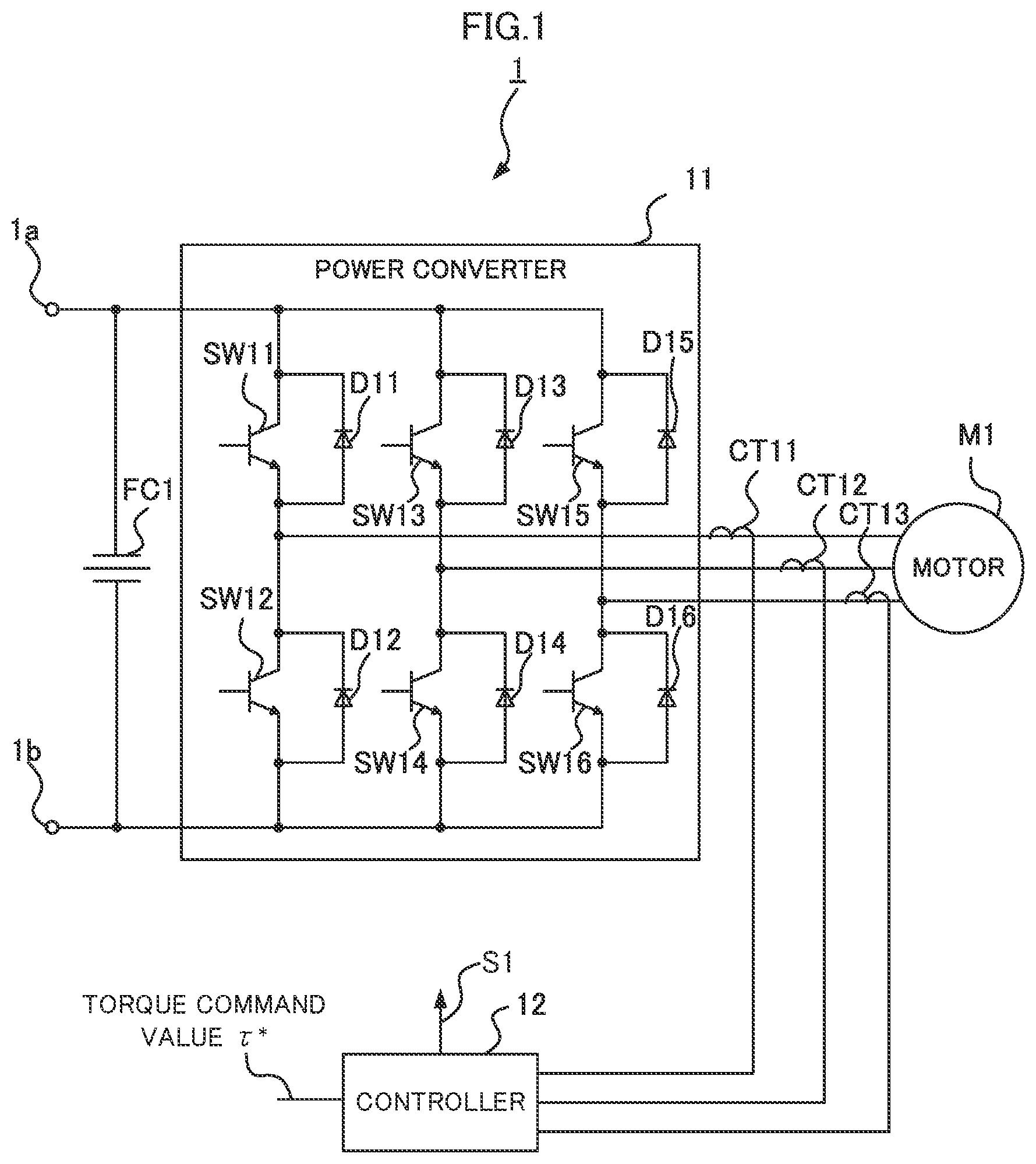
A drive system according to an embodiment of the present disclosure is described in detail below with reference to the accompanying drawings. In the drawings, the components identical or corresponding to each other are provided with the same reference symbol. The following description is directed to a drive system 1 according to an embodiment, focusing on an exemplary drive system for generating propulsive force of a railway vehicle. The drive system 1 illustrated in is installed under the floor of the railway vehicle, for example. The drive system 1 , for example, converts DC power into three-phase AC power, feeds the three-phase AC power to a motor, and thus drives the motor, thereby generating propulsive force of the railway vehicle. The drive system 1 includes a terminal 1 a connected to a power source, a terminal 1 b that is grounded, a filter capacitor FC 1 to be charged with DC power fed from the power source, and a power converter 11 , which is a DC/AC three-phase converter to convert the DC power fed from the power source via the filter capacitor FC 1 into three-phase AC power. The drive system 1 further includes a motor M 1 , which is a reluctance motor to rotate in response to feeding of the three-phase AC power from the power converter 11 , current sensors CT 11 , CT 12 , and CT 13 to measure values of phase currents flowing to the motor M 1 , and a controller 12 to control switching elements SW 11 , SW 12 , SW 13 , SW 14 , SW 15 , and SW 16 included in the power converter 11 . The power converter 11 is connected directly to the motor M 1 . This direct connection means the connection of components without an active element therebetween. Specifically, the power converter 11 is connected to the motor M 1 without a switching circuit therebetween, which serves to electrically disconnect the motor M 1 from the power converter 11 . Examples of the switching circuit include electromagnetic contactors, semiconductor switches, and mechanical switches to be manually operated. Since the power converter 11 is connected directly to the motor M 1 , the drive system 1 has a simpler structure than that of a drive system provided with a contactor between a power converter and a permanent-magnet synchronous motor. The individual components of the drive system 1 are described in detail below. The terminal 1 a is electrically connected to the power source, which is not illustrated. A typical example of the power source is a current collector to acquire electric power from a power supply line. The power supply line is an overhead wire or a third rail, for example. The current collector is a pantograph or a contact shoe, for example. The terminal 1 a is preferably electrically connected to the current collector via a device, such as contactor or filter reactor. The terminal 1 b is grounded via a wheel. The filter capacitor FC 1 has one end electrically connected to the terminal 1 a , and the other end electrically connected to the terminal 1 b . The filter capacitor FC 1 constitutes a filter together with the filter reactor, which is provided between the terminal 1 a and the current collector as described above, and thereby reduces harmonic components. The power converter 11 is an inverter to convert DC power into three-phase AC power, for example, an inverter capable of variable voltage variable frequency control. The power converter 11 according to the embodiment includes the switching elements SW 11 and SW 12 connected to a U-phase coil of the motor M 1 , the switching elements SW 13 and SW 14 connected to a V-phase coil of the motor M 1 , and the switching elements SW 15 and SW 16 connected to a W-phase coil of the motor M 1 . The power converter 11 also includes freewheeling diodes D 11 , D 12 , D 13 , D 14 , D 15 , and D 16 connected in parallel to the respective switching elements SW 11 , SW 12 , SW 13 , SW 14 , SW 15 , and SW 16 . The switching elements SW 11 and SW 12 are connected in series to each other, the switching elements SW 13 and SW 14 are connected in series to each other, and the switching elements SW 15 and SW 16 are connected in series to each other. The point of connection between the switching elements SW 11 and SW 12 is connected directly to the U-phase coil of the motor M 1 . The point of connection between the switching elements SW 13 and SW 14 is connected directly to the V-phase coil of the motor M 1 . The point of connection between the switching elements SW 15 and SW 16 is connected directly to the W-phase coil of the motor M 1 . The serially connected switching elements SW 11 and SW 12 , the serially connected switching elements SW 13 and SW 14 , and the serially connected switching elements SW 15 and SW 16 are connected in parallel to one another. The switching elements SW 11 , SW 12 , SW 13 , SW 14 , SW 15 , and SW 16 are switched between on and off states by the controller 12 . The power converter 11 thus converts the DC power fed from the power source via the filter capacitor FC 1 into three-phase AC power to be fed to the motor M 1 . The power converter 11 then feeds the three-phase AC power to the motor M 1 . For example, the switching elements SW 11 , SW 12 , SW 13 , SW 14 , SW 15 , and SW 16 are insulated gate bipolar transistors (IGBTs). The motor M 1 to be fed with the three-phase AC power from the power converter 11 is a reluctance motor, and thus has a low power factor and requires a reactive current. A conceivable solution is expansion of the volume of the power converter 11 , but the power converter 11 having an expanded volume inevitably has an increased size. In order to reduce the iron loss in the motor M 1 , the power converter 11 needs to execute high-frequency switching. In the case where the switching elements SW 11 , SW 12 , SW 13 , SW 14 , SW 15 , and SW 16 are semiconductor devices made of silicon, the high-frequency switching generates increased amounts of heat, and requires a larger cooling device for cooling the switching elements SW 11 , SW 12 , SW 13 , SW 14 , SW 15 , and SW 16 . Existing railway vehicles do not include reluctance motors because a vehicle control apparatus including a large power converter and a large cooling device cannot be readily installed in the limited space under the floor or on the roof of a railway vehicle. In this embodiment, wide-gap semiconductors are employed as the switching elements SW 11 , SW 12 , SW 13 , SW 14 , SW 15 , and SW 16 included in the power converter 11 . This configuration can achieve expansion of the volume of the power converter 11 and execution of high-frequency switching while maintaining the sufficiently small size of the power converter 11 , and allow a reluctance motor to be employed as the motor M 1 . The wide-gap semiconductors are made of a material, such as silicon carbide, gallium nitride material, or diamond, having a larger bandgap than silicon. The anodes of the freewheeling diodes D 11 , D 12 , D 13 , D 14 , D 15 , and D 16 are respectively connected to the emitters of the switching elements SW 11 , SW 12 , SW 13 , SW 14 , SW 15 , and SW 16 , and the cathodes are respectively connected to the collectors of the switching elements SW 11 , SW 12 , SW 13 , SW 14 , SW 15 , and SW 16 . This circuitry suppress an inverse current from flowing to the switching elements SW 11 , SW 12 , SW 13 , SW 14 , SW 15 , and SW 16 . The motor M 1 is a reluctance motor to rotate in response to feeding of three-phase AC power from the power converter 11 . The motor M 1 according to the embodiment is a synchronous reluctance motor including no permanent magnet. The motor M 1 lacks a permanent magnet and thus is free from a no-load induced voltage. This configuration therefore does not require a contactor between the power converter 11 and the motor M 1 for electrically disconnecting the motor M 1 from the power converter 11 in order to suppress a current from flowing from the motor M 1 to the power converter 11 when the power converter 11 stops. In other words, the configuration allows the power converter 11 to be connected directly to the motor M 1 . The current sensors CT 11 , CT 12 , and CT 13 measure values of phase currents flowing to the motor M 1 and output the measured current values to the controller 12 . For example, the current sensors CT 11 , CT 12 , and CT 13 are current transformer (CT) sensors. In detail, the current sensor CT 11 is provided to a bus bar that connects the point of connection between the switching elements SW 11 and SW 12 to the U-phase coil of the motor M 1 , and measures a value of U-phase current flowing from the power converter 11 to the motor M 1 . The current sensor CT 12 is provided to a bus bar that connects the point of connection between the switching elements SW 13 and SW 14 to the V-phase coil of the motor M 1 , and measures a value of V-phase current flowing from the power converter 11 to the motor M 1 . The current sensor CT 13 is provided to a bus bar that connects the point of connection between the switching elements SW 15 and SW 16 to the W-phase coil of the motor M 1 , and measures a value of W-phase current flowing from the power converter 11 to the motor M 1 . The controller 12 generates gate signals S 1 for controlling the switching elements SW 11 , SW 12 , SW 13 , SW 14 , SW 15 , and SW 16 , on the basis of a torque command value τ* in accordance with an operation at a master controller installed in a cab, which is not illustrated, of the railway vehicle, and the measured current values acquired from the current sensors CT 11 , CT 12 , and CT 13 . The controller 12 then outputs the generated gate signals S 1 . As illustrated in , the controller 12 includes a current command calculator 21 to calculate current command values from the torque command value τ*, a voltage command calculator 22 to calculate voltage command values from the current command values, and a rotating coordinate inverse transformer 23 to execute coordinate transformation of the voltage command values. The controller 12 further includes a position estimator 24 to estimate a position of the magnetic pole of the rotor included in the motor M 1 , a rotating coordinate transformer 25 to execute coordinate transformation of the measured current values, and a gate signal generator 26 to generate gate signals S 1 . The current command calculator 21 calculates current command values i* d and i* q in the rotating coordinate for achieving the target torque of the motor M 1 indicated by the torque command value τ*. For example, the current command values i* d and i* q provide the minimum current effective value relative to the torque, that is, the minimum copper loss of the motor M 1 . The voltage command calculator 22 calculates voltage command values v* d and v* q in the rotating coordinate, by obtaining the proportional integral of the differences (i* d −i d ) and (i* q −i q ) between the current command values i* d and i* q calculated by the current command calculator 21 and the measured current values i d and i q generated by the rotating coordinate transformer 25 . The rotating coordinate inverse transformer 23 converts the voltage command values v* d and v* q in the rotating coordinate into voltage command values v* α and v* β in the two-phase coordinate, on the basis of a transformation matrix containing an estimated position θ{circumflex over ( )}, that is, a position of the magnetic pole of the rotor included in the motor M 1 estimated by the position estimator 24 . The rotating coordinate inverse transformer 23 then converts the voltage command values v* α and v* β in the two-phase coordinate into voltage command values v* u , v* v , and v* w in the three-phase coordinate, on the basis of a two-phase/three-phase transformation matrix. The position estimator 24 estimates a position of the magnetic pole of the rotor included in the motor M 1 , on the basis of the measured current values i u , i v , and i w acquired from the current sensors CT 11 , CT 12 , and CT 13 , and the voltage command values v* u , v* v , and v* w in the three-phase coordinate calculated by the rotating coordinate inverse transformer 23 . The estimated position θ{circumflex over ( )}, that is, the position of the magnetic pole of the rotor estimated by the position estimator 24 is represented in terms of electrical angle. The rotating coordinate transformer 25 converts the measured current values i u , i v , and i w in the three-phase coordinate into measured current values i α and i β in the two-phase coordinate, on the basis of a three-phase/two-phase transformation matrix. The rotating coordinate transformer 25 then converts the measured current values i α and i β in the two-phase coordinate into measured current values i d and i q in the rotating coordinate, on the basis of a transformation matrix containing the estimated position θ{circumflex over ( )}. The gate signal generator 26 generates gate signals S 1 through pulse width modulation (PWM) control. In detail, as illustrated in , the gate signal generator 26 includes a modulated wave generator 31 to generate modulated waves in accordance with the voltage command values v* u , v* v , and v* w , a differentiator 32 to calculate a rotational speed ω{circumflex over ( )} of the motor M 1 through differentiation of the estimated position θ{circumflex over ( )}, a carrier wave generator 33 to generate a carrier wave in accordance with the rotational speed ω{circumflex over ( )} of the motor M 1 , and a comparator 34 to generate gate signals on the basis of comparison between the modulated waves and the carrier wave. The modulated wave generator 31 generates modulated waves on the basis of the voltage command values v* u , v* v , and v* w in the three-phase coordinate acquired from the rotating coordinate inverse transformer 23 . The modulated waves are signals obtained through standardization of the voltage command values v* u , v* v , and v* w using the value of the voltage between the terminals of the filter capacitor FC 1 . The differentiator 32 calculates a rotational speed ω{circumflex over ( )} of the motor M 1 through differentiation of the estimated position OA. The carrier wave generator 33 generates a carrier wave in accordance with the rotational speed ω{circumflex over ( )} of the motor M 1 calculated by the differentiator 32 . The frequency of the carrier wave increases in accordance with acceleration of the rotational speed of the motor M 1 . In other words, the frequency of the carrier wave has a positive correlation with the rotational speed of the motor M 1 . The carrier wave generator 33 according to the embodiment generates a carrier wave, which is a signal obtained by multiplying the frequency of the modulated waves. The operation mode of the gate signal generator 26 , in the case where the carrier wave is synchronized with the modulated waves and is a signal obtained by multiplying the frequency of the modulated waves, is defined as a synchronous multiple pulse mode. For example, when the gate signal generator 26 operates in the synchronous multiple pulse mode, the carrier wave generator 33 generates a carrier wave of which the frequency is 15 times higher than the frequency of the modulated waves. The comparator 34 generates gate signals S 1 on the basis of comparison between the modulated waves generated by the modulated wave generator 31 and the carrier wave generated by the carrier wave generator 33 , and outputs the generated gate signals S 1 to the switching elements SW 11 , SW 12 , SW 13 , SW 14 , SW 15 , and SW 16 . In detail, the gate signals S 1 for the switching elements SW 11 , SW 13 , and SW 15 are at a high (H) level when the value of the modulated waves is equal to or higher than the value of the carrier wave, and at a low (L) level when the value of the modulated waves is lower than the value of the carrier wave. The gate signals S 1 for the switching elements SW 12 , SW 14 , and SW 16 are at an L level when the value of the modulated waves is equal to or higher than the value of the carrier wave, and at an H level when the value of the modulated waves is lower than the value of the carrier wave. The switching elements SW 11 , SW 12 , SW 13 , SW 14 , SW 15 , and SW 16 are switched between on and off states in accordance with the gate signals S 1 output from the comparator 34 . The gate signal generator 26 operating in the synchronous multiple pulse mode can reduce the distortion of currents flowing to the motor M 1 and allow the motor M 1 to function with high efficiency. As described above, the motor M 1 included in the drive system 1 according to the embodiment is a synchronous reluctance motor including no permanent magnet and thus is free from a no-load induced voltage. The drive system 1 therefore does not require a contactor for electrically disconnecting the motor M 1 from the power converter 11 in the case of stop of the inverter due to a short-circuit fault in the inverter, for example, and allows the power converter 11 to be connected directly to the motor M 1 . The drive system 1 according to the embodiment does not need a contactor and thus has a simpler structure than that of a drive system provided with a contactor between a power converter and a motor. The above-described examples are not to be construed as limiting the present disclosure. The drive system 1 may include multiple power converters 11 and multiple motors M 1 . Because the power converters 11 and the motors M 1 need to be associated with each other on a one-to-one basis, the number of power converters 11 is equal to the number of motors M 1 in the drive system 1 . For example, illustrates a drive system 2 including two power converters 11 and 13 , two motors M 1 and M 2 , and two filter capacitors FC 1 and FC 2 to be charged with electric power fed from a power source, which is not illustrated. The power converters 11 and 13 have the identical configuration. The motors M 1 and M 2 have the identical configuration. The filter capacitors FC 1 and FC 2 have the identical configuration. The drive system 2 also includes current sensors CT 11 , CT 12 , and CT 13 to measure values of phase currents flowing to the motor M 1 , current sensors CT 21 , CT 22 , and CT 23 to measure values of phase currents flowing to the motor M 2 , and a controller 12 to control multiple switching elements included in each of the power converters 11 and 13 . The filter capacitors FC 1 and FC 2 are connected to the power source so as to be in parallel to each other. In detail, the filter capacitor FC 1 has one end connected to the terminal 1 a , and the other end connected to the terminal 1 b . The filter capacitor FC 2 has one end connected to the terminal 1 a , and the other end connected to the terminal 1 b . The filter capacitors FC 1 and FC 2 are charged with electric power fed from the power source. As in the above-described embodiment, the current sensors CT 11 , CT 12 , and CT 13 measure values of phase currents flowing to the motor M 1 and output the measured current values to the controller 12 . The current sensors CT 21 , CT 22 , and CT 23 measure values of phase currents flowing to the motor M 2 and output the measured current values to the controller 12 . The current sensors CT 21 , CT 22 , and CT 23 are provided to the respective bus bars that connect the power converter 13 to the motor M 2 , like the current sensors CT 11 , CT 12 , and CT 13 . The controller 12 generates gate signals S 1 for controlling the switching elements included in the power converter 11 , on the basis of a torque command value τ* indicating a target torque of the motor M 1 and the current values measured by the current sensors CT 11 , CT 12 , and CT 13 , and then outputs the generated gate signals S 1 , as in the above-described embodiment. The controller 12 also generates gate signals S 2 for controlling the switching elements included in the power converter 13 , on the basis of a torque command value τ* indicating a target torque of the motor M 2 and the current values measured by the current sensors CT 21 , CT 22 , and CT 23 , and then outputs the generated gate signals S 2 . The gate signals S 1 and S 2 are generated in the same manner as in the embodiment. In the drive system 2 including the motors M 1 and M 2 , the power converter 11 is connected directly to the motor M 1 , and the power converter 13 is connected directly to the motor M 2 . The drive system 2 therefore has a simpler structure than that of a drive system provided with contactors between power converters and motors. Although the drive system 2 includes the filter capacitors FC 1 and FC 2 of which the number is equal to the number of power converters 11 and 13 in the example illustrated in , the power converters 11 and 13 may also be connected to a single filter capacitor in common. illustrates a drive system 3 that includes a filter capacitor FC 1 alone. The drive system 3 differs from the drive system 2 in that the power converters 11 and 13 are connected to the filter capacitor FC 1 in common. The drive systems 1 to 3 do not necessarily include all of the current sensors CT 11 , CT 12 , and CT 13 and may include only two of the current sensors CT 11 , CT 12 , and CT 13 . For example, the drive systems 1 to 3 may cause the current sensors CT 11 and CT 12 to measure values of U-phase and V-phase currents flowing to the motor M 1 and calculate a value of W-phase current from the measured values of U-phase and V-phase currents. In this case, the controller 12 generates gate signals S 1 on the basis of the measured values of U-phase and V-phase currents and the calculated value of W-phase current. The drive systems 2 and 3 may include any number of power converters 11 and 13 and any number of motors M 1 and M 2 , provided that the number of power converters is equal to the number of motors. The drive systems 2 and 3 may include two controllers 12 independent from each other. In this case, one of the controllers 12 controls the power converter 11 , and the other controller 12 controls the power converter 13 . Although the direct connection means the connection of components without an active element therebetween in the above-described embodiment, the power converter 11 and the motor M 1 may also be connected to each other with none of an active element and a passive element therebetween. The same holds true for the connection between the power converter 13 and the motor M 2 . The scope of the direct connection between the power converter 11 and the motor M 1 encompasses the connections via a component, such as relay terminal or relay cable. In an exemplary case where the power converter 11 and the motor M 1 are installed in mutually different vehicle bodies, the power converter 11 and the motor M 1 are connected to each other via a relay terminal. The same holds true for the direct connection between the power converter 13 and the motor M 2 . The carrier wave and the modulated waves are not necessarily synchronized with each other. The mode, in the case where the carrier wave is not synchronized with the modulated waves and have a frequency higher than the frequency of the modulated waves, is defined as an asynchronous multiple pulse mode. The gate signal generator 26 operating in the asynchronous multiple pulse mode can reduce the distortion of currents flowing to the motor M 1 and allow the motor M 1 to function with high efficiency, as in the case of the synchronous multiple pulse mode. The frequency of the carrier wave may be equal to the frequency of the modulated waves in the case of a low rotational speed of the motor M 1 . The controller 12 may acquire a measured value from a position sensor for measuring a position of the magnetic pole of the rotor included in the motor M 1 , and generate gate signals S 1 in accordance with the value measured by the position sensor. In this case, the gate signal generator 26 lacks the position estimator 24 and generates gate signals S 1 in accordance with the value measured by the position sensor. The motor M 1 may also be a switched reluctance motor, for example, provided that the motor M 1 includes no permanent magnet. The switching elements SW 11 , SW 12 , SW 13 , SW 14 , SW 15 , and SW 16 may be semiconductor devices made of silicon, and the freewheeling diodes D 11 , D 12 , D 13 , D 14 , D 15 , and D 16 may be wide-gap semiconductors. The drive systems 1 to 3 are not necessarily installed under the floors of railway vehicles and may also be installed at any site. For example, the drive systems 1 to 3 may be installed on the roofs of railway vehicles. The drive systems 1 to 3 may be installed not only in railway vehicles of a DC feeding system but also in railway vehicles of an AC feeding system. Any of the drive systems 1 to 3 installed in a railway vehicle of an AC feeding system is fed with electric power, which is subject to voltage reduction at a transformer and conversion at a converter from AC power into DC power. The drive systems 1 to 3 may be installed in railway vehicles other than electric railway vehicles. For example, any of the drive systems 1 to 3 may be installed in a diesel vehicle and fed with electric power from a generator driven by an internal combustion engine to generate electric power. For another example, any of the drive systems 1 to 3 may be installed in a rechargeable battery vehicle and fed with electric power from a rechargeable battery. The drive systems 1 to 3 may be installed in any moving body, such as automobile, marine vessel, or aircraft, other than the railway vehicles. The foregoing describes some example embodiments for explanatory purposes. Although the foregoing discussion has presented specific embodiments, persons skilled in the art will recognize that changes may be made in form and detail without departing from the broader spirit and scope of the invention. Accordingly, the specification and drawings are to be regarded in an illustrative rather than a restrictive sense. This detailed description, therefore, is not to be taken in a limiting sense, and the scope of the invention is defined only by the included claims, along with the full range of equivalents to which such claims are entitled. REFERENCE SIGNS LIST 1 , 2 , 3 Drive system 1 a , 1 b Terminal 11 , 13 Power converter 12 Controller 21 Current command calculator 22 Voltage command calculator 23 Rotating coordinate inverse transformer 24 Position estimator Rotating coordinate transformer 26 Gate signal generator 31 Modulated wave generator 32 Differentiator 33 Carrier wave generator 34 Comparator CT 11 , CT 12 , CT 13 , CT 21 , CT 22 , CT 23 Current sensor D 11 , D 12 , D 13 , D 14 , D 15 , D 16 Freewheeling diode FC 1 , FC 2 Filter capacitor M 1 , M 2 Motor S 1 , S 2 Gate signal SW 11 , SW 12 , SW 13 , SW 14 , SW 15 , SW 16 Switching element
Figures (5)
Citations
This patent cites (21)
- US2017/0110999
- US2018/0236999
- US2019/0222158
- US2021/0270911
- US2002-199675
- US2008148377
- US2009227221
- US2010136537
- US2012075317
- US2016025742
- US2017-057077
- US2018-042321
- US2018042423
- US2018-057077
- US2018166349
- US2020-044949
- US2020-108232
- US2015/159694
- US2017/073144
- US2020/067304
- USWO-2020110315