Abstract
A curvature variable device includes a curvature variable substrate and a display layer disposed on the curvature variation substrate. The first average luminance is different from the second average luminance. The curvature variable device is configured to have a first average luminance when operated in a first display status, and is configured to have a second average luminance when operated in a second display status. The curvature variable device includes at least one curved portion when operated in the second display status.
Claims (11)
1 . A curvature variable device, comprising: a curvature variable substrate; and a display layer disposed on the curvature variation substrate, wherein the curvature variable device is configured to have a first average luminance when operated in a first display status, and is configured to have a second average luminance when operated in a second display status; wherein the curvature variable device comprises at least one curved portion when operated in the second display status, and the first average luminance is different from the second average luminance; wherein one of the first display status and the second display status is in an off state, and another of the first display status and the second display status is in an on state; and wherein in the off state, the curvature variable device displays no image.
Show 10 dependent claims
2 . The curvature variable device of claim 1 , wherein the curvature variable substrate comprises at least one curved portion when the curvature variable device is operated in the second display status.
3 . The curvature variable device of claim 1 , wherein when the curvature variable device is operated in the first display status, the display layer has a first area, when the curvature variable device is operated in the second display status, the display layer has a second area, and the first area is different from the second area.
4 . The curvature variable device of claim 3 , wherein a length-width ratio of the first area is different from a length-width ratio of the second area.
5 . The curvature variable device of claim 1 , wherein the display layer comprises a plurality of subpixel units, and at least one of the plurality of subpixel units comprises a light emitting element.
6 . The curvature variable device of claim 5 , wherein the at least one of the plurality of subpixel units comprises a switching element electrically connected to the light emitting element.
7 . The curvature variable device of claim 1 , wherein the display layer comprises a first region and a second region, a distance between the first region and a user is different from a distance between the second region and the user, and an average luminance of the first region is different from an average luminance of the second region.
8 . The curvature variable device of claim 5 , wherein the plurality of subpixel units comprises a first subpixel unit and a second subpixel unit disposed adjacent to the first subpixel unit, when the curvature variable device is operated in the first display status, a first distance is between the first subpixel unit and the second subpixel unit, when the curvature variable device is operated in the second display status, a second distance is between the first subpixel unit and the second subpixel unit, and the first distance is different from the second distance.
9 . The curvature variable device of claim 8 , wherein the curvature variable device is capable of being switchable between the first display status and the second display status.
10 . The curvature variable device of claim 1 , wherein the curvature variable device has an edge region and a middle region, the display layer comprises a plurality of subpixel units, the display layer has a first area in the first display status, the display layer has a second area in the second display status, and the second area is greater than the first area, wherein when the curvature variable device is operated in the first display status, a distance between two adjacent ones of the subpixel units in the edge region is equal to a distance between two adjacent ones of the subpixel units in the middle region, and when the curvature variable device is operated in the second display status, the distance between the two adjacent ones of the subpixel units in the edge region is different from the distance between the two adjacent ones of the subpixel units in the middle region.
11 . The curvature variable device of claim 1 , wherein the curvature variable device is capable of being switchable between the first display status and the second display status.
Full Description
Show full text →
CROSS REFERENCE TO RELATED APPLICATIONS
This application is a continuation application of U.S. application Ser. No. 17/231,024, filed on Apr. 15, 2021, which is a division of U.S. application Ser. No. 16/293,597, filed on Mar. 5, 2019. The contents of these applications are incorporated herein by reference.
BACKGROUND
OF THE DISCLOSURE 1. Field of the Disclosure The present disclosure is related to a stretchable display device and related controlling method, and more particularly, to a stretchable display device that the average luminance can be adjusted and related controlling method. 2. Description of the Prior Art In recent years, display devices have become more and more important for being applied to various applications, such as smartphones, tablet computers, notebooks, and electronic book readers, and wearable devices, such as smart watches. The manufacturers still keep on developing new types of display devices.
SUMMARY
OF THE DISCLOSURE One of the objectives of the present disclosure is to provide a stretchable display device and related controlling method with a good perception of human eyes. According to an embodiment, a curvature variable device is provided. The curvature variable device includes a curvature variable substrate and a display layer disposed on the curvature variation substrate. The first average luminance is different from the second average luminance. The curvature variable device is configured to have a first average luminance when operated in a first display status, and is configured to have a second average luminance when operated in a second display status. The curvature variable device includes at least one curved portion when operated in the second display status. According to an embodiment, a stretchable display device is provided. The stretchable display device includes: a stretchable substrate and a display layer disposed on the stretchable substrate. The display layer is capable of being stretched from a first area to a second area. The stretchable display device has a first average luminance when the display layer has the first area and a second average luminance when the display layer has the second area. The second average luminance is greater than the first average luminance. According to an embodiment, a method of controlling a stretchable display device is provided. The stretchable display device includes a stretchable substrate and a display layer disposed thereon, and the display layer having a first area when the stretchable substrate is not stretched. The method includes the following steps: providing a first predetermined limit value; providing a second area of the display layer when the stretchable substrate is stretched; providing a stretching ratio from the first area and the second area; providing a first display status of the stretchable display device when the stretching ratio is less than the first predetermined limit value; and providing a second display status of the stretchable display device when the stretching ratio is equal to or greater than the first predetermined limit value, wherein the first display status is different from the second display status. These and other objectives of the present disclosure will no doubt become obvious to those of ordinary skill in the art after reading the following detailed description of the embodiment that is illustrated in the various figures and drawings.
BRIEF DESCRIPTION OF THE DRAWINGS
is a schematic diagram illustrating different display statuses of a stretchable display device according to a first embodiment of the present disclosure. is a schematic sectional-view diagram of different display statuses of the stretchable display device shown in . is a schematic top-view diagram showing pixel units of a stretchable display according to a variant embodiment of the first embodiment of the present disclosure. is a schematic top-view diagram showing pixel units of a stretchable display according to another variant embodiment of the first embodiment of the present disclosure. is a schematic diagram illustrating different display statuses of a stretchable display device according to a second embodiment of the present disclosure is a schematic sectional-view diagram of the stretchable display device in a second display status according to a third embodiment of the present disclosure. is a schematic diagram illustrating different display statuses of a stretchable display device according to a fourth embodiment of the present disclosure. is a schematic diagram illustrating different display statuses of a stretchable display device according to a fifth embodiment of the present disclosure. is a schematic diagram illustrating different display modes of a stretchable display device according to a sixth embodiment of the present disclosure. is a schematic diagram illustrating different display statuses of a stretchable display device according to a seventh embodiment of the present disclosure. is a flow chart showing a method of controlling the stretchable display device according to the first embodiment of the present disclosure. is a flow chart showing a method of controlling the stretchable display device according to a variant embodiment of the first embodiment of the present disclosure. is a flow chart showing a method of controlling the stretchable display device according to an eighth embodiment of the present disclosure. is a schematic diagram illustrating different display statuses of the stretchable display device according to the eighth embodiment of the present disclosure. is a flow chart showing a method of controlling the stretchable display device according to a ninth embodiment of the present disclosure.
DETAILED DESCRIPTION
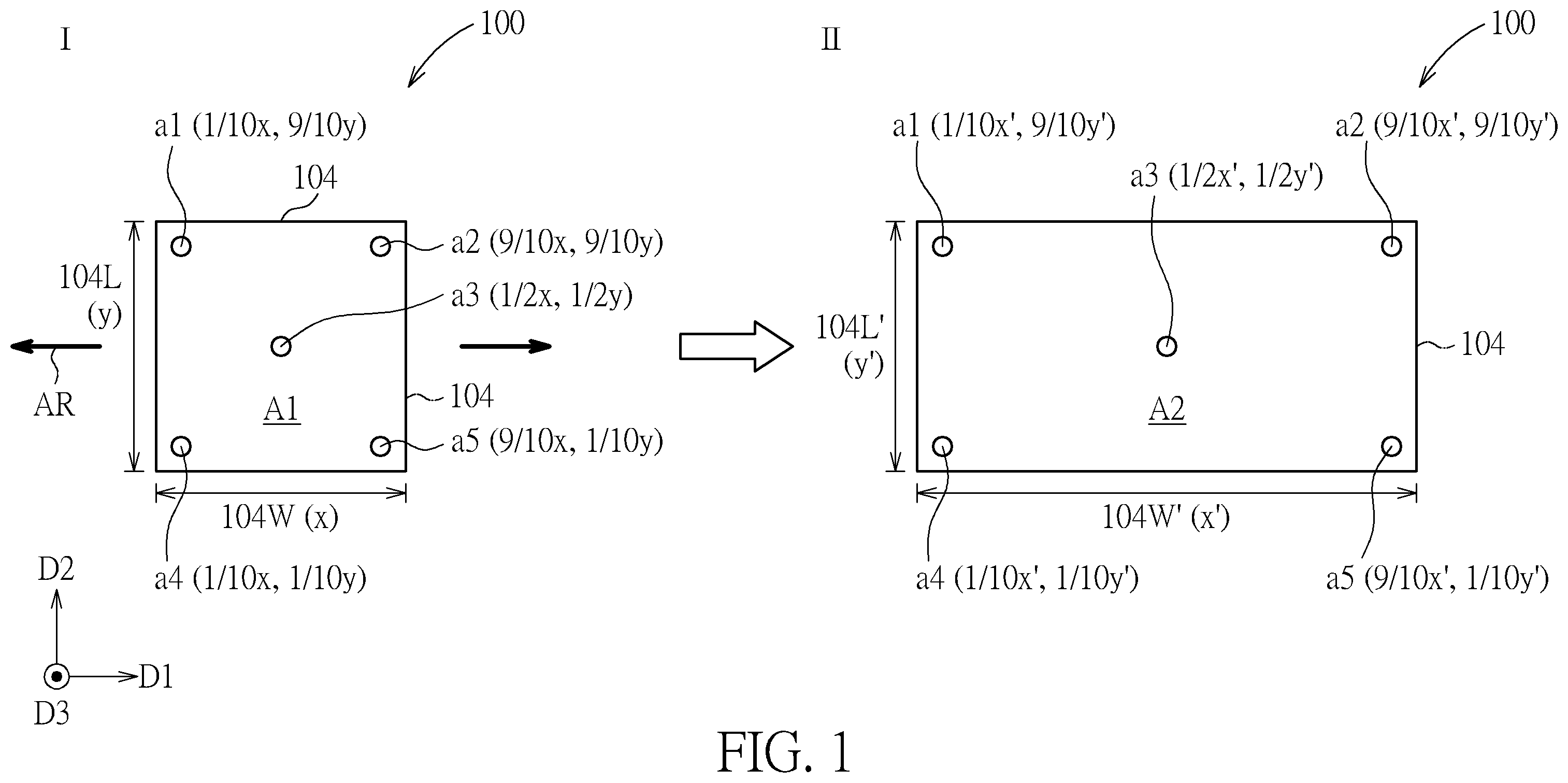
The present disclosure may be understood by reference to the following detailed description, taken in conjunction with the drawings as described below. It is noted that, for purposes of illustrative clarity and being easily understood by the readers, various drawings of this disclosure show a portion of the display device, and certain elements in various drawings may not be drawn to scale. In addition, the number and dimension of each device shown in drawings are only illustrative and are not intended to limit the scope of the present disclosure. Certain terms are used throughout the description and following claims to refer to particular components. As one skilled in the art will understand, electronic equipment manufacturers may refer to a component by different names. This document does not intend to distinguish between components that differ in name but not function. In the following description and in the claims, the terms “include”, “comprise” and “have” are used in an open-ended fashion, and thus should be interpreted to mean “include, but not limited to . . . ”. It will be understood that when an element or layer is referred to as being “on” or “connected to” another element or layer, it can be directly on or directly connected to the other element or layer, or intervening elements or layers may be presented. In contrast, when an element is referred to as being “directly on” or “directly connected to” another element or layer, there are no intervening elements or layers presented. The term “stretching/stretchable” in the present disclosure indicates that an object can be deformed when an external stress and/or force is applied thereto, and the deformation may include the variation of area, length, width, thickness, and/or curvature in any direction of the object, but not limited thereto. For example, an enlargement of the length of the object and/or a reduction of the length of the object may belong to the term “stretching/stretchable” mentioned in the present disclosure. It should be noted that the technical features in different embodiments described in the following can be replaced, recombined, or mixed with one another to constitute another embodiment without departing from the spirit of the present disclosure. Referring to and , is a schematic diagram illustrating different display statuses of a stretchable display device according to a first embodiment of the present disclosure, and is a schematic sectional-view diagram of different display statuses of the stretchable display device shown in . The stretchable display device 100 of the first embodiment of the present disclosure includes a stretchable substrate 102 and a display layer 104 . The display layer 104 may be disposed on the stretchable substrate 102 and may include a plurality of subpixel units 108 , wires, electrodes, switch elements and/or driving elements, but not limited thereto. For example, the subpixel units 108 may include any electric elements that can produce light, such as the primary lights (red light, blue light, and green light), for display images. In some embodiments, one subpixel unit 108 may include one or more light emitting units LEU and one or more switching element STE electrically connected to the light emitting unit LEU. The display layer 104 can be stretched from a first area A 1 to a second area A 2 . The second area A 2 can be greater than the first area A 1 , or can be smaller than the first area A 1 . For easy explanation, the situation that the second area A 2 is greater than the first area A 1 is taken as an example in the following embodiments. A ratio of the second area A 2 to the first area A 1 may be greater than 1 and less than or equal to 25, but not limited thereto. The light emitting unit LEU may be a light emitting diode (LED), a mini LED, a micro LED, or an organic LED, or any other suitable elements. In some embodiments, the size of a mini-LED can be in a range from 100 μm to 300 μm. In some embodiments, the size of a micro-LED can be in a range from 1 μm to 100 μm. The switching element STE may be a thin film transistor, but not limited thereto. In some embodiments, when a display datum of the display layer 104 is changed by stretching, the stretchable display device can be operated by a different display status. The display datum can comprise, but not limited to, dimension, dimension change, dimension ratio, ratio of dimension change, curvature, curvature change, curvature ratio, ratio of curvature change, stretching ratio, shape, or combinations thereof. For example, the dimension can be area, width, length, or combination thereof, but not limited thereto. For example, dimension ratio can refer to length-width ratio. The display status can include luminance, displayed image, display mode, turned-on/turned-off state, display shape of the image, display information, or combinations thereof, but not limited thereto. In some embodiments, when the display layer 104 has the first area A 1 , it is operated in a first display status I; and when the display layer 104 has the second area A 2 , it is operated in a second display status II, wherein the area of the display layer 104 may indicate the display datum that may regard the display status in the control method of the stretchable display device 100 as mentioned above). The first display status I is different from the second display status II. For example, in some embodiments, the stretchable display device 100 is in an off state when the display layer 104 has the first area A 1 and is in an on state when the display layer 104 has the second area A 2 , but not limited thereto. The “off state” means the display function of the stretchable display device 100 is in a turned-off state, and the “on state” means the display function of the stretchable display device 100 is in a turned-on state. The stretchable display device 100 may be stretched along various directions, thus the display layer 104 can stretch toward various directions and the dimensions of the display layer 104 may be changed. In detail, the display layer 104 of the stretchable display device 100 can have a width along a direction D 1 , a length along a direction D 2 , and a thickness along a direction D 3 , shown in . The direction D 1 crosses the direction D 2 . For example, the direction D 1 is perpendicular to the direction D 2 , and perpendicular to the direction D 3 . When the stretchable display device 100 is not stretched and the display layer 104 has the first area A 1 (in the first display status I), the display layer 104 has a width 104 W and a length 104 L. In some embodiments, as shown in , the stretchable display device 100 can be stretched along a horizontal direction (as illustrated as the arrows AR), such as, but not limited to, parallel to the direction D 1 , and therefore the stretched display layer 104 having the second area A 2 (in the second display status II) may have a stretched width 104 W′ greater than the width 104 W and a stretched length 104 L′ approximately equal to the length 104 L. In such case, the length-width ratio (a ratio of the length to the width of the area) of the first area A 1 is different from the length-width ratio of the second area A 2 . In some embodiments, the length-width ratio of the first area A 1 may be greater than the length-width ratio of the second area A 2 . As a result, the shape of the first area A 1 is different from the second area A 2 . When the stretchable display device 100 is stretched along multiple directions, multiple dimensions of the display layer 104 may be changed. Referring to again, the light emitting units LEU may be a flip-type micro-LED for example. One light emitting unit LEU may include a first electrode 150 , a second electrode 152 , a first semiconductor layer 154 , a light emitting layer 156 , and a second semiconductor layer 158 . The light emitting layer 156 may be, but not limited to, a multiple quantum well (MQW) layer for example. The first electrode 150 may be electrically connected to a common electrode through a bonding pad 162 . In addition, when the switching element STE is a thin film transistor, it may include a gate GE, a source SE, a drain DE, and a semiconductor layer SC, wherein the source SE and the drain DE are electrically connected to the semiconductor layer SC respectively and an insulating layer IN is positioned between the gate GE and the semiconductor layer SC. The source SE may be electrically connected to a signal line for example. The drain DE may be electrically connected to a bonding pad 160 or a connecting layer that is electrically connected to the corresponding light emitting unit LEU. The stretchable display device 100 may further include a functional layer 106 covering the display layer 104 . The functional layer 106 may include a touch layer, a cover layer, an anti-refection layer, a protection layer 106 - 1 , or combinations thereof. The stretchable display device 100 may include a plurality of gaps 114 disposed in the display layer 104 . In some embodiments, the stretchable display device 100 may further include a filler 120 disposed in the gaps 114 . The filler 120 can be inorganic insulating material, organic insulating material, or combinations thereof. In some embodiments, the filler 120 can be elastic material or adhesive material. According to the present disclosure, the stretchable display device 100 has a first average luminance AL 1 when the display layer has the first area A 1 and has a second average luminance AL 2 when the display layer 104 has the second area A 2 , and the second average luminance AL 2 is different from the first average luminance AL 1 . In some embodiments, the second average luminance AL 2 is greater than the first average luminance AL 1 . The average luminance may be obtained by calculating the average value of the measured luminance of, not limited to, five dots of the stretchable display device 100 . For example, the dots a 1 , a 2 , a 3 , a 4 , a 5 are selected for detecting the luminance. The coordinates of these fives dots are: a 1 =(1/10x, 9/10y), a 2 =(9/10x, 9/10y), a 3 =(1/2x, 1/2y), a 4 =(1/10x, 1/10y), and a 5 =(9/10x, 1/10y). Before the stretchable display 100 being stretched (i.e., the stretchable display 100 is in the first display status I with the first area A 1 ), the luminance of the five dots, a 1 (1/10x, 9/10y), a 2 (9/10x, 9/10y), a 3 (1/2x, 1/2y), a 4 (1/10x, 1/10y), and a 5 (9/10x, 1/10y) are measured and the average value thereof are calculated to obtain the first average luminance AL 1 . After the stretchable display device 100 is stretched to the second area A 2 , which means the stretchable display device 100 is in the second display status II, the five dots may become: a 1 =(1/10x′, 9/10y′), a 2 =(9/10x′, 9/10y′), a 3 =(1/2x′, 1/2y′), a 4 =(1/10x′, 1/10y′), and a 5 =(9/10x′, 1/10y), and the luminance of these dots may be measured and the average value is calculated to obtain the second average luminance AL 2 . As mentioned above, the second average luminance AL 2 may be greater than the first average luminance AL 1 in some embodiments. For example, when the stretchable display device 100 is in the second display status II, more current may be provided to the subpixel units 108 , thus the second average luminance AL 2 can be greater, but not limited thereto. The average luminance can be adjusted based on the area of the display layer 104 in order to maintain the perception luminance of human eyes or to provide different functions of the stretchable display device 100 , for example providing different luminance based on different requirement of different display statuses, but not limited thereto. The variation of average luminance between the first display status and the second display status may be applied to other embodiments and variant embodiments in the following, which will not be repeated. Referring to , when the stretchable display device 100 is stretched from having the first display datum (such as having a first area A 1 ) to having the second display datum (such as having the second area A 2 ), which means the display status of the stretchable display device 100 may be changed from the first display status I to the second display status II, the distance (or pitch) between the adjacent subpixel units 108 may be also stretched. In the first display status I, the distance between adjacent subpixel units 108 is represented as W 1 , wherein the distance W 1 is measured from a center of a light emitting unit LEU to a center of another adjacent light emitting unit LEU. After the stretchable display device 100 is stretched to the second display status II, the adjacent light emitting units LEU have a stretched distance W 1 ′ therebetween, and the stretched distance W 1 ′ is greater than the distance W 1 . Further, the gap 114 between adjacent subpixel units 108 may also be widened after stretching. Referring to , is a schematic top-view diagram showing pixel units of a stretchable display according to a variant embodiment of the first embodiment of the present disclosure. The display layer 104 of the stretchable display device 100 in this variant embodiment is capable of being stretched from a first width 104 W to a second width 104 W′ along a first direction D 1 . The stretchable display device 100 may have at least an edge region Ra and a middle region Rb disposed along the first direction D 1 . The edge region Ra is near a fringe 1041 of the display layer 104 . The middle region Rb is a region passed through by a central line 112 of the display layer 104 . In , two edge regions Ra are illustrated and the middle region Rb is situated between the two edge regions Ra in the first direction D 1 . The display layer 104 comprises a plurality of first subpixel units 108 a in the edge regions Ra and a plurality of second subpixel units 108 b in the middle region Rb. In other words, the first subpixel units 108 a in the left edge region Ra are closer to the fringe 1041 than the second subpixel units 108 b , and the second subpixel units 108 b are closer to the central line 112 than the first subpixel units 108 a . Before the stretchable display device 100 is stretched or when the stretchable display device 100 has the first area A 1 , two of the first subpixels 108 a adjacent to each other have a first distance PL 1 , and two of the second subpixels 108 b adjacent to each other have a second distance PL 2 . The first distance PL 1 may be the same as the second distance PL 2 in some embodiments, but not limited thereto. The first distance PL 1 may not be equal to the second distance PL 2 in some other embodiments. In some other embodiments, the ratio of the second distance PL 2 to the first distance PL 1 may be in a range from 0.95 to 1.05. When the display layer 104 is stretched to have the second area A 2 , one of the plurality of first subpixel units 108 a has a first stretched distance PL 1 ′ from an adjacent first subpixel unit 108 a , one of the plurality of second subpixel units 108 b has a second stretched distance PL 2 ′ from an adjacent second subpixel unit 108 b , and the first stretched distance PL 1 ′ may be the same as or different from the second stretched distance PL 2 ′. The ratio of the second stretched distance PL 2 ′ to the first stretched distance PL 1 ′ may be in a range from 0.7 to 1. As shown in , the above-mentioned ratio may be 1, which means the first stretched distance PL 1 ′ may be the same as the second stretched distance PL 2 ′. In another aspect, the variations of distances between adjacent subpixel units 108 may be different after stretching, based on their position. is a schematic top-view diagram showing pixel units of a stretchable display according to another variant embodiment of the first embodiment of the present disclosure. Referring to , before the stretchable display device 100 is stretched or when the stretchable display device 100 has the first area A 1 , one of the first subpixel units 108 a in the edge region Ra may have a first distance PL 1 from an adjacent subpixel unit 108 a in the edge region Ra, and one of the subpixel units 108 b in the middle region Rb may have a second distance PL 2 from an adjacent subpixel unit 108 b . When the stretchable display device 100 is stretched to have the second area A 2 and in the second display status II, the distance of the subpixel units 108 a in the edge region Ra and the adjacent subpixel unit 108 a may become the first stretched distance PL 1 ′, and the distance of the subpixel units 108 b in the middle region Rb may become the second stretched distance PL 2 ′. In some embodiments, the first stretched distance PL 1 ′ may be greater than the first distance PL 1 , and the second stretched distance PL 2 ′ may be greater than the second distance PL 2 . In addition, the first stretched distance PL 1 ′ may be greater than the second stretched distance PL 2 ′, but not limited thereto. In some embodiments, the ratio of the second stretched distance PL 2 ′ to the first stretched distance PL 1 ′ may be in a range from 0.7 to 1, but not limited thereto. This designed range of ratio of the distances may provide a better uniformity of the arrangement of the subpixel units 108 , mitigating that the display performance being affected after the stretchable display device 100 is stretched. Furthermore, a pixel (or subpixel) per inch of the first area A 1 is different from a pixel (or subpixel) per inch of the second area A 2 . Referring to , is a flow chart showing a method of controlling the stretchable display device 100 according to the first embodiment of the present disclosure. The stretchable display device 100 has a stretchable substrate 102 and a display layer 104 disposed thereon. The display layer 104 has a first area A 1 when the stretchable substrate 102 is not stretched. The method may include following steps: Step S 200 : Providing a first predetermined limit value PER 1 . Step S 202 : Providing a second area A 2 of the display layer 104 when the stretchable substrate 102 is stretched, wherein the absolute value of the difference between the first area A 1 and the second area A 2 is defined as an area difference ΔA (ΔA=|A 2 −A 1 |), i.e., the area difference ΔA is the “absolute difference” of the first area A 1 and the second area A 2 . Step S 204 : Providing a stretching ratio ER from the first area A 1 and the second area A 2 , wherein the stretching ratio ER is a ratio of the area difference ΔA to the first area A 1 (ER=ΔA/A 1 ). Step S 206 : Providing a first display status I of the stretchable display device 100 when the stretching ratio ER is less than the first predetermined limit value PER 1 (ER<PER 1 ). Step S 208 : Providing a second display status II of the stretchable display device 100 when the stretching ratio ER is equal to or greater than the first predetermined limit value PER 1 (ER≥PER 1 ), wherein the first display status I is different from the second display status II and the stretching ratio ER is calculated from the absolute difference of the first area A 1 and the second area A 2 . In some embodiments, the first predetermined limit value may be, but not limited to, in a range from 0.01 to 1. For example, if the first predetermined limit value is, but not limited to, 1 , the stretchable display device 100 will be switched to the second display status II when the second area A 2 is twice as large as the first area A 1 . In other words, once the stretchable display device 100 is stretched to a twice area, the stretchable display device 100 will be switched to the second display status II. In another example, if the first predetermined limit value PER 1 is, but not limited to, 0 . 5 , the stretchable display device 100 will be maintained in the first display status I when the stretching ratio ER<0.5 and will be in the second display status II when the stretching ratio ER≥ 0 . 5 . In some embodiments, the first display status I may be an off state and the second display status II may be an on state. Referring to , is a flow chart showing a method of controlling the stretchable display device 100 according to a variant embodiment of the first embodiment of the present disclosure. The method may include following steps: Step S 300 : Providing a first predetermined limit value PA 1 . For example, the first predetermined limit value PA 1 may correspond to a value of area, but not limited thereto. Step S 302 : Sensing a display datum A (such as the display area, the second area A 2 ) of the display layer 104 . Step S 304 : Comparing the display datum A and the first predetermined limit value PA 1 . Step S 306 : Providing a first display status I of the stretchable display device 100 when the display datum A is less than the first predetermined limit value PA 1 (A<PA 1 ). Step S 308 : Providing a second display status II of the stretchable display device 100 when the display datum A is equal to or greater than the first predetermined limit value PA 1 (A≥PA 1 ), wherein the first display status I is different from the second display status II. Accordingly, the stretchable display device 100 will be maintained in the first display status I until it is stretched to reach that condition that the display datum A is greater than or equal to the predetermined limit value PA 1 . The stretchable display device and method of controlling the stretchable display device of the present disclosure are not limited by the aforementioned embodiment, and may have other different embodiments and variant embodiments. To simplify the description, the identical components in each of the following embodiments are marked with identical symbols. For making it easier to compare the difference between the embodiments, the following description will detail the dissimilarities among different embodiments and the identical features will not be redundantly described. In addition, the material and thickness of each film or layer and related fabrication process or conditions of the present disclosure may refer to the first embodiment and related variant embodiment, which will not be repeated. Referring to , is a schematic diagram illustrating different display statuses of a stretchable display device according to a second embodiment of the present disclosure. In some embodiments, the stretchable display device 100 may be stretched along two directions, as shown in the arrows AR 1 and AR 2 , thus both the width 104 W and the length 104 L may be enlarged after stretching. When the display layer 104 of the stretchable display device 100 have the first area A 1 , the stretchable display device 100 is operated in the first display status I; when the display layer 104 of the stretchable display device 100 is stretched to have the second area A 2 , the stretchable display device 100 is operated in the second display status II. The stretched width 104 W′ in the second display status II is greater than the width 104 W in the first display status I and the stretched length 104 L′ in the second display status II is greater than the length 104 L in the first display status I. Furthermore, the distance between adjacent subpixel units 108 a / 108 b may be greater in both the direction D 1 and the direction D 2 . For example, in the direction D 1 , the first stretched distance PL 1 ′ and the second stretched distance PL 2 ′ of the second display status II may be greater than the first distance PL 1 and the second distance PL 2 of the first display status I. In the direction D 2 , two adjacent subpixel units 108 a or 108 b may have a third distance PL 3 when the stretchable display device 100 is in the first display status I, and the same two adjacent subpixel units 108 a or 108 b may have a third stretched distance PL 3 ′ when the stretchable display device 100 is in the second display status II. After stretching, the third stretched distance PL 3 ′ may be greater than the third distance PL 3 . In some embodiments, the shape of the display layer 104 after stretching (meaning the shape of the second area A 2 ) may be similar to the shape of the display layer 104 before stretching (meaning the shape of the first area A 1 ), but not limited thereto. In some other embodiments, the shape of the second area A 2 may be different from the shape of the first area A 1 . For example, the second area A 2 may be any other shapes, such as trapezoid or regular or irregular polygons or geometric shapes. Referring to , is a schematic sectional-view diagram of the stretchable display device in a second display status according to a third embodiment of the present disclosure, wherein the stretchable display device is operated in the second display status. In some embodiments, the stretchable display device 100 may be stretched along multiple directions (such as 3 directions). For example, the stretchable display device 100 may be stretched along the edges of the display layer 104 and also along a direction perpendicular to the surface of the stretchable substrate 102 . After stretching, the stretchable display device 100 may become a curved display device that has at least one curved portion. In some embodiments, since the stretchable display device 100 in the second display status II may be curved after stretching, the luminance of the subpixel units 108 in different regions of the display layer 104 may be adjusted in order to provide a better display performance or better display mode for the user. For example, the user eye 116 may be detected by the stretchable display device 100 to determine which subpixel units 108 are closer to the user eye 116 and which subpixel units 108 are farther from the user eye 116 . In , the subpixel unit 108 in the region R 1 is farther from the user eye 116 , and the subpixel units 108 in the region R 2 are closer to the user eye 116 . Therefore, the light emitting unit LEU 1 of the subpixel unit 108 in the region R 1 may have a luminance greater than the luminance of the light emitting units LEU 2 and LEU 3 of the subpixel units 108 in the region R 2 . In some embodiments, the luminance of the light emitting units LEU 1 , LEU 2 , LEU 3 may be adjusted based on whether they are positioned in a curved portion. In some embodiments, the luminance of the light emitting units LEU 1 , LEU 2 , LEU 3 may be adjusted based on whether the normal line of the portion of the stretchable substrate 102 where they are disposed directs toward the user eye 116 . In some embodiments, the luminance of the light emitting units LEU 1 , LEU 2 , LEU 3 may be adjusted based on whether their light emitting surfaces face the user eye 116 . From the above, the luminance of different light emitting units LEU 1 , LEU 2 , LEU 3 or different subpixel units 108 may be independent and may not be complete identical. The luminance of different light emitting units LEU 1 , LEU 2 , LEU 3 or different subpixel units 108 may be modified or adjusted according to different requirements or display statuses. Referring to , is a schematic diagram illustrating different display statuses of a stretchable display device according to a fourth embodiment of the present disclosure. According to some embodiments, in addition to a plurality of subpixel units 108 , the display layer 104 further includes a plurality of assistant subpixel units 108 S. When the stretchable display device 100 is in a first display status I, i.e., the display layer 104 has a first area A 1 , the subpixel units 108 are effective (such as in a turned-on state), but the assistant subpixel units 108 S are non-effective (such as in a turned-off state). After the display layer 104 is stretched to have a second area A 2 and the stretchable display device 100 is switched to the second display status II, the assistant subpixel units 108 S will be effective (marked by the symbol “ 108 S′”). For example, the effective assistant subpixel units 108 S′ may be turned on in the second display status II. In such design, a second average luminance AL 2 of the second display status II can be equal to or greater than the first average luminance AL 1 in the first display status I. For example, the second average luminance AL 2 may be greater than the first average luminance. The disposition of the assistant subpixel units 108 S/ 108 S′ may adjust the average luminance of the stretchable display device 100 . For instance, the average luminance can be adjusted to reduce the deviation of the luminance perception of human eyes between the first display status I and the second display status II. In addition, the PPI value of the first display status I (represented by PPI 1 ) may be different form the PPI value of the second display status II (represented by PPI 2 ) in some embodiments. For example, PPI 1 may be greater than PPI 2 , but not limited thereto. In some embodiments, the PPI 2 /PPI 1 value may be greater than 0.5 and less than 1. Such design can maintain a less PPI variation between the first display status I and the second display status II. In another aspect, the stretchable display device 100 can be stretched along at least two directions, such as along the direction D 1 and the direction D 2 . After being stretched, both the stretched length 104 L′ and the stretched width 104 W′ of the second area A 2 may be greater than the un-stretched length 104 L and the un-stretched width 104 W of the first area A 1 in the first display status I, but not limited thereto. Referring to , is a schematic diagram illustrating different display statuses of a stretchable display device according to a fifth embodiment of the present disclosure. In some embodiments, the stretchable display device 100 may be designed to have a property that when the display layer 104 is enlarged along a direction, the display layer 104 will shrink in another direction. As an exemplary embodiment shown in , in the first display status I, the display layer 104 has a first area A 1 with a width 104 W in the direction D 1 and a length 104 L in the direction D 2 . When the display layer 104 is stretched and the width of the display layer 104 along the direction D 1 is enlarged from the width 104 W to the enlarged width 104 W′, the length will be shrunk from the length 104 L to the shrunk length 104 L′ in the direction D 2 . In some embodiments, the variation of the length and width of the display layer 104 may meet, but not limited to, the following equations: 104 W ′ = 104 W + Δ W ; 104 L ′ = 104 L - Δ L ; and Δ L = Δ W . This design may provide a protection mechanism to the stretchable substrate 102 , such as to prevent the stretchable substrate 102 being over stretched (over enlarged or over shrunk) in different directions at the same time and/or mitigating the damage of the stretchable substrate 102 resulted from great stress variation when being stretched. Referring to , is a schematic diagram illustrating different display modes of a stretchable display device according to a sixth embodiment of the present disclosure. In some embodiments, the stretchable display device 100 may be stretched to have a second area A 2 with an irregular geometric shape or an irregular polygon rather than rectangular. In the second display status II, the stretchable display device 100 may have two or more display modes. As shown in the part (a) of , a first mode is illustrated that the image is full-screen displayed in a first display area AM 1 that occupies the whole display region (the second area A 2 of the display layer 104 ). In the part (b) of , a second mode is illustrated that the image is displayed in a rectangular display region, which is a second display area AM 2 and smaller than the whole second area A 2 . The stretchable display device 100 may figure out a preferred display area for displaying the image according to the provided image data. For example, when the image has irregular shape, it can be displayed in the first display mode; when the image has a rectangular shape, the largest rectangular display area may be figured out for display the rectangular image based on a predetermined algorithm, but not limited thereto. Referring to , is a schematic diagram illustrating different display statuses of a stretchable display device according to a seventh embodiment of the present disclosure. In some embodiments, the first status I and the second status II of the stretchable display device 100 may display non-identical images according to the length-width ratio of the area of the display layer 104 . For example, the length-width ratio 104 L/ 104 W (such as 9:21) of the first area A 1 may be different from the length-width ratio 104 L′/ 104 W′ (such as 9:16) of the second area A 2 , and the stretchable display device 100 may detect the different length-width ratio to provide different images with different length-width ratio and/or different information corresponding to the length-width ratio. In some embodiments, the first display status I may provide simpler and/or less information or partial image data and the second display status II may provide the complete information or whole picture of the image data, but not limited thereto. In other words, the stretchable display device 100 displays a first display image DIM 1 when the display layer 104 has the first area A 1 and displays a second display image DIM 2 when the display layer 104 has the second area A 2 , and the first display image DIM 1 may be different from the second display image DIM 2 . More embodiments of the methods of controlling the stretchable display device will be introduced below. The first display status and the second display status mentioned below may refer to any one of the designs mentioned in the previous embodiments. Referring to and , is a flow chart showing a method of controlling the stretchable display device 100 according to an eighth embodiment of the present disclosure, and is a schematic diagram illustrating different display statuses of the stretchable display device according to the eighth embodiment of the present disclosure. The method includes following steps: Step S 400 : Providing the stretchable display device 100 including a display layer 104 having a first area A 1 when the stretchable substrate 102 is not stretched. The stretchable display device 100 is in a first display status I. For example, the first display status is in an off state. Step S 402 : Providing a first predetermined limit value PER 1 and a second predetermined limit value PER 2 , wherein the first predetermined limit value PER 1 is less than the second predetermined limit value PER 2 . For example, the first predetermined limit value PER 1 is 1 and the second predetermined limit value PER 2 is 25. The second predetermined limit value PER 2 may range from 20 to 30. Step S 404 : Sensing the area (such as a second area A 2 ) or an area difference ΔA of the stretchable display device 100 when the area is changed, wherein the area difference ΔA may be the absolute difference of the first area A 1 and the second area A 2 . Step S 406 : Providing a stretching ratio ER from the first area A 1 and the second area A 2 , wherein the stretching ratio ER is a ratio of the area difference ΔA to the first area A 1 (ER=ΔA/A 1 ). Comparing the stretching ratio ER with the first predetermined limit value PER 1 and the second predetermined limit value PER 2 . Step S 408 : Keeping the first display status I of the stretchable display device 100 when the stretching ratio ER is less than the first predetermined limit value PER 1 (ER<PA 1 ). Step S 410 : Providing a second display status II of the stretchable display device 100 when the stretching ratio ER is equal to or greater than the first predetermined limit value PER 1 but less than or equal to the second predetermined limit value PER 2 . For example, the display layer 104 has the stretched second area A 2 and the second display status II is an on state. In other words, at least some of the plurality of subpixel units of the display layer is turned on when the stretching ratio ER is less than or equal to the second predetermined limit value PER 2 . Step S 412 : Providing a third display status III of the stretchable display device 100 when the stretching ratio ER is greater than the second predetermined limit value PER 2 . For example, the display layer 104 has the stretched second area A 2 ′ and the third display status III is an off state, wherein the stretched second area A 2 ′ is greater than the stretched second area A 2 . In other words, when the stretching ratio ER is greater than the second predetermined limit value PER 2 , the stretchable display device 100 may be turned off. The design of the third display status III is to provide a protection mechanism for the stretchable display device 100 . If the stretchable display device 100 is over-stretched such as the stretched second area A 2 ′ is too large, the protection mechanism will be activated and the display will be turned-off. In another saying, the stretchable display device 100 may be stretched from the second area A 2 to a third area (which can also be represented by the symbol A 2 ′ in ), and the stretchable display device 100 can be operated in a third display status III, such as an off state, when the display layer 104 has the third area. Referring to , is a flow chart showing a method of controlling the stretchable display device 100 according to a ninth embodiment of the present disclosure. The method includes following steps: Step S 500 : Providing the stretchable display device 100 including a display layer 104 having a first area A 1 when the stretchable substrate 102 is not stretched. The stretchable display device 100 is in a first display status I. For example, the first display status is in an off state. Step S 502 : When the stretchable display device 100 is being stretched, detecting the stretching direction. Step S 504 : IF the stretching direction meets a predetermined force direction, perform Step S 506 ; if not, go back to Step S 500 . Step S 506 : Detecting the stretching force. Step S 508 : IF the stretching force meets a predetermined force range, perform Step S 510 ; if not, go back to Step S 500 . Step S 510 : Providing a second display status II of the stretchable display device 100 . For example, the second display status II is an on state. According to some embodiments, the stretchable display device can be stretched along at least one direction, and the average luminance of the stretched display device with a stretched area may be different from the average luminance when the stretchable display device has another area. According to some embodiments, the adjustment of the average luminance may provide desired performance. Those skilled in the art will readily observe that numerous modifications and alterations of the device and method may be made while retaining the teachings of the disclosure. Accordingly, the above disclosure should be construed as limited only by the metes and bounds of the appended claims.
Figures (15)
Citations
This patent cites (23)
- US9391286
- US10910316
- US2014/0098028
- US2014/0300529
- US2014/0361262
- US2015/0029683
- US2015/0192952
- US2015/0296641
- US2016/0183364
- US2016/0217551
- US2017/0169759
- US2017/0271398
- US2018/0074675
- US2018/0144667
- US2019/0073946
- US2019/0146744
- US2019/0245164
- US2020/0073446
- US2020/0103741
- US2020/0168590
- US2020/0286410
- US2020/0343190
- US2021/0090488