Abstract
A lens barrel includes a first lens holding frame that holds a first lens and has a first protruding portion, a first motor configured to move the first lens holding frame in an optical axis direction, a second lens holding frame that holds a second lens and has a second protruding portion, a second motor configured to move the second lens holding frame in the optical axis direction, and an outer barrel that has a straight groove engaging with the first protruding portion and the second protruding portion and extending in the optical axis direction, and is disposed further outward than the first lens holding frame and the second lens holding frame.
Claims (11)
1 . A lens barrel comprising: a first lens holding frame that holds a first lens; a first protruding portion protruding from the first lens holding frame; a first motor configured to move the first lens holding frame in an optical axis direction; a second lens holding frame that holds a second lens; a second protruding portion protruding from the second lens holding frame; a second motor configured to move the second lens holding frame in the optical axis direction; and an outer barrel that (i) has a straight groove, which engages with the first protruding portion and the second protruding portion and extends in the optical axis direction, and (ii) is disposed further outward than the first lens holding frame and the second lens holding frame, wherein: the straight groove extends continuously between first and second ends in the optical axis direction; the first and second protruding portions are located within the straight groove between the first and second ends; and the first protruding portion and the second protruding portion (i) at least partially overlap each other in a circumferential direction about an optical axis and (ii) are in contact with each other in the circumferential direction.
Show 10 dependent claims
2 . The lens barrel according to claim 1 , wherein the second protruding portion is in contact with one wall of the straight groove.
3 . The lens barrel according to claim 2 , further comprising: a moving portion that is movable relative to the first protruding portion in the circumferential direction about the optical axis; and a biasing portion disposed between the first protruding portion and the moving portion.
4 . The lens barrel according to claim 3 , wherein the moving portion is in contact with another wall of the straight groove.
5 . The lens barrel according to claim 3 , wherein at least one of the first protrusion, the second protrusion, and the moving portion has a bearing.
6 . The lens barrel according to claim 5 , wherein the first protruding portion and the second protruding portion each have a bearing, and wherein at least one of the bearings has a different diameter than the other bearing.
7 . The lens barrel according to claim 1 , wherein the outer barrel has a plurality of the straight grooves, and wherein the first motor and the second motor are disposed between a first straight groove and a second straight groove that are disposed side by side in the circumferential direction around an optical axis among the plurality of straight grooves.
8 . The lens barrel according to claim 1 , wherein the first lens and the second lens are focus lenses.
9 . The lens barrel according to claim 1 , further comprising: a rotating shaft rotated by the first motor; and an engagement portion held by the first lens holding frame and engaged with the rotating shaft, wherein the engagement portion includes a first sidewall portion, a second sidewall portion, and a connecting portion that connects the first sidewall portion and the second sidewall portion, and wherein the first sidewall portion, the second sidewall portion, and the connecting portion are formed of one member.
10 . The lens barrel according to claim 9 , wherein the first sidewall portion includes a first contact portion that is in contact with the rotating shaft, wherein the second sidewall portion includes a second contact portion that is in contact with the rotating shaft, and wherein a biasing portion that biases the engaging portion so that the first contact portion and the second contact portion approach each other is provided.
11 . An imaging apparatus comprising the lens barrel according to claim 1 .
Full Description
Show full text →
TECHNICAL FIELD
The present disclosure relates to a lens barrel and an imaging apparatus.
BACKGROUND
ART A lens barrel in which a plurality of lens groups are separately driven by independent actuators has been proposed (for example, Patent Document 1). In addition, it is desired to accurately move a plurality of lens groups.
PRIOR ART
DOCUMENT Patent Document Patent Document 1: Japanese Patent Application Laid-Open No. 2019-32565
SUMMARY OF THE INVENTION
According to a first aspect, a lens barrel includes: a first lens holding frame that holds a first lens and has a first protruding portion; a first motor configured to move the first lens holding frame in an optical axis direction; a second lens holding frame that holds a second lens and has a second protruding portion; a second motor configured to move the second lens holding frame in the optical axis direction; and an outer barrel that has a straight groove engaging with the first protruding portion and the second protruding portion and extending in the optical axis direction, and is disposed further outward than the first lens holding frame and the second lens holding frame. According to a second aspect, an imaging apparatus includes the above lens barrel. Note that the configuration of the embodiment described below may be appropriately modified, and at least a part thereof may be replaced with another configuration. Further, constituent elements whose arrangement is not particularly limited are not necessarily arranged as disclosed in the embodiments, and can be arranged at positions where the functions thereof can be achieved.
BRIEF DESCRIPTION OF THE DRAWINGS
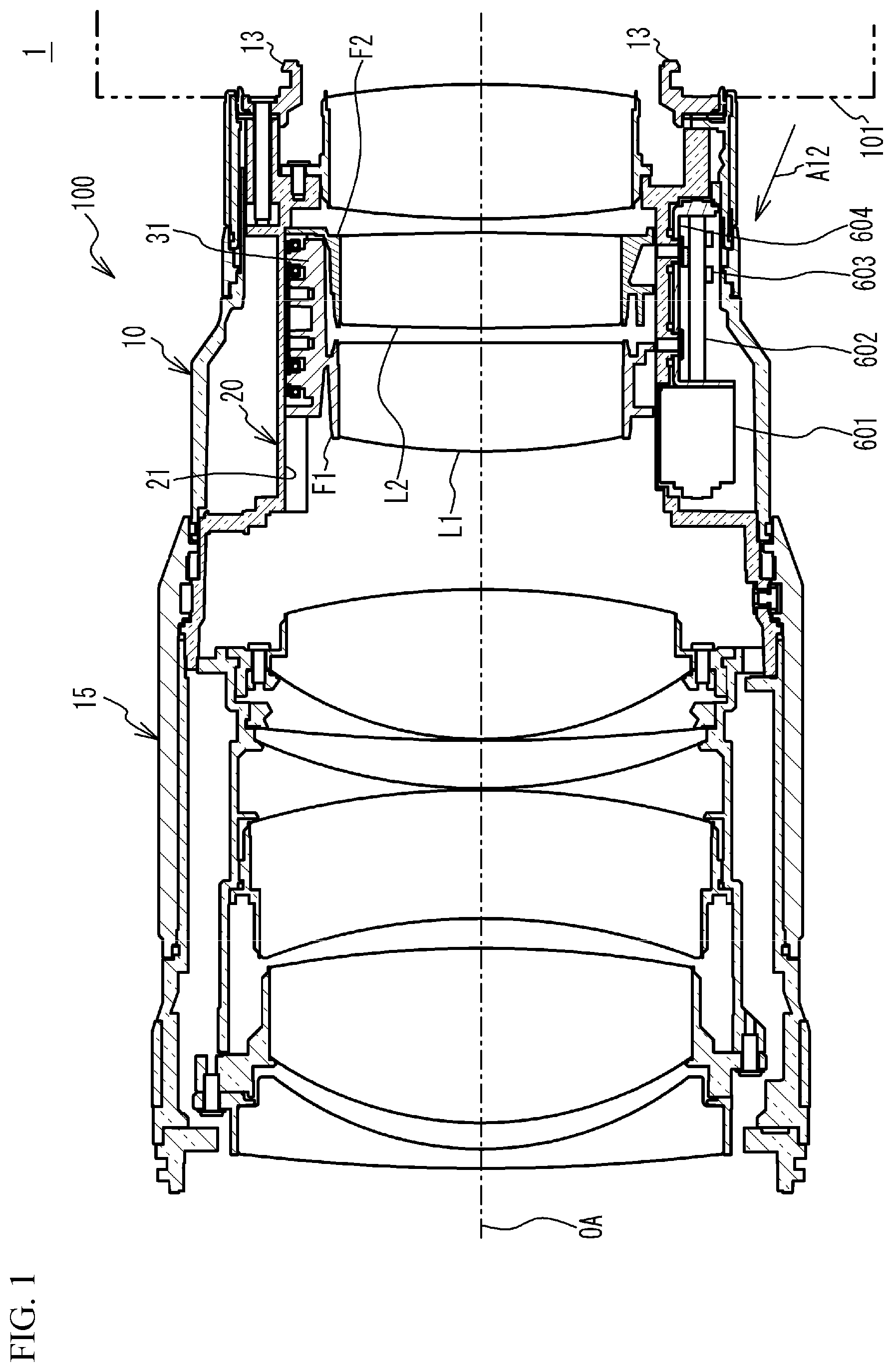
is a cross-sectional view of a lens barrel in accordance with an embodiment; A is a partial cross-sectional perspective view illustrating a relationship among a second fixed barrel, a first lens holding frame, and a second lens holding frame, and B is a partial cross-sectional view when the second fixed barrel is viewed from a direction indicated by an arrow A 10 in A ; is a cross-sectional view taken along line A-A in B ; A and B are cross-sectional views taken along line B-B in ; A is a schematic perspective view of the second fixed barrel viewed from a direction indicated by an arrow A 12 in , and B is an enlarged view of a first drive source unit; A is an enlarged view of a rack holding mechanism, and B illustrates the rack holding mechanism viewed from a direction indicated by an arrow A 1 in A ; A is a cross-sectional view taken along line A-A in B , B is a cross-sectional view taken along line B-B in B , and C is a cross-sectional view taken along line C-C in B ; A is an enlarged view of a rack-side surface of a shaft holding portion, and B is a side view of the rack; A and B illustrate an arrangement example of a first protruding portion and a second protruding portion in a straight groove in accordance with a first variation; illustrates an arrangement example of the first protruding portion and the second protruding portion in the straight groove in accordance with a second variation; A and B illustrate an arrangement example of the first protruding portion and the second protruding portion in the straight groove in accordance with a third variation; and A and B are views for describing a rack in accordance with a variation. MODES FOR CARRYING OUT THE INVENTION Hereinafter, embodiments will be described with reference to the drawings. is a diagram illustrating a camera 1 including a lens barrel 100 in accordance with the present embodiment and a camera body 101 . A is a partial cross-sectional perspective view illustrating a relationship among a second fixed barrel 20 , a first lens holding frame F 1 , and a second lens holding frame F 2 , which will be described later, and B is a partial cross-sectional view when the second fixed barrel 20 is viewed from a direction indicated by an arrow A 10 in A . is a cross-sectional view taken along line A-A in B . In the present embodiment, the lens barrel 100 is attachable to and detachable from the camera body 101 , but the present invention is not limited thereto, and the lens barrel 100 and the camera body 101 may be integrated. As illustrated in , the lens barrel 100 in accordance with the present embodiment includes a first fixed barrel 10 , the second fixed barrel 20 disposed further inward than the first fixed barrel 10 , and a focus ring 15 disposed further outward than the first fixed barrel 10 . In the present embodiment, the first fixed barrel 10 is composed of a plurality of components, but may be composed of one component. As illustrated in , a lens mount 13 that enables the lens barrel 100 to be attached to and detached from the camera body 101 is fixed to the first fixed barrel 10 . Further, the lens barrel 100 includes a plurality of lens groups that are sequentially arranged along a common optical axis OA and include a first lens group L 1 and a second lens group L 2 . Each of the first lens group L 1 and the second lens group L 2 is a focus lens group. The first lens group L 1 is held by a first lens holding frame F 1 , the second lens group L 2 is held by a second lens holding frame F 2 , and the other lens groups are held by the first fixed barrel 10 . Although the details will be described later, the first lens holding frame F 1 and the second lens holding frame F 2 are driven by a first drive source unit 60 and a second drive source unit 70 , respectively. As the first drive source unit 60 or the second drive source unit 70 , for example, a stepping motor, a voice coil motor, an ultrasonic motor, or the like can be used. As a result, for example, the first lens holding frame F 1 and the second lens holding frame F 2 move linearly in the optical axis OA direction individually or integrally in accordance with the operation of the focus ring 15 . As illustrated in A , the first lens holding frame F 1 and the second lens holding frame F 2 are disposed inside the second fixed barrel 20 . As illustrated in and A , the second fixed barrel 20 has a plurality of (three in the present embodiment) straight grooves 21 extending in the optical axis OA direction, and a hole 22 penetrating through the second fixed barrel 20 and extending in the optical axis OA direction. In the present embodiment, in a wall portion of a portion of the second fixed barrel 20 that accommodates the first lens holding frame F 1 and the second lens holding frame F 2 , an opening that penetrates through the wall portion (communicates the inside and the outside of the wall portion) is not formed other than the hole 22 . Therefore, it is possible to reduce light leakage from the outside to the inside of the second fixed barrel 20 , and it is also easy to take measures against light leakage. Further, the strength of the second fixed barrel 20 is also improved. As illustrated in , the first lens holding frame F 1 includes first protruding portions 31 that protrude in a direction intersecting the optical axis OA direction, and the second lens holding frame F 2 includes second protruding portions 41 that protrude in a direction intersecting the optical axis OA direction. The first protruding portions 31 and the second protruding portions 41 are engaged with the straight grooves 21 of the second fixed barrel 20 . More specifically, the first protruding portion 31 and the second protruding portion 41 are in contact with each other, and the first protruding portion 31 and the second protruding portion 41 are engaged with the straight groove 21 while being in contact with each other. A block 50 that is in contact with a wall 21 a is provided between the first protruding portion 31 and the wall 21 a of the straight groove 21 . The block 50 is assembled to the first lens holding frame F 1 so as to move integrally with the first lens holding frame F 1 (the first protruding portion 31 ) in the optical axis OA direction but be movable relative to the first protruding portion 31 in the circumferential direction around the optical axis OA. Since the first protruding portion 31 , the second protruding portion 41 , and the block 50 are engaged with the straight groove 21 , the rotation of the first lens holding frame F 1 and the second lens holding frame F 2 about the optical axis OA is restricted, and the first lens holding frame F 1 and the second lens holding frame F 2 are guided by the straight groove 21 and move linearly in the optical axis OA direction. Here, the relationship among the second fixed barrel 20 , the first protruding portion 31 of the first lens holding frame F 1 , the second protruding portion 41 of the second lens holding frame F 2 , and the block 50 will be described with reference to A and B . A and B are cross-sectional views taken along line B-B in , A illustrates a state in which the first lens group L 1 and the second lens group L 2 are most distant from each other in the optical axis OA direction, and B illustrates a state in which the first lens group L 1 and the second lens group L 2 are closest to each other in the optical axis OA direction. In A and B , the main body portion of the first lens holding frame F 1 and the main body portion of the second lens holding frame F 2 are not illustrated. As illustrated in A and B , compression springs 51 that bias the first protruding portion 31 and the block 50 in a direction in which the first protruding portion 31 and the block 50 move away from each other are provided between the first protruding portion 31 and the block 50 . The compression spring 51 may be another biasing member such as a leaf spring. The compression springs 51 press the block 50 against the wall 21 a of the straight groove 21 , and bias the first protruding portion 31 against the second protruding portion 41 . As a result, it is possible to reduce backlash when the first lens holding frame F 1 and the second lens holding frame F 2 move independently (it is possible to reduce backlash between the first lens holding frame F 1 and the second lens holding frame F 2 ), and it is possible to accurately move the first lens holding frame F 1 and the second lens holding frame F 2 in each of the straight grooves 21 . In addition, since the second protruding portion 41 is pressed against a wall 21 b of the straight groove 21 of the second fixed barrel 20 through the first protruding portion 31 by the compression springs 51 , backlash when the first lens holding frame F 1 and the second lens holding frame F 2 move is reduced, and the first lens holding frame F 1 and the second lens holding frame F 2 can be moved with high accuracy in the straight groove 21 . As illustrated in A and B , the first protruding portion 31 and the second protruding portion 41 at least partially overlap each other in the circumferential direction about the optical axis OA. More specifically, regardless of whether the first lens group L 1 and the second lens group L 2 are most distant from each other or closest to each other, the first protruding portion 31 and the second protruding portion 41 at least partially overlap each other in the circumferential direction about the optical axis OA. Thus, the first protruding portion 31 and the second protruding portion 41 can guide each other in the optical axis OA direction. The second protruding portion 41 of the second lens holding frame F 2 includes bearings 411 , and is in contact with one wall 21 b of the walls of the straight groove 21 in the circumferential direction. The first protruding portion 31 of the first lens holding frame F 1 has bearings 311 , and is in contact with the second protruding portion 41 . The block 50 includes bearings 501 and is in contact with the other wall 21 a of the walls of the straight groove 21 in the circumferential direction. As illustrated in A and B , plates 17 and 18 are attached to the first protruding portion 31 and the second protruding portion 41 , respectively, so that the bearings 311 , 411 , and 501 do not come off during assembly of the lens barrel 100 , but the plates 17 and 18 are not illustrated in and subsequent figures. The plates 17 and 18 may not be necessarily used. That is, the plates 17 and 18 may not be necessarily present between the bearings 311 , 411 , 501 and the straight groove 21 . When the first lens holding frame F 1 moves in the optical axis OA direction relative to the second lens holding frame F 2 and the second fixed barrel 20 , the sliding resistance between the first protruding portion 31 and the second protruding portion 41 and the sliding resistance between the block 50 and the wall 21 a can be reduced by the bearings 311 and the bearings 501 . Further, when the second lens holding frame F 2 moves in the optical axis OA direction relative to the first lens holding frame F 1 and the second fixed barrel 20 , the sliding resistance between the wall 21 b and the second protruding portion 41 and the sliding resistance between the first protruding portion 31 and the second protruding portion 41 can be reduced by the bearings 311 and the bearings 411 . Further, the sliding resistance when the first lens holding frame F 1 and the second lens holding frame F 2 move in the optical axis OA direction can be reduced by the bearings 411 and the bearings 501 . In the present embodiment, a case in which the first protruding portion 31 , the second protruding portion 41 , and the block 50 respectively include the bearings 311 , the bearings 411 , and the bearings 501 will be described. However, at least one of the first protruding portion 31 , the second protruding portion 41 , or the block 50 is only required to include a bearing. For example, a protrusion may be provided instead of the bearing. Next, drive mechanisms for driving the first lens holding frame F 1 and the second lens holding frame F 2 will be described. A is a schematic perspective view of the second fixed barrel 20 viewed from a direction indicated by an arrow A 12 in , and B is an enlarged view of the first drive source unit. In B , the second fixed barrel 20 is not illustrated. As illustrated in A , the first drive source unit 60 for moving the first lens holding frame F 1 in the optical axis OA direction and the second drive source unit 70 different from the first drive source unit 60 for moving the second lens holding frame F 2 in the optical axis OA direction are fixed to the outer peripheral portion of the second fixed barrel 20 . The first drive source unit 60 and the second drive source unit 70 are provided between two straight grooves 21 disposed side by side in the circumferential direction around the optical axis OA among the plurality of (for example, three) the straight grooves 21 included in the second fixed barrel 20 . Further, the first drive source unit 60 and the second drive source unit 70 are provided at positions facing each other with the hole 22 of the second fixed barrel 20 interposed therebetween. More specifically, the first drive source unit 60 and the second drive source unit 70 are disposed symmetrically with respect to the hole 22 in the circumferential direction around the optical axis OA. Next, the configurations of the first drive source unit 60 and the second drive source unit 70 will be described. As illustrated in B , the first drive source unit 60 includes a stepping motor 601 , a lead screw 602 , a rack 603 , and a mounting member 604 . The second drive source unit 70 includes a stepping motor 701 , a lead screw 702 , a rack 703 , and a mounting member 704 . Since the first drive source unit 60 and the second drive source unit 70 have the same configuration, the configuration of the first drive source unit 60 will be described below, and detailed description of the configuration of the second drive source unit 70 will be omitted. The mounting member 604 is a U-shaped member, and includes a first portion 604 a to which the stepping motor 601 is fixed, a second portion 604 b facing the first portion 604 a , and a third portion 604 c extending parallel to the lead screw 602 between the first portion 604 a and the second portion 604 b . A plurality of holes are formed in the third portion 604 c , and as illustrated in B , the first drive source unit 60 is fixed to the second fixed barrel 20 by screwing the mounting member 604 to the outer peripheral surface of the second fixed barrel 20 with screws or the like. Thus, the peripheral wall of the second fixed barrel 20 is present between the lead screw 602 and the first lens holding frame F 1 in the radial direction of the second fixed barrel 20 . Further, the lead screw 602 is disposed further outward than the third portion 604 c. The lead screw 602 is directly connected to the output shaft of the stepping motor 601 and extends in the optical axis OA direction. The tip of the lead screw 602 is rotatably supported by the second portion 604 b of the mounting member 604 . Since the tip of the lead screw 602 is rotatably supported by the second portion 604 b of the mounting member 604 , the deflection of the tip is suppressed. The rack 603 is engaged with the lead screw 602 . The rack 603 is held by a rack holding mechanism 33 provided in the first lens holding frame F 1 . The rack 703 of the second drive source unit 70 is held by a rack holding mechanism 43 provided in the second lens holding frame F 2 (see A ). Here, the rack 603 and the rack holding mechanism 33 will be described. The rack 703 and the rack holding mechanism 43 have configurations similar to those of the rack 603 and the rack holding mechanism 33 , respectively. A is an enlarged view of the rack 603 and the rack holding mechanism 33 , and B illustrates the rack 603 and the rack holding mechanism 33 when viewed from a direction indicated by an arrow A 1 in A . A is a cross-sectional view taken along line A-A in B , B is a cross-sectional view taken along line B-B in B , and C is a cross-sectional view taken along line C-C in B . A is an enlarged view of a rack-side surface of a shaft holding portion, and B is a side view of the rack. As illustrated in A and the like, the rack 603 includes a rack body 611 and a biasing member 612 . As illustrated in B , the rack body 611 includes a first sidewall portion 611 a , a second sidewall portion 611 b opposed to the first sidewall portion 611 a , and a connecting portion 611 c connecting the first sidewall portion 611 a and the second sidewall portion 611 b . A through-hole 611 d into which a first member 331 a of the rack holding shaft 331 is inserted is formed in the connecting portion 611 c. The first sidewall portion 611 a , the second sidewall portion 611 b , and the connecting portion 611 c are formed of one member. The rack body 611 is made of a flexible resin such as polyacetal. The first sidewall portion 611 a has two first contact portions 613 a in contact with the lead screw 602 , and the second sidewall portion 611 b has one second contact portion 613 b in contact with the lead screw 602 . The first contact portions 613 a and the second contact portion 613 b are configured to sandwich the lead screw 602 . Further, the first contact portions 613 a and the second contact portion 613 b are alternately arranged. Screw threads having a shape complementary to the screw threads of the lead screw 602 are formed on the inner surfaces of the first contact portions 613 a and the second contact portion 613 b. The biasing member 612 is, for example, a leaf spring, one end of which is engaged with the first sidewall portion 611 a and the other end of which is engaged with the second sidewall portion 611 b , and biases the first sidewall portion 611 a and the second sidewall portion 611 b inward with substantially the same force as indicated by arrows in B . Accordingly, since the first contact portions 613 a and the second contact portion 613 b are biased to approach each other, the screw threads formed on the inner surfaces of the first contact portions 613 a and the second contact portion 613 b are in close contact with the screw threads formed on the lead screw 602 . As a result, backlash between the lead screw 602 and the rack 603 is reduced. As long as the first sidewall portion 611 a and the second sidewall portion 611 b can be biased inward with substantially the same force, a biasing member such as a torsion coil spring may be used as the biasing member 612 . Next, the rack holding mechanism 33 will be described in detail. As illustrated in A to A , the rack holding mechanism 33 includes a rack holding shaft 331 , a shaft holding portion 332 , and a compression spring 333 . As illustrated in , the shaft holding portion 332 protrudes from the outer periphery of the first lens holding frame F 1 in a direction intersecting the optical axis OA direction, and passes through the hole 22 of the second fixed barrel 20 . As illustrated in A , the shaft holding portion 332 has a through-hole 332 a through which the rack holding shaft 331 is inserted. The through-hole 332 a is a stepped through-hole. The through-hole 332 a is located further outward than the outer peripheral surface of the second fixed barrel 20 . Further, the shaft holding portion 332 is provided with a light shielding portion 334 that passes between the detection portions of a photointerrupter (not illustrated). Thus, the position of the first lens holding frame F 1 can be detected. The light shielding portion 334 is disposed further outward than the second fixed barrel 20 . The rack holding shaft 331 has the first member 331 a and a second member 331 b . The first member 331 a has a flange portion 331 a 1 , is inserted into the through-hole 611 d of the rack body 611 , and has one end inserted into the through-hole 332 a of the shaft holding portion 332 , thereby holding the rack 603 between the flange portion 331 a 1 and the shaft holding portion 332 . The second member 331 b is inserted into the shaft holding portion 332 from the side opposite to the first member 331 a and is coupled to the first member 331 a . Since the through-hole 332 a of the shaft holding portion 332 is positioned further outward than the outer peripheral surface of the second fixed barrel 20 , the rack 603 held by the rack holding shaft 331 inserted into the through-hole 332 a is disposed further outward than the second fixed barrel 20 . The first member 331 a is biased in a direction indicated by an arrow A 3 in A by the compression spring 333 disposed in the through-hole 332 a of the shaft holding portion 332 . Accordingly, the rack 603 is also biased in the direction indicated by the arrow A 3 and is pressed against the shaft holding portion 332 . Since the rack 603 is not completely fixed to the shaft holding portion 332 , the rack 603 can swing (rotate) around the axis of the rack holding shaft 331 . Therefore, as compared with a case in which the rack 603 is directly screwed to the shaft holding portion 332 , it is possible to inhibit an unnecessary force from being applied to the first lens holding frame F 1 . Thus, the load applied to the stepping motor 601 can be reduced. As illustrated in A , spherical protruding portions 332 d are formed on a surface 332 c of the shaft holding portion 332 that is in contact with the rack 603 , and the protruding portions 332 d are in contact with the rack 603 . As illustrated in B and C , the through-hole 332 a of the shaft holding portion 332 is formed such that the first member 331 a and the second member 331 b are movable in the radial direction of the first lens holding frame F 1 indicated by arrows A 5 and A 7 but are not movable in the circumferential direction around the optical axis OA indicated by arrows A 6 and A 8 . That is, the through-hole 332 a is formed such that gaps are present between the side surface of the through-hole 332 a and the first member 331 a and between the side surface of the through-hole 332 a and the second member 331 b in the radial direction indicated by the arrows A 5 and A 7 , but the side surface of the through-hole 332 a is in contact with the first member 331 a and the second member 331 b (there is no gap between the through-hole 332 a and the first member 331 a and between the through-hole 332 a and the second member 331 b ) in the circumferential direction indicated by the arrows A 6 and A 8 . Accordingly, backlash in the circumferential direction is eliminated, and the followability of the rack 603 with respect to the lead screw 602 in the circumferential direction is improved. The rack 603 is biased in the direction indicated by the arrow A 3 , and the side surface of the rack 603 is in contact with the spherical protrusion portions 332 d . Further, the rack holding shaft 331 is held by the shaft holding portion 332 so as to be movable in the radial direction of the first lens holding frame F 1 about the optical axis OA. This allows the rack 603 to swing as indicated by an arrow A 4 in A . Further, as described above, the rack 603 is rotatable about the axis of the rack holding shaft 331 . Although it is difficult to make the axial direction of the lead screw 602 completely parallel to the optical axis OA direction, according to the present embodiment, the above-described configuration allows the rack 603 to follow the lead screw 602 , and the movement accuracy of the first lens holding frame F 1 in the optical axis OA direction can be improved. Since the rack holding mechanisms 33 and 43 have substantially the same configuration, detailed description of the rack holding mechanism 43 will be omitted. More specifically, as illustrated in , the rack holding mechanism 43 includes a shaft holding portion 432 similar to the shaft holding portion 332 , a light shielding portion 434 similar to the light shielding portion 334 , a through-hole 432 a similar to the through-hole 332 a , and the like. As described above in detail, the lens barrel 100 in accordance with the present embodiment includes the first lens holding frame F 1 that holds the first lens group L 1 and has the first protruding portion 31 , the stepping motor 601 that moves the first lens holding frame F 1 in the optical axis OA direction, the second lens holding frame F 2 that holds the second lens group L 2 and has the second protruding portion 41 , the stepping motor 701 that moves the second lens holding frame F 2 in the optical axis OA direction, and the second fixed barrel 20 that has the straight groove 21 engaging with the first protruding portion 31 and the second protruding portion 41 and extending in the optical axis OA direction, and is disposed further outward than the first lens holding frame F 1 and the second lens holding frame F 2 . Accordingly, it is possible to restrict the rotation of the first lens holding frame F 1 and the second lens holding frame F 2 around the optical axis OA and to linearly move the first lens holding frame F 1 and the second lens holding frame F 2 in the optical axis OA direction. In addition, since the first protruding portion 31 of the first lens holding frame F 1 and the second protruding portion 41 of the second lens holding frame F 2 share one straight groove 21 , the second fixed barrel 20 can have a simple structure, and the first lens holding frame F 1 and the second lens holding frame F 2 can be moved in the optical axis direction with high accuracy. In the present embodiment, the first protruding portion 31 and the second protruding portion 41 at least partially overlap each other in the circumferential direction about the optical axis OA. Thus, the first protruding portion 31 and the second protruding portion 41 can guide each other in the optical axis OA direction in the straight groove 21 . Further, the length of the straight groove 21 in the optical axis OA direction can be shortened. Further, in the present embodiment, in the circumferential direction around the optical axis OA, the first protruding portion 31 and the second protruding portion 41 are in contact with each other, and the second protruding portion 41 is in contact with one wall 21 b of the straight groove 21 . Further, the lens barrel 100 includes the block 50 movable relative to the first protruding portion 31 in the circumferential direction around the optical axis OA, and the compression springs 51 disposed between the first protruding portion 31 and the block 50 . The block 50 is in contact with the other wall 21 a of the straight groove 21 . This configuration reduces backlash when the first lens holding frame F 1 and the second lens holding frame F 2 move independently. Further, it is possible to reduce backlash between the first lens holding frame F 1 and the second lens holding frame F 2 . In a guide bar type lens barrel in which a lens holding frame is linearly guided along a guide bar in the optical axis OA direction, the lens holding frame is often biased against the guide bar by a biasing member such as a spring so that backlash does not occur between the lens holding frame and the guide bar when a camera is inclined. In this case, since a sliding resistance between the lens holding frame and the guide bar increases and a force by the biasing member is applied to the lens holding frame, a relatively large torque is required for moving the lens holding frame, and it may be difficult to drive the lens holding frame with a small stepping motor. In contrast, in the lens barrel 100 in accordance with the present embodiment, since the first lens holding frame F 1 and the second lens holding frame F 2 are biased by the block 50 and the compression spring 51 in the directions in which the first lens holding frame F 1 and the second lens holding frame F 2 come into contact with the walls 21 a and 21 b , respectively, in each of the three straight grooves 21 , an excessive force is not applied to the first lens holding frame F 1 or the second lens holding frame F 2 . Therefore, it is possible to drive the first lens holding frame F 1 and the second lens holding frame F 2 even by using a small stepping motor having a relatively small torque. Therefore, it is possible to accurately move the first lens holding frame F 1 and the second lens holding frame F 2 in the optical axis OA direction. Further, in the present embodiment, each of the first protruding portion 31 , the second protruding portion 41 , and the block 50 has a bearing. Therefore, it is possible to reduce sliding resistance when the first lens holding frame F 1 and the second lens holding frame F 2 move. Further, in the present embodiment, the second fixed barrel 20 has a plurality of the straight grooves 21 , and the stepping motor 601 and the stepping motor 701 are disposed between two straight grooves 21 disposed side by side in the circumferential direction about the optical axis OA among the plurality of the straight grooves 21 . Therefore, the stepping motor 601 and the stepping motor 701 can be arranged in a well-balanced manner. Further, since the stepping motors 601 and 701 can be arranged in an empty space between the first fixed barrel 10 and the second fixed barrel 20 , the lens barrel 100 can be miniaturized. In the present embodiment, the lens barrel 100 includes the lead screw 602 rotated by the stepping motor 601 and the rack body 611 held by the first lens holding frame F 1 and engaged with the lead screw 602 , the rack body 611 includes the first sidewall portion 611 a , the second sidewall portion 611 b , and the connecting portion 611 c connecting the first sidewall portion 611 a and the second sidewall portion 611 b , and the first sidewall portion 611 a , the second sidewall portion 611 b , and the connecting portion 611 c are composed of one member. Since the number of components is reduced, it is possible to reduce failures compared to a case in which the rack body 611 is composed of a plurality of members. Further, the first sidewall portion 611 a has the first contact portion 613 a that is in contact with the lead screw 602 , the second sidewall portion 611 b has the second contact portion 613 b in contact with the lead screw 602 , and the lens barrel 100 includes the biasing member 612 that biases the rack body 611 so that the first contact portion 613 a and the second contact portion 613 b approach each other. This configuration brings the screw threads formed on the inner surfaces of the first contact portion 613 a and the second contact portion 613 b into close contact with the screw threads formed on the lead screw 602 , thereby reducing backlash. In addition, for example, when one of the first sidewall portion 611 a and the second sidewall portion 611 b is biased using a torsion spring or the like to bring the screw threads formed on the inner surface of the first contact portion 613 a or the second contact portion 613 b into close contact with the screw threads formed on the lead screw 602 , a reaction force of the force against the first sidewall portion 611 a or the second sidewall portion 611 b is applied to the first lens holding frame F 1 through the rack body 611 and the rack holding shaft 331 , and affects the first lens holding frame F 1 supported in a well-balanced manner by the three straight grooves 21 . In the present embodiment, since the first contact portion 613 a and the second contact portion 613 b are biased toward the lead screw 602 with substantially the same force, no reaction force is generated in the rack body 611 . Therefore, it is possible to inhibit an unnecessary force from being applied to the first lens holding frame F 1 . Therefore, the first lens holding frame F 1 can be held in the second fixed barrel 20 in a well-balanced manner. The same applies to the second lens holding frame F 2 . As described in detail above, the lens barrel 100 in accordance with the present embodiment includes the stepping motor 601 , the lead screw 602 rotated by the stepping motor 601 , the rack 603 engaged with the lead screw 602 , the first lens holding frame F 1 holding the first lens group L 1 , and the second fixed barrel 20 disposed further outward than the first lens holding frame F 1 , and the peripheral wall of the second fixed barrel 20 exists between the lead screw 602 and the first lens holding frame F 1 . Since the peripheral wall of the second fixed barrel 20 is interposed between the first lens holding frame F 1 and the lead screw 602 , lubricant applied to the lead screw 602 and dust generated by sliding between the lead screw 602 and the rack 603 can be inhibited from adhering to the first lens group L 1 and the second lens group L 2 as compared with a case in which the lead screw 602 is disposed between the second fixed barrel 20 and the first lens holding frame F 1 (a case in which the lead screw 602 is disposed further inward than the second fixed barrel 20 ). Further, in the present embodiment, the lens barrel 100 includes the mounting member 604 that fixes the stepping motor 601 to the second fixed barrel 20 , and the lead screw 602 is disposed further outward than the third portion 604 c of the mounting member 604 . In addition, in the present embodiment, the rack 603 is disposed further outward than the third portion 604 c of the mounting member 604 . Further, the rack 603 is disposed further outward than the second fixed barrel 20 . As a result, the components of the first drive source unit 60 that drives the first lens holding frame F 1 can be disposed further outward than the second fixed barrel 20 , that is, the second fixed barrel 20 can be interposed between the first drive source unit 60 and the first lens holding frame F 1 , so that the second fixed barrel 20 can inhibit dust from adhering to the first lens group L 1 and the second lens group L 2 . The same applies to the second drive source unit 70 . Further, in the present embodiment, the second fixed barrel 20 has the hole 22 for arranging the rack 603 further outward than the second fixed barrel 20 . Since there is no need to form a hole other than the hole 22 in the wall surface of the portion of the second fixed barrel 20 that accommodates the first lens holding frame F 1 and the second lens holding frame F 2 , it is possible to reduce light leakage. Further, in the present embodiment, the first lens holding frame F 1 has the light shielding portion 334 that is detected by the photointerrupter (not illustrated) that detects the position of the first lens holding frame F 1 , and the light shielding portion 334 is disposed further outward than the second fixed barrel 20 . Thus, since the light from the light emitting part of the photointerrupter can be blocked by the second fixed barrel 20 , the influence of the light of the photointerrupter on imaging can be reduced. In the above embodiment, at least a part of the stepping motor 601 is only required to be disposed further outward than the second fixed barrel 20 . That is, a part of the stepping motor 601 may be disposed further inward than the second fixed barrel 20 . In addition, in the above embodiment, the second fixed barrel 20 that houses the first lens holding frame F 1 and the second lens holding frame F 2 may be a movable barrel that can linearly move in the optical axis OA direction. In the above embodiment, the lens barrel 100 may be a single focus lens or a zoom lens. Further, the first drive source unit 60 and the second drive source unit 70 in accordance with the above embodiment may be applied to a guide bar type lens barrel in which the first lens holding frame F 1 and the second lens holding frame F 2 are linearly moved in the optical axis OA direction along a guide bar. Further, the lens barrel 100 may include only one of the first lens holding frame F 1 and the second lens holding frame F 2 . That is, to inhibit the intrusion of dust or the like, the configuration in which the peripheral wall of the second fixed barrel 20 is present between the lens holding frame and the lead screw can be applied to both a case in which there are a plurality of lens groups and a case in which there is only one lens group. In the above embodiment, at least one of the bearings 311 included in the first protruding portion 31 and the bearings 411 included in the second protruding portion 41 may have a diameter different from those of the other bearings 311 and 411 . For example, one of the two bearings 311 may have a different diameter than the other bearing 311 . Also, one of the two bearings 411 may have a different diameter than the other bearing 411 . Also, one of the two bearings 311 may have a different diameter than one or both of the two bearings 411 . In addition, all of the two bearings 311 and the two bearings 411 may have different diameters. As described above, by changing the diameters of the bearings 311 and 411 , it is possible to perform tilt adjustment and alignment of the first lens holding frame F 1 and the second lens holding frame F 2 . In the above embodiment, the compression springs 51 are provided between the first protruding portion 31 and the block 50 , but this does not intend to suggest any limitation. Here, an arrangement example of the first protruding portion 31 and the second protruding portion 41 in accordance with variations will be described with reference to A to B . (First Variation) A is a diagram illustrating an arrangement example of a first protruding portion 31 A and a second protruding portion 41 A in accordance with a first variation. B illustrates a state in which the bearings 311 and 411 are removed in A . As illustrated in A , in the first variation, the first protruding portion 31 A has the bearings 311 , and the bearings 311 are in contact with one wall 21 a of the straight groove 21 . The second protruding portion 41 A has the bearings 411 , and the bearings 411 are in contact with the other wall 21 b of the straight groove 21 . Two pressing members 81 are provided between the first protruding portion 31 A and the second protruding portion 41 A. As illustrated in B , one end of the pressing member 81 is engaged with a protrusion 412 of the second protruding portion 41 A, and the other end of the pressing member 81 is partially in contact with a protrusion 312 of the first protruding portion 31 A. The two pressing members 81 are connected by a tension spring 82 . When the pressing members 81 are pulled by the tension spring 82 , the protrusion 312 and the protrusion 412 are pushed along an inclined surface 81 a formed at the other end of the pressing member 81 in a direction in which the first protruding portion 31 A and the second protruding portion 41 A move away from each other. Accordingly, since the first protruding portion 31 A and the second protruding portion 41 A are respectively pressed against the wall 21 b and the wall 21 a , backlash when the first lens holding frame F 1 and the second lens holding frame F 2 linearly move in the optical axis OA direction along the straight groove 21 is reduced. (Second Variation) is a diagram illustrating an arrangement example of a first protruding portion 31 B and a second protruding portion 41 B in accordance with a second variation. In the second variation, a first block 85 having a bearing 851 and a second block 86 having a bearing 861 are provided between the first protruding portion 31 B and the second protruding portion 41 B. A compression spring 87 is provided between the first block 85 and the second block 86 . The compression spring 87 biases the first block 85 and the second block 86 in a direction in which the first block 85 and the second block 86 move away from each other, as indicated by arrows A 21 . As a result, the first block 85 and the second block 86 push up inclined faces 313 a and 313 b formed on the first protruding portion 31 B, respectively, and push up inclined faces 413 a and 413 b formed on the second protruding portion 41 B, respectively. As a result, the first protruding portion 31 B and the second protruding portion 41 B are biased in a direction in which the first protruding portion 31 B and the second protruding portion 41 B move away from each other and are pressed against the wall 21 a and the wall 21 b , respectively. Therefore, backlash when the first lens holding frame F 1 and the second lens holding frame F 2 linearly move in the optical axis OA direction along the straight groove 21 is reduced. (Third Variation) A is a diagram illustrating an arrangement example of a first protruding portion 31 C and a second protruding portion 41 C in accordance with a third variation, and B is a cross-sectional view taken along line D-D of A . As illustrated in A , in the third variation, the straight groove 21 included in the second fixed barrel 20 includes a protruding portion 211 , and the first protruding portion 31 C and the second protruding portion 41 C are connected by a tension spring 88 . The first protruding portion 31 C has the bearings 311 and is in contact with one sidewall portion 211 a of the protruding portion 211 . The second protruding portion 41 C has the bearings 411 , and is in contact with another sidewall portion 211 b of the protruding portion 211 . The tension spring 88 biases the first protruding portion 31 C and the second protruding portion 41 C in a direction in which the first protruding portion 31 and the second protruding portion 41 approach each other. As a result, the first protruding portion 31 C is pressed against the sidewall portion 211 a , and the second protruding portion 41 C is pressed against the sidewall portion 211 b . Therefore, backlash when the first lens holding frame F 1 and the second lens holding frame F 2 linearly move in the optical axis OA direction along the straight groove 21 is reduced. Further, the configuration of the rack 603 is not limited to the above embodiment. A and B illustrate a rack 603 A in accordance with a variation. As illustrated in A , a rack body 611 A of the rack 603 A includes the first sidewall portion 611 a , the second sidewall portion 611 b , and the connecting portion 611 c connecting the first sidewall portion 611 a and the second sidewall portion 611 b , and the first sidewall portion 611 a , the second sidewall portion 611 b , and the connecting portion 611 c are formed of one member. In the variation, the end of the first contact portion 613 a of the first sidewall portion 611 a and the end of the second contact portion 613 b of the second sidewall portion 611 b are connected by a tension spring 612 A. As a result, the first contact portion 613 a and the second contact portion 613 b are biased obliquely toward each other as indicated by arrows A 22 in B . Thus, since the screw threads formed on the inner side of the first contact portion 613 a and the screw threads formed on the inner side of the second contact portion 613 b are in close contact with the screw threads of the lead screw 602 , it is possible to reduce backlash. In addition, since the first contact portion 613 a and the second contact portion 613 b are biased toward the lead screw 602 with substantially the same force, no reaction force is generated in the rack body 611 A. Therefore, it is possible to inhibit an unnecessary force from being applied to the first lens holding frame F 1 . Thus, the first lens holding frame F 1 can be held in the second fixed barrel 20 in a well-balanced manner. The above-described embodiments are examples of preferred implementations. However, the present invention is not limited to this, and various modifications can be made without departing from the scope of the invention, and arbitrary constituent elements may be combined. The disclosures of the publications cited in the above description are incorporated herein by reference. DESCRIPTION OF REFERENCE NUMERALS 1 camera 10 first fixed barrel 20 second fixing barrel 21 straight groove 21 a , 21 b wall 22 hole 31 first protruding portion 41 second protruding portion 50 block 51 compression spring 60 first drive source unit 70 second drive source unit 100 lens barrel 311 , 411 , 501 bearing 601 , 701 stepping motor 602 , 702 lead screw 603 , 703 rack 611 rack body 611 a first sidewall portion 611 b second sidewall portion 611 c connecting portion 612 biasing member 612 A tension spring 613 a first contact portion 613 b second contact portion F 1 first lens holding frame F 2 second lens holding frame L 1 first lens group L 2 second lens group
Figures (12)
Citations
This patent cites (12)
- US2006/0176586
- US2011/0181967
- US2014/0169781
- US2018/0017758
- US2019/0064475
- US2020/0225441
- US102099739
- US107111099
- US111133354
- US2010-020067
- US2019-032565
- US6819433