Dust Extractor Having an Electric Outlet Connectable to a Power Tool
Abstract
A dust extractor having an autostart functionality that includes: a motor and a fan to generate an air flow; an electric outlet connectable to a power tool; a control system; a user interface; and a current measuring unit to measure electric current of the outlet, wherein the control system is arranged to: measure a first representative current value of the electric outlet, associate the first representative current value with a first state of the power tool based on a first user input received via the user interface, determine a first threshold value from the first representative current value associated with the first state of the power tool, measure the electric current of the outlet, compare the measured electric current with the threshold value, and control the suction air flow of the dust extractor based on a result of the comparison.
Claims (13)
1 . A dust extractor, comprising: a motor and a fan to generate an air flow, a dust separator to separate dust particles from the air flow, an electric outlet connectable to a power tool, a control system, a user interface, and a current measuring unit to measure electric current of the outlet, wherein the control system is arranged to: measure a first representative current value of the electric outlet by using the current measuring unit, associate the first representative current value with a first state of the power tool when a user confirms by providing a first user input via the user interface that the power tool is operating in the first state, determine a first threshold value from the first representative current value associated with the first state of the power tool, measure the electric current of the outlet, compare the measured electric current with the first threshold value, and control an air flow of the dust extractor based on a result of said comparison, wherein the control system is arranged to provide a first prompt to the user via the user interface so as to indicate that the control system is ready to receive the first user input.
8 . A method for operating a dust extractor, the dust extractor comprising: a motor and a fan to generate an air flow, a dust separator to separate dust particles from the air flow, an electric outlet connected to a power tool, and a current measuring unit to measure electric current of the outlet, the method comprising: measuring a first representative current value of the electric outlet by using the current measuring unit when the power tool is in a first state, associating the first representative current value with the first state of the power tool when a user confirms by providing a first user input via a user interface that the power tool is operating in the first state, determining a first threshold value from the first representative current value, measuring the electric current of the outlet, comparing the measured electric current with the first threshold value, and controlling an air flow of the dust extractor based on a result of said comparison, wherein the method further comprises providing a first prompt to the user via the user interface so as to indicate that a control system is ready to receive the first user input.
Show 11 dependent claims
2 . The dust extractor of claim 1 , wherein the control system is arranged to: determine a first measurement time based on the first user input received via the user interface, and measure the first representative current value at the first measurement time.
3 . The dust extractor according to claim 1 , wherein the control system is arranged to: measure a second representative current value of the electric outlet, associate the second representative current value with a second state of the power tool based on a second user input received via the user interface, determine said first threshold value from the first representative current value and from the second representative current value.
4 . The dust extractor according to claim 3 , wherein the control system is arranged to: determine a second measurement time based on the second user input received via the user interface, and measure the second representative current value at the second measurement time.
5 . The dust extractor of claim 4 , wherein the control system is arranged to provide a second prompt via the user interface so as to indicate that the control system is ready to receive the second user input.
6 . The dust extractor according to claim 1 , wherein the control system is arranged to: start the air flow of the dust extractor when the measured electric current of the electric outlet increases to or exceeds the first threshold value, and/or stop the air flow when the electric current falls to or below a second threshold value.
7 . The dust extractor of claim 1 , wherein the first state of the power tool is an operating state where the motor of the power tool is running without a load during an idling time period.
9 . The method of claim 8 , comprising: determining a first measurement time based on the first user input received via the user interface, and measuring the first representative current value at the first measurement time.
10 . The method according to claim 8 , comprising: measuring a second representative current value of the electric outlet when the power tool is in a second state, associating the second representative current value with the second state based on a second user input received via the user interface, determining said first threshold value from the first representative current value and from the second representative current value.
11 . The method of claim 10 , comprising: determining a second measurement time based on the second user input received via the user interface, and measuring the second representative current value at the second measurement time.
12 . The method of claim 11 , comprising providing a second prompt via the user interface so as to indicate that a control system is ready to receive the second user input.
13 . The method according to claim 8 , comprising: starting the air flow of the dust extractor when the measured electric current of the electric outlet increases to or exceeds the first threshold value, and/or stopping the air flow when the electric current falls to or below a second threshold value.
Full Description
Show full text →
CROSS-REFERENCE TO RELATED APPLICATIONS
This application is a National Phase of PCT/FI2023/050095, filed on Feb. 16, 2023, which claims priority to Finnish Patent Application No. 20225174, filed on Feb. 25, 2022, the disclosures of each of which are hereby incorporated by reference in their entireties. FIELD Some embodiments relate to a dust extractor.
BACKGROUND
A power tool may generate dust particles during operation. The generated dust particles may be removed via a hose by using a dust extractor. The air flow of the dust extractor may be manually started before the power tool starts to generate dust particles, and the air flow of the dust extractor may be manually stopped after the power tool has stopped to generate dust particles. It is known that the dust extractor may comprise an electric socket for providing electric power to the power tool. The dust extractor may measure the electric current drawn via the electric socket. The dust extractor may start the air flow when the measured electric current exceeds a predetermined threshold value, which has been previously set at a factory.
SUMMARY
An object of the invention is to provide a dust extractor device. An object of the invention is to provide an apparatus, which comprises a dust extractor device. An object of the invention is to provide a method for extracting dust. An object of the invention is to provide a method for processing a surface. According to an aspect, there is provided a dust extractor ( 500 ), comprising: a motor (MOTOR 1 ) and a fan (FAN 1 ) to generate an air flow (AIR 1 ), a dust separator (FIL 1 ) to separate dust particles (DUST 1 ) from the air flow (AIR 1 ), an electric outlet (SOC 1 ) connectable to a power tool (TOOL 1 ), a control system (SYS 1 ), a user interface (UIF 1 ), and a current measuring unit (AM 1 ) to measure electric current (IAM 1 ) of the outlet (SOC 1 ), wherein the control system (SYS 1 ) is arranged to: measure a first representative current value (IR 1 ) of the electric outlet (SOC 1 ), associate the first representative current value (IR 1 ) with a first state (STATE 1 ) of the power tool (TOOL 1 ) based on a first user input (INPUT 1 ) received via the user interface (UIF 1 ), determine a first threshold value (LIM 1 ) from the first representative current value (IR 1 ) associated with the first state (STATE 1 ) of the power tool (TOOL 1 ), measure the electric current (IAM 1 ) of the outlet (SOC 1 ), compare the measured the electric current (IAM 1 ) with the threshold value (LIM 1 ), and control an air flow (AIR 1 ) of the dust extractor ( 500 ) based on a result of said comparison. The scope of protection sought for various embodiments of the invention is set out by the independent claims. The embodiments, if any, described in this specification that do not fall under the scope of the independent claims are to be interpreted as examples useful for understanding various embodiments of the invention. A power tool may be connected to an electric outlet of the dust extractor. The operation of the dust extractor may be controlled based on the electric current drawn from the electric outlet of the dust extractor. The suction air flow of the dust extractor may be started when the motor of the power tool starts to draw a significant current from the electric outlet. The suction air flow of the dust extractor may be stopped when the motor of the power tool is not running. The dust extractor has an autostart functionality, which means that the air flow may be started when the measured electric current of the outlet increases to or exceeds a threshold value, and the air flow may be stopped when the electric current falls to or below a threshold value. Controlling the suction air flow based on the measured outlet current may e.g. reduce energy consumption of the dust extractor, may increase operating lifetime of the dust extractor and/or may reduce average level of acoustic noise generated by the air flow. The same dust extractor may be used with several different power tools, which may have different operating currents. A first power tool may draw a higher operating current from the electric outlet of the dust extractor, and a second power tool may draw a lower operating current from the outlet. An optimum threshold value for using the dust extractor with the first power tool may be quite high e.g. to minimize the risk of unintentional start of the air flow. However, the high threshold value determined for the first power tool may be too high for the second power tool, which draws the lower operating current. Using the high threshold value with the second power tool may cause unreliable operation. For example, the threshold value may be so high that the electric current of the second power tool is not sufficient to start the air flow when needed. The present method may comprise determining an optimum threshold value for each different power tool, which is connected to the outlet of the dust extractor. The present method may ensure reliable auto start functionality with each different power tool. The present method may comprise a learning stage and a usage stage. One or more tool-specific threshold values may be determined from measured outlet currents in the learning stage. The air flow of the dust extractor may be controlled based on the measured outlet current in the usage stage. The power tool may have a first state where the motor of the power tool is rotating. The power tool may have a second state where the motor of the power tool is not rotating. The second state also be called e.g. as a standby state or as a power off state. By way of example, the method may comprise: starting a learning stage e.g. by pressing a button of the interface of the dust extractor, or by connecting a power tool to the electric outlet of the dust extractor, displaying a prompt to press a button when the power tool is in a first state, setting the power tool to the first state, measuring a first representative current value associated with the first state by pressing the button when the power tool is in the first state, displaying a prompt to press a button when the power tool is in a second state, setting the power tool to the second state, measuring a second representative current value associated with the second state by pressing the button when the power tool is in the second state, determining one or more threshold values from the representative current values, starting a usage stage when the one or more threshold values have been determined, continuously or intermittently measuring electric current of the electric outlet, comparing the measured electric current with the one or more threshold values, and controlling the suction air flow of the dust extractor based on a result of the comparison. The control system of the dust extractor may be configured to calculate the threshold values, so as to accommodate the dust extractor's electric outlet to the connected power tool. The dust extractor may give the user a possibility to set the autostart ON/OFF levels based on the actual measured electric currents. Determining the threshold levels based on the measured currents may ensure proper operation of the auto start when using different power tools with the same dust extractor. Determining the threshold levels based on the measured currents may ensure proper operation of the auto start e.g. when using a first power tool, which draws a high current from the outlet, and also when using second different power tool, which draws a low current from the outlet.
BRIEF DESCRIPTION OF THE DRAWINGS
In the following examples, several variations will be described in more detail with reference to the appended drawings, in which a shows, by way of example, temporal evolution of electric current of a first power tool, b shows, by way of example, temporal evolution of electric current of a second power tool, a shows, by way of example, temporal evolution of electric current of the second power tool, b shows, by way of example, temporal evolution of electric current of the first power tool, a shows, by way of example, method steps for determining a threshold value for controlling operation of the dust extractor, and method steps for controlling operation of the dust extractor, b shows, by way of example, method steps for determining a threshold value for controlling operation of the dust extractor, and method steps for controlling operation of the dust extractor, a shows, by way of example, a surface processing apparatus, b shows, by way of example, a power tool, c shows, by way of example, the dust extractor, and shows, by way of example, a control system of the dust extractor.
DETAILED DESCRIPTION
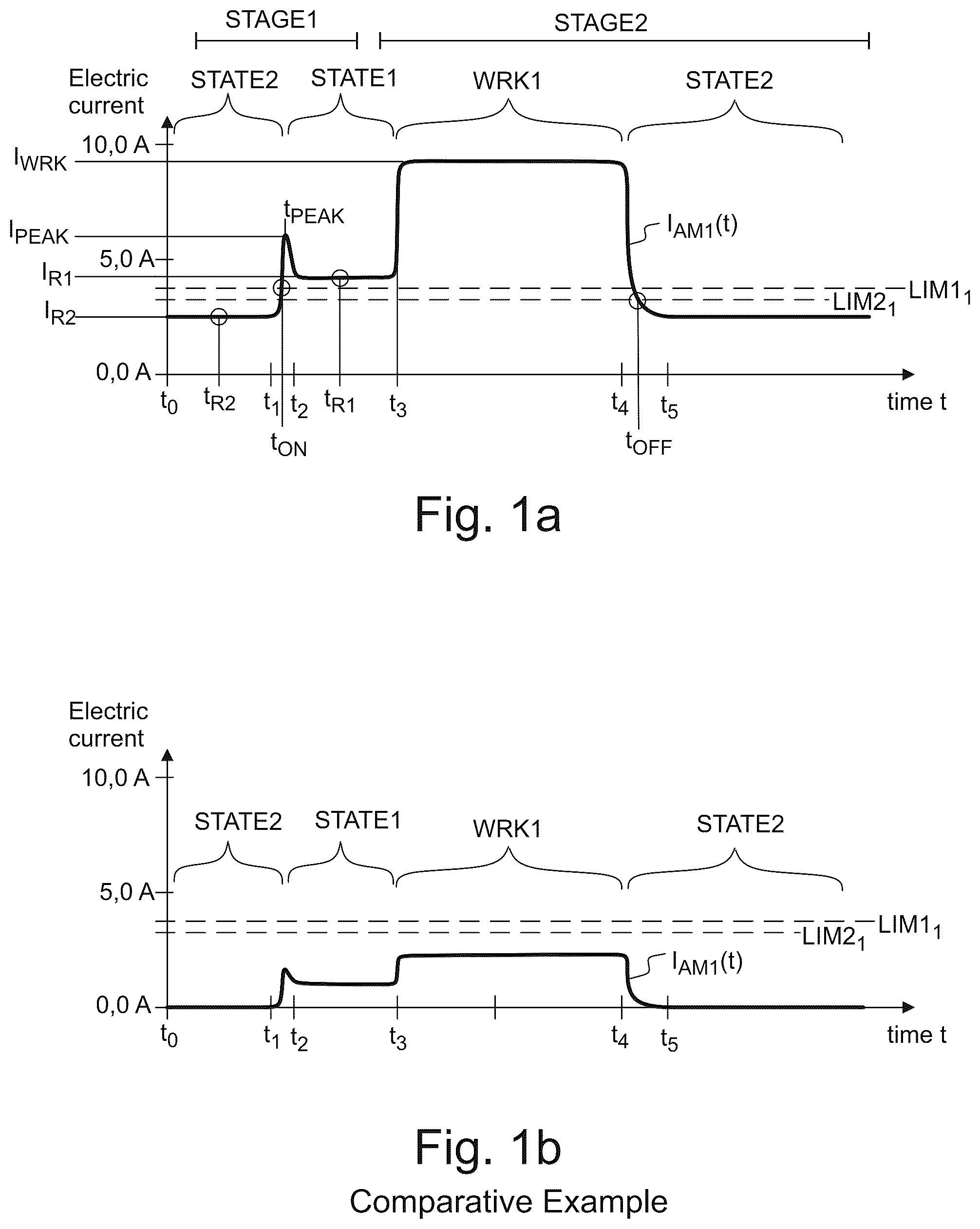
a shows, by way of example, temporal evolution of the measured electric current I AM1 (t) transferred from the electric outlet SOC 1 of the dust extractor 500 to a power tool TOOL 1 . The power tool TOOL 1 may have a motor MOTOR 2 e.g. as shown in a. The power tool TOOL 1 may have a first state STATE 1 , where the motor MOTOR 2 of the power tool TOOL 1 is running. The power tool TOOL 1 may be in a second state STATE 2 from the time t 0 to the time t 1 . The second state STATE 2 may be e.g. a standby state or a power off state. The second state STATE 2 may be e.g. a state where the motor of the power tool is not rotating. The power tool TOOL 1 may have a second state STATE 2 , where the motor MOTOR 2 of the power tool TOOL 1 is not running. Running of the motor MOTOR 2 of the power tool TOOL 1 may be started at a time t 1 . The rotation speed of the motor MOTOR 2 may be increased from the time t 1 to the time t 2 . The change of the rotation speed of the motor MOTOR 2 may cause a temporary peak I PEAK of the current at a time t PEAK . The power tool TOOL 1 may be in a first state STATE 1 from the time t 2 to the time t 3 . The first state STATE 1 may be e.g. a state where the motor of the power tool is rotating. The first state STATE 1 may be e.g. a no-load running state. The motor MOTOR 2 may run without a load during an idling time period from the time t 2 to the time t 3 . Processing of an object OBJ 1 with the power tool TOOL 1 may be started at a time t 3 . The power tool TOOL 1 may be used for processing an object OBJ 1 during a working time period WRK 1 from the time t 3 to the time t 4 . The power tool TOOL 1 may draw a current I WRK during the working time period WRK 1 , so as to provide mechanical power during the working time period WRK 1 . Running of the motor MOTOR 2 may be stopped at the time t 4 . Rotation of the motor MOTOR 2 may be stopped at the time t 5 . The power tool TOOL 1 may be in the second state STATE 2 after the time t 5 . Operation in the first state STATE 1 may involve generating dust particles DUST 1 and/or releasing previously generated dust particles. Operation in the first state STATE 1 may involve a risk of generating dust particles DUST 1 and/or a risk of releasing previously generated dust particles. Setting the power tool TOOL 1 to the second state STATE 2 may reduce or eliminate the risk of generating or releasing dust particles. The tool TOOL 1 may draw the electric current I AM1 (t) from the outlet SOC 1 of the dust extractor 500 . The electric current I AM1 (t) may depend on the state of the power tool TOOL 1 . The dust extractor 500 may be arranged to control the air flow rate Q AIR1 (t) of the dust extractor 500 based on the measured electric current I AM1 (t) of the outlet SOC 1 . For example, the dust extractor 500 may be arranged to start the air flow AIR 1 when the electric current I AM1 (t) increases to a first threshold value LIM 1 1 at a time t ON . For example, the dust extractor 500 may be arranged to stop the air flow AIR 1 when the electric current I AM1 (t) falls to a second threshold value LIM 2 1 at a time t OFF . The method may comprise a learning stage STAGE 1 , and a usage stage STAGE 2 . The threshold values LIM 1 , LIM 2 may be determined during the learning stage STAGE 1 . The air flow AIR 1 of the dust extractor 500 may be controlled based on the measured electric current I AM1 (t) during the usage stage STAGE 2 . The method may comprise measuring a first representative current value IR 1 when the power tool TOOL 1 is in the first state STATE 1 . The first representative current value IR 1 may be measured e.g. at a time t R1 , when the power tool TOOL 1 is operating in the first state STATE 1 . The first threshold value LIM 1 1 may be determined from the first representative current value I R1 . The first threshold value LIM 1 1 may be determined e.g. as a linear function of the first representative current value I R1 . For example, the first threshold value LIM 1 1 may be e.g. substantially equal to 50% of the first representative current value I R1 . For example, the first threshold value LIM 1 1 may be e.g. in the range of 30% to 70% of the first representative current value I R1 . The first threshold value LIM 1 1 may be smaller than the first representative current value I R1 . Consequently, operation of the tool TOOL 1 in the first state STATE 1 may cause an electric current I AM1 (t) which exceeds the first threshold value LIM 1 1 , so as to ensure reliable start of the air flow AIR 1 . The method may comprise measuring a second representative current value I R2 when the power tool TOOL 1 is in the second state STATE 2 . The second representative current value I R2 may be measured e.g. at a time t R2 , when the power tool TOOL 1 is in the second state STATE 2 . The first threshold value LIM 1 1 may be determined from the first representative current value I R1 and from the second representative current value I R2 . The first threshold value LIM 1 1 may be determined e.g. as a linear combination of the representative current values I R1 and I R2 . The first threshold value LIM 1 1 may be e.g. substantially equal to the average of the representative current values I R1 and IR 2 . The first threshold value LIM 1 1 may be greater than the second representative current value I R2 and smaller than the first representative current value I R1 . Consequently, operation of the tool TOOL 1 in the first state STATE 1 may cause electric current I AM1 (t) which exceeds the first threshold value LIM 1 1 , so as to ensure reliable start of the air flow AIR 1 , whereas the electric current I AM1 (t) of the stopped power tool TOOL 1 may be lower than the first threshold value LIM 1 1 so as to prevent starting the air flow AIR 1 in the second state STATE 2 . The dust extractor 500 may also be arranged to stop the air flow AIR 1 when the electric current I AM1 (t) falls to the second threshold value LIM 2 1 at a time t OFF . The second threshold value LIM 2 1 may be smaller than the first threshold value LIM 1 1 so as to provide hysteresis. The second threshold value LIM 2 1 may be smaller than the first threshold value LIM 1 1 and smaller than the first representative current value I R1 . The second threshold value LIM 2 1 may be determined e.g. as a linear combination of the representative current values I R1 and I R2 . The second threshold value LIM 2 1 may be smaller than the first threshold value LIM 1 1 , the second threshold value LIM 2 1 may be smaller than the first representative current value I R1 , and the second threshold value LIM 2 1 may be greater than the second representative current value I R2 . Consequently, the air flow AIR 1 may be reliably stopped when the power tool TOOL 1 is set to the second state STATE 2 . b shows, as a comparative example, electric current I AM1 (t) drawn by a second power tool TOOL 2 . The magnitude of the electric current I AM1 (t) of the second power tool TOOL 2 during the idling period (from time t 2 to t 3 ) is smaller than the electric current I AM1 (t) of the first power tool TOOL 1 of a during the corresponding idling period. In this comparative example, the electric current I AM1 (t) does not exceed the first threshold value LIM 1 1 , and the air flow of the dust extractor 500 remains stopped all the time. Referring to a , different threshold values LIM 1 2 , LIM 2 2 may be determined to ensure that air flow AIR 1 of the dust extractor 500 may be reliably controlled in case of the second power tool TOOL 2 . The second power tool TOOL 2 may be connected to the outlet SOC 1 of the dust extractor 500 after the first power tool TOOL 1 has been disconnected. New threshold values LIM 1 2 , LIM 2 2 may be determined during a new learning stage STAGE 1 to ensure reliable operation when using the second power tool TOOL 2 . A first threshold value LIM 1 2 may be determined from a first representative current value I R1 , which may be measured at a time t R1 when the power tool TOOL 2 is in the first state STATE 1 . A second representative current value I R2 may be measured e.g. at a time t R2 , when the power tool TOOL 2 is in the second state STATE 2 . The first threshold value LIM 1 2 may be determined from the first representative current value I R2 and from the second representative current value I R2 . During the usage stage STAGE 2 , the dust extractor 500 may be arranged to start the air flow AIR 1 when the electric current I AM1 (t) increases to the first threshold value LIM 1 2 at a time t ON . The dust extractor 500 may be arranged to stop the air flow AIR 1 when the electric current I AM1 (t) falls to the second threshold value LIM 2 2 at a time t OFF . The second threshold value LIM 2 2 may be smaller than or equal to the first threshold value LIM 1 2 . b shows, as a comparative example, the electric current I AM1 (t) of the first power tool TOOL 1 and the threshold values LIM 1 2 , LIM 2 2 of the second power tool TOOL 2 . The electric current I AM1 (t) of the first power tool TOOL 1 does not fall below the threshold value LIM 2 2 when the power tool is set to the second state STATE 2 . The air flow of the dust extractor is not properly stopped when the threshold values LIM 1 2 , LIM 2 2 are too low. Referring back to a , the threshold values LIM 1 1 , LIM 2 1 may be determined according to one or more measured electric current values of a power tool TOOL 1 , so as to ensure that the air flow AIR 1 of the dust extractor 500 may be properly controlled based on the measured electric current I AM1 (t) of the power tool TOOL 1 . a shows, by way of example, method steps for determining a first threshold value LIM 1 for controlling operation of the dust extractor, and method steps for controlling operation of the dust extractor by using the first threshold value LIM 1 . The power tool TOOL 1 may be electrically connected to the electric outlet SOC 1 of the dust extractor 500 . The learning stage STAGE 1 may be started e.g. by providing user input via the user interface of the dust extractor, or by connecting the power tool to the electric outlet of the dust extractor. The power tool TOOL 1 may be set to operate in the first state STATE 1 in step # 1210 . A first representative current value I R1 of the electric outlet SOC 1 may be measured when the power tool TOOL 1 is in the first state STATE 1 (step # 1212 ). The first representative current value I R1 may be associated with the first state STATE 1 based on first user input INPUT 1 (step # 1214 ). In an embodiment, the steps # 1212 and # 1214 may be performed at the same time. For example, the control system SYS 1 may measure the first representative current value I R1 at a time t R1 when the control system SYS 1 receives user input INPUT 1 via the user interface UIF 1 , wherein receipt of said user input INPUT 1 may also associate said measured first representative current value I R1 with the first state STATE 1 . For example, the method may comprise: asking the user to press a button of the user interface when the power tool is in the first state, pressing the button when the power tool is in the first state, measuring the first representative current value when the button is pressed, and associating the first representative current value with the first state based on the pressing of the button. The user may confirm by pressing the button of the user interface that the power tool is in the first state so that the first representative current value I R1 measured at the time t R1 may be associated with the first state STATE 1 . The button is mentioned as an example. The user input(s) may also be provided via one or more other input devices, instead or in addition to the button(s). The measured first representative current value I R1 may be associated with the state STATE 1 based on user input INPUT 1 received when the power tool TOOL 1 is in the first state STATE 1 . The first threshold value LIM 1 for starting the air flow AIR 1 may be determined from the first representative current value I R1 in step # 1250 . A second threshold value LIM 2 for stopping the air flow AIR 1 may be determined. The second threshold value LIM 2 may be equal to or smaller than the first threshold value LIM 1 . The second threshold value LIM 2 may be smaller than the first threshold value LIM 1 in order to provide hysteresis. The determined threshold values LIM 1 , LIM 2 may be stored in a memory (e.g. MEM 3 ). After the threshold value LIM 1 or threshold values LIM 1 , LIM 2 have been determined and stored in the memory, then the operation of the dust extractor 500 may be controlled based on the measured electric current I AM1 (t) of the power tool TOOL 1 . The learning stage STAGE 1 may be stopped and/or the usage stage STAGE 2 may be started after the threshold values LIM 1 , LIM 2 have been determined. The learning stage STAGE 1 may be stopped and/or the usage stage STAGE 2 may be started based on user input (e.g. INPUT 1 or INPUT 2 ). The electric current I AM1 (t) of the power tool TOOL 1 may be measured intermittently or continuously in step # 1300 . The measured electric current I AM1 (t) may be compared with the first threshold value LIM 1 in step # 1310 . The air flow AIR 1 of the dust extractor 500 may be controlled based on the result of the comparison. The air flow AIR 1 of the dust extractor 500 may be started if the measured electric current I AM1 (t) increases to or exceeds the first threshold value LIM 1 in step # 1315 . The measured electric current I AM1 (t) may be compared with the second threshold value LIM 2 in step # 1320 . The air flow AIR 1 of the dust extractor 500 may be controlled based on the result of the comparison. The air flow AIR 1 of the dust extractor 500 may be stopped if the measured electric current I AM1 (t) falls to or below the second threshold value LIM 2 in step # 1325 . The operation of the dust extractor 500 may be controlled e.g. by repeating the steps # 1300 to # 1325 . In an embodiment, the control system SYS 1 of the dust extractor 500 may detect when the connector PLUG 1 of the power tool TOOL 1 is separated from the electric outlet SOC 1 of the dust extractor 500 . For example, the control system SYS 1 may comprise a sensor for detecting whether a connector PLUG 1 is in connection with the outlet SOC 1 or not. The sensor may be e.g. a mechanical, optical, capacitive or inductive sensor. In an embodiment, the control system SYS 1 may start to operate in a default operating mode after the control system SYS 1 detects that the connector PLUG 1 has been separated from the electric outlet SOC 1 . In the default operating mode, the first threshold value LIM 1 may be set to a default value. The first threshold value LIM 1 may be equal to the default value until a different value is determined e.g. by the steps # 1210 to # 1250 . b shows, by way of example, method steps for determining a first threshold value LIM 1 for controlling operation of the dust extractor, and method steps for controlling operation of the dust extractor by using the first threshold value LIM 1 . In addition to the method steps shown in a , the method of 3 b may comprise method steps # 1220 , # 1222 , # 1224 for setting the power tool TOOL 1 to a second state STATE 2 , measuring a second representative current value I R2 , and associating the second representative current value I R2 with the second state STATE 2 . The motor MOTOR 2 of the power tool TOOL 1 may rotate in the first state STATE 1 . The motor MOTOR 2 of the power tool TOOL 1 may be stopped in the second state STATE 2 . The second state STATE 2 may be e.g. a standby state or a power off state. The power tool TOOL 1 may be set to operate in the first state STATE 1 in step # 1210 . A first representative current value I R1 of the electric outlet SOC 1 may be measured when the power tool TOOL 1 is in the first state STATE 1 (step # 1212 ). The first representative current value I R1 may be associated with the first state STATE 1 based on first user input INPUT 1 (step # 1214 ). In an embodiment, the steps # 1212 and # 1214 may be performed at the same time. For example, the control system SYS 1 may measure the first representative current value I R1 at a time t R1 when the control system SYS 1 receives user input INPUT 1 via the user interface UIF 1 , wherein receipt of said user input INPUT 1 may also associate said measured first representative current value I R1 with the first state STATE 1 . The power tool TOOL 1 may be set to operate in the second state STATE 2 in step # 1220 . A second representative current value I R2 of the electric outlet SOC 1 may be measured when the power tool TOOL 1 is in the second state STATE 2 (step # 1222 ). The second representative current value I R2 may be associated with the second state STATE 2 based on second user input INPUT 2 (step # 1224 ). For example, the method may comprise: asking the user to press a button of the user interface when the power tool is in the second state, pressing the button when the power tool is in the second state, measuring the second representative current value when the button is pressed, and associating the second representative current value with the second state based on the pressing of the button. The steps # 1220 to # 1224 may be performed e.g. before or after the steps # 1210 to # 1214 . After the threshold value LIM 1 or threshold values LIM 1 , LIM 2 have been determined and stored in the memory, then the operation of the dust extractor 500 may be controlled based on the measured electric current I AM1 (t) of the power tool TOOL 1 . The learning stage STAGE 1 may be stopped and/or the usage stage STAGE 2 may be started based on user input (e.g. INPUT 1 or INPUT 2 ). The operation of the dust extractor 500 may be controlled e.g. by repeating the steps # 1300 to # 1325 . a shows, by way of example, an apparatus 1000 , which comprises a power tool TOOL 1 (or TOOL 2 ) and a dust extractor 500 . The apparatus 1000 may be e.g. a surface processing apparatus. The dust extractor 500 may comprise a rotating suction fan FAN 1 to cause a partial vacuum (p 1 ), which in turn may draw an air flow AIR 1 through a hose HOSE 1 connected to the dust extractor 500 . The fan FAN 1 may be e.g. an axial fan and/or a centrifugal fan. The dust extractor 500 may comprise a motor MOTOR 1 for rotating the suction fan FAN 1 . The air flow AIR 1 may be started by starting rotation of the fan FAN 1 . The air flow AIR 1 may be stopped by stopping rotation of the fan FAN 1 . Increasing the rotation speed of the motor MOTOR 1 and the fan FAN 1 may cause a lower inner pressure p 1 , thereby increasing the air flow rate Q AIR1 through the hose HOSE 1 and through the suction fan FAN 1 . Decreasing the rotation speed of the motor MOTOR 1 may cause a higher inner pressure p 1 , thereby decreasing the air flow rate Q AIR1 . The dust extractor 500 may be arranged to suck dust particles DUST 1 carried by the suction air flow AIR 1 . The dust extractor 500 may also be called e.g. as a vacuum cleaner. The dust extractor 500 may comprise a particle separator FIL 1 to separate dust particles DUST 1 from the air flow AIR 1 . The particle separator FIL 1 may comprise e.g. a filter and/or a cyclone. The particle separator FIL 1 may collect the separated dust particles DUST 1 . The suction fan FAN 1 may draw the air flow AIR 1 through the particle separator FIL 1 . The apparatus 1000 may comprise a flexible hose HOSE 1 connected to the dust extractor 500 . The hose HOSE 1 may convey an air flow AIR 1 and dust particles DUST 1 to the dust extractor 500 . The hose HOSE 1 may convey an air flow AIR 1 and dust particles DUST 1 e.g. from a working area of a power tool TOOL 1 to the dust extractor 500 . The power tool TOOL 1 may be e.g. a sander, a drilling machine, or a sawing machine. The apparatus 1000 may be e.g. a surface processing apparatus. The surface processing apparatus 1000 may comprise a power tool TOOL 1 for processing a surface SRF 1 of an object OBJ 1 . The power tool TOOL 1 may be e.g. a rotary sander, an orbital sander or a belt sander. The dust extractor 500 comprises an air inlet IN 1 for the suction air flow AIR 1 . The dust extractor 500 may be arranged to draw the dust-laden air flow AIR 1 via the openings OP 1 and via the hose HOSE 1 to the inlet IN 1 . The suction hose HOSE 1 may be detachably connectable to the inlet IN 1 . The hose HOSE 1 may be connected to the inlet IN 1 e.g. by using an adapter connector ADA 1 . The dust extractor 500 has an air outlet OUT 1 for discharging the air flow AIR 1 to the surroundings, after the dust particles DUST 1 carried by the air flow AIR 1 have been separated from the air flow AIR 1 . p 0 denotes the ambient atmospheric pressure. Pressure near the power tool TOOL 1 and at the air outlet OUT 1 of the dust extractor 500 may be substantially equal to the atmospheric pressure p 0 . The ambient pressure p 0 is typically substantially equal to 101.3 kPa. p CHM1 denotes an internal pressure of the inlet chamber CHM 1 of the dust extractor 500 . The pressure p CHM1 may also denote the upstream pressure of the particle separator FIL 1 (e.g. filter). The pressure difference p 0 -p CHM1 may draw the dust-laded air flow AIR 1 from the abrasive article ABR 1 to the inlet chamber CHM 1 of the dust extractor 500 via the hose HOSE 1 . The rotating fan FAN 1 may cause the partial vacuum p 1 , which prevails between the particle separator FIL 1 and the fan FAN 1 . p 1 denotes an upstream pressure of the fan FAN 1 and downstream pressure of the particle separator FIL 1 . The pressure p 1 may be the lowest pressure of the apparatus 1000 . p 2 denotes a downstream pressure of the fan FAN 1 . The maximum pressure difference (p 2 −p 1 ) over the fan FAN 1 may be e.g. in the range of 5 to 30 kPa. The dust extractor device 500 may comprise a dust chamber CHM 1 for guiding the dust-laded airflow AIR 1 from the inlet IN 1 to the dust separator FIL 1 and/or for collecting the separated dust DUST 1 . The dust extractor device 500 may comprise an air flow chamber CHM 2 for guiding the air flow AIR 1 from the fan FAN 1 to the air outlet OUT 1 . The dust extractor 500 comprises an electric outlet SOC 1 connectable to a power tool TOOL 1 , TOOL 2 . An electric cable CBL 1 of the power tool TOOL 1 may be connected to the electric outlet SOC 1 of the dust extractor 500 . Operation of the power tool TOOL 1 may generate dust particles DUST 1 . The dust extractor 500 may be arranged to remove the generated dust particles DUST 1 via a hose HOSE 1 . The power tool TOOL 1 may be arranged to process a surface SRF 1 of an object OBJ 1 . The apparatus 1000 may be e.g. a surface processing apparatus 1000 . The power tool TOOL 1 may be e.g. a sanding machine, e.g. an orbital sanding machine. The control system SYS 1 of the dust extractor 500 may comprise a current meter unit AM 1 to measure an electric current I AM1 (t) drawn by the power tool TOOL 1 via the electric outlet SOC 1 . The current meter unit AM 1 may measure one or more electric currents I AM1 (t) transmitted via the electric outlet SOC 1 . The control system SYS 1 may comprise a user interface UIF 1 for receiving user input from a user and/or for providing information to the user. The control system SYS 1 may comprise a user interface UIF 1 for receiving user input INPUT 1 , INPUT 2 . The control system SYS 1 may be arranged to associate the first measured representative current value I R1 with the first state STATE 1 based on first user input INPUT 1 . The control system SYS 1 may be arranged to associate the second measured representative current value I R2 with the second state STATE 2 based on second user input INPUT 2 . The control system SYS 1 may be arranged to determine threshold values LIM 1 , LIM 2 from the measured representative current values I R1 , I R2 . The control unit CNT 1 may be arranged to determine threshold values LIM 1 , LIM 2 from the measured representative current values I R1 , I R2 . The control system SYS 1 may comprise a memory MEM 3 for storing the determined threshold values LIM 1 , LIM 2 . The control system SYS 1 may control operation of the dust extractor 500 based on the measured electric current I AM1 (t). The control system SYS 1 may compare the measured electric current I AM1 (t) with the threshold values LIM 1 , LIM 2 . The control system SYS 1 may start and/or stop the air flow AIR 1 based on a result of the comparison. The dust extractor 500 may comprise a control unit CNT 1 for controlling operation of the motor MOTOR 1 based on measured electric current I AM1 (t) of the electric outlet SOC 1 . The motor MOTOR 1 may be e.g. an asynchronous or synchronous electric motor. The motor MOTOR 1 may be e.g. an alternating current motor or a direct current motor. The motor MOTOR 1 may be e.g. an universal motor. The motor MOTOR 1 may be e.g. brushless direct current motor. The control system SYS 1 may comprise a motor driving unit MDU 1 for driving the motor MOTOR 1 according to a motor control signal S MOTOR1 . The motor driving unit MDU 1 may provide one or more electric currents EC 1 to the motor MOTOR 1 according to the motor control signal S MOTOR1 . The motor driving unit MDU 1 may comprise e.g. one or more electromechanical relays, thyristors and/or transistors for controlling one or more operating currents of the motor MOTOR 1 . The motor driving unit MDU 1 may comprise e.g. power transistors and/or thyristors for providing the electric currents EC 1 for the motor MOTOR 1 . In an embodiment, the motor driving unit MDU 1 may comprise a frequency converter for reducing or increasing the rotation speed of the motor MOTOR 1 . The motor driving unit MDU 1 may provide one or more electric currents EC 1 in response to the motor control signal S MOTOR1 . The control unit CNT 1 may form the motor control signal S MOTOR1 based on the measured electric current I AM1 (t). The control system SYS 1 may form the motor control signal S MOTOR1 for the motor driving unit MDU 1 . The motor driving unit MDU 1 may start or stop rotation of the motor MOTOR 1 based on the motor control signal S MOTOR1 . The motor driving unit MDU 1 may reduce or increase air flow rate Q AIR1 (t) of the dust extractor 500 based on the motor control signal S MOTOR1 . The electrical system of the dust extractor 500 may receive electric operating power from a mains network MAINS 1 via two or more nodes N 1 , N 0 . The nodes N 0 , N 1 may be connected to the AC mains network MAINS 1 . AC means alternating current. The voltage and the frequency of the network MAINS 1 may be e.g. 230 V at 50 Hz or 110 V at 60 Hz. The electric power may be distributed from the nodes N 1 , N 0 to the electric outlet SOC 1 and to the motor driving unit MDU 1 . The electric power may be distributed from the nodes N 1 , N 0 to the electric outlet SOC 1 via conductors W 1 , W 0 . The current metering unit AM 1 may be arranged to measure the current I AM1 (t) of the first conductor W 1 and/or the current of the second conductor W 2 . During normal operation, the current I AM1 (t) of the first conductor W 1 may be equal to the current I AM0 (t) of the second conductor W 0 . The electric outlet SOC 1 may be e.g. a socket according to the standard CEE 7/3, which is also known as the “Schuko” socket. The standard CEE 7/3 has been determined by the International Commission on the Rules for the Approval of Electrical Equipment (IECEE). Sockets according to CEE 7/3 are widely in use e.g. in Germany. The electric outlet SOC 1 may be e.g. a socket according to the standard NEMA 5-15 grounded (Type B). The standard NEMA has been determined by the National Electrical Contractors Association (NECA). Sockets according to the standard NEMA 5-15 grounded (Type B) are widely in use e.g. in the USA. The RMS voltage level V 1 (t) of the outlet SOC may be e.g. in the range of 100 V to 240 V. The RMS voltage level V 1 (t) of the outlet SOC may be substantially equal to the voltage of the mains network MAINS 1 . The first power tool TOOL 1 may be initially connected to the electric outlet SOC 1 . The threshold values LIM 1 , LIM 2 may be determined from the representative current values I R1 , I R2 associated with the states STATE 1 , STATE 2 , e.g. as shown in a or 3 b . The first power tool TOOL 1 may be used for processing the object OBJ 1 . The control system SYS 1 may start the air flow AIR 1 based on the measured current I AM1 (t) when the first power tool TOOL 1 starts to operate in the first state STATE 1 . The control system SYS 1 may stop the air flow AIR 1 based on the measured current I AM1 (t) when the first power tool TOOL 1 is set into the second state STATE 2 (standby). Next, the first power tool TOOL 1 may be disconnected from the electric outlet SOC 1 , and a second power tool TOOL 2 may be connected to the electric outlet SOC 1 . New threshold values LIM 1 , LIM 2 may subsequently be determined from the representative current values associated with the states, e.g. as shown in a or 3 b . The second power tool TOOL 2 may be used for processing the object OBJ 1 or another object. The control system SYS 1 may start the air flow AIR 1 based on the measured current I AM1 (t) when the second power tool TOOL 2 starts to operate in the first state STATE 1 . The control system SYS 1 may stop the air flow AIR 1 based on the measured current I AM1 (t) when the second power tool TOOL 2 is set into the second state STATE 2 (standby). Controlling operation of the dust extractor 500 based on the measured current I AM1 (t) may save energy, may reduce cumulative dose of noise, may reduce noise level in the second state STATE 2 , and/or may increase operating lifetime of the dust extractor 500 . Referring to b , the power tool TOOL 1 , TOOL 2 may comprise an electric motor MOTOR 2 for causing relative movement of a processing element ABR 1 with respect to an object OBJ 1 . The motor MOTOR 2 and other components of the power tool TOOL 1 , TOOL 2 may be powered by the electric current I AM1 (t) received from the outlet SOC 1 via a cable CBL 1 . The cable CBL 1 may comprise an electric connector PLUG 1 connectable to the outlet SOC 1 of the dust extractor 500 . The power tool TOOL 1 , TOOL 2 may be used for processing the object OBJ 1 . The apparatus 1000 may be a processing apparatus. The power tool may be used for processing a surface SRF 1 of the object OBJ 1 . The apparatus 1000 may be a surface processing apparatus. For example, the power tool TOOL 1 may comprise an abrasive article ABR 1 , which comprises abrasive grains. The tool TOOL 1 may comprise a supporting pad PAD 1 . The abrasive article ABR 1 may be attached to the pad PAD 1 . The tool TOOL 1 may comprise a motor MOTOR 2 for causing a movement of the abrasive article ABR 1 with respect to the surface SRF 1 . The tool TOOL 1 may comprise a motor MOTOR 2 for causing rotary and/or oscillatory movement of the abrasive article ABR 1 with respect to the surface SRF 1 . Pressing the abrasive article ABR 1 against the surface SRF 1 may generate dust particles DUST 1 , which may comprise particles released from the surface SRF 1 and/or particles released from the abrasive article ABR 1 . The tool TOOL 1 may comprise one or more openings OP 1 for extracting released particles DUST 1 together with an air flow AIR 1 . The power tool TOOL 1 , TOOL 2 may comprise one or more openings OP 1 for the suction air flow AIR 1 . The power tool may comprise an outlet port PORT 1 connectable to a hose HOSE 1 . Dust particles DUST 1 carried by the air flow AIR 1 may be sucked via the openings OP 1 , via the outlet port PORT 1 , and via a hose HOSE 1 to the dust extractor 500 . The power tool TOOL 1 , TOOL 2 may be e.g. a sander or a grinding device. The processing element ABR 1 may be e.g. an abrading element, which comprises a plurality of abrasive grains. The power tool TOOL 1 , TOOL 2 may have at least one operating state STATE 1 , which has a considerable risk of generating dust DUST 1 . The power tool TOOL 1 , TOOL 2 may be e.g. a sander device, a grinding device, tile cutter, a milling machine, a router, a saw, a rotary saw, a bandsaw, an oscillating saw, a drill. The power tool may comprise a user interface UIF 2 for receiving user input and/or for providing information to the user. The power tool may comprise a control unit CNT 2 for controlling operation of the power tool based on user input received via the user interface UIF 2 . For example, the control unit CNT 2 may start rotation of the motor MOTOR 2 when a user input is provided by pressing a button of the user interface UIF 2 . For example, the control unit CNT 2 may stop rotation of the motor MOTOR 2 when the user stops pressing the button of the user interface UIF 2 . For example, the control unit CNT 2 may be energized all the time when the power tool is connected to the mains network MAINS 1 via the outlet SOC 1 of the dust extractor 500 . Referring to c , the dust extractor 500 may comprise the suction air inlet AIR 1 , the electric outlet SOC 1 for the power tools, the air outlet OUT 1 , and user interface devices UIF 1 a , UIF 1 b , UIF 1 c , UIF 1 d. The user interface UIF 1 may comprise e.g. input devices UIF 1 a , UIF 1 b , UIF 1 c and/or an output device UIF 1 d. The user interface UIF 1 may comprise an input device UIF 1 a for inputting a power setting of the motor MOTOR 1 . The input device UIF 1 a may be implemented e.g. by a rotary handle, by a sliding handle, and/or by one or push buttons. A user may manually move the handle so as to select a target power setting of the motor MOTOR 1 . The input device UIF 1 a may provide the selected target power level as an input to the control system SYS 1 . The user interface UIF 1 may comprise an input device UIF 1 b for setting an operating mode of the dust extractor 500 . For example, the dust extractor 500 may have a first operating mode where the dust extractor 500 operates only when electric power is drawn from the outlet SOC 1 . The auto start functionality of the dust extractor may be enabled in the first operating mode. The dust extractor 500 may have a second operating mode where the dust extractor 500 operates continuously. The auto start functionality of the dust extractor may be disabled in the second operating mode. The dust extractor 500 may have a first operating mode where the air flow AIR 1 is controlled according to the measured electric current I AM1 (t) of the outlet SOC 1 . The dust extractor 500 may have a second operating mode where the air flow AIR 1 is independent of the measured electric current I AM1 (t) of the outlet SOC 1 . The input device UIF 1 b may be implemented e.g. by a rotary handle, by a sliding handle, and/or by one or push buttons. The user interface UIF 1 may comprise an input device UIF 1 c for associating a measured current value with a state (STATE 1 ) of a power tool TOOL 1 . The input device UIF 1 c may comprise e.g. one or more push buttons. The button is mentioned as an example. One or more other input devices may be used instead of or in addition to the button. The input device may be e.g. a touchscreen. The user interface UIF 1 may comprise an output device UIF 1 d for providing information to a user. The output device UIF 1 d may comprise e.g. a one or more indicator lights to indicate when the user is expected to provide the user input INPUT 1 and/or INPUT 2 . The output device UIF 1 d may comprise e.g. a display to indicate when the user is expected to provide the user input INPUT 1 and/or INPUT 2 . For example, the output device UIF 1 d may provide a visual prompt and/or an audible prompt for the user. The indicator light is mentioned as an example. One or more other output device may be used instead of or in addition to the indicator light(s). The output device may be e.g. a display, in particular a touchscreen. SX, SY, and SZ denote orthogonal directions. shows, by way of example, the control system SYS 1 of the dust extractor 500 . The control system SYS 1 may comprise the control unit CNT 1 , a current measuring unit AM 1 , a user interface UIF 1 , and a motor driving unit MDU 1 . The current measuring unit AM 1 may form a current indicator signal S AM1 indicative of the measured electric current I AM1 (t) of the outlet SOC 1 . During the learning stage STAGE 1 , the current measuring unit AM 1 may measure the representative current values I R1 , I R2 for determining the threshold values LIM 1 , LIM 2 . During the usage stage STAGE 2 , the current measuring unit AM 1 may continuously or intermittently measure the electric current I AM1 (t) of the outlet SOC 1 for controlling the air flow AIR 1 based on the electric current I AM1 (t). The control unit CNT 1 may receive the current indicator signal S AM1 . The control unit CNT 1 may control the air flow AIR 1 based on the measured current I AM1 (t). The control unit CNT 1 may form a motor control signal S MOTOR1 based on the measured current I AM1 (t), so as to control the air flow AIR 1 . The motor driving unit MDU 1 may drive the motor MOTOR 1 of the dust extractor 500 by forming one or more electric driving currents EC 1 . The motor driving unit MDU 1 may form the electric driving currents EC 1 from electric power received via the nodes N 0 , N 1 . The motor driving unit MDU 1 may form the electric driving currents EC 1 according to the motor control signal S MOTOR1 formed by the control unit CNT 1 . The motor driving unit MDU 1 may comprise e.g. a relay to switch on and off one or more driving currents EC 1 of the motor MOTOR 1 . The motor driving unit MDU 1 may be arranged to adjust one or more driving currents EC 1 by pulse width modulation or by phase fired control. The motor driving unit MDU 1 may comprise e.g. a frequency converter to adjust the frequency of one or more driving currents EC 1 . The user interface UIF 1 may comprise one or more input devices UIF 1 a , UIF 1 b , UIF 1 c . The user interface UIF 1 may comprise one or more output devices UIF 1 d . The user interface UIF 1 may be arranged to receive user input INPUT 1 , INPUT 2 from a user to the control unit CNT 1 . The dust extractor 500 may receive electric power from the mains network via two or more nodes N 0 , N 1 . The electric power may be distributed from the nodes N 0 , N 1 to the outlet SOC 1 and to the motor driving unit MDU 1 . The electric power may be distributed from the nodes N 0 , N 1 to the motor driving unit MDU 1 e.g. via conductors W 3 , W 4 . The outlet SOC 1 may comprise two or more connectors CON 1 , CON 1 to form a galvanic contact with the conductors of the cable CBL 1 of the power tool TOOL 1 , TOOL 2 . A first electric current I AM1 (t) may be transmitted from the first node N 1 to a first connector CON 1 of the outlet SOC 1 via a first conductor W 1 . A second electric current I AM0 (t) may be transmitted from the second node N 0 to a second connector CON 0 of the outlet SOC 1 via a second conductor W 0 . The current metering unit AM 1 may measure the first electric current I AM1 (t) and/or the second electric current I AM0 (t). The current metering unit AM 1 may form a current indicator signal S AM1 indicative of the measured electric current I AM1 (t). The sum of the electric currents may be equal to zero during normal operation, i.e. I AM1 (t)+I AM0 (t)=0. The control system SYS 1 may be arranged start operation in a learning stage STAGE 1 e.g. based on user input received via the user interface UIF 1 and/or when the dust extractor 500 is connected to the mains network MAINS 1 . The threshold values LIM 1 , LIM 2 may be determined in the learning stage STAGE 1 The output device UIF 1 d may be arranged to provide a first prompt PROMPT 1 for the user to indicate when the control system SYS 1 is ready to receive first user input INPUT 1 . For example, the first prompt PROMPT 1 may contain a message “press the button when the tool is in the first state”. The input device UIF 1 c may be arranged to receive the user input INPUT 1 for associating a measured representative current value I R1 with the first state STATE 1 of the power tool TOOL 1 , TOOL 2 . For example, the input device UIF 1 c may comprise one or more push buttons. The current measuring unit AM 1 may measure the first representative current value I R1 in a situation where the power tool TOOL 1 operating in the first state STATE 1 is connected to the outlet SOC 1 . The control system SYS 1 of the dust extractor 500 may associate the measured representative current value I R1 with the first state STATE 1 e.g. when the user provides user input INPUT 1 via the input device UIF 1 c during operation in the first state STATE 1 . The control system SYS 1 may associate the measured representative current value I R1 with the first state STATE 1 e.g. when the user pushes a button of the input device UIF 1 c during operation in the first state STATE 1 . The output device UIF 1 d may be arranged to provide a second prompt PROMPT 2 for the user to indicate when the control system SYS 1 is ready to receive the second user input INPUT 2 . For example, the second prompt PROMPT 2 may indicate or contain a message “press the button when the tool is in the second state”. The input device UIF 1 c may be arranged to receive user input INPUT 2 for associating a measured representative current value I R2 with the second state STATE 2 of the power tool TOOL 1 , TOOL 2 . For example, the input device UIF 1 c may comprise one or more push buttons. The current measuring unit AM 1 may measure an electric current value I R2 in a situation where the power tool TOOL 1 connected to the outlet SOC 1 is in the second state STATE 2 . The control system SYS 1 of the dust extractor 500 may associate the measured representative current value I R2 with the second state STATE 2 e.g. when the user provides user input INPUT 2 via the input device UIF 1 c . The control system SYS 1 may associate the measured representative current value I R1 with the first state STATE 1 e.g. when the user pushes a button of the input device UIF 1 c during operation in the first state STATE 1 . The user interface UIF 1 may comprise an input device UIF 1 a for setting a target power of the motor MOTOR 1 (e.g. low power, medium power, high power). The input device UIF 1 a may be implemented e.g. by a rotary handle, by a sliding handle, and/or by one or push buttons. The user interface UIF 1 may comprise an input device UIF 1 b for setting an operating mode of the dust extractor 500 . The input device UIF 1 b may be implemented e.g. by a rotary handle, by a sliding handle, and/or by one or push buttons. In an embodiment, the dust extractor 500 may comprise e.g. a keypad or a touch screen for receiving user input. The control unit CNT 1 may be implemented e.g. by one or more data processors. The control system SYS 1 may comprise a machine-readable memory MEM 1 for storing computer program code PRG 1 . The control unit CNT 1 may be implemented e.g. by executing program code PRG 1 by one or more data processors of the control system SYS 1 . The program code PRG 1 , when executed by one or more processors of the control unit CNT 1 may cause the control unit CNT 1 to determine threshold values (LIM 1 , LIM 2 ) and/or to control the air flow based on the measured electric current. The control system SYS 1 may comprise a machine-readable memory MEM 2 for storing operating parameters PAR 1 of the extractor device 500 . The operating parameters PAR 1 may specify e.g. a time delay between initiating a stopping of the air flow, and stopping operation of the motor MOTOR 1 . The control system SYS 1 may comprise a machine-readable memory MEM 3 for storing determined threshold values LIM 1 , LIM 2 . The control system SYS 1 may comprise a communication unit RXTX 1 for enabling communication with one or more external devices. The communication unit RXTX 1 may enable communication e.g. via Bluetooth, wireless local area network, and/or wireless mobile communications network. For example, the communication unit RXTX 1 may enable communication with a mobile phone. In an embodiment, the user interface UIF 1 of the control system SYS 1 may be implemented by using a mobile phone. The control system SYS 1 may be arranged to receive user input INPUT 1 , INPUT 2 from a mobile phone via the communication unit RXTX 1 . The user interface UIF 1 (UIF 1 a , UIF 1 b , UIF 1 c , UIF 1 d ) may be implemented e.g. by an application running on a mobile phone. The (mobile) user interface UIF 1 may communicate with the dust extractor 500 e.g. via wireless communication. The (mobile) user interface UIF 1 may communicate with the dust extractor 500 e.g. via the communication unit RXTX 1 . In an embodiment, the method may comprise changing the state of the power tool TOOL 1 between a first state STATE 1 and a second state STATE 2 during the learning stage STAGE 1 , and the control system SYS 1 may continuously or intermittently record the electric current I AM1 (t) during the learning stage STAGE 1 . The user may stop the learning stage STAGE 1 by providing user input (INPUT 1 ) via the user interface UIF 1 . The control system SYS 1 may be configured to determine that the first representative current value I R1 is equal to the maximum stable current value measured during the learning stage STAGE 1 , and to determine that the second representative current value I R2 is equal to the minimum stable current value measured during the learning stage STAGE 1 . The user input (INPUT 1 ) defines the end of the learning stage STAGE 1 , which comprises a time period where the power tool TOOL 1 is in the first state STATE 1 . Thus, the control system SYS 1 may associate the first representative current value I R1 with the first state STATE 1 based on the user input (INPUT 1 ). In an embodiment, the dust extractor 500 may be arranged to operate such that the air flow AIR 1 is not completely stopped when the power tool TOOL 1 is in the second state STATE 2 , e.g. in order to reduce risk of releasing of harmful dust particles DUST 1 to the environment. The air flow rate Q AIR1 (t) of the dust extractor 500 may be e.g. in the range of 1% to 30% of the maximum air flow rate Q AIR1 (t) of the dust extractor 500 , in a situation where power tool is in the second state STATE 2 . In an embodiment, the control system SYS 1 may optionally comprise a voltage measuring unit VM 1 to measure the voltage V 1 (t) of the node N 1 . The voltage measuring unit VM 1 to measure the voltage difference V 1 (t) between the nodes N 0 , N 1 . The voltage measuring unit VM 1 may form a voltage indicator signal S V1 indicative of the measured voltage V 1 (t). In an embodiment, the control system SYS 1 may be arranged to calculate RMS electric power transmitted via the electric outlet SOC 1 from the measured current I AM1 (t) and from the measured voltage V 1 (t). RMS means root mean square. For the person skilled in the art, it will be clear that modifications and variations of the devices and methods according to the present invention are perceivable. The figures are schematic. The particular embodiments described above with reference to the accompanying drawings are illustrative only and not meant to limit the scope of the invention, which is defined by the appended claims.
Figures (7)
Citations
This patent cites (9)
- US2010/0154161
- US2019/0030669
- US2021/0100417
- US2021/0353121
- US2433543
- US3009058
- US4936226
- US2019/081118
- US2021096409