Wedge Bonding Tools and Methods of Forming Wire Bonds
Abstract
A wedge bonding tool is provided. The wedge bonding tool includes a body portion including a tip portion, the tip portion terminating at a working end of the wedge bonding tool. The tip portion includes (i) two opposing walls, and (ii) an adjoining surface between the two opposing walls. The adjoining surface includes a flat area. The two opposing walls and the flat area define a groove configured to receive a wire. The flat area has a width of at least 20% of a width of the groove at the working end.
Claims (16)
1 . A wedge bonding tool comprising: a body portion including a tip portion, the tip portion terminating at a working end of the wedge bonding tool, the tip portion including (i) two opposing walls, and (ii) an adjoining surface between the two opposing walls, the adjoining surface including a flat area, the two opposing walls and the adjoining surface defining a recess surrounding the flat area, the recess exceeding a width of the adjoining surface such that the two opposing walls define part of the recess, the two opposing walls and the flat area defining a groove configured to receive a wire, the flat area having a width of at least 20% of a width of the groove at the working end.
9 . A wedge bonding tool comprising: a body portion including a tip portion, the tip portion terminating at a working end of the wedge bonding tool, the tip portion including (i) two opposing walls, and (ii) an adjoining surface between the two opposing walls, the adjoining surface including a flat area which extends along both x-axis and y-axis, the adjoining surface defining a recess, the recess bisecting the flat area and extending into each of the two opposing walls such that a portion of the recess is defined by each of the two opposing walls, the two opposing walls and the flat area defining a groove configured to receive a wire, the flat area having a width of at least 20% of a width of the groove at the working end.
Show 14 dependent claims
2 . The wedge bonding tool of claim 1 wherein at least one protrusion extends from the flat area.
3 . The wedge bonding tool of claim 1 wherein a plurality of protrusions extends from the flat area.
4 . The wedge bonding tool of claim 3 wherein each of the plurality of protrusions includes a quadrilateral shape.
5 . The wedge bonding tool of claim 1 wherein the adjoining surface includes a concave portion adjacent the flat area, the concave portion being on a feed side of the wedge bonding tool.
6 . The wedge bonding tool of claim 1 wherein the flat area is rectangular.
7 . The wedge bonding tool of claim 1 wherein the width of the flat area is at least 30% of the width of the groove at the working end.
8 . The wedge bonding tool of claim 1 wherein the width of the flat area is at least 40% of the width of the groove at the working end.
10 . The wedge bonding tool of claim 9 wherein at least one protrusion extends from the flat area.
11 . The wedge bonding tool of claim 9 wherein a plurality of protrusions extends from the flat area.
12 . The wedge bonding tool of claim 11 wherein the plurality of protrusions includes a quadrilateral shape.
13 . The wedge bonding tool of claim 11 wherein the plurality of protrusions is a ridge extending between and joining the two opposing walls.
14 . The wedge bonding tool of claim 9 wherein the adjoining surface includes a concave portion adjacent the flat area, the concave portion being on a feed side of the wedge bonding tool.
15 . The wedge bonding tool of claim 9 wherein the width of the flat area is at least 30% of the width of the groove at the working end.
16 . The wedge bonding tool of claim 9 wherein the width of the flat area is at least 40% of the width of the groove at the working end.
Full Description
Show full text →
CROSS-REFERENCE TO RELATED APPLICATIONS
This application claims the benefit of U.S. Provisional Application No. 63/543,831 filed on Oct. 12, 2023, and U.S. Provisional Application No. 63/545,018 filed on Oct. 20, 2023, the contents of both of which are incorporated herein by reference. FIELD The invention relates to bonding systems, and more particularly, to wedge bonding tools for wire bonding systems and methods of forming wire bonds with wedge bonding tools on wire bonding systems.
BACKGROUND
In the assembly of electronic devices, wire bonding continues to be a primary method of providing electrical interconnection between two locations (e.g., between a die pad of a semiconductor die and a lead of a leadframe). More specifically, using a wire bonder (also known as a wire bonding machine) wire loops are formed between respective locations to be electrically interconnected. The primary methods of forming wire loops are ball bonding and wedge bonding. In forming wire bonds between (a) the ends of the wire loop and (b) the bond site (e.g., a die pad, a lead, etc.) varying types of bonding energy may be used, including, for example, ultrasonic energy, thermosonic energy, thermocompressive energy, amongst others. Wire bonding machines are also used to form conductive bumps from portions of wire. In wedge bonding applications, certain types of wire bonding tools are used. For example, wedge bonding tools including a groove (e.g., a U-shaped groove, a V-shaped groove, etc.) may be used in certain applications (e.g., aluminum wire bonding applications, etc.). Such a groove may be used to couple the wedge bonding tool to the wire, thereby transferring the tool tip motion from the wedge bonding tool to the wire during formation of a wire bond. U.S. Pat. No. 8,820,609 (entitled “WIRE BONDING TOOL”), assigned to Kulicke and Soffa Industries, Inc., illustrates examples of such wedge bonding tools. It would be desirable to provide improved wedge bonding tools, including those defining a groove at a tip portion of the tool.
SUMMARY
According to an exemplary embodiment of the invention, a wedge bonding tool is provided. The wedge bonding tool includes a body portion including a tip portion, the tip portion terminating at a working end of the wedge bonding tool. The tip portion includes (i) two opposing walls, and (ii) an adjoining surface between the two opposing walls. The adjoining surface includes a flat area. The two opposing walls and the flat area define a groove configured to receive a wire. The flat area has a width of at least 20% of a width of the groove at the working end. According to other embodiments of the invention, the wedge bonding tool recited in the immediately preceding paragraph may have any one or more of the following features: at least one protrusion extends from the flat area; a plurality of protrusions extends from the flat area; each of the plurality of protrusions includes a quadrilateral shape; each of the plurality of protrusions is a ridge extending between and joining the two opposing walls; the adjoining surface includes a concave portion adjacent the flat area, the concave portion being on a feed side of the wedge bonding tool; the adjoining surface includes at least one recess; a recess surrounds the flat area; the flat area is rectangular; the adjoining surface includes two recesses, each of the two recesses extending between one of the two opposing walls and the flat area; the adjoining surface includes two recesses, each of the two recesses extending between the two opposing walls, the two recesses being defined on opposite sides of the flat area; the adjoining surface defines a recess, the recess dividing the flat area; the recess extends into each of the two opposing walls such that a portion of the recess is defined by each of the two opposing walls; the adjoining surface includes a recess, the flat area being contained in the recess; and/or the flat area is circular. According to another exemplary embodiment of the invention, a method of forming a wire bond on a wire bonding machine is provided. The method includes the steps of: (a) providing a wedge bonding tool including a body portion having a tip portion, the tip portion terminating at a working end of the wedge bonding tool, the tip portion including (i) two opposing walls, and (ii) an adjoining surface between the two opposing walls, the adjoining surface including a flat area, the two opposing walls and the flat area defining a groove configured to receive a wire, the flat area having a width of at least 20% of a width of the groove at the working end; (b) bonding a first wire to a bonding location using the wedge bonding tool to form a first bonded portion; and (c) bonding a second wire to the first bonded portion using the wedge bonding tool. According to other embodiments of the invention, step (a) may include providing a wedge bonding tool having any one or more of the features recited in the immediately preceding paragraph. According to another exemplary embodiment of the invention, another wedge bonding tool is provided. The wedge bonding tool includes a body portion including a tip portion, the tip portion terminating at a working end of the wedge bonding tool. The tip portion includes (i) two opposing walls, and (ii) an adjoining surface between the two opposing walls. The adjoining surface includes a convex portion. The two opposing walls and the convex portion define a groove configured to receive a wire. The convex portion is configured to contact the wire during engagement with the wedge bonding tool. According to other embodiments of the invention, the wedge bonding tool recited in the immediately preceding paragraph may have any one or more of the following features: a width of the convex portion is at least 20% of a width of the groove at the working end; the convex portion is curved about an x-direction; the convex portion includes a conical end; the convex portion includes a hemispherical end; the convex portion is curved about both an x-direction and a y-direction; the convex portion includes an ellipsoid shape; the two opposing walls each includes a rounded indent; and/or the convex portion is curved across a width of the groove. According to another exemplary embodiment of the invention, another method of forming a wire bond on a wire bonding machine is provided. The method includes the steps of: (a) providing a wedge bonding tool including a body portion having a tip portion, the tip portion terminating at a working end of the wedge bonding tool, the tip portion including (i) two opposing walls, and (ii) an adjoining surface between the two opposing walls, the adjoining surface including a convex portion, the two opposing walls and the convex portion defining a groove configured to receive a wire; (b) bonding a first wire to a bonding location using the wedge bonding tool to form a first bonded portion; and (c) bonding a second wire to the first bonded portion using the wedge bonding tool. According to other embodiments of the invention, step (a) may include providing a wedge bonding tool having any one or more of the features recited in the immediately preceding paragraph. According to another exemplary embodiment of the invention, another wedge bonding tool is provided. The wedge bonding tool includes a body portion including a tip portion, the tip portion terminating at a working end of the wedge bonding tool. The tip portion includes (i) two opposing walls, and (ii) an adjoining surface between the two opposing walls. The two opposing walls and the adjoining surface define a groove configured to receive a wire. The working end includes two end portions adjacent to the two opposing walls on either side of the groove, at least one of the end portions having a width of at least 80% of a width of the groove. According to other embodiments of the invention, the wedge bonding tool recited in the immediately preceding paragraphs may have any one or more of the following features: the at least one of the end portions has a width of at least 80% of the width of the groove; and/or the width of at least one end portion is at least 50% of a diameter of the wire. According to another exemplary embodiment of the invention, a method of forming a wire bond on a wire bonding machine is provided. The method includes the steps of: (a) bonding a first wire to a bonding location using a wedge bonding tool; (b) pressing the first wire with an end portion of the wedge bonding tool after step (a); and (c) bonding a second wire to the first wire using the wedge bonding tool after step (b). According to other embodiments of the invention, the wedge bonding tool used in steps (a) and (b) may include any one or more of the features recited in the immediately preceding paragraphs.
BRIEF DESCRIPTION OF THE DRAWINGS
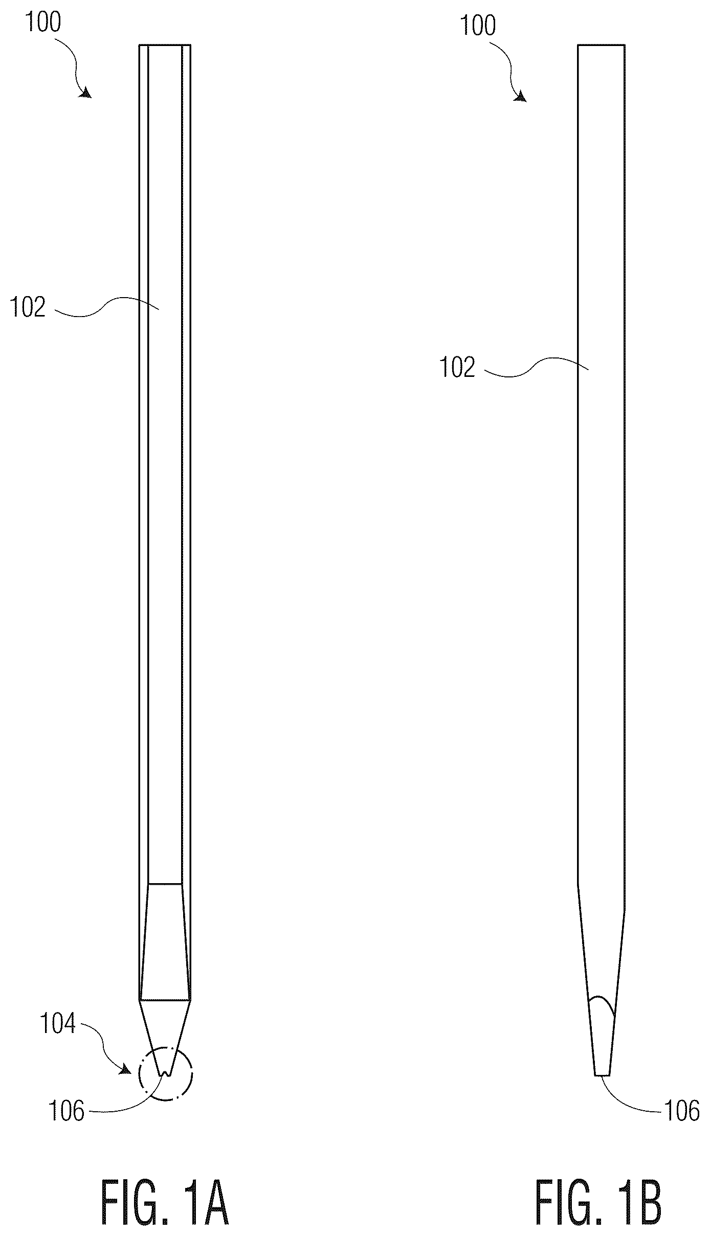
The invention is best understood from the following detailed description when read in connection with the accompanying drawings. It is emphasized that, according to common practice, the various features of the drawings are not to scale. On the contrary, the dimensions of the various features are arbitrarily expanded or reduced for clarity. Included in the drawings are the following figures: A- 1 B are front and side views, respectively, of a wedge bonding tool, in accordance with various exemplary embodiments of the invention; A- 2 C, 3 A- 3 C, 4 A- 4 B, 5 A- 5 B, 6 A- 6 B, 7 A- 7 B, 8 A- 8 B, 9 A- 9 B, 10 A- 10 B, 12 A- 12 C, 13 A - 13 C, 14 A- 14 B, 15 A- 15 C, and 17 A- 17 B are various views of wedge bonding tools, and respective portions of a bonded wire, in accordance with various exemplary embodiments of the invention; , 16 , and 18 are flow diagrams illustrating methods of forming a wire bond on a wire bonding machine, in accordance with various exemplary embodiments of the invention; and A- 19 G are side views illustrating a process of forming two wire loops, including forming stacked wire bonds, in accordance with an exemplary embodiment of the invention.
DETAILED DESCRIPTION
As is known to those skilled in the art, and as used herein, a “wedge bonding tool” is a type of wire bonding tool used in wedge bonding applications and/or on wedge bonding machines. A wedge bonding tool may be contrasted with a “ball bonding tool” (also known as a wire bonding capillary) which is a type of wire bonding tool used in ball bonding applications and/or on ball bonding machines. Exemplary wedge bonding tools according to the invention define a groove in a tip portion, the groove (e.g., a V-shaped groove, a U-shaped groove, etc.) being configured to receive a wire during a wire bonding operation. According to certain exemplary embodiments of the invention, such a groove may also be used to imprint a shape on the wire during a wire bonding operation. Such a shape may be beneficial to additional wire bonding operations occurring at the bonding location, e.g., to form a stacked wire bonding configuration. According to various exemplary embodiments of the invention, wedge bonding tools are provided that improve the stability of stacking wire bonds. Improved stability of stacked wire bonds is desirable, for example, to increase the electrical cross-sectional area and maximum current carried by the wire bond without having to increase a wire size, change wire material, and/or increase bond pad size. According to certain exemplary embodiments of the invention, structural aspects are provided in relation to a groove of a wedge bonding tool (e.g., in relation to a base of the groove) to modify a first wire bond (e.g., to increase a surface area on top of the first wire bond) such that a second wire bond may be reliably stacked on top of the first wire bond, for example, to increase electrical cross-sectional area without increasing bond pad size. According to certain exemplary embodiments of the invention, a bottom of the groove of a wedge bonding tool (e.g., the root or base of the groove) may include a flat area. Such a flat area may have a width of at least 30% of a wire diameter (e.g., of a wire to be wire bonded with the wedge bonding tool). The flat area may be used to create a stable surface on top of a first wire bond (e.g., on top of a first bonded portion), such that a second wire can reliably be bonded to the top of the first wire bond. Such a flat area at the bottom of the groove may have different geometric characteristics as described herein, for example, to further increase the stability of the second stacked wire bond (e.g., protrusions such as teeth, a concave surface, a convex surface, recesses, a specific geometry for a second bond to land on such as a circle pad, amongst others). Wedge bonding tools including the features described herein (e.g., features included in relation to a groove at the tip portion of the wedge bonding tool) may be produced using technologies such as laser micro machining, electrical discharge machining (EDM), etc. A- 1 B illustrate a wedge bonding tool 100 including a body portion 102 having a tip portion 104 . Tip portion 104 defines a groove 106 . A is a front view of wedge bonding tool 100 , and B is a side view of wedge bonding tool 100 . Wedge bonding tool 100 is used to bond a wire to a bonding location on a wire bonding machine. A principal difference between conventional wedge bonding tools and certain wedge bonding tools described herein relates to tip portion 104 , and more specifically, to groove 106 defined by tip portion 104 . Various examples of wedge bonding tool 100 including body portion 102 (including distinct tip portions 104 ) are detailed in A- 2 B (where a wedge bonding tool 100 a includes a tip portion 104 a ), A- 3 B (where a wedge bonding tool 100 b includes a tip portion 104 b ), A (where a wedge bonding tool 100 c includes a tip portion 104 c ), A (where a wedge bonding tool 100 d includes a tip portion 104 d ), A (where a wedge bonding tool 100 e includes a tip portion 104 e ), A (where a wedge bonding tool 100 f includes a tip portion 104 f ), A (where a wedge bonding tool 100 g includes a tip portion 104 g ), A (where a wedge bonding tool 100 h includes a tip portion 104 h ), A (where a wedge bonding tool 100 i includes a tip portion 104 i ), A- 12 B (where a wedge bonding tool 100 j includes a tip portion 104 j ), A- 13 B (where a wedge bonding tool 100 k includes a tip portion 104 k ), A (where a wedge bonding tool 100 l includes a tip portion 104 l ), A- 15 B (where a wedge bonding tool 100 m includes a tip portion 104 m ), and A (where a wedge bonding tool 100 n includes a tip portion 104 n ). Referring now to A- 2 C , A is a perspective view of a tip portion 104 a of a wedge bonding tool 100 a. Tip portion 104 a terminates at a working end 108 a of wedge bonding tool 100 a. Tip portion 104 a also includes two opposing walls 110 a and an adjoining surface 112 a. Adjoining surface 112 a is between, and connects, two opposing walls 110 a. The two opposing walls 110 a are illustrated as meeting adjoining surface 112 a at a respective rounded interface 118 a (e.g., a fillet, blend, round, etc.) but may include a bevel (e.g., a chamfer), an interior corner, or another interface. Adjoining surface 112 a includes a flat area 114 a. Two opposing walls 110 a and flat area 114 a define a groove 106 a. Groove 106 a extends along a groove axis (e.g., the illustrated x-axis). Groove 106 a is configured to receive a wire for a wire bonding operation (e.g., an ultrasonic wire bonding operation). B is a side view of tip portion 104 a. A width W 1 indicates the width of flat area 114 a. A width W 2 indicates the width of groove 106 a at working end 108 a, which, as illustrated, is above flat area 114 a (i.e., along the positive z-axis). According to certain exemplary embodiments of the invention: width W 1 is at least 10% of width W 2 (i.e., the value of W 1 is greater than or equal to 10% of the value of W 2 ); width W 1 is at least 20% of width W 2 ; width W 1 is at least 30% of width W 2 ; width W 1 is at least 40% of width W 2 ; and width W 1 is at least 50% of width W 2 . According to certain exemplary embodiments of the invention: width W 1 is at least 20% of a wire diameter; width W 1 is at least 30% of a wire diameter; and width W 1 is at least 40% of a wire diameter (where the wire diameter is a diameter of the wire being bonding using the wedge bonding tool). These exemplary relationships between width W 1 and width W 2 (and between width W 1 and a wire diameter) are applicable to tip portion 104 a in A- 2 B , but also to tip portion 104 b in A- 3 B , tip portion 104 c in A , tip portion 104 d in A , tip portion 104 e in A , tip portion 104 f in A , tip portion 104 g in A , tip portion 104 h in A , tip portion 104 i in A , and any other tip portion having a flat area as within the scope of the invention. C illustrates a wire 116 a that has been bonded to a bonding location (not shown) using wedge bonding tool 100 a to form a first bonded portion. During a wire bonding operation, wire 116 a was engaged by tip portion 104 a (e.g., fit partially within groove 106 a ). Groove 106 a is configured such that wire 116 a contacted flat area 114 a during the wire bonding operation. Groove 106 a provides an improved grip of tip portion 104 a against wire 116 a during bonding, resulting in improved bonding of wire 116 a to the bonding location. During the wire bonding operation, a portion of wire 116 a was shaped by the geometry of groove 106 a (see shaped wire portion 116 a 1 ). Shaped wire portion 116 a 1 may be considered the “negative” (i.e., the inverse) of the shape of groove 106 a . Shaped wire portion 116 a 1 includes a flat portion 116 a 1 a formed by contact with flat area 114 a of wedge bonding tool 100 a during the wire bonding operation. Shaped wire portion 116 a 1 also includes two angled portions 116 a 1 b resulting from contact with the two opposing walls 110 a. Shaped wire portion 116 a 1 provides a stable bonding surface for a second wire to be bonded on top of the first bonded portion of wire 116 a (e.g., where wire 116 a was the first wire bonded, and the second wire will be bonded on top of the first bonded portion of wire 116 a ). Referring now to A- 3 C , A is a perspective view of a tip portion 104 b of a wedge bonding tool 100 b. Tip portion 104 b terminates at a working end 108 b of wedge bonding tool 100 b. Tip portion 104 b also includes two opposing walls 110 b and an adjoining surface 112 b. Adjoining surface 112 b is between, and connects, two opposing walls 110 b. Two opposing walls 110 b are illustrated as meeting adjoining surface 112 b at a respective rounded interface 118 b (e.g., a fillet, blend, round, etc.) but may include a bevel (e.g., a chamfer), an interior corner, or another interface. Adjoining surface 112 b includes a flat area 114 b. Two opposing walls 110 b and flat area 114 b define a groove 106 b. Groove 106 b extends along a groove axis (e.g., the illustrated x-axis). Groove 106 b is configured to receive a wire for a wire bonding operation (e.g., an ultrasonic wire bonding operation). A plurality of protrusions 114 b 1 extend from flat area 114 b . Protrusions 114 b 1 each include a quadrilateral shape (e.g., square, rectangle, parallelogram, etc.), but the invention is not limited thereto, as the protrusions may include any other shape (e.g., circular, triangular, etc.). Further, the invention is not limited to a plurality of protrusions 114 b 1 , as a single protrusion is contemplated. B illustrates a side view of tip portion 104 b. A width W 1 indicates the width of flat area 114 b. A width W 2 indicates the width of groove 106 b at working end 108 b, which, as illustrated, is directly above flat area 114 b (i.e., along the positive z-axis). Width W 1 and width W 2 of B have the same relationship as described in connection with width W 1 and width W 2 of B . C illustrates a wire 116 b that has been bonded to a bonding location (not shown) using wedge bonding tool 100 b to form a first bonded portion. During a wire bonding operation, wire 116 b was engaged by tip portion 104 b (e.g., fit partially within groove 106 b ). Groove 106 b is configured such that wire 116 b contacted flat area 114 b (and protrusions 114 b 1 ) during the wire bonding operation. Groove 106 b provides an improved grip of tip portion 104 b against wire 116 b during bonding, resulting in improved bonding of wire 116 b to the bonding location. During the wire bonding operation, a portion of wire 116 b was shaped by the geometry of groove 106 b (see shaped wire portion 116 b 1 ). Shaped wire portion 116 b 1 may be considered the “negative” (i.e., the inverse) of the shape of groove 106 b. Shaped wire portion 116 b 1 includes a flat portion 116 b 1 a with a plurality of recesses 116 b 1 a ′ formed by contact with flat area 114 b (including protrusions 114 b 1 ) during the wire bonding operation. Shaped wire portion 116 b 1 also includes two angled portions 116 b 1 b resulting from contact with the two opposing walls 110 b. Shaped wire portion 116 b 1 provides a stable bonding surface for a second wire to be bonded on top of the first bonded portion of wire 116 b (e.g., where wire 116 b was the first wire bonded, and the second wire will be bonded on top of the first bonded portion of wire 116 b ). Referring now to A- 4 B , A is a perspective view of a tip portion 104 c of a wedge bonding tool 100 c. Tip portion 104 c terminates at a working end 108 c of wedge bonding tool 100 c. Tip portion 104 c also includes two opposing walls 110 c and an adjoining surface 112 c. Adjoining surface 112 c is between, and connects, two opposing walls 110 c. Two opposing walls 110 c are illustrated as meeting adjoining surface 112 c at a respective rounded interface 118 c (e.g., a fillet, blend, round, etc.) but may include a bevel (e.g., a chamfer), an interior corner, or another interface. Adjoining surface 112 c includes a flat area 114 c. Two opposing walls 110 c and flat area 114 c define a groove 106 c. Groove 106 c extends along a groove axis (e.g., the illustrated x-axis). Groove 106 c is configured to receive a wire for a wire bonding operation (e.g., an ultrasonic bonding operation). A plurality of protrusions extends from flat area 114 c in the form of ridges 114 c 1 extending between, and connecting, the two opposing walls 110 c. Ridges 114 c 1 are illustrated as having a triangular shape (e.g., a sawtooth shape), but the invention is not limited thereto, as the ridges may include any other shape (e.g., a rounded shape, a rectangular shape, a spiked shape, etc.). Further, the invention is not limited to a plurality of protrusions (e.g., ridges), as a single protrusion (e.g., a single ridge) is contemplated. B illustrates a wire 116 c that has been bonded to a bonding location (not shown) using wedge bonding tool 100 c to form a first bonded portion. During a wire bonding operation, wire 116 c was engaged by tip portion 104 c (e.g., fit partially within groove 106 c ). Groove 106 c is configured such that wire 116 c contacted flat area 114 c (and ridges 114 c 1 ) during the wire bonding operation. Groove 106 c provides an improved grip of tip portion 104 c against wire 116 c during bonding, resulting in improved bonding of wire 116 c to the bonding location. During the wire bonding operation, a portion of wire 116 c was shaped by the geometry of groove 106 c (see shaped wire portion 116 c 1 ). Shaped wire portion 116 c 1 may be considered the “negative” (i.e., the inverse) of the shape of groove 106 c. Shaped wire portion 116 c 1 includes a flat portion 116 c 1 a with a plurality of recesses 116 c 1 a ′ formed by contact with flat area 114 c (and ridges 114 c 1 ) of wedge bonding tool 100 c during the wire bonding operation. Shaped wire portion 116 c 1 also includes two angled portions 116 c 1 b resulting from contact with the two opposing walls 110 c. Shaped wire portion 116 c 1 provides a stable bonding surface for a second wire to be bonded on top of the first bonded portion of wire 116 c (e.g., where wire 116 c was the first wire bonded, and the second wire will be bonded on top of the first bonded portion of wire 116 c ). Referring now to A- 5 B , A is a perspective view of a tip portion 104 d of a wedge bonding tool 100 d. Tip portion 104 d terminates at a working end 108 d of wedge bonding tool 100 d. Tip portion 104 d also includes two opposing walls 110 d and an adjoining surface 112 d. Adjoining surface 112 d is between, and connects, two opposing walls 110 d. Two opposing walls 110 d are illustrated as meeting adjoining surface 112 d at a respective rounded interface 118 d (e.g., a fillet, blend, round, etc.) but may include a bevel (e.g., a chamfer), an interior corner, or another interface. Adjoining surface 112 d includes a flat area 114 d. Two opposing walls 110 d and flat area 114 d define a groove 106 d. Groove 106 d extends along a groove axis (e.g., the illustrated x-axis). Groove 106 d is configured to receive a wire for a wire bonding operation (e.g., an ultrasonic bonding operation). Adjoining surface 112 d includes a concave portion 112 d 1 on the feed side of wedge bonding tool 100 d (i.e., the side from which the wire feeds into tip portion 104 d ) that is adjacent to flat area 114 d. B illustrates a wire 116 d that has been bonded to a bonding location (not shown) using wedge bonding tool 100 d to form a first bonded portion. During a wire bonding operation, wire 116 d was engaged by tip portion 104 d (e.g., fit partially within groove 106 d ). Groove 106 d is configured such that wire 116 d contacted flat area 114 d (and concave portion 112 d 1 ) during the wire bonding operation. Groove 106 d provides an improved grip of tip portion 104 d against wire 116 d during bonding, resulting in improved bonding of wire 116 d to the bonding location. During the wire bonding operation, a portion of wire 116 d was shaped by the geometry of groove 106 d (see shaped wire portion 116 d 1 ). Shaped wire portion 116 d 1 may be considered the “negative” (i.e., the inverse) of the shape of groove 106 d. Shaped wire portion 116 d 1 includes a flat portion 116 d 1 a formed by contact with flat area 114 d of wedge bonding tool 100 d during the wire bonding operation. Shaped wire portion 116 d 1 also includes two angled portions 116 d 1 b resulting from contact with the two opposing walls 110 d. Additionally, shaped wire portion 116 d 1 includes a convex portion 116 d 1 c on the “heel” of wire 116 d (i.e., where wire 116 d transitions away from shaped wire portion 116 d 1 ) that is formed by contact with concave portion 112 d 1 . Shaped wire portion 116 d 1 provides a stable bonding surface for a second wire to be bonded on top of the first bonded portion of wire 116 d (e.g., where wire 116 d was the first wire bonded, and the second wire will be bonded on top of the first bonded portion of wire 116 d ). Referring now to A- 6 B , A is a perspective view of a tip portion 104 e of a wedge bonding tool 100 e. Tip portion 104 e terminates at a working end 108 e of wedge bonding tool 100 e. Tip portion 104 e also includes two opposing walls 110 e and an adjoining surface 112 e. Adjoining surface 112 e is between, and connects, two opposing walls 110 e. Two opposing walls 110 e are illustrated as meeting adjoining surface 112 e at a respective interior corner 118 e, but may include a rounded interface (e.g., a fillet, blend, round, etc.), a bevel (e.g., a chamfer), or another interface. Adjoining surface 112 e includes a recess 112 e 1 and a flat area 114 e, wherein recess 112 e 1 surrounds flat area 114 e. In the example illustrated in A , flat area 114 e is rectangular. However, the invention is not so limited, as other flat area shapes are contemplated (e.g., circular, square, triangular, star-shaped, etc.). Recess 112 e 1 is illustrated as exceeding the width of adjoining surface 112 e. That is, two opposing walls 110 e define part of recess 112 e 1 , where two opposing walls 110 e trace an edge of adjoining surface 112 e and extend at a slight angle from the z-axis from adjoining surface 112 e. However, it is within the scope of the invention to include a recess that does not exceed the width of adjoining surface 112 e. Two opposing walls 110 e and flat area 114 e define a groove 106 e. Groove 106 e extends along a groove axis (e.g., the illustrated x-axis). Groove 106 e is configured to receive a wire for a wire bonding operation (e.g., an ultrasonic bonding operation). B illustrates a wire 116 e that has been bonded to a bonding location (not shown) using wedge bonding tool 100 e to form a first bonded portion. During a wire bonding operation, wire 116 e was engaged by tip portion 104 e (e.g., fit partially within groove 106 e ). Groove 106 e is configured such that wire 116 e contacted flat area 114 e (and the surfaces defining recess 112 e 1 ) during the wire bonding operation. Groove 106 e provides an improved grip of tip portion 104 e against wire 116 e during bonding, resulting in improved bonding of wire 116 e to the bonding location. During the wire bonding operation, a portion of wire 116 e was shaped by the geometry of groove 106 e (see shaped wire portion 116 e 1 ). Shaped wire portion 116 e 1 may be considered the “negative” (i.e., the inverse) of the shape of groove 106 e. Shaped wire portion 116 e 1 includes a flat portion 116 e 1 a formed by contact with flat area 114 e of wedge bonding tool 100 e during the wire bonding operation. Shaped wire portion 116 e 1 also includes two angled portions 116 e 1 b resulting from contact with the two opposing walls 110 e. Additionally, shaped wire portion 116 e 1 includes a raised portion 116 e 1 c surrounding flat portion 1161 a that is formed by contact with the surfaces defining recess 112 e 1 . Shaped wire portion 116 e 1 provides a stable bonding surface for a second wire to be bonded on top of the first bonded portion of wire 116 e (e.g., where wire 116 e was the first wire bonded, and the second wire will be bonded on top of the first bonded portion of wire 116 e ). Referring now to A- 7 B , A is a perspective view of a tip portion 104 f of a wedge bonding tool 100 f. Tip portion 104 f terminates at a working end 108 f of wedge bonding tool 100 f. Tip portion 104 f also includes two opposing walls 110 f and an adjoining surface 112 f. Adjoining surface 112 f is between, and connects, two opposing walls 110 f. Adjoining surface 112 f defines two recesses 1121 a and 112 f 1 b and includes a flat area 114 f. Recesses 112 f 1 a and 112 f 1 b each extend between one of the two opposing walls and the flat area (e.g., each of recesses 1121 a and 112 f 1 b lie at an interface between one of the two opposing walls 110 f and flat area 114 f ). Recesses 112 f 1 a / 112 f 1 b are shown as having a cylindrical shape; however other shapes are contemplated (e.g., triangular, rectangular, etc.). Recesses 112 f 1 a/b are illustrated as exceeding the width of adjoining surface 112 f. That is, the opposing walls 110 f define parts of recesses 112 f 1 a / 112 f 1 b, where two opposing walls 110 f each trace an edge of adjoining surface 112 f and extend at a slight angle from the z-axis from adjoining surface 112 f. However, it is within the scope of the invention to include recesses that do not exceed the width of adjoining surface 112 f. Two opposing walls 110 f and flat area 114 f define a groove 106 f . Groove 106 f extends along a groove axis (e.g., the illustrated x-axis). Groove 106 f is configured to receive a wire for a wire bonding operation (e.g., an ultrasonic bonding operation). B illustrates a wire 116 f that has been bonded to a bonding location (not shown) using wedge bonding tool 100 f to form a first bonded portion. During a wire bonding operation, wire 116 f was engaged by tip portion 104 f (e.g., fit partially within groove 106 f ). Groove 106 f is configured such that wire 116 f contacted flat area 114 f and the surfaces defining recesses 112 f 1 a / 112 f 1 b during the wire bonding operation. Groove 106 f provides an improved grip of tip portion 104 f against wire 116 f during bonding, resulting in improved bonding of the wire to the bonding location. During the wire bonding operation, a portion of wire 116 f was shaped by the geometry of groove 106 f (see shaped wire portion 116 f 1 ). Shaped wire portion 116 f 1 may be considered the “negative” (i.e., the inverse) of the shape of groove 106 f. Shaped wire portion 116 f 1 includes a flat portion 116 f 1 a formed by contact with flat area 114 f of wedge bonding tool 100 f during the wire bonding operation. Shaped wire portion 116 f 1 also includes two angled portions 116 f 1 b resulting from contact with the two opposing walls 110 f. Additionally, shaped wire portion 116 f 1 includes two raised portions 116 f 1 c and 116 f 1 c ′ formed by contact with the surfaces defining recesses 112 f 1 a and 112 f 1 b. Shaped wire portion 116 f 1 provides a stable bonding surface for a second wire to be bonded on top of the first bonded portion of wire 116 f (e.g., where wire 116 f was the first wire bonded, and the second wire will be bonded on top of the first bonded portion of wire 116 f ). Referring now to A- 8 B , A is a perspective view of a tip portion 104 g of a wedge bonding tool 100 g. Tip portion 104 g terminates at a working end 108 g wedge bonding tool 100 g. Tip portion 104 g also includes two opposing walls 110 g and an adjoining surface 112 g. Adjoining surface 112 g is between, and connects, two opposing walls 110 g. Adjoining surface 112 g includes two recesses 112 g 1 a and 112 g 1 b and a flat area 114 g, wherein recesses 112 g 1 a / 112 g 1 b each extend between two opposing walls 110 g on opposite sides of flat area 114 g at an interface between flat area 114 g and the non-flat portion of adjoining surface 112 g. Recesses 112 g 1 a / 112 g 1 b are shown as having a trapezoidal cross-section; however other shapes are contemplated (e.g., a cylindrical, rectangular, etc.). Recesses 112 g 1 a / 112 g 1 b are illustrated as exceeding the width of adjoining surface 112 g. That is, two opposing walls 110 g define parts of recesses 112 g 1 a / 112 g 1 b, where two opposing walls 110 g trace an edge of the adjoining surface and extend at a slight angle from the z-axis from adjoining surface 112 g. However, it is within the scope of the invention to include recesses that do not exceed the width of adjoining surface 112 g. Two opposing walls 110 g and flat area 114 g define a groove 106 g. Groove 106 g extends along a groove axis (e.g., the illustrated x-axis). Groove 106 g is configured to receive a wire for a wire bonding operation (e.g., an ultrasonic bonding operation). B illustrates a wire 116 g that has been bonded to a bonding location (not shown) using wedge bonding tool 100 g to form a first bonded portion. During a wire bonding operation, wire 116 g was engaged by tip portion 104 g (e.g., fit partially within groove 106 g ). Groove 106 g is configured such that wire 116 g contacted flat area 114 g (and the surfaces defining recesses 112 g 1 a / 112 g 1 b ) during the wire bonding operation. Groove 106 g provides an improved grip of tip portion 104 g against wire 116 g during bonding, resulting in improved bonding of wire 116 g to the bonding location. During the wire bonding operation, a portion of wire 116 g was shaped by the geometry of groove 106 g (see shaped wire portion 116 g 1 ). Shaped wire portion 116 g 1 may be considered the “negative” (i.e., the inverse) of the shape of groove 106 g. Shaped wire portion 116 g 1 includes a flat portion 116 g 1 a formed by contact with flat area 114 g of wedge bonding tool 100 g during the wire bonding operation. Shaped wire portion 116 g 1 also includes two angled portions 116 g 1 b resulting from contact with the two opposing walls 110 g . Additionally, shaped wire portion 116 g 1 includes two raised portions 116 g 1 c and 116 g 1 c ′ formed by contact with the surfaces defining recesses 112 g 1 a and 112 g 1 b. Shaped wire portion 116 g 1 provides a stable bonding surface for a second wire to be bonded on top of the first bonded portion of wire 116 g (e.g., where wire 116 g was the first wire bonded, and the second wire will be bonded on top of the first bonded portion of wire 116 g ). Referring now to A- 9 B , A is a perspective view of a tip portion 104 h of a wedge bonding tool 100 h. Tip portion 104 h terminates at a working end 108 h of wedge bonding tool 100 h. Tip portion 104 h also includes two opposing walls 110 h and an adjoining surface 112 h. Adjoining surface 112 h is between, and connects, two opposing walls 110 h. Adjoining surface 112 h includes a recess 112 h 1 and a flat area 114 h, wherein recess 112 h 1 divides flat area 114 h. As illustrated, recess 112 h 1 bisects flat area 114 h along the y-axis. However, the invention is not limited thereto, as a recess could be at another location (e.g., a recess dividing a flat area into unequal parts) and/or divide a flat area at a different angle (e.g., along the x-axis, at a diagonal, etc.). Recess 112 h 1 is illustrated as having a cylindrical cross-section; however other shapes are contemplated (e.g., triangular, rectangular, etc.). Recess 112 h 1 is illustrated as exceeding the width of adjoining surface 112 h. That is, two opposing walls 110 h define parts of recess 112 h 1 , where the two opposing walls 110 h trace an edge of the adjoining surface and extend at a slight angle from the z-axis from adjoining surface 112 h. However, it is within the scope of the invention to include a recess that does not exceed the width of adjoining surface 112 h. Two opposing walls 110 h and flat area 114 h define a groove 106 h. Groove 106 h extends along a groove axis (e.g., the illustrated x-axis). Groove 106 h is configured to receive a wire for a wire bonding operation (e.g., an ultrasonic bonding operation). B illustrates a wire 116 h that has been bonded to a bonding location (not shown) using wedge bonding tool 100 h to form a first bonded portion. During a wire bonding operation, wire 116 h was engaged by tip portion 104 h (e.g., fit partially within groove 106 h ). Groove 106 h is configured such that wire 116 h contacted flat area 114 h (and the surfaces defining recess 112 h 1 ) during the wire bonding operation. Groove 106 h provides an improved grip of tip portion 104 h against wire 116 h during bonding, resulting in improved bonding of wire 116 h to the bonding location. During the wire bonding operation, a portion of wire 116 h was shaped by the geometry of groove 106 h (see shaped wire portion 116 h 1 ). Shaped wire portion 116 h 1 may be considered the “negative” (i.e., the inverse) of the shape of groove 106 h. Shaped wire portion 116 h 1 includes a flat portion 116 h 1 a formed by contact with flat area 114 h of wedge bonding tool 100 h during the wire bonding operation. Shaped wire portion 116 h 1 also includes two angled portions 116 h 1 b resulting from contact with two opposing walls 110 h. Additionally, shaped wire portion 116 h 1 includes a raised portion 116 h 1 c formed by contact with the surfaces defining recess 112 h 1 . Shaped wire portion 116 h 1 provides a stable bonding surface for a second wire to be bonded on top of the first bonded portion of wire 116 h (e.g., where wire 116 h was the first wire bonded, and the second wire will be bonded on top of the first bonded portion of wire 116 h ). Referring now to A- 10 B , A is a perspective view of a tip portion 104 i of a wedge bonding tool 100 i. Tip portion 104 i terminates at a working end 108 i of wedge bonding tool 100 i. Tip portion 104 i also includes two opposing walls 110 i and an adjoining surface 112 i. Adjoining surface 112 i is between, and connects, two opposing walls 110 i. Adjoining surface 112 i includes a recess 112 i 1 and a flat area 114 i . Flat area 114 i is contained in recess 112 i 1 . Recess 112 i 1 has a circular shape, although the invention is not limited thereto, as the recess could have any other shape (e.g., rectangular, star-shaped, triangular, etc.). If the recess were not circular, it is contemplated that the recess could have any orientation (e.g., a rectangular recess with the long dimension parallel to the x-axis or the y-axis). As illustrated, recess 112 i 1 is centered between the two opposing walls 110 i in both the x-direction and the y-direction; however, it is contemplated that the recess could be in a different location (e.g., closer to one opposing wall than the other, closer to the wire feed side of the wedge bonding tool, etc.). Recess 112 i 1 is illustrated as exceeding the width of adjoining surface 112 i. That is, the two opposing walls 110 i define parts of recess 112 i 1 , where the two opposing walls 110 i trace an edge of the adjoining surface and extend at a slight angle from the z-axis from adjoining surface 112 i. However, it is within the scope of the invention to include recesses that do not exceed the width of adjoining surface 112 i (e.g., a circular recess that has a smaller diameter). Two opposing walls 110 i and flat area 114 i define a groove 106 i . Groove 106 i extends along a groove axis (e.g., the illustrated x-axis). Groove 106 i is configured to receive a wire for a wire bonding operation (e.g., an ultrasonic bonding operation). Wedge bonding tool 100 i may be used to bond a wire to a bonding location on a wire bonding machine. B illustrates a wire 116 i that has been bonded to a bonding location (not shown) using wedge bonding tool 100 i to form a first bonded portion. During a wire bonding operation, wire 116 i was engaged by tip portion 104 i (e.g., fit partially within groove 106 i ). Groove 106 i is configured such that wire 116 i contacted flat area 114 i (and the surfaces defining recess 112 i 1 ) during the wire bonding operation. Groove 106 i provides an improved grip of tip portion 104 i against wire 116 i during bonding, resulting in improved bonding of the wire to a bonding location. During the wire bonding operation, a portion of wire 116 i was shaped by the geometry of groove 106 i (see shaped wire portion 116 i 1 ). Shaped wire portion 116 i 1 may be considered the “negative” (i.e., the inverse) of the shape of groove 106 i. Shaped wire portion 116 i 1 includes a flat portion 116 i 1 a formed by contact with flat area 114 i of wedge bonding tool 100 i during the wire bonding operation. Shaped wire portion 116 i 1 also includes two angled portions 116 i 1 b resulting from contact with two opposing walls 110 i. Additionally, shaped wire portion 116 i 1 includes a raised portion 116 i 1 c formed by contact with the surfaces defining recess 1121 a . Since flat area 114 i is contained in recess 112 i 1 , flat portion 116 i 1 a is on raised portion 116 i 1 c on wire 116 i. Shaped wire portion 116 i 1 provides a stable bonding surface for a second wire to be bonded on top of the first bonded portion of wire 116 i (e.g., where wire 116 i was the first wire bonded, and the second wire will be bonded on top of the first bonded portion of wire 116 i ). is a flow diagram illustrating a method of forming a wire bond on a wire bonding machine. At Step 1100 , a wedge bonding tool (e.g., any of wedge bonding tools 100 a, 100 b, 100 c, 100 d, 100 e, 100 f, 100 g, 100 h, and 100 i ) is provided. The wedge bonding tool includes a body portion having a tip portion. The tip portion terminates at a working end of the wedge bonding tool. The tip portion includes (i) two opposing walls, and (ii) an adjoining surface between the two opposing walls. The adjoining surface includes a flat area, the two opposing walls and the flat area defining a groove configured to receive a wire. The flat area has a width of at least 20% of a width of the groove at the working end. At Step 1102 , a first wire is bonded to a wire bonding location using the wedge bonding tool. At Step 1104 , a second wire is bonded to the first bonded portion (e.g., at a bonded portion of the first wire) using the wedge bonding tool. As is understood by those skilled in the art, certain steps included in the flow diagram may be omitted; certain additional steps may be added; and the order of the steps may be altered from the order illustrated—all within the scope of the invention. The embodiments illustrated and described in include a groove 106 including a flat area (e.g., flat area 114 a - i ). However, achieving stability for stacking wire bonds may also be achieved with a convex portion rather than a flat area. are described herein with reference to exemplary convex portions (e.g., convex portions 114 j - m ). Referring now to A- 12 C , A is a perspective view of a tip portion 104 j of a wedge bonding tool 100 j. Tip portion 104 j terminates at a working end 108 j of wedge bonding tool 100 j. Tip portion 104 j also includes two opposing walls 110 j and an adjoining surface 112 j. Adjoining surface 112 j is between, and connects, two opposing walls 110 j. Two opposing walls 110 j are illustrated as meeting adjoining surface 112 j at a respective interior corner 118 j, but may include a rounded interface (e.g., a fillet, blend, round, etc.), a bevel (e.g., a chamfer), or another interface. Adjoining surface 112 j includes a convex portion 114 j. Two opposing walls 110 j and convex portion 114 j define a groove 106 j. Groove 106 j extends along a groove axis (e.g., the illustrated x-axis). Groove 106 j is configured to receive a wire for a wire bonding operation (e.g., an ultrasonic bonding operation). B is a side view of tip portion 104 j. A width W 1 indicates the width of convex portion 114 j. A width W 2 indicates the width of groove 106 j at working end 108 j, which, as illustrated, is above convex portion 114 j (i.e., along the positive z-axis). According to certain exemplary embodiments of the invention: width W 1 is at least 10% of width W 2 ; width W 1 is at least 20% of width W 2 ; width W 1 is at least 30% of width W 2 ; width W 1 is at least 40% of width W 2 ; and width W 1 is at least 50% of width W 2 . According to certain exemplary embodiments of the invention: width W 1 is at least 20% of a wire diameter; width W 1 is at least 30% of a wire diameter; and width W 1 is at least 40% of a wire diameter (where the wire diameter is a diameter of the wire being bonding using the wedge bonding tool). These exemplary relationships between width W 1 and width W 2 (and between width W 1 and a wire diameter) are applicable to tip portion 104 j in A- 12 B , tip portion 104 k in A- 13 B , tip portion 1041 in A , tip portion 104 m in A- 15 B , and any other tip portion having a convex portion as within the scope of the invention. C illustrates a wire 116 j that has been bonded to a bonding location (not shown) using wedge bonding tool 100 j to form a first bonded portion. During a wire bonding operation, wire 116 j was engaged by tip portion 104 j (e.g., fit partially within groove 106 j ). Groove 106 j is configured such that wire 116 j contacted convex portion 114 j during the wire bonding operation. Groove 106 j provides an improved grip of tip portion 104 j against wire 116 j during bonding resulting in improved bonding of wire 116 j to the bonding location. During the wire bonding operation, a portion of wire 116 j was shaped by the geometry of groove 106 j (see shaped wire portion 116 j 1 ). Shaped wire portion 116 j 1 may be considered the “negative” (i.e., the inverse) of the shape of groove 106 j. Shaped wire portion 116 j 1 includes a concave portion 116 j 1 a formed by contact with convex portion 114 j of wedge bonding tool 100 j during the wire bonding operation. Shaped wire portion 116 j 1 also includes two angled portions 116 j 1 b resulting from contact with two opposing walls 110 j. Shaped wire portion 116 j 1 provides a stable bonding surface for a second wire to be bonded on top of the first bonded portion of wire 116 j (e.g., where wire 116 j was the first wire bonded, and the second wire will be bonded on top of the first bonded portion of wire 116 j ). Referring now to A- 13 C , A is a perspective view of a tip portion 104 k of a wedge bonding tool 100 k. Tip portion 104 k terminates at a working end 108 k of wedge bonding tool 100 k. Tip portion 104 k also includes two opposing walls 110 k and an adjoining surface 112 k. Adjoining surface 112 k is between and connects two opposing walls 110 k. Two opposing walls 110 k are illustrated as meeting adjoining surface 112 k at a respective rounded interface 118 k (e.g., a fillet, blend, round, etc.), but may include a bevel (e.g., a chamfer), an interior corner, or another interface. Adjoining surface 112 k includes a convex portion 114 k. Convex portion 114 k is convex/curved about the x-axis and includes a hemispherical end, thus resembling a portion of a cylinder with hemispherical ends (i.e., a capsule shape). However, it is contemplated that the end portion could be any other shape (e.g., conical, square, etc.). Convex portion 114 k may also be described as being curved across a width of a groove 106 k (see B ). Two opposing walls 110 k and convex portion 114 k define groove 106 k. Groove 106 k extends along a groove axis (e.g., the illustrated x-axis). Groove 106 k is configured to receive a wire for a wire bonding operation (e.g., an ultrasonic bonding operation). B illustrates a side view of tip portion 104 k. A width W 1 indicates the width of convex portion 114 k. A width W 2 indicates the width of groove 106 k at working end 108 k, which, as illustrated, is directly above convex portion 114 k (i.e., along the positive z-axis). C illustrates a wire 116 k that has been bonded to a bonding location (not shown) using wedge bonding tool 100 k to form a first bonded portion. During a wire bonding operation, wire 116 k was engaged by tip portion 104 k (e.g., fit partially within groove 106 k ). Groove 106 k provides improved grip of tip portion 104 k against wire 116 k during bonding, resulting in improved bonding of wire 116 k to the bonding location. During the wire bonding operation, a portion of wire 116 k was shaped by the geometry of groove 106 k (see shaped wire portion 116 k 1 ). Shaped wire portion 116 k 1 may be considered the “negative” (i.e., the inverse) of the shape of groove 106 k. Shaped wire portion 116 k 1 includes a concave portion 116 k 1 a formed by contact with convex portion 114 k of wedge bonding tool 100 k during the wire bonding operation. Shaped wire portion 116 k 1 also includes two angled portions 116 k 1 b resulting from contact with two opposing walls 110 k. Shaped wire portion 116 k 1 provides a stable bonding surface for a second wire to be bonded on top of the first bonded portion of wire 116 k (e.g., where wire 116 k was the first wire bonded, and the second wire will be bonded on top of the first bonded portion of wire 116 k ). Referring now to A- 14 B , A is a perspective view of a tip portion 104 l of a wedge bonding tool 100 l . Tip portion 104 l terminates at a working end 108 l of wedge bonding tool 100 l . Tip portion 104 l also includes an adjoining surface 112 l and two opposing walls 110 l . Adjoining surface 112 l is between, and connects, two opposing walls 110 l . Two opposing walls 110 l are illustrated as meeting adjoining surface 112 l at a respective rounded interface 118 l (e.g., a fillet, blend, round, etc.), but may include a bevel (e.g., a chamfer), an interior corner, or another interface. Adjoining surface 112 l includes a convex portion 114 l . Convex portion 114 l is convex/curved about both the x-axis and the y-axis, resembling a portion of an ovoid shape (e.g., an egg shape). Two opposing walls 110 l each include an indent 110 l 1 adjacent to convex portion 114 l . Indent 110 l 1 has a round shape that is truncated at working end 108 l . However, the invention is not so limited, as it is contemplated that the indent could have a different shape (e.g., trapezoidal, square, star shaped, etc.), size (e.g., smaller or larger than shown), or location (e.g., a different location on each of the two opposing walls). Convex portion 114 i may also be described as being curved across a width of a groove 106 l . The two opposing walls 110 1 and convex portion 114 i define groove 106 l . Groove 106 l extends along a groove axis (e.g., the illustrated x-axis). Groove 106 l is configured to receive a wire for a wire bonding operation (e.g., an ultrasonic bonding operation). Like the embodiments described above, convex portion 114 l may have a width W 1 (not labelled in A , but see B and 13 B for an illustration of width W 1 versus width W 2 of groove 106 l at working end 108 l ). B illustrates a wire 116 l that has been bonded to a bonding location (not shown) using wedge bonding tool 100 l to form a first bonded portion. During a wire bonding operation, wire 116 l was engaged by tip portion 104 l (e.g., fit partially within groove 106 l ). Groove 106 l is configured such that wire 116 l contacted convex portion 114 l during the wire bonding operation. Groove 106 l provides an improved grip of tip portion 104 l against wire 116 l during bonding resulting in improved bonding of wire 116 l to the bonding location. During the wire bonding operation, a portion of wire 116 1 was shaped by the geometry of groove 106 l (see shaped wire portion 116 l 1 ). Shaped wire portion 116 l 1 may be considered the “negative” (i.e., the inverse) of the shape of groove 106 l . Shaped wire portion 116 l 1 includes a concave portion 116 l 1 a formed by contact with convex portion 114 l of wedge bonding tool 100 l during the wire bonding operation. Shaped wire portion 116 l 1 also includes two angled portions 116 l 1 b resulting from contact with two opposing walls 110 l . Each angled portion 116 l 1 b includes a protrusion 116 l 1 c formed by contact with the indents 110 l 1 of the two opposing walls 110 l . Shaped wire portion 116 l 1 provides a stable bonding surface for a second wire to be bonded on top of the first bonded portion of wire 116 l (e.g., where wire 116 l was the first wire bonded, and the second wire will be bonded on top of the first bonded portion of wire 116 l ). Referring now to A- 15 C , A is a perspective view of a tip portion 104 m of a wedge bonding tool 100 m. Tip portion 104 m terminates at a working end 108 m of wedge bonding tool 100 m. Tip portion 104 m also includes an adjoining surface 112 m and two opposing walls 110 m. Adjoining surface 112 m is between, and connects, two opposing walls 110 m. Two opposing walls 110 m are illustrated as meeting adjoining surface 112 m at a respective rounded interface 118 m (e.g., a fillet, blend, round, etc.), but may include a bevel (e.g., a chamfer), an interior corner, or another interface. Adjoining surface 112 m includes a convex portion 114 m. Convex portion 114 m is convex/curved about both the x-axis and the y-axis, resembling an ellipsoid (e.g., a flattened sphere, a disk shape, a flying saucer shape). Two opposing walls 110 m and convex portion 114 m define a groove 106 m. Groove 106 m extends along a groove axis (e.g., the illustrated x-axis). Groove 106 m is configured to receive a wire for a wire bonding operation (e.g., an ultrasonic bonding operation). B illustrates a side view of tip portion 104 m. A width W 1 indicates the width of convex portion 114 m. A width W 2 indicates the width of groove 106 m at working end 108 m, which, as illustrated, is above convex portion 114 m (i.e., along the positive z-axis). C illustrates a wire 116 m that has been bonded to a bonding location (not shown) using wedge bonding tool 100 m to form a first bonded portion. During a wire bonding operation, wire 116 m was engaged by tip portion 104 m (e.g., fit partially within groove 106 m ). Groove 106 m is configured such that wire 116 m contacted convex portion 114 m during the wire bonding operation. Groove 106 m provides an improved grip of tip portion 104 m against wire 116 m during bonding resulting in improved bonding of wire 116 m to the bonding location. During the wire bonding operation, a portion of wire 116 m was shaped by the geometry of groove 106 m (see shaped wire portion 116 m 1 ). Shaped wire portion 116 m 1 may be considered the “negative” (i.e., the inverse) of the shape of groove 106 m. Shaped wire portion 116 m 1 includes a concave portion 116 m 1 a formed by contact with convex portion 114 m of wedge bonding tool 100 m during the wire bonding operation. Shaped wire portion 116 m 1 also includes two angled portions 116 m 1 b resulting from contact with two opposing walls 110 m. Shaped wire portion 116 m 1 provides a stable bonding surface for a second wire to be bonded on top of the first bonded portion of wire 116 m (e.g., where wire 116 m was the first wire bonded, and the second wire will be bonded on top of the first bonded portion of wire 116 m ). is a flow diagram illustrating a method of forming a wire bond on a wire bonding machine. At Step 1600 , a wedge bonding tool (e.g., any of wedge bonding tools 100 j, 100 k, 100 l , and 100 m ) is provided. The wedge bonding tool includes a body portion having a tip portion. The tip portion terminates at a working end of the wedge bonding tool. The tip portion includes (i) two opposing walls, and (ii) an adjoining surface between the two opposing walls. The adjoining surface includes a convex portion, the two opposing walls and the convex portion defining a groove configured to receive a wire. The convex portion may have a width (e.g., width W 1 in B, 13 B, and 15 B ) of at least 20% of a width of the groove at the working end (e.g., width W 2 in B, 13 B, and 15 B ). At Step 1602 , a first wire is bonded to a wire bonding location using the wedge bonding tool to form a first bonded portion. At Step 1604 , a second wire is bonded to the first bonded portion (e.g., at a bonded portion of the first wire) using the wedge bonding tool. As is understood by those skilled in the art, certain steps included in the flow diagram may be omitted; certain additional steps may be added; and the order of the steps may be altered from the order illustrated—all within the scope of the invention. In the above-described embodiments, wedge bonding tools 100 a - 100 m (or any other wedge bonding tool within the scope of the invention) includes a groove for shaping a surface of a first wire during a wire bonding process to create a stable bonding surface for a second wire. However, other processes are contemplated for creating the stable bonding surface of a second wire. A illustrates an exemplary tool used to create a stable bonding surface on the first wire by pressing a portion of the first wire to shape a portion of the wire. Referring specifically to A , a wedge bonding tool 100 n with a tip portion 104 n is provided. The tip portion terminates at a working end 108 n. Tip portion 104 n includes two opposing walls 110 n and an adjoining surface 112 n. A groove 106 n is defined by two opposing walls 110 n and adjoining surface 112 n. Groove 106 n is configured to receive a wire during a wire bonding operation. Groove 106 n has a width W 1 , representing the narrowest distance between two opposing walls 110 n at working end 108 n. Working end 108 n has end portions 108 n 1 and 108 n 2 on either side of groove 106 n. At least one of end portions 108 n 1 and 108 n 2 has a width W 2 that that is at least 80% of width W 1 (as illustrated, end portion 108 n 2 has W 2 that is at least 80% of width W 1 ). Other relationships between width W 2 and width W 1 are contemplated (e.g., width W 2 being at least 100% of width W 1 , etc.). B illustrates a wire 116 n that has been bonded to a bonding location (not shown) using wedge bonding tool 100 n. During a wire bonding operation, wire 116 n was engaged by tip portion 104 n (e.g., fit partially within groove 106 n ). After wedge bonding tool 100 n bonded wire 116 n to the bonding location, wedge bonding tool 100 n pressed down on wire 116 n with end portion 108 n 2 to flatten a shaped wire portion 116 n 1 . Shaped wire portion 116 n 1 provides a stable bonding surface for a second wire to be bonded on top of wire 116 n (e.g., where wire 116 n was the first wire bonded, and the second wire will be bonded on top of wire 116 n ). To provide a completely flat area, width W 2 may be at least 50% of a diameter of wire 116 n. While A illustrates a wedge bonding tool wedge bonding tool 100 n having a groove 106 n, partially defined by adjoining surface 112 n (including a flat area as described above), this aspect of the invention is not limited to wedge bonding tools including such a groove. That is, wedge bonding tools including conventional grooves (without the flat area of the adjoining surface) or other grooves may be used, as long as the end portion is provided for pressing the first bonded wire (e.g., to create shaped wire portion 116 n 1 ). is a flow diagram that describes a method of forming a wire bond on a wire bonding machine using wedge bonding tool 100 n (and/or a wedge bonding tool including certain features of wedge bonding tool 100 n ). At a Step 1800 , a first wire is bonded to a bonding location using a wedge bonding tool to form a first bonded portion (e.g., wire 116 n is bonded using wedge bonding tool 100 n ). At a Step 1802 , the first wire is pressed with an end portion of the wedge bonding tool (e.g., end portion 108 n 2 ) (e.g., after Step 1800 . The end portion of the wedge bonding tool may be one of two end portions of the wedge bonding tool, and at least one of the end portions may have a width of at least 80% of a width of the groove. At a Step 1804 , a second wire is bonded to the first bonded portion using the wedge bonding tool (e.g., after Step 1802 ). The above-described embodiments may be used in accordance with the process of forming a wire bond on a wire bonding machine. Such a process is illustrated in A- 19 G . In A , a workpiece 1900 is provided. Workpiece 1900 includes a first bonding location 1902 (e.g., a bonding location on a semiconductor chip, die, or device) and a second bonding location 1904 (e.g., a bonding location on a substrate, leadframe, PCB, carrier, module, semiconductor chip, semiconductor wafer, a BGA substrate, etc.). In B- 19 D , a first wire 1906 is bonded to a workpiece 1900 by a wedge bonding tool 100 . Wedge bonding tool 100 should be understood to be (or include) any of the wedge bonding tools described herein (i.e., wedge bonding tool 100 a, wedge bonding tool 100 b, wedge bonding tool 100 c, wedge bonding tool 100 d, wedge bonding tool 100 e, wedge bonding tool 100 f, wedge bonding tool 100 g, wedge bonding tool 100 h , wedge bonding tool 100 i, wedge bonding tool 100 j, wedge bonding tool 100 k, wedge bonding tool 100 l , wedge bonding tool 100 m, and/or wedge bonding tool 100 n ) or any other wedge bonding tool within the scope of the invention. Further, wedge bonding tool 100 may include any combination of the features described herein with regard to wedge bonding tools 100 a - 100 n (or any other wedge bonding tool within the scope of the invention). Referring specifically to B , wedge bonding tool 100 is illustrated as bonding first wire 1906 to workpiece 1900 at a first bonding location 1902 . C illustrates wedge bonding tool 100 bonding first wire 1906 to workpiece 1900 at a second bonding location 1904 . At each of the first and second bonding steps, wedge bonding tool 100 shapes first wire 1906 into a shaped wire portion at the bonding location corresponding to the geometry of wedge bonding tool 100 (e.g., see wedge bonding tools 100 a - n , corresponding wires 116 a - n , and corresponding shaped wire portions 116 ( a - n ) 1 , described herein). D illustrates first wire 1906 being fully bonded to workpiece 1900 . It should be understood that after first wire 1906 has been bonded to workpiece 1900 , a pressing operation may be conducted (e.g., prior to the operations illustrated in E- 19 G ). For example, wedge bonding tool 100 may be embodied as wedge bonding tool 100 n, and may use an end portion (e.g., end portion 108 n 1 ) to flatten a portion to be bonded (e.g., for use in a subsequent bonding operation with a second wire). Referring now to E- 19 G , a second wire 1908 is bonded on top of first wire 1906 in accordance with an exemplary embodiment of the invention. E illustrates wedge bonding tool 100 bonding second wire 1908 on top of first wire 1906 at first bonding location 1902 . Specifically, second wire 1908 is being bonded on top of the portion of first wire 1906 that was formed into the shaped wire portion while first wire 1906 was being bonded in B (and/or pressed with the end portion). F illustrates wedge bonding tool 100 bonding second wire 1908 to first wire 1906 at second bonding location 1904 . Specifically, second wire 1908 is being bonded on top of the portion of first wire 1906 that was formed into the shaped wire portion while first wire 1906 was being bonded in C (and/or pressed with the end portion). G illustrates second wire 1908 being fully bonded to first wire 1906 . While A- 19 G illustrate only one wire being bonded on top of first wire 1906 , additional wires could be bonded on top of second wire 1908 (e.g., a third wire, a fourth wire, etc.). Although aspects of the invention relate to surfaces of a groove of a wedge bonding tool having a specific configuration (e.g., a flat area, a convex portion, etc.) the invention is not limited to such configurations. Any configuration of the groove within the scope of the invention is contemplated. Although the invention is illustrated and described herein with reference to specific embodiments, the invention is not intended to be limited to the details shown. Rather, various modifications may be made in the details within the scope and range of equivalents of the claims and without departing from the invention.
Figures (20)
Citations
This patent cites (19)
- US5503321
- US5868301
- US6100511
- US6523732
- US6602813
- US6824630
- US8253247
- US8820609
- US9929122
- US9981336
- US11121114
- US11756919
- US2006/0163315
- US2006/0180635
- US2011/0241224
- US2011/0290859
- US3016223
- US11-135544
- US2015-146393