Substrate Processing Method and Substrate Processing Apparatus
Abstract
A method includes: supplying a processing liquid to a center position of a substrate surface; shifting a supply position of the processing liquid from the center position to a first eccentric position; holding the supply position of the processing liquid at the first eccentric position and supplying a substitute liquid to a second eccentric position; shifting the supply position of the processing liquid in a direction away from the center position, and shifting a supply position of the substitute liquid to the center position; and supplying the processing liquid to the first eccentric position at a first flow rate, and reducing the flow rate of the processing liquid to a second flow rate after the supply position of the processing liquid starts to be shifted from the first eccentric position in the direction and until the supply position of the substitute liquid reaches the center position.
Claims (13)
1 . A control device that controls a substrate processing apparatus, wherein the substrate processing apparatus comprises: a chuck configured to hold a substrate; a rotation mechanism configured to rotate the chuck; a first nozzle configured to supply a processing liquid to a substrate surface of the substrate which is rotating; a first flow rate controller configured to control a flow rate of the processing liquid supplied from the first nozzle; a first movement mechanism configured to move the first nozzle and shift a supply position of the processing liquid in a radial direction of the substrate surface; a second nozzle configured to supply a substitute liquid to the substrate surface of the substrate which is rotating; a second flow rate controller configured to control a flow rate of the substitute liquid supplied from the second nozzle; and a second movement mechanism configured to move the second nozzle and shift a supply position of the substitute liquid in the radial direction of the substrate surface, and wherein the control device controls the rotation mechanism, the first movement mechanism, the first flow rate controller, the second movement mechanism, and the second flow rate controller to execute: supplying a processing liquid to a center position of a substrate surface of a rotating substrate; shifting a supply position of the processing liquid from the center position to a first eccentric position; supplying a substitute liquid for substituting the processing liquid to a second eccentric position different from the first eccentric position; and shifting the supply position of the processing liquid from the first eccentric position in a direction away from the center position, and shifting a supply position of the substitute liquid from the second eccentric position to the center position.
Show 12 dependent claims
2 . The control device of claim 1 , wherein the control device further controls the rotation mechanism, the first movement mechanism, the first flow rate controller, the second movement mechanism, and the second flow rate controller to execute: supplying the processing liquid to the first eccentric position at a first flow rate, and reducing the flow rate of the processing liquid from the first flow rate to a second flow rate after the supply position of the processing liquid starts to be shifted from the first eccentric position in the direction away from the center position and until the supply position of the substitute liquid reaches the center position.
3 . The control device of claim 2 , wherein a timing at which the flow rate of the processing liquid is reduced from the first flow rate to the second flow rate is before the supply position of the substitute liquid reaches the center position.
4 . The control device of claim 3 , wherein the control device further controls the rotation mechanism, the first movement mechanism, the first flow rate controller, the second movement mechanism, and the second flow rate controller to execute: continuously shifting the supply position of the processing liquid in the direction away from the center position in a state in which the supply position of the substitute liquid is fixed at the center position.
5 . The control device of claim 3 , wherein the control device further controls the rotation mechanism, the first movement mechanism, the first flow rate controller, the second movement mechanism, and the second flow rate controller to execute: supplying the substitute liquid to the second eccentric position at a third flow rate and increasing the flow rate of the substitute liquid from the third flow rate to a fourth rate when the supply position of the processing liquid starts to be shifted from the first eccentric position in the direction away from the center position.
6 . The control device of claim 3 , wherein the control device further controls the rotation mechanism, the first movement mechanism, the first flow rate controller, the second movement mechanism, and the second flow rate controller to execute: rotating the substrate surface at a first rotation speed when supplying the processing liquid to the first eccentric position, and reducing the rotation speed of the substrate surface to be smaller than the first rotation speed at any timing between start of shifting the supply position of the processing liquid from the first eccentric position in the direction away from the center position and completion of shifting the supply position of the substitute liquid from the second eccentric position to the center position.
7 . The control device of claim 2 , wherein the control device further controls the rotation mechanism, the first movement mechanism, the first flow rate controller, the second movement mechanism, and the second flow rate controller to execute: continuously shifting the supply position of the processing liquid in the direction away from the center position in a state in which the supply position of the substitute liquid is fixed at the center position.
8 . The control device of claim 2 , wherein the control device further controls the rotation mechanism, the first movement mechanism, the first flow rate controller, the second movement mechanism, and the second flow rate controller to execute: supplying the substitute liquid to the second eccentric position at a third flow rate and increasing the flow rate of the substitute liquid from the third flow rate to a fourth rate when the supply position of the processing liquid starts to be shifted from the first eccentric position in the direction away from the center position.
9 . The control device of claim 2 , wherein the control device further controls the rotation mechanism, the first movement mechanism, the first flow rate controller, the second movement mechanism, and the second flow rate controller to execute: rotating the substrate surface at a first rotation speed when supplying the processing liquid to the first eccentric position, and reducing the rotation speed of the substrate surface to be smaller than the first rotation speed at any timing between start of shifting the supply position of the processing liquid from the first eccentric position in the direction away from the center position and completion of shifting the supply position of the substitute liquid from the second eccentric position to the center position.
10 . The control device of claim 1 , wherein the control device further controls the rotation mechanism, the first movement mechanism, the first flow rate controller, the second movement mechanism, and the second flow rate controller to execute: continuously shifting the supply position of the processing liquid in the direction away from the center position in a state in which the supply position of the substitute liquid is fixed at the center position.
11 . The control device of claim 1 , wherein the control device further controls the rotation mechanism, the first movement mechanism, the first flow rate controller, the second movement mechanism, and the second flow rate controller to execute: supplying the substitute liquid to the second eccentric position at a third flow rate and increasing the flow rate of the substitute liquid from the third flow rate to a fourth rate when the supply position of the processing liquid starts to be shifted from the first eccentric position in the direction away from the center position.
12 . The control device of claim 1 , wherein the control device further controls the rotation mechanism, the first movement mechanism, the first flow rate controller, the second movement mechanism, and the second flow rate controller to execute: rotating the substrate surface at a first rotation speed when supplying the processing liquid to the first eccentric position, and reducing the rotation speed of the substrate surface to be smaller than the first rotation speed at any timing between start of shifting the supply position of the processing liquid from the first eccentric position in the direction away from the center position and completion of shifting the supply position of the substitute liquid from the second eccentric position to the center position.
13 . A non-transitory computer-readable storage medium storing a program that causes the control device of claim 1 to control the substrate processing apparatus.
Full Description
Show full text →
CROSS-REFERENCE TO RELATED APPLICATIONS
The present application is a continuation of U.S. patent application Ser. No. 18/297,042, filed Apr. 7, 2023, which is a continuation of U.S. patent application Ser. No. 17/905,551, filed Sep. 2, 2022, issued as U.S. Pat. No. 11,676,835, which is a U.S. National Stage Entry of International Patent Application No. PCT/JP2021/006666, filed Feb. 22, 2021, which claims the benefit of priority to Japanese Patent Application No. 2020-037866, filed Mar. 5, 2020, each of which is hereby incorporated herein by reference in its entirety.
TECHNICAL FIELD
The present disclosure relates to a substrate processing method and a substrate processing apparatus.
BACKGROUND
A substrate processing apparatus disclosed in Patent Document 1 supplies a processing liquid from directly above a center position of a substrate surface, forms a liquid film of the processing liquid on the entire substrate surface, supplies a substitute liquid for substituting the processing liquid from directly above the center position, and forms a liquid film of the substitute liquid on the entire substrate surface. This substrate processing apparatus replenishes the processing liquid to a position outside the supply position of the substitute liquid at the time of supplying the substitute liquid.
PRIOR ART
DOCUMENT Patent Document Patent Document 1: Japanese Patent No. 6118758 An aspect of the present disclosure provides a technique for suppressing generation of particles at or near a center position of a substrate surface.
SUMMARY
A substrate processing method according to an aspect of the present disclosure includes the following procedures (A) to (E): (A) supplying a processing liquid to a center position of a substrate surface of a rotating substrate; (B) shifting a supply position of the processing liquid from the center position to a first eccentric position; (C) holding the supply position of the processing liquid at the first eccentric position, and supplying a substitute liquid for substituting the processing liquid to a second eccentric position different from the first eccentric position; (D) shifting the supply position of the processing liquid from the first eccentric position in a direction away from the center position, and shifting a supply position of the substitute liquid from the second eccentric position to the center position; and (E) supplying the processing liquid to the first eccentric position at a first flow rate, and reducing the flow rate of the processing liquid from the first flow rate to a second flow rate after the supply position of the processing liquid starts to be shifted from the first eccentric position in the direction away from the center position and until the supply position of the substitute liquid reaches the center position. According to an aspect of the present disclosure, it is possible to suppress generation of particles at or near a center position of a substrate surface.
BRIEF DESCRIPTION OF DRAWINGS
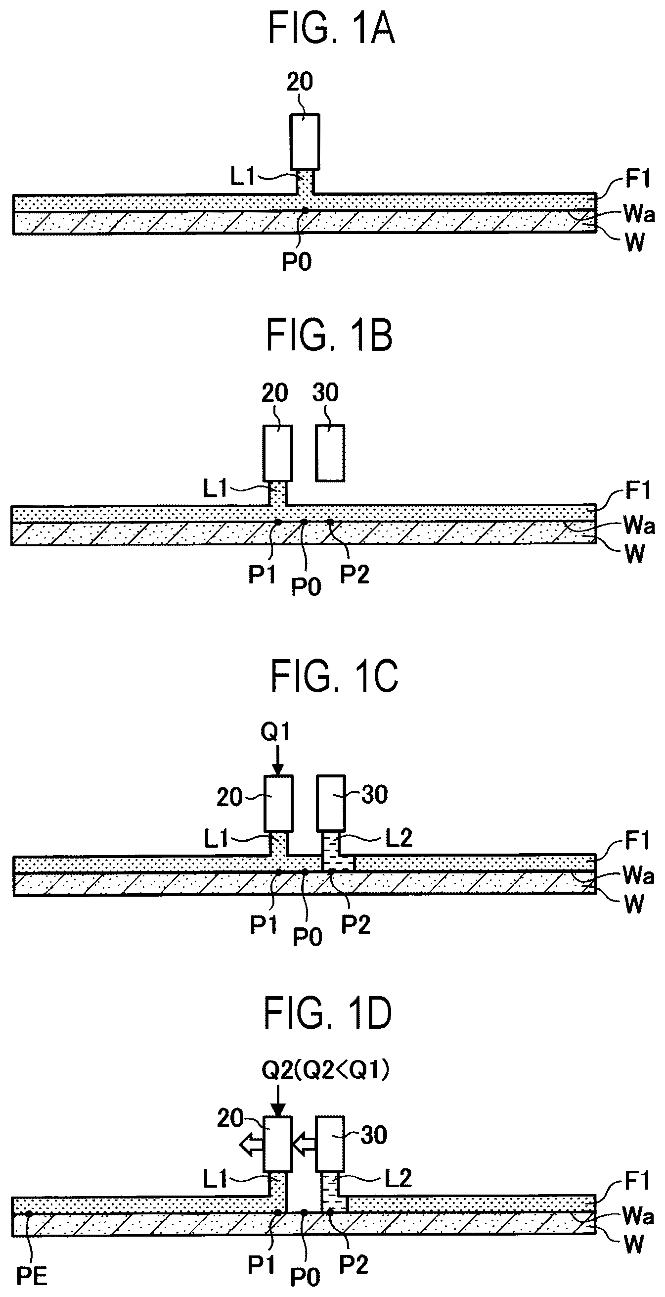
A is a view illustrating an example of S 101 in , B is a view illustrating an example of S 103 in , C is a view illustrating an example of S 104 in , and D is a view illustrating a reference example of a step following C . is a view illustrating a substrate processing apparatus according to an embodiment. is a view illustrating examples of a first movement mechanism and a second movement mechanism. is a flowchart illustrating a substrate processing method according to an embodiment. A is a view illustrating an example of step S 105 in , B is a view illustrating an example of step S 106 in , C is a view illustrating an example of step S 107 in , D is a view illustrating an example of step S 108 in , and E is a view illustrating an example of step S 109 in . is a table illustrating a substrate processing method according to an embodiment. A is a view illustrating a distribution of particles on a substrate surface processed with the substrate processing method of A to 5 E , and B is a view illustrating a distribution of particles on a substrate surface processed with the substrate processing method of A to 1 D . is a table illustrating a substrate processing method according to a first modification. is a table illustrating a substrate processing method according to a second modification. is a view illustrating an example of an inspection device of a substrate processing apparatus.
DETAILED DESCRIPTION
Hereinafter, embodiments of the present disclosure will be described with reference to the drawings. In each drawing, the same or corresponding components will be denoted by the same reference numerals, and a description thereof may be omitted. A substrate processing method includes, for example, forming a liquid film of a chemical liquid on a substrate surface, substituting the liquid film of the chemical liquid with a liquid film of a rinse liquid, substituting the liquid film of the rinse liquid with a liquid film of a drying liquid, and exposing the substrate surface from the liquid film of the drying liquid. These processes are carried out inside the same processing container. The chemical liquid is supplied to a center of the substrate surface of the rotating substrate and spreads over the entire substrate surface in a radial direction by virtue of a centrifugal force to form a liquid film. As the chemical liquid, for example, buffered hydrofluoric acid (BHF) or the like may be used. The chemical liquid is not limited to BHF, and may be, for example, dilute hydrofluoric acid (DHF) or the like. When the BHF is used, the substrate surface is rendered water-repellent in the case where the DHF is used. A plurality of types of chemical liquids may be sequentially supplied. In this case, forming a liquid film of a rinse liquid may be performed between forming a liquid film of a first chemical liquid and forming a liquid film of a second chemical liquid. The rinse liquid is supplied to the center of the substrate surface of the rotating substrate and spreads over the entire substrate surface in the radial direction by virtue of a centrifugal force, so that the chemical liquid contained in the liquid film is replaced with the rinse liquid. The rinse liquid washes away the chemical liquid remaining on the substrate surface. As the rinse liquid, pure water such as deionized water (DIW) may be used. The drying liquid is supplied to the center of the substrate surface of the rotating substrate and spreads over the entire substrate surface in the radial direction by virtue of a centrifugal force, so that the rinse liquid contained in the liquid film is substituted with the drying liquid. As the drying liquid, a liquid having a lower surface tension than that of the rinse liquid may be used. This makes it possible to suppress an uneven pattern from collapsing due to the surface tension. The drying liquid is, for example, isopropyl alcohol (IPA) or the like. After forming the liquid film of the drying liquid, the substrate surface is exposed from the liquid film of the drying liquid. The drying liquid is shaken off from the substrate surface by the rotation of the substrate. At that time, a position at which the drying liquid is supplied may be shifted from the center of the substrate surface toward a peripheral edge. By moving the supply position of the drying liquid, an opening is formed in the center of the liquid film of the drying liquid. The opening gradually expands from the center of the substrate surface toward the peripheral edge. A drying gas such as a nitrogen gas may be supplied toward an edge of the opening in order to hold the edge of the opening formed in the liquid film of the drying liquid. The supply position of the drying gas is moved following the supply position of the drying liquid. In order to replace the liquid film, the nozzle located directly above the center position of the substrate surface is replaced. For example, in order to replace the liquid film of the rinse liquid with the liquid film of the drying liquid, the nozzle located directly above the center position of the substrate surface is replaced by a drying liquid nozzle from a rinse liquid nozzle. The inventors of the present disclosure investigated a cause of generation of particles at or near the center position of the substrate surface, and found that the cause is that the liquid film is interrupted when the nozzle located directly above the center position of the substrate surface is replaced. It is considered that the residue of the liquid film adheres to the surface of the substrate due to such an interruption of the liquid film. Next, with reference to A to 1 D , a phenomenon in which the liquid film is interrupted at or near the center position of the substrate surface when the liquid film is substituted will be described. First, as illustrated in A , a first nozzle 20 supplies a rinse liquid L 1 to a center position P 0 of a substrate surface Wa, and forms a liquid film F 1 of the rinse liquid L 1 on the entire substrate surface Wa. Subsequently, as illustrated in B , the first nozzle 20 is moved outward in the radial direction of the substrate W, and the supply position of the rinse liquid L 1 is shifted from the center position P 0 to a first eccentric position P 1 . This is in preparation for supplying a drying liquid L 2 to a second eccentric position P 2 different from the first eccentric position P 1 , which prevents interference between a second nozzle 30 and the first nozzle 20 . The second eccentric position P 2 and the first eccentric position P 1 are disposed at substantially the same distance from the center position P 0 , but may be disposed at different distances. The second eccentric position P 2 and the first eccentric position P 1 are disposed near the center position P 0 so that the liquid film is not interrupted at or near the center position P 0 . Subsequently, as illustrated in C , the second nozzle 30 supplies the drying liquid L 2 to the second eccentric position P 2 in a state in which the supply position of the rinse liquid L 1 is held at the first eccentric position P 1 . A flow rate of the rinse liquid L 1 at this time is a first flow rate Q 1 . The first flow rate Q 1 is set such that the liquid film is not interrupted at or near the center position P 0 . Subsequently, as illustrated in D , the supply position of the rinse liquid L 1 starts to be shifted from the first eccentric position P 1 toward a peripheral edge position PE. The peripheral edge position PE is a position in a direction away from the center position P 0 (outward in the radial direction) from the first eccentric position P 1 . In addition, the supply position of the drying liquid L 2 starts to be shifted from the second eccentric position P 2 toward the center position P 0 . According to a reference example, as illustrated in D , when the supply position of the rinse liquid L 1 starts to be shifted outward in the radial direction from the first eccentric position P 1 , the flow rate of the rinse liquid L 1 is reduced from the first flow rate Q 1 to a second flow rate Q 2 . This is to prevent liquid splashing at the supply position of the rinse liquid L 1 . The farther the supply position of the rinse liquid L 1 is from the center position P 0 , the greater the peripheral speed and centrifugal force at the supply position, and the more likely the liquid splashes at the supply position. When the flow rate of the rinse liquid L 1 is reduced from the first flow rate Q 1 to the second flow rate Q 2 in advance, it is possible to prevent liquid from splashing at the supply position of the rinse liquid L 1 . The first flow rate Q 1 is, for example, 1,200 mL/min to 1,800 mL/min. The second flow rate Q 2 is, for example, 800 mL/min to 1,200 mL/min. The flow rate of the rinse liquid L 1 is reduced from the first flow rate Q 1 to the second flow rate Q 2 , while a flow rate of the drying liquid L 2 is maintained at a third flow rate Q 3 . The third flow rate Q 3 is, for example, 50 mL/min to 100 mL/min. As described above, when the flow rate of the rinse liquid L 1 is reduced from the first flow rate Q 1 to the second flow rate Q 2 when the supply position of the rinse liquid L 1 starts to be shifted outward in the radial direction from the first eccentric position P 1 , the liquid film may be interrupted at or near the center position P 0 , as illustrated in D . This phenomenon occurs when the substrate surface Wa is made water-repellent. This is because the rinse liquid L 1 is easily peeled off from the substrate surface Wa and is easily swept outward in the radial direction by virtue of a centrifugal force. Examples of the case in which the substrate surface Wa is made water-repellent may include a case in which the substrate surface Wa is processed with high-concentration HF, a case in which the substrate surface Wa is coated with a water-repellent resist film or the like, in addition to the case in which the substrate surface is processed with BHF. This phenomenon does not occur when the substrate surface Wa is hydrophilic. In the present embodiment, a timing T at which the flow rate of the rinse liquid L 1 is reduced from the first flow rate Q 1 to the second flow rate Q 2 is delayed in order to cope with the case in which the substrate surface Wa is made water-repellent. The timing T is after the supply position of the rinse liquid L 1 starts to be shifted outward in the radial direction from the first eccentric position P 1 . Since the timing T is delayed, it is also possible to supply the rinse liquid L 1 to the center position P 0 , and it is possible to suppress the interruption of the liquid film at or near the center position P 0 . Therefore, it is possible to suppress the adhesion of the residue of the liquid film to the substrate surface due to the interruption of the liquid film, and it is possible to suppress the generation of particles at or near the center position P 0 . Until the supply position of the drying liquid L 2 reaches the center position P 0 after the supply position of the rinse liquid L 1 starts to be shifted outward in the radial direction from the first eccentric position P 1 , the drying liquid L 2 also reaches the center position P 0 , as illustrated in B . Therefore, until the supply position of the drying liquid L 2 reaches the center position P 0 , the flow rate of the rinse liquid L 1 is reduced from the first flow rate Q 1 to the second flow rate Q 2 . That is, the timing T at which the flow rate of the rinse liquid L 1 is reduced from the first flow rate Q 1 to the second flow rate Q 2 is until the supply position of the drying liquid L 2 reaches the center position P 0 . Since the flow rate of the rinse liquid L 1 is reduced from the first flow rate Q 1 to the second flow rate Q 2 before the supply position of the rinse liquid L 1 becomes too distant from the center position P 0 , it is possible to suppress the liquid from splashing at the supply position of the rinse liquid L 1 . The timing T may be until the supply position of the drying liquid L 2 reaches the center position P 0 , may be before the supply position of the drying liquid L 2 reaches the center position P 0 , or may be when the supply position of the drying liquid L 2 reaches the center position P 0 . However, when the timing T is before the supply position of the drying liquid L 2 reaches the center position P 0 , it is possible to further suppress the liquid from splashing at the supply position of the rinse liquid L 1 . Hereinafter, the substitution of the liquid film F 1 of the rinse liquid L 1 with the liquid film F 2 of the drying liquid L 2 will be described. The rinse liquid L 1 corresponds to a processing liquid recited in the claims, and the drying liquid L 2 corresponds to a substitute liquid recited in the claims. The technique of the present disclosure is also applicable to the substitution of a liquid film of a chemical liquid with the liquid film F 1 of the rinse liquid L 1 . In this case, the chemical liquid corresponds to a processing liquid recited in the claims, and the rinse liquid L 1 corresponds to the substitute liquid recited in the claims. Next, a substrate processing apparatus 1 of the present embodiment will be described with reference to . In , an X-axis direction, a Y-axis direction, and a Z-axis direction are perpendicular to one another. The X-axis direction and the Y-axis direction are horizontal directions, and the Z-axis direction is a vertical direction. The substrate processing apparatus 1 processes the substrate surface Wa. The substrate W includes, for example, a silicon wafer, a compound semiconductor wafer, or the like. The substrate W may be a glass substrate. The substrate processing apparatus 1 includes a chuck 10 , a rotation mechanism 11 , a first nozzle 20 , a first flow rate controller 21 , a first movement mechanism 22 , a second nozzle 30 , a second flow rate controller 31 , a second movement mechanism 32 , a cup 40 , and a control device 90 . The chuck 10 holds the substrate W. The chuck 10 holds the substrate W horizontally from below such that the substrate surface Wa is oriented upward. Although the chuck 10 is a mechanical chuck in , it may be a vacuum chuck, an electrostatic chuck, or the like. The rotation mechanism 11 rotates the chuck 10 . A rotation shaft of the chuck 10 is disposed vertically. The chuck 10 holds the substrate W such that the center of the substrate surface Wa and the rotation center line of the chuck 10 coincide with each other. The first nozzle 20 supplies the rinse liquid L 1 to the substrate surface Wa of the substrate W which is rotating. The first nozzle 20 is disposed above the chuck 10 and supplies the rinse liquid L 1 to the substrate surface Wa from above. The first nozzle 20 supplies the rinse liquid L 1 vertically to the substrate surface Wa. The first flow rate controller 21 and a first opening/closing valve 23 are provided in the middle of a first supply line for supplying the rinse liquid L 1 to the first nozzle 20 . When the first opening/closing valve 23 opens a flow path of the rinse liquid L 1 , the first nozzle 20 ejects the rinse liquid L 1 . The flow rate of the rinse liquid L 1 is controlled by the first flow rate controller 21 . When the first opening/closing valve 23 closes the flow path of the rinse liquid L 1 , the first nozzle 20 stops the ejection of the rinse liquid L 1 . The first movement mechanism 22 moves the first nozzle 20 and shifts the supply position of the rinse liquid L 1 in the radial direction of the substrate surface Wa. The first movement mechanism 22 includes, for example, a swivel arm 22 a that holds the first nozzle 20 and a swivel mechanism 22 b that swivels the swivel arm 22 a . The swivel mechanism 22 b may also serve as a mechanism for raising and lowering the swivel arm 22 a . The swivel arm 22 a is disposed horizontally, holds the first nozzle 20 at one end portion of the swivel arm 22 a in a longitudinal direction, and is swiveled around a swivel axis extending downward from the other end portion of the swivel arm 22 a in the longitudinal direction (see ). In addition, the first movement mechanism 22 may include a guide rail and a linear motion mechanism instead of the swivel arm 22 a and the swivel mechanism 22 b . The guide rail is disposed horizontally, and a linear motion mechanism moves the first nozzle 20 along the guide rail. The second nozzle 30 supplies the drying liquid L 2 to the substrate surface Wa of the substrate W which is rotating. The second nozzle 30 is disposed above the chuck 10 and supplies the drying liquid L 2 to the substrate surface Wa from above. The second nozzle 30 supplies the drying liquid L 2 vertically to the substrate surface Wa. The second flow rate controller 31 and a second opening/closing valve 33 are provided in the middle of the second supply line for supplying the drying liquid L 2 to the second nozzle 30 . When the second opening/closing valve 33 opens a flow path of the drying liquid L 2 , the second nozzle 30 ejects the drying liquid L 2 . A flow rate of the drying liquid L 2 is controlled by the second flow rate controller 31 . On the other hand, when the second opening/closing valve 33 closes the flow path of the drying liquid L 2 , the second nozzle 30 stops the ejection of the drying liquid L 2 . The second movement mechanism 32 moves the second nozzle 30 and shifts the supply position of the drying liquid L 2 in the radial direction of the substrate surface Wa. The second movement mechanism 32 includes, for example, a swivel arm 32 a that holds the second nozzle 30 and a swivel mechanism 32 b that swivels the swivel arm 32 a . The swivel mechanism 32 b may also serve as a mechanism for raising and lowering the swivel arm 32 a . The swivel arm 32 a is disposed horizontally, holds the second nozzle 30 at one end portion of the swivel arm 32 a in the longitudinal direction, and is swiveled around a swivel axis extending downward from the other end portion of the swivel arm 32 a in the longitudinal direction (see ). In addition, the second movement mechanism 32 may include a guide rail and a linear motion mechanism instead of the swivel arm 32 a and the swivel mechanism 32 b . The guide rail is disposed horizontally, and a linear motion mechanism moves the second nozzle 30 along the guide rail. The cup 40 accommodates the substrate W and collects the rinse liquid L 1 and the drying liquid L 2 that are shaken off from the substrate surface Wa. The cup 40 includes a cylindrical portion 41 , a bottom cover portion 42 , and an inclined portion 43 . The cylindrical portion 41 has an inner diameter larger than a diameter of the substrate W and is disposed vertically. The bottom cover portion 42 closes an opening at a lower end of the cylindrical portion 41 . The inclined portion 43 is formed over the entire circumference of an upper end of the cylindrical portion 41 , and is inclined upward along an inward radial direction of the cylindrical portion 41 . The control device 90 controls the rotation mechanism 11 , the first flow rate controller 21 , the first movement mechanism 22 , the second flow rate controller 31 , the second movement mechanism 32 , and the like. The control device 90 is, for example, a computer, and includes a central processing unit (CPU) 91 and a storage medium 92 such as a memory, as illustrated in . The storage medium 92 stores a program for controlling various processes to be executed in the substrate processing apparatus 1 . The control device 90 controls the operation of the substrate processing apparatus 1 by causing the CPU 91 to execute the program stored in the storage medium 92 . Next, a substrate processing method of the present embodiment will be described with reference to , 5 A to 5 E, and 6 . Each step illustrated in and the like is carried out under the control of the control device 90 . First, in step S 101 of , as illustrated in A , the first nozzle 20 supplies the rinse liquid L 1 to the center position of the substrate surface Wa of the substrate W which is rotating, and forms the liquid film F 1 of the rinse liquid L 1 over the entire substrate surface Wa. Subsequently, in step S 102 , the first movement mechanism 22 starts the movement of the first nozzle 20 . The supply position of the rinse liquid L 1 starts to be shifted from the center position P 0 toward the first eccentric position P 1 . Subsequently, as illustrated in B , in step S 103 , the first movement mechanism 22 stops the movement of the first nozzle 20 and holds the supply position of the rinse liquid L 1 at the first eccentric position P 1 . Subsequently, as illustrated in C , in step S 104 , the second nozzle 30 supplies the drying liquid L 2 to the second eccentric position P 2 in the state in which the first movement mechanism 22 holds the supply position of the rinse liquid L 1 at the first eccentric position P 1 . The flow rate of the rinse liquid L 1 at this time is the first flow rate Q 1 . Subsequently, as illustrated in A , in step S 105 , the first movement mechanism 22 starts the movement of the first nozzle 20 . The supply position of the rinse liquid L 1 starts to be shifted outward in the radial direction from the first eccentric position P 1 . In addition, the second movement mechanism 32 starts the movement of the second nozzle 30 . The supply position of the drying liquid L 2 starts to be shifted from the second eccentric position P 2 toward the center position P 0 . Subsequently, in step S 106 , as illustrated in B , the first flow rate controller 21 reduces the flow rate of the rinse liquid L 1 from the first flow rate Q 1 to the second flow rate Q 2 . Since the timing T is after the supply position of the rinse liquid L 1 starts to be shifted outward in the radial direction from the first eccentric position P 1 , it is also possible to supply the rinse liquid L 1 or the drying liquid L 2 to the center position P 0 , so that it is possible to suppress the interruption of the liquid film at or near the center position P 0 . Subsequently, as illustrated in C , in step S 107 , when the supply position of the drying liquid L 2 reaches the center position P 0 , the second movement mechanism 32 stops the movement of the second nozzle 30 . The second nozzle 30 supplies the drying liquid L 2 to the center position P 0 . The drying liquid L 2 starts to spread from the center position P 0 toward the peripheral edge position PE. After the supply position of the drying liquid L 2 reaches the center position P 0 , the rotation mechanism 11 may reduce a rotation speed of the substrate W from a first rotation speed R 1 to a second rotation speed R 2 , as illustrated in . This is in preparation for coating the entire substrate surface Wa with the liquid film F 2 of the drying liquid L 2 . The drying liquid L 2 has higher volatility than that of the rinse liquid L 1 . Therefore, by reducing the rotation speed of the substrate W, a thickness of the liquid film F 2 of the drying liquid L 2 is increased, the volatilization of the drying liquid L 2 is suppressed, and the exposure of the substrate surface Wa is suppressed. The more radially outward the substrate surface Wa, the greater the centrifugal force acting on the liquid film F 2 , and the thinner the thickness of the liquid film F 2 . Therefore, before the drying liquid L 2 spreads to the peripheral edge position PE, the rotation mechanism 11 reduces the rotation speed of the substrate W from the first rotation speed R 1 to the second rotation speed R 2 . The first rotation speed R 1 is, for example, 1,000 rpm to 1,400 rpm. The second rotation speed R 2 is, for example, 500 rpm to 900 rpm. According to the present embodiment, the supply position of the rinse liquid L 1 is shifted toward the peripheral edge position PE while the supply position of the drying liquid L 2 is fixed at the center position P 0 . When the drying liquid L 2 spreads from the center position P 0 to the peripheral edge position PE, it is possible to replenish the rinse liquid L 1 in front of the drying liquid L 2 , so that it is possible to suppress the interruption of the liquid film. Therefore, it is possible to suppress the generation of particles at the peripheral edge position PE or the like. Subsequently, as illustrated in D , in step S 108 , when the supply position of the rinse liquid L 1 reaches the peripheral edge position PE, the first movement mechanism 22 stops the movement of the first nozzle 20 . The first nozzle 20 supplies the rinse liquid L 1 to the peripheral edge position PE. Lastly, as illustrated in E , in step S 109 , the first nozzle 20 stops the supply of the rinse liquid L 1 . As a result, the substitution of the liquid film F 1 of the rinse liquid L 1 with the liquid film F 2 of the drying liquid L 2 is completed. A illustrates a distribution of particles on the substrate surface Wa processed with the substrate processing method of A to 5 E . B illustrates a distribution of particles on the substrate surface Wa processed with the substrate processing method of A to 1 D . In A and 7 B , the black circles are particles. Experimental conditions in A and 7 B are as follows. The substrates W were silicon wafers, and the diameter of the substrate surfaces Wa was 300 mm. The substrate surfaces Wa were previously processed with BHF to make the substrate surfaces hydrophobic. The first rotation speed R 1 was 1,200 rpm, the second rotation speed R 2 was 700 rpm, the first flow rate Q 1 was 1,500 mL/min, the second flow rate Q 2 was 1,000 mL/min, and the third flow rate Q 3 was 75 mL/min. As is clear from a comparison of A and 7 B , it can be seen that, when the timing T at which the flow rate of the rinse liquid L 1 is reduced from the first flow rate Q 1 to the second flow rate Q 2 is delayed, it is possible to suppress the generation of particles at or near the center position P 0 . Next, a substrate processing method according to a first modification will be described with reference to . Hereinafter, differences between the present modification ( ) and the above-described embodiment ( ) will be mainly described. In the present modification, as illustrated in , when the supply position of the rinse liquid L 1 starts to be shifted outward in the radial direction from the first eccentric position P 1 (S 105 of , A ), the second flow rate controller 31 increases the flow rate of the drying liquid L 2 from the third flow rate Q 3 to a fourth flow rate Q 4 . The fourth flow rate Q 4 is, for example, 120 mL/min to 180 mL/min. When the supply position of the rinse liquid L 1 starts to be shifted outward in the radial direction from the first eccentric position P 1 , the flow rate of the drying liquid L 2 increases, so that the drying liquid L 2 also reaches the center position P 0 . Therefore, it is possible to suppress the interruption of the liquid film at or near the center position P 0 . Until the supply position of the drying liquid L 2 reaches the center position P 0 , the second flow rate controller 31 reduces the flow rate of the drying liquid L 2 from the fourth flow rate Q 4 to a fifth flow rate Q 5 . The fifth flow rate Q 5 is, for example, 50 mL/min to 100 mL/min. The fifth flow rate Q 5 may be smaller than the fourth flow rate Q 4 and may be equal to the third flow rate Q 3 . In the present modification, when the supply position of the drying liquid L 2 reaches the center position P 0 , the second flow rate controller 31 reduces the flow rate of the drying liquid L 2 from the fourth flow rate Q 4 to the fifth flow rate Q 5 . When the supply position of the drying liquid L 2 reaches the center position P 0 , the drying liquid L 2 surely reaches the center position P 0 . In the present modification, as in the above-described embodiment, the timing T at which the flow rate of the rinse liquid L 1 is reduced from the first flow rate Q 1 to the second flow rate Q 2 is after the movement of the supply position of the rinse liquid L 1 outward in the radial direction from the first eccentric position P 1 is started, but may be when the movement is started (see A to 1 D ). At that time, when the flow rate of the drying liquid L 2 increases from the third flow rate Q 3 to the fourth flow rate Q 4 , it is possible to suppress the interruption of the liquid film at or near the center position P 0 . Next, with reference to , a substrate processing method according to a second modification will be described. Hereinafter, differences between the present modification ( ) and the above-described embodiment ( ) will be mainly described. In the present modification, as illustrated in , when the supply position of the rinse liquid L 1 starts to be shifted outward in the radial direction from the first eccentric position P 1 , the rotation mechanism 11 reduces the rotation speed of the substrate W from the first rotation speed R 1 to a third rotation speed R 3 . The third rotation speed R 3 is, for example, 800 rpm to 1,200 rpm. The third rotation speed R 3 may be smaller than the first rotation speed R 1 . When the supply position of the rinse liquid L 1 starts to be shifted outward in the radial direction from the first eccentric position P 1 , the rotation speed of the substrate W is reduced, so that the centrifugal force is reduced, and the rinse liquid L 1 or the drying liquid L 2 will also reach the center position P 0 . Therefore, it is possible to suppress the interruption of the liquid film at or near the center position P 0 . Until the supply position of the drying liquid L 2 reaches the center position P 0 , the rotation mechanism 11 further reduces the rotation speed of the substrate W from the third rotation speed R 3 to the second rotation speed R 2 . The third rotation speed R 3 is smaller than the first rotation speed R 1 and larger than the second rotation speed R 2 . The second rotation speed R 2 is, for example, 500 rpm to 900 rpm. In the present modification, when the supply position of the drying liquid L 2 reaches the center position P 0 , the rotation mechanism 11 reduces the rotation speed of the substrate W from the third rotation speed R 3 to the second rotation speed R 2 . When the supply position of the drying liquid L 2 reaches the center position P 0 , the drying liquid L 2 surely reaches the center position P 0 . Although the third rotation speed R 3 in the present modification is larger than the second rotation speed R 2 , the third rotation speed R 3 may be equal to the second rotation speed R 2 . This may reduce the effort of changing the rotation speed. Further, in the present modification, as in the above-described embodiment, the timing T at which the flow rate of the rinse liquid L 1 is reduced from the first flow rate Q 1 to the second flow rate Q 2 is after the movement of the supply position of the rinse liquid L 1 outward in the radial direction from the first eccentric position P 1 is started, but may be when the movement is started (see A to 1 D ). At that time, when the rotation speed of the substrate W is reduced from the first rotation speed R 1 to the third rotation speed R 3 , it is possible to suppress the interruption of the liquid film at or near the center position P 0 . Suppressing the interruption of the liquid film at or near the center position P 0 may be implemented by at least one of the following procedures (1) to (3). A combination thereof is not particularly limited, and all of the following procedures (1) to (3) may be combined with one another. (1) After the supply position of the rinse liquid L 1 starts to be shifted outward in the radial direction from the first eccentric position P 1 , the flow rate of the rinse liquid L 1 is reduced from the first flow rate Q 1 to the second flow rate Q 2 . (2) When the supply position of the rinse liquid L 1 starts to be shifted outward in the radial direction from the first eccentric position P 1 , the flow rate of the drying liquid L 2 is increased from the third flow rate Q 3 to the fourth flow rate Q 4 . (3) When the supply position of the rinse liquid L 1 starts to be shifted outward in the radial direction from the first eccentric position P 1 , the rotation speed of the substrate W is reduced from the first rotation speed R 1 to the third rotation speed R 3 . Next, an inspection device 50 of the substrate processing apparatus 1 will be described with reference to . The inspection device 50 inspects wettability of the rinse liquid L 1 with respect to the substrate surface Wa. For example, the inspection device 50 captures an image of the substrate surface Wa of the rotating substrate W with a camera 51 or the like in a state in which the liquid film F 1 of the rinse liquid L 1 is formed on the substrate surface Wa, processes the captured image, and determines the wettability depending on whether the entire substrate surface Wa is coated with the liquid film F 1 . The camera 51 may be installed inside a processing container that accommodates the chuck 10 or the like, or may be installed outside the processing container. As illustrated in , when the entire substrate surface Wa is not coated with the liquid film F 1 and the peripheral edge of the substrate surface Wa is exposed from the liquid film F 1 , the inspection device 50 determines that the rinse liquid L 1 has poor wettability with respect to the substrate surface Wa and is made water-repellent. When the substrate surface Wa is made water-repellent, the rinse liquid L 1 is easily peeled off, and the peripheral edge of the substrate surface Wa is exposed. This is because the centrifugal force is larger at the peripheral edge of the substrate surface Wa than at the center. Meanwhile, when the entire substrate surface Wa is coated with the liquid film F 1 , the inspection device 50 determines that the rinse liquid L 1 has good wettability with respect to the substrate surface Wa and is hydrophilic. The control device 90 determines the timing T at which the flow rate of the rinse liquid L 1 is reduced from the first flow rate Q 1 to the second flow rate Q 2 based on the inspection result of the inspection device 50 . Specifically, as illustrated in , when the entire substrate surface Wa is not coated with the liquid film F 1 and the peripheral edge of the substrate surface Wa is exposed from the liquid film F 1 , the timing T is set to a time after the supply position of the rinse liquid L 1 starts to be shifted outward in the radial direction from the first eccentric position P 1 and until the supply position of the drying liquid L 2 reaches the center position P 0 . On the other hand, when the entire substrate surface Wa is coated with the liquid film F 1 , the timing T is set to a time when the supply position of the rinse liquid L 1 starts to be shifted outward in the radial direction from the first eccentric position P 1 . Although the embodiments or the like of the substrate processing method and the substrate processing apparatus according to the present disclosure have been described above, the present disclosure is not limited to the above-described embodiments or the like. Various changes, modifications, substitutions, additions, deletions, and combinations can be made within the scope of the claims. Of course, these also fall within the technical scope of the present disclosure. This application claims priority based on Japanese Patent Application No. 2020-037866 filed with the Japan Patent Office on Mar. 5, 2020, and the disclosure of Japanese Patent Application No. 2020-037866 is incorporated herein in its entirety by reference. EXPLANATION OF REFERENCE NUMERALS L 1 : rinse liquid (processing liquid), L 2 : drying liquid (substitute liquid); Wa: substrate surface, P 0 : center position, P 1 : first eccentric position, P 2 : second eccentric position
Figures (10)
Citations
This patent cites (36)
- US6334902
- US6770151
- US7806989
- US7901514
- US8769842
- US9028621
- US11676835
- US12027394
- US2003/0192577
- US2004/0045589
- US2005/0208774
- US2007/0017555
- US2007/0223342
- US2015/0243542
- US2015/0270146
- US2017/0047219
- US2017/0256392
- US2017/0292192
- US2017/0301534
- US2018/0076018
- US2018/0195178
- US2019/0067047
- US2019/0196335
- US2019/0237322
- US2019/0294049
- US2020/0234998
- US2020/0365425
- US2021/0166957
- US2021/0197224
- US2022/0399208
- US2023/0099012
- US2023/0268207
- US2015-213105
- US2016-082227
- US2019073905
- US2021177078